Interface 7-Segment Display with Raspberry Pi 4


Thank you for being here for today's tutorial of our in-depth Raspberry Pi programming tutorial. The previous tutorial taught us how to install a PIR sensor on a Raspberry Pi 4 to create a motion detector. However, this tutorial will teach you how to connect a single seven-segment display to a Raspberry Pi 4. In the following sections, we will show you how to connect a Raspberry Pi to a 4-digit Seven-Segment Display Module so that the time can be shown on it.

Seven-segment displays are a simple type of Display that use eight light-emitting diodes to show off decimal numbers. It's common to find it in gadgets like digital clocks, calculators, and electronic meters that show numbers. Raspberry Pi, built around an ARM chip, is widely acknowledged as an excellent Development Platform. Its strong processing power can do amazing things in the hands of electronics enthusiasts and students. If we can figure out how to have it talk to the outside world and process data via an output, then we'll have a real chance of accomplishing all this. We analyze the data by viewing it on an LCD screen or other Display. Numerous sensors can detect specific parameters in the physical world and convert them to the digital world. It would never make sense to utilize a PI LCD panel to display a minimal quantity of information. Here, a 7-Segment or 16x2-Alphanumeric LCD panel is the preferred method of presentation.
There are few uses for a 7-segment display that don't need an LCD panel, even though a 16x2 LCD is preferable in most. If all you need to do is show some numbers, then an LCD, which has the downside of having a small character size, is excessive. Compared to a regular LCD screen, seven segments have the upper hand in dim environments and can be seen from wider angles. Let's get started.
Components
Jumper wires
Seven segment display
1KΩresistors
Breadboard
The 7-Segment and 4-Digit Display Modules
The seven segments of a 7 Segment Display are each lit up by an individual LED to show the digits. To show the number 5, for example, you would make the glow pins for segments a, f, g, c, and d on the 7-segment high. This particular 7-segment display is a Common Cathode version, although there is also a Common Anode version.

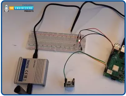
One 7-Segment Display Interfacing with Pi 4

The wiring diagram for connecting a 7-segment display to a Raspberry Pi is shown below. Here, 7-Segment Common Cathode has been utilized.

So, we'll simulate an 8-bit PORT on PI using its eight GPIO pins. Here, GPIO12 is the Most Significant Bit (MSB), while GPIO13 is the Least Significant Bit (LSB) (Most Significant Bit).
If we wish to show the number 1, we must activate both segments B and C. We must supply voltage to GPIO6 and GPIO16 to power segments B and C. Accordingly, the hexadecimal value of "PORT" is "06," and the byte value of "PORT" is "0b00000110." If we raise both pins to their highest positions, the number "1" will be shown.

The value for every displayable digit has been recorded and saved in a Character String with the label 'DISPLAY .'We have then used the Function 'PORT' to call those values one at a time and display the relevant digit.
Explanation of the Code
Once everything is wired up according to the schematic, we can power up the PI and begin using PYTHON to write the program. Below is a function that allows us to program the GPIO pins on the PI, and we'll go over the few commands we'll be using in the PYTHON program to do so. We are also changing the name of the GPIO pins in the hardware from "GPIO" to "IO," which will be used throughout the code.

import RPi.GPIO as IO
The general-purpose input/output (GPIO) pins we need to use may be occupied with other tasks. If that's the case, the program's execution will be interrupted by warnings. The below command instructs the PI to continue running the software regardless of the warnings.

IO.setwarnings(False)
Pin numbers on the board and pin functions can be used to refer to PI's GPIOs. This GPIO5 is similar to the one labeled "PIN 29" on the board. Here we specify whether the number 29 or the number 5 will stand in for the pin.

IO.setmode (IO.BCM)
To use the LCD's data and control pins, we have assigned those functions to eight of the GPIO pins.

IO.setup(13,IO.OUT)
IO.setup(6,IO.OUT)
IO.setup(16,IO.OUT)
IO.setup(20,IO.OUT)
IO.setup(21,IO.OUT)
IO.setup(19,IO.OUT)
IO.setup(26,IO.OUT)
IO.setup(12,IO.OUT)
If the condition between the brackets evaluates to true, the looped statements will be run once. The value of PIN13 would be HIGH if and only if bit0 of the 8-bit 'pin' is true. There are eight 'if else' conditions, one for each of bits 0 through 7, so that each LED in the seven-segment Display can be set to either the High or Low state, depending on the value of the corresponding bit.

if(pin&0x01 == 0x01):
IO.output(13,1)
else:
IO.output(13,0)
As x increases from 0 to 9, the loop will be run 10 times for each command.

for x in range(10):
The following command can create an infinite loop, with which the statements included within the loop will be run repeatedly.

While 1:
All other commands and functions have been commented on in the following code.
Single 7-segment Display complete code
import RPi.GPIO as IO # calling for the header file, which helps us use GPIO's of PI
import time # calling for time to provide delays in the program
DISPLAY = [0x3F,0x06,0x5B,0x4F,0x66,0x6D,0x7D,0x07,0x7F,0x67] # string of characters storing PORT values for each digit.
IO.setwarnings(False) # do not show any warnings.
IO.setmode (IO.BCM) # programming the GPIO by BCM pin numbers. (like PIN29 as‘GPIO5’)
IO.setup(13,IO.OUT) # initialize GPIO Pins as outputs
IO.setup(6,IO.OUT)
IO.setup(16,IO.OUT)
IO.setup(20,IO.OUT)
IO.setup(21,IO.OUT)
IO.setup(19,IO.OUT)
IO.setup(26,IO.OUT)
IO.setup(12,IO.OUT)
def PORT(pin): # assigning GPIO logic by taking the 'pin' value
if(pin&0x01 == 0x01):
IO.output(13,1) # if bit0 of 8bit 'pin' is true, pull PIN13 high
else:
IO.output(13,0) # if bit0 of 8bit 'pin' is false, pull PIN13 low
if(pin&0x02 == 0x02):
IO.output(6,1) # if bit1 of 8bit 'pin' is true, pull PIN6 high
else:
IO.output(6,0) #if bit1 of 8bit 'pin' is false, pull PIN6 low
if(pin&0x04 == 0x04):
IO.output(16,1)
else:
IO.output(16,0)
if(pin&0x08 == 0x08):
IO.output(20,1)
else:
IO.output(20,0)
if(pin&0x10 == 0x10):
IO.output(21,1)
else:
IO.output(21,0)
if(pin&0x20 == 0x20):
IO.output(19,1)
else:
IO.output(19,0)
if(pin&0x40 == 0x40):
IO.output(26,1)
else:
IO.output(26,0)
if(pin&0x80 == 0x80):
IO.output(12,1) # if bit7 of 8bit 'pin' is true, pull PIN12 high
else:
IO.output(12,0) # if bit7 of 8bit 'pin' is false, pull PIN12 low
While 1:
for x in range(10): # execute the loop ten times incrementing x value from zero to nine
pin = DISPLAY[x] # assigning value to 'pin' for each digit
PORT(pin); # showing each digit on display
time.sleep(1)
Output

The process of displaying a single number character on a 7-segment display is complete. However, we'd need more than a single 7-segment display to express information with more than one digit. Therefore, we will use a 4-digit seven-segment display circuit for this session.

Four individual Seven-Segment Displays have been linked up here. For a 4-digit 7-segment display, we know that each module will have 10 pins, so there will be 40 pins total. Soldering that many pins onto a dot board would be a hassle for anyone; thus, I recommend that anyone using a 7-segment display do so by purchasing a module or creating their PCB. See below for a diagram of the relevant connections:

In the preceding diagrams, we can see that the A-lines of all four displays are linked together as one A, and the same is true for B, C.... up until DP, which is essential for understanding how the 4-digit seven-segment module functions. Put another way, if trigger A is activated, the state of all 4 A's should be high.
Nonetheless, this never occurs. The four extra pins labeled D0 through D3 (D0, D1, D2, and D3) let us select which of the four displays is driven high. As an illustration, if I want my output to appear solely on the second Display, I would set D1 to high and leave D0, D2, and D3 at low. Using pins D0–D3 and A–DP, we can easily choose which displays should be on and which characters should be shown.
Using a Pi 4 to interface with a 4-digit, 7-segment display module
Let's check the many options for interfacing this 4-digit seven-segment Display with the Raspberry Pi. As can be seen in the diagram below, there are 16 pins on the 7-segment module. Even if your module's resources are limited, it will provide at least the following.
Segmented pins, either 7 or 8 segments (pins 1 to 8)
Pin holder to the ground (here pin 11)
A 4-digit code to unlock the door (pins 13 to 16)
See below for the wiring diagram of a digital clock built with a Raspberry Pi and a 4-digit Seven-segment display module:

You can also use the following table to ensure your connections are correct and follow the diagrams.


Locating the module's pins is the first step in making electrical connections. Identifying the Raspberry Pi's GPIO pins can be tricky; I've included an image to help.

Raspberry Pi programming
Here, RPi is programmed in the Python programming language. The Raspberry Pi can be programmed in a wide variety of ways. Since Python 3 has become the de facto standard, we've opted to use that version as our integrated development environment (IDE). At the bottom of this guide, you'll find the whole Python code.
We'll go over the PYTHON instructions we'll be using for this project: first, we'll import the library's GPIO file; next, using the below function, we'll be able to program the Pi 4's GPIO pins. We are also changing the name of the GPIO pins in the hardware from "GPIO" to "IO," which will be used throughout the code. We've brought in time and DateTime to get the current time from Rasp Pi.

import RPi.GPIO as GPIO
import time, DateTime
The GPIO pins we're trying to use are already being used for something else. The program's execution will be interrupted with warnings if this is the case. The PI will be instructed to disregard the errors and continue with the software using the below command.

IO.setwarnings(False)
The physical pin number and the corresponding function number can refer to PI's GPIOs. As with 'PIN 29,' GPIO5 is a physical component on the circuit board. In this case, we specify whether the number "29" or "5" will stand in for the pin. GPIO. In BCM notation, GPIO5 pin 29 will be represented by a 5.

IO.setmode (GPIO.BCM)
As is customary, we'll start by setting the pins to their default values; in this case, both the segment and digit pins will be used as outputs. In our code, we organize the segment pins into arrays and set their values to zero by declaring them to be GPIO.OUT.

segment8 = (26,19,13,6,5,11,9,10)
for segment in segment8:
GPIO.setup(segment, GPIO.OUT)
GPIO.output(segment, 0)
We do the same thing with the digital pins, but we set them to output and set them to zero by default.

#Digit 1
GPIO.setup(7, GPIO.OUT)
GPIO.output(7, 0) #Off initially
#Digit 2
GPIO.setup(8, GPIO.OUT)
GPIO.output(8, 0) #Off initially
#Digit 3
GPIO.setup(25, GPIO.OUT)
GPIO.output(25, 0) #Off initially
#Digit 4
GPIO.setup(24, GPIO.OUT)
GPIO.output(24, 0) #Off initially
Numbers on a seven-segment display must be formed into arrays. To show a single digit, we need to toggle the on/off status of all but the dot pin of the 7-segment Display. For the numeral 5, for instance, we can use this setup:

For all alphabets and numerals, there is an equivalent sequence number. You can write on your own or utilize the handy table provided.

Using this information, we can create arrays for each digit in our Python code, as demonstrated below.

null = [0,0,0,0,0,0,0]
zero = [1,1,1,1,1,1,0]
one = [0,1,1,0,0,0,0]
two = [1,1,0,1,1,0,1]
three = [1,1,1,1,0,0,1]
four = [0,1,1,0,0,1,1]
five = [1,0,1,1,0,1,1]
six = [1,0,1,1,1,1,1]
seven = [1,1,1,0,0,0,0]
eight = [1,1,1,1,1,1,1]
nine = [1,1,1,1,0,1,1]
Let's bypass the function in the code that would otherwise be executed before entering the while loop and begin displaying characters on our 7-segment Display. If you hook up a Raspberry Pi to the internet, it will read the current time and divide it into four separate variables. For instance, when the time is 10.45, the values assigned to h1 and h2 will be 1 and 0, while m1 and m2 will be 4 and 5, respectively.

now = DateTime.DateTime.now()
hour = now.hour
minute = now.minute
h1 = hour/10
h2 = hour % 10
m1 = minute /10
m2 = minute % 10
print (h1,h2,m1,m2)
These four numbers will be displayed on one of our four digits. The lines below can be used to convert a variable's value to a decimal. Here, we show the value in variables on the 7-segment Display by using the function print segment (variable) with the digit 1 set to the highest possible value. You may be asking why we turn off this digit and why there's a delay after that.

GPIO.output(7, 1) #Turn on Digit One
print_segment (h1) #Print h1 on segment
time.sleep(delay_time)
GPIO.output(7, 0) #Turn off Digit One
This is because the user will only be able to see the full four-digit number if all four digits are shown at once, and we all know that this isn't possible.
How, then, can we simultaneously show all four digits? With luck, our MPU is considerably quicker than the human eye. Therefore we offer one number at a time but exceptionally quickly. The MPU and segment display are given 2ms (variable delay time) to process each digit before we go on to the next. A human being cannot detect this 2ms lag; therefore, it appears as though all four digits illuminate simultaneously.
Understanding how to use print segment(variable) is the final puzzle piece. Arrays that have been declared outside of this function are used within it. As a result, the value of any variable passed to this function must be inside the range (0-9) so that the character variable can use in a meaningful comparison. Here, we check the variable against the value 1. The same is true for all comparisons with numbers between zero and nine. Assigning each value from the arrays to the appropriate segment pins is what we do if a match is found.

def print_segment(character):
if character == 1:
for i in range(7):
GPIO.output(segment8[i], one[i])
Show the time on a 4-digit 7-segment display.
Use the provided schematic and code to connect your components and set up your Raspberry Pi. Once you've finished setting everything up, you can open the software and check the 7-segment Display to see the time. However, before doing this, you should check a few things.
If you want to be sure your Raspberry Pi isn't stuck in the past, you should update its time.
If you want to utilize a 7-segment display on your Raspberry Pi, you'll need to plug it into an adapter rather than a computer's USB connection because of the large amount of current it consumes.
Complete code
import RPi.GPIO as GPIO
import time, DateTime
now = datetime.datetime.now()
GPIO.setmode(GPIO.BCM)
GPIO.setwarnings(False)
#GPIO ports for the 7seg pins
segment8 = (26,19,13,6,5,11,9,10)
for segment in segment8:
GPIO.setup(segment, GPIO.OUT)
GPIO.output(segment, 0)
#Digit 1
GPIO.setup(7, GPIO.OUT)
GPIO.output(7, 0) #Off initially
#Digit 2
GPIO.setup(8, GPIO.OUT)
GPIO.output(8, 0) #Off initially
#Digit 3
GPIO.setup(25, GPIO.OUT)
GPIO.output(25, 0) #Off initially
#Digit 4
GPIO.setup(24, GPIO.OUT)
GPIO.output(24, 0) #Off initially
null = [0,0,0,0,0,0,0]
zero = [1,1,1,1,1,1,0]
one = [0,1,1,0,0,0,0]
two = [1,1,0,1,1,0,1]
three = [1,1,1,1,0,0,1]
four = [0,1,1,0,0,1,1]
five = [1,0,1,1,0,1,1]
six = [1,0,1,1,1,1,1]
seven = [1,1,1,0,0,0,0]
eight = [1,1,1,1,1,1,1]
nine = [1,1,1,1,0,1,1]
def print_segment(charector):
if charector == 1:
for i in range(7):
GPIO.output(segment8[i], one[i])
if charector == 2:
for i in range(7):
GPIO.output(segment8[i], two[i])
if charector == 3:
for i in range(7):
GPIO.output(segment8[i], three[i])
if charector == 4:
for i in range(7):
GPIO.output(segment8[i], four[i])
if charector == 5:
for i in range(7):
GPIO.output(segment8[i], five[i])
if charector == 6:
for i in range(7):
GPIO.output(segment8[i], six[i])
if charector == 7:
for i in range(7):
GPIO.output(segment8[i], seven[i])
if charector == 8:
for i in range(7):
GPIO.output(segment8[i], eight[i])
if charector == 9:
for i in range(7):
GPIO.output(segment8[i], nine[i])
if charector == 0:
for i in range(7):
GPIO.output(segment8[i], zero[i])
return;
while 1:
now = DateTime.DateTime.now()
hour = now.hour
minute = now.minute
h1 = hour/10
h2 = hour % 10
m1 = minute /10
m2 = minute % 10
print (h1,h2,m1,m2)
delay_time = 0.001 #delay to create the virtual effect
GPIO.output(7, 1) #Turn on Digit One
print_segment (h1) #Print h1 on segment
time.sleep(delay_time)
GPIO.output(7, 0) #Turn off Digit One
GPIO.output(8, 1) #Turn on Digit One
print_segment (h2) #Print h1 on segment
GPIO.output(10, 1) #Display point On
time.sleep(delay_time)
GPIO.output(10, 0) #Display point Off
GPIO.output(8, 0) #Turn off Digit One
GPIO.output(25, 1) #Turn on Digit One
print_segment (m1) #Print h1 on segment
time.sleep(delay_time)
GPIO.output(25, 0) #Turn off Digit One
GPIO.output(24, 1) #Turn on Digit One
print_segment (m2) #Print h1 on segment
time.sleep(delay_time)
GPIO.output(24, 0) #Turn off Digit One
#time.sleep(1)
Output
A similar section should appear below if everything is functioning as it should.

7-segment Display limitations
Typically, only 16 hexadecimal digits can be shown on a seven-segment display. Some show the digits 0-9, whereas others can show more. Seven-segment displays can only show a maximum of 16 values due to a lack of input leads. However, LED technology does allow for more than this. Even with the help of integrated circuit technology, the possible permutations of the seven parts on the screen are very few.
Conclusion
This guide taught us how to connect a 7-segment screen to a Raspberry Pi 4. The seven-segment Display, which we learned is employed in digital timers, clocks, and other electrical gadgets, are a cheap, basic electrical circuit and reliable module. Seven-segment displays can either be "common-anode" (where the common point is the power input) or "common-cathode" (where the common end is grounded). After that, we coded some python scripts to show numbers on a single seven-segment model and the time across four such screens. Next, we'll see how to use a Raspberry Pi 4 as the basis for a low-power Bitcoin miner.