


Touch Sensor Library for Proteus V2.0 (TTP223 + Arduino)


Hello friends, I hope you all are doing great. Today, I am going to share the new Touch Sensor Library for Proteus V2.0. It simulates the popular TTP223 capacitive touch module: the small red board with a round touch pad that works like a push button without any moving parts. With this Touch Sensor Library for Proteus, you touch the pad with the mouse or with buttons, and your Arduino reads the I/O pin exactly as it reads a real module: LOW while the pad is free and HIGH while a finger is on it.
Version 2.0 is the next version of our touch sensor library, built around the behaviour of the real chip: the calibration after power-on, the slower first touch while the chip sleeps, the four jumper modes, the max on time and cover sheets in front of the pad. You get two devices: TTP223 Simple, with a touch scene on the schematic, and TTP223 Advance, with a pop-up window and four measured touch sensor test tools. The new TTP223 Arduino Proteus demo is a touch lamp on two Arduino UNOs, shown in the compact Simple interface of our TEP Serial Monitor. Have you used an earlier version? Then jump to "What's New" below.
NOTICE: This library is very special to our team. Our TTP223 model has the chip's calibration, its low-power and fast response times, the four jumper modes, the max on time with its re-calibration, cover sheets, and an event log that measures every touch. It took our team a lot of hard work, many test runs and many design changes. Your feedback is the fuel that keeps us going, so please tell us what you think in the comments below or in the Touch Sensor Library board of our forum. And if our free libraries help you, you can buy us a coffee. So, let's get started with the Touch Sensor Library for Proteus:
What is the TTP223 Touch Sensor?
The TTP223, made by Tontek, is a single-key capacitive touch chip. A finger near its pad adds a tiny capacitance, and the chip measures that change. When the change is big enough, the chip switches its output pin. The TTP223 is best known on a small red module with a round touch pad. That module carries the TTP223-BA6, a six-pin chip marked "223B", together with one LED and two solder jumpers, A and B. On the real module, the chip, the LED and the jumpers sit on the back, and the pad side is plain.
A touch pad has no moving parts and no mechanical contact, and it even works through a thin plastic or glass panel. That makes the TTP223 a favourite for touch lamps, hidden switches behind a front panel and simple user interfaces. The module has three pins: I/O (the output), VCC and GND. The chip drives I/O HIGH and LOW itself, so your Arduino needs no pull-up resistor and no library to read it.
The TTP223 at a Glance
| Feature | Value |
|---|---|
| Chip | TTP223-BA6 from Tontek, marked "223B" on the module |
| Supply | 2.0 to 5.5 V |
| Output | I/O, the chip's CMOS output: it drives 0 V and VCC itself |
| Pins | I/O, VCC, GND (VCC is in the middle on every module) |
| Response | At most about 60 ms in fast mode and 220 ms in low-power mode (datasheet, at 3 V) |
| Release | About 60 ms after the finger is lifted |
| Calibration | About 0.5 s after power-on |
| Modes | Four, set with solder jumper A (AHLB) and jumper B (TOG) |
| Max on time | None in the BA6 datasheet; users report 7 to 12 s |
| Covers | Works through a few mm of plastic or glass; no metal in front of the pad |
| LED | One, lit while I/O is HIGH |
Touch Sensor Terms You Will See in This Article
| Term | Meaning |
|---|---|
| Capacitive touch | Sensing a finger by the small capacitance it adds to the pad |
| Baseline | The pad's "nothing touched" value, learned during the calibration |
| Threshold | How far above the baseline the signal must rise to count as a touch |
| Signal | In our model: the finger's effect as a multiple of the threshold (3.0 x on the bare pad) |
| Calibration | The chip measures its baseline; touches are ignored meanwhile |
| Low-power mode | The chip sleeps and checks the pad only now and then, so a touch takes up to 220 ms |
| Fast mode | After a touch, the chip stays awake for 12 s and answers in 60 ms |
| Response / release | The delay from the finger's contact to OUT, and from the lift to OUT |
| AHLB | The chip's active-high / active-low option, set by jumper A |
| TOG | The chip's toggle option, set by jumper B |
| Momentary / toggle | OUT follows the finger / OUT flips on each touch |
| Max on time | After a very long touch, the chip re-calibrates and OUT goes back to idle |
| OUT | The module's I/O pin, as the panels call it |
How the TTP223 Decides a Touch
Calibration After Power-On
For about 0.5 s after power-on, the chip measures the pad and stores that value as its baseline, and it ignores touches. A finger on the pad at that time becomes the "nothing touched" reference: the chip ignores it until it is lifted, and then re-calibrates for 1 s. So never touch the pad in the first half second; the demo sketch waits 0.6 s for the same reason.
Response Time: Sleeping and Awake
The TTP223-BA6 on these modules sleeps in its low-power mode, so the first touch after a quiet time takes up to 220 ms to reach the output. A touch wakes the chip into fast mode for 12 s, and then it answers in 60 ms. The release always takes 60 ms. These are the datasheet's maximum values at 3 V, and our model uses them exactly. A contact shorter than the response time is not reported at all.
The Max On Time
Hold the pad for a long time and the output drops back to idle, although your finger is still there. The chip re-calibrates, and your finger becomes the new baseline. The BA6 datasheet gives no number for this, but users report 7 to 12 s; our model uses 10 s (the MAXON property). Lift the finger, give the chip a moment for its 1 s re-calibration, and touch again.
Cover Sheets in Front of the Pad
The pad senses through a thin plastic or glass panel, so you can hide it behind the front of your project. A thicker cover weakens the signal. Our model gives each cover a signal factor against the threshold: bare pad 3.0 x, plastic 2 mm 2.0 x, glass 5 mm 1.6 x and wood 10 mm 0.6 x. Below 1.0, the chip never sees the touch. These factors are our estimates, not datasheet values.
The Two Jumpers and the Four Modes
The two solder jumpers select the chip's options. Jumper A is AHLB, the output level, and jumper B is TOG, the mode. Both open is the factory setting:
| Jumper A | Jumper B | OUT idle | When touched | Mode |
|---|---|---|---|---|
| Open | Open | LOW | HIGH while touched | Momentary, active HIGH (factory setting) |
| Closed | Open | HIGH | LOW while touched | Momentary, active LOW |
| Open | Closed | LOW | Flips on each touch | Toggle, starts LOW |
| Closed | Closed | HIGH | Flips on each touch | Toggle, starts HIGH |
The module's LED follows the output: it is lit while I/O is HIGH. With jumper A closed, it therefore lights while the pad is NOT touched.
What's New in Touch Sensor Library for Proteus V2.0
Our team has shared earlier versions of a touch sensor library for Proteus. Version 2.0 is a new design around the real TTP223 behaviour:
- Two devices in
TEPTTP223.LIB: TTP223 Simple (TTP223TEP) with the touch scene on the sheet, and TTP223 Advance (TTP223ADVTEP) with a pop-up window. - A live red TTP223 board: the pad glows cyan, amber or violet, the module's LED follows OUT, and the PWR and EDGE LEDs and the animated TOUCH VIEW screen are TEP additions.
- The chip's timing: the 0.5 s calibration, 220 ms while the chip sleeps, 60 ms when it is awake and on release, short contacts not reported, and the 10 s max on time with its re-calibration.
- Four jumper modes and four cover sheets, set with buttons, a click on the mode table or the properties.
- An event log with measured values: every contact with its signal, every touch and release with its delay, and how long OUT was active.
- Four measured test tools on the Advance device: Mode table, Response time, Max on time and Cover sweep.
- A two-UNO touch lamp demo with our TEP Serial Monitor instead of the Virtual Terminal, plus serial commands for the lamp mode and the active level.
- A lighter simulation: the panels redraw only what changed, and the two-UNO demo ran at about 0.6 x real time in our Proteus test with the pop-up open.
- A small package: about 1.40 MB, without the C++ source code.
Touch Sensor Library for Proteus: Simple vs Advance
Both devices run the same model with the same properties; only the panel differs:
| Feature | Simple | Advance |
|---|---|---|
| Full TTP223 model (calibration, response times, four modes, max on time, covers) | ✔ | ✔ |
| Red TTP223 board: pad glow, PWR / LED / EDGE LEDs, jumpers A and B, TOUCH VIEW screen | ✔ | ✔ |
| Touch scene on the schematic: side view, mode table, last 10 s, buttons | ✔ | ✘ |
| Panel you close with a red X and open again with the board button | ✔ | ✘ |
| Pop-up window you can move, resize, minimise and open again with OPEN PANEL | ✘ | ✔ |
| THE SENSOR card: the signal, the measured response and release, asleep or awake, the max on time left | ✘ | ✔ |
| Event log with the measured delays | ✘ | ✔ |
| Mode table, Response time, Max on time and Cover sweep tools | ✘ | ✔ |
| TEP Dark / Light theme, text size, Help page with Copy diagnostics | ✘ | ✔ |
Choose Simple to keep everything beside your circuit, and Advance when your sheet is full or you want hard numbers. The demo has one of each.
Download Touch Sensor Library for Proteus
Click the button below to download Touch-Sensor-Library-for-Proteus-v2.0.zip (about 1.40 MB, without the C++ source code):
Touch Sensor Library for Proteus V2.0- README.txt: a detailed guide to the files, the wiring, the model, the test tools and real hardware.
- Proteus Library Files:
TEPTTP223.LIB(both devices),TEPSERIALMON.LIBand our Arduino UNO libraryArduinoV3TEP.LIB/ArduinoV3TEP.IDX. - Proteus Model Files:
TEPTTP223.DLLandTEPSERIALMON.DLL. - Proteus Simulation:
TTP223-Touch-Lamp-ArduinoUnoV3.pdsprj,TTP223_Touch_Lamp.hex(both UNOs run it) and copies of both DLLs. - Arduino Code:
TTP223_Touch_Lamp.ino, the demo sketch. It needs no Arduino library.
No Proteus yet? Read How to Download and Install Proteus 7 and 8. New to libraries? Follow How to Install a New Library in Proteus.
How to Install Touch Sensor Library for Proteus
- Close Proteus and extract the whole zip file.
- Copy the four files from Proteus Library Files into the LIBRARY folder, usually
C:\Program Files (x86)\Labcenter Electronics\Proteus 8 Professional\LIBRARY(on some PCsC:\ProgramData\Labcenter Electronics\Proteus 8 Professional\LIBRARY). - Copy
TEPTTP223.DLLandTEPSERIALMON.DLLinto the MODELS folder. - Start Proteus, press P and search for TTP223 (or Touch). You get the Simple and the Advance device (category Sensors > Touch).
Updating from an earlier version? Replace its LIB and DLL files, delete TEPTTP223.IDX if there is one in LIBRARY, and pick the part again in your designs to get the V2.0 board. Tested in Proteus 8.5; Proteus 7 is not supported.
The TTP223 Board in Proteus
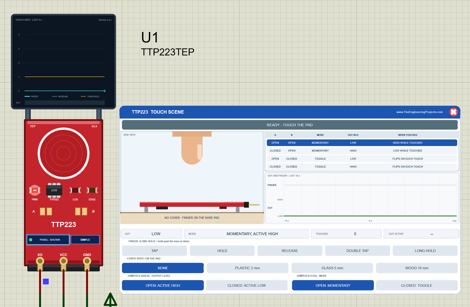
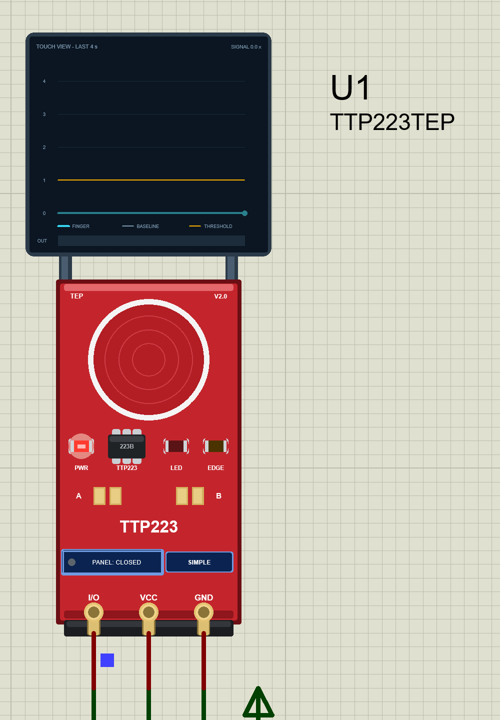
We drew the module as a clean TEP board in the red of the real one: the round touch pad with its white printed ring, the TTP223 chip marked "223B", the LEDs, the solder jumpers A and B and the I/O VCC GND header at the bottom. The real module has its chip, LED and jumpers on the back; our symbol shows everything on one face. Here is U1, the Simple device, after the calibration:
The TOUCH VIEW Screen
Above the board, the TOUCH VIEW screen shows what the chip measures over the last 4 s: the finger's signal (cyan) against the chip's baseline and its threshold (amber, at 1), with an OUT lane at the bottom that turns green while OUT is active. The number at the top right is the signal right now, as a multiple of the threshold. In the image above it is 0.0 x: no finger on the pad.
Pinout
The three pins have the names and the order of the real module:
| Pin | What it does | Demo connection |
|---|---|---|
| I/O | The output, driven HIGH and LOW by the chip | Arduino D2 |
| VCC | Power (2.0 to 5.5 V on a real module) | +5 V terminal |
| GND | Ground | Ground |
LEDs and Indicators
| Indicator | What it shows |
|---|---|
| Round pad | Glows cyan while a touch is reported, blinks amber while the chip calibrates, and glows violet while a finger is ignored; hold the mouse button on it to put a finger on the pad |
| PWR LED (red) | Lit while the module has power (a TEP addition) |
| LED (red) | The module's own LED: lit while OUT is HIGH, as on the real board |
| EDGE LED (amber) | Lights for 0.3 s on every change of OUT (a TEP addition) |
| Jumpers A and B | Gold pads, with a silver solder blob when closed; click one to solder or open it |
| TOUCH VIEW | The signal against the baseline and the threshold, last 4 s (a TEP addition) |
| PANEL / OPEN PANEL, SIMPLE / ADVANCE | The panel button and the device badge |
Only the one red LED is on the real board. The PWR and EDGE LEDs, the board button and the TOUCH VIEW screen are TEP additions that make the simulation easier to follow.
Component Properties
| Property | Meaning | Default |
|---|---|---|
| JUMPERA | OPEN (active HIGH) or CLOSED (active LOW) | OPEN |
| JUMPERB | OPEN (momentary) or CLOSED (toggle) | OPEN |
| COVER | NONE, PLASTIC, GLASS or WOOD | NONE |
| MAXON | The max on time in s, 0 = OFF, up to 100 | 10 |
| RESPONSE | AUTO (low power 220 ms, fast 60 ms) or FAST (always 60 ms) | AUTO |
| CALTIME | The power-on calibration time, 0.1 to 5 s | 0.5 |
| START | UP, or HOLD: a finger on the pad at Run (it becomes the baseline and is ignored until lifted) | UP |
| PANEL | OPEN or CLOSED: the Simple device's panel at Run | OPEN |
A bad value is logged in the Simulation Log and the default is used. The Advance device has no PANEL property; its window has its own "open at Run" setting instead.
TTP223 Simple: The Touch Scene on the Sheet
Beside the Simple board sits the TTP223 TOUCH SCENE panel (on the right of the image above):
| Part | What it does |
|---|---|
| Header, red X | TTP223 TOUCH SCENE; the X closes the panel |
| Banner | The state in words, such as READY - TOUCH THE PAD |
| SIDE VIEW | The module on its spacers on a table, the cover sheet and the finger; the label names the cover and says whether it works |
| Mode table | The four jumper settings with OUT idle and what a touch does; the current one is blue; click a row to set both jumpers |
| OUT AND FINGER - LAST 10 s | The finger on the pad and the OUT level |
| Readouts | OUT, MODE, TOUCHES (since power-on) and OUT ACTIVE (how long OUT is or was active) |
| FINGER | TAP (0.3 s on the pad), HOLD (until RELEASE), RELEASE, DOUBLE TAP and LONG HOLD (past the max on time) |
| COVER SHEET ON THE PAD | NONE, PLASTIC 2 mm, GLASS 5 mm and WOOD 10 mm |
| JUMPER A (AHLB), JUMPER B (TOG) | OPEN: ACTIVE HIGH or CLOSED: ACTIVE LOW; OPEN: MOMENTARY or CLOSED: TOGGLE |
The finger reaches the pad 120 ms after your click, because it travels down first. The banner has a message for every state, from CALIBRATING - DON'T TOUCH THE PAD to MAX ON TIME - RE-CALIBRATED, OUT BACK TO IDLE, LIFT THE FINGER and NO TOUCH DETECTED - THE COVER IS TOO THICK.
HOLD: a Touch Is Detected
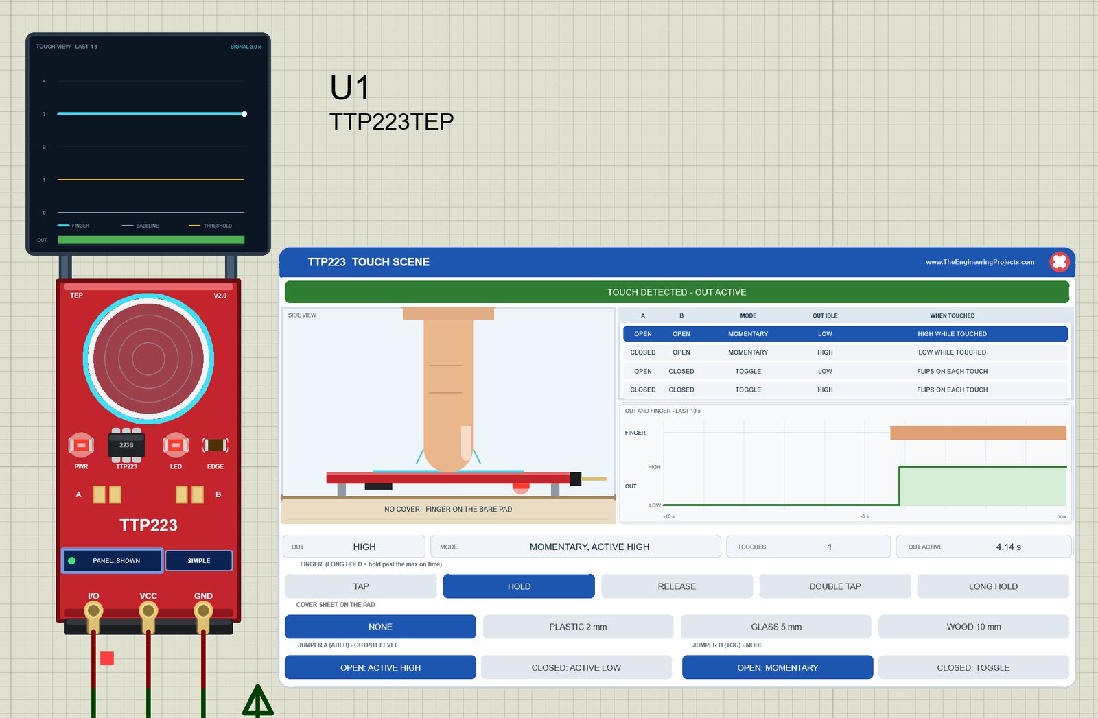
Click HOLD. The finger comes down on the bare pad, cyan touch-field arcs appear around it, and the banner turns green: TOUCH DETECTED - OUT ACTIVE. On the board, the pad glows cyan and the module's LED lights, because OUT is HIGH. The TOUCH VIEW signal jumps to 3.0 x the threshold, far above the amber line, and its OUT lane turns green. In the timeline, the OUT step comes just after the start of the finger bar: that gap is the response time. The OUT ACTIVE readout counts up while you hold (4.14 s in the image). Click RELEASE to lift the finger.
Holding the Board's Pad with the Mouse
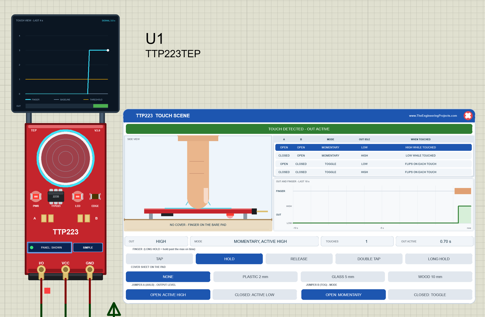
You can also touch the board itself. Press and hold the left mouse button on the round pad, and the finger comes down. The pad glows cyan, the TOUCH VIEW signal steps from 0 to 3.0 x the threshold, the OUT lane turns green, and the banner says TOUCH DETECTED - OUT ACTIVE. The HOLD button lights too, because the finger is held. Let go, and the finger lifts: the banner returns to READY - TOUCH THE PAD, OUT goes LOW, and OUT ACTIVE shows how long the touch lasted (1.40 s in our test).
PLASTIC 2 mm and Jumper B: the Module Toggles Itself
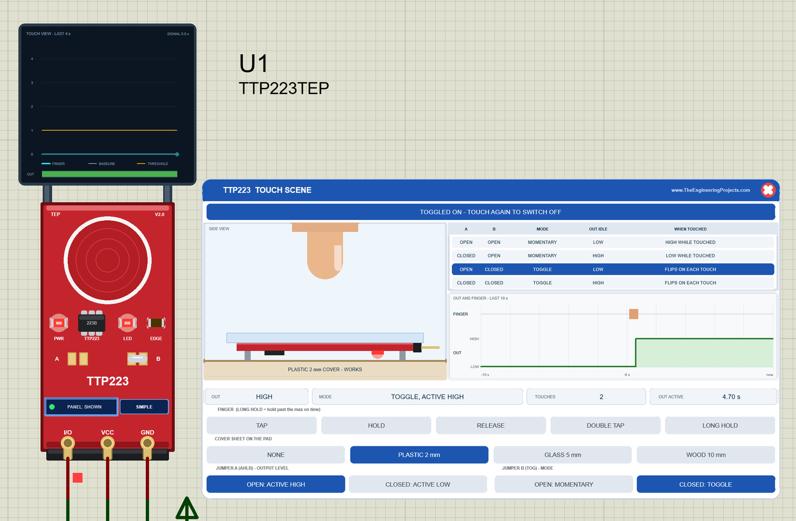
Now click PLASTIC 2 mm and CLOSED: TOGGLE. A plastic sheet lies on the pad in the side view ("PLASTIC 2 mm COVER - WORKS"), the third row of the mode table turns blue, and jumper B on the board gets its silver solder blob. Tap once. The finger goes up again, but OUT stays HIGH, and the banner says TOGGLED ON - TOUCH AGAIN TO SWITCH OFF. The MODE readout says TOGGLE, ACTIVE HIGH, and the TOUCH VIEW shows signal 0.0 x (no finger) with a green OUT lane. The module itself is now a toggle switch: the next touch sends OUT LOW again.
This matters for your sketch. The demo sketch already toggles the lamp on every touch, so with a module that toggles by itself it should follow the pad instead: that is the LAMP FOLLOW command (see below).
Closing the Panel
Click the red X. The panel disappears, the board button says PANEL: CLOSED, and the module keeps working with its pad, LEDs, jumpers and TOUCH VIEW. Click the button to bring the panel back:
TTP223 Advance: The Pop-Up Touch Window
The Advance device keeps only the board on the schematic. Here is U2:
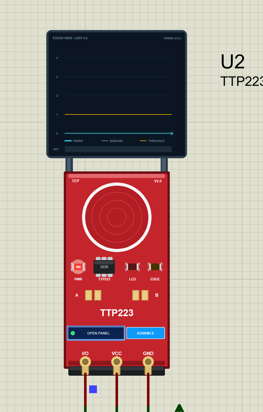
At Run, the "TEP TTP223 Advance" pop-up opens with the look of our TEP Serial Monitor and no Windows title bar: move it by its header, resize or minimise it, and open it again with OPEN PANEL after you close it. The header shows the state (here U2 · OUT LOW; it can also say TOUCHED, CALIBRATING, TESTING or NO POWER), the Touch and Test tabs and the palette (theme), gear (Settings) and ? (Help) icons. A row of chips below the header repeats OUT, the mode, the signal and the touches.
The Touch Page
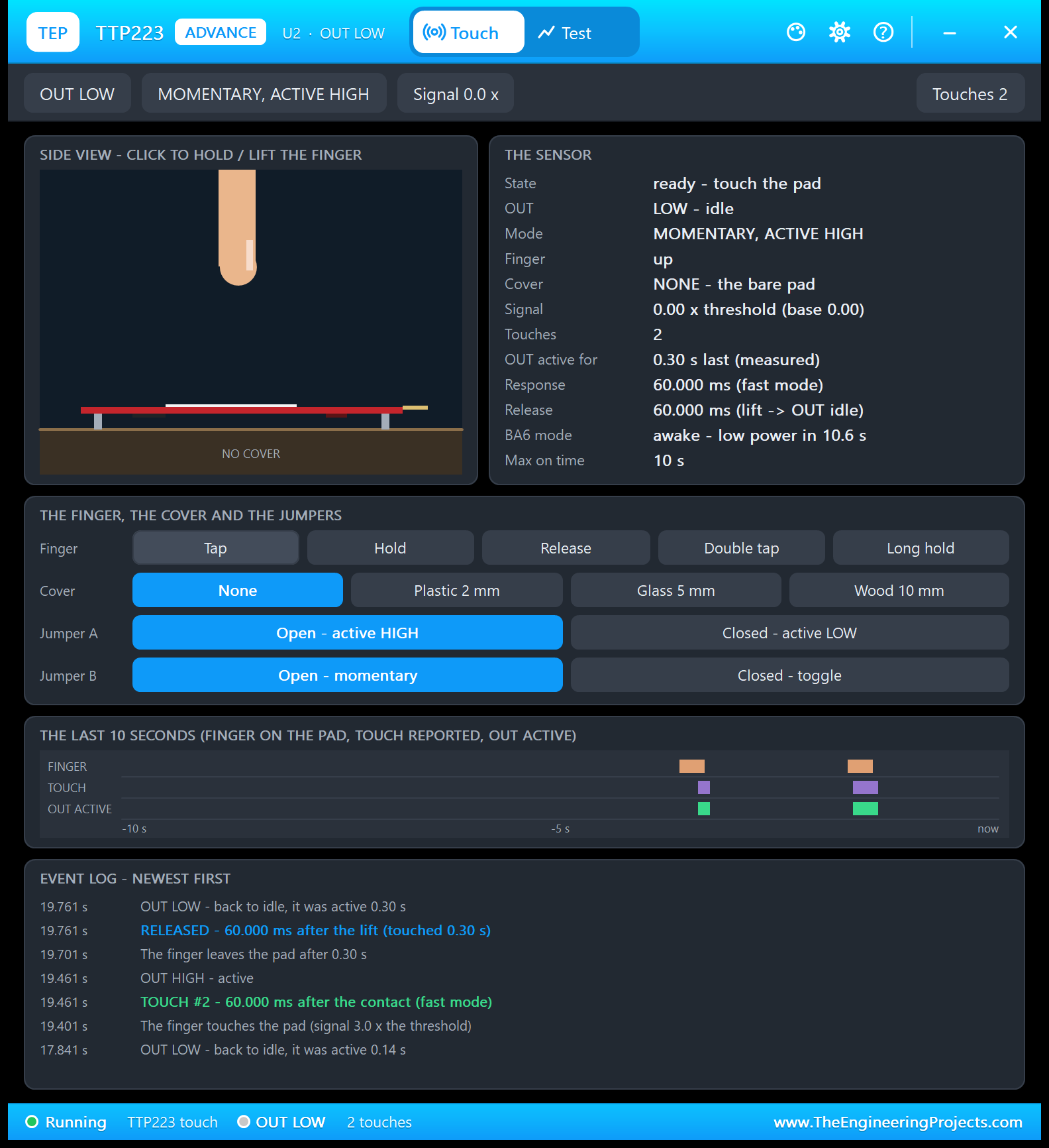
Next to the SIDE VIEW, THE SENSOR card lists the state, OUT, the mode, the finger, the cover, the signal against the threshold, the touches, how long OUT was active, the measured response and release, the BA6 mode (asleep or awake) and the max on time. Below it come the same finger, cover and jumper buttons as on the Simple panel, THE LAST 10 SECONDS in three lanes (finger, touch reported, OUT active) and the EVENT LOG, newest first.
I clicked Tap twice here. Read the event log from the bottom up. The first tap ended at 17.841 s: "OUT LOW - back to idle, it was active 0.14 s". In the second one, the finger touches the pad at 19.401 s with a signal of 3.0 x the threshold, and the chip reports TOUCH #2 - 60.000 ms after the contact (fast mode). The finger leaves after 0.30 s, and the chip reports RELEASED - 60.000 ms after the lift. OUT was active for 0.30 s.
Why was OUT active for only 0.14 s after the first tap? A TAP keeps the finger on the pad for 0.3 s. The first touch woke the sleeping chip and took 220 ms, and the release took 60 ms, so OUT was active for 0.3 - 0.22 + 0.06 = 0.14 s. The second tap came within 12 s, the chip was awake, and OUT followed the finger with 60 ms on both edges: 0.30 s. THE SENSOR card now says "awake - low power in 10.6 s": the 12 s awake window counting down.
Holding the Finger On
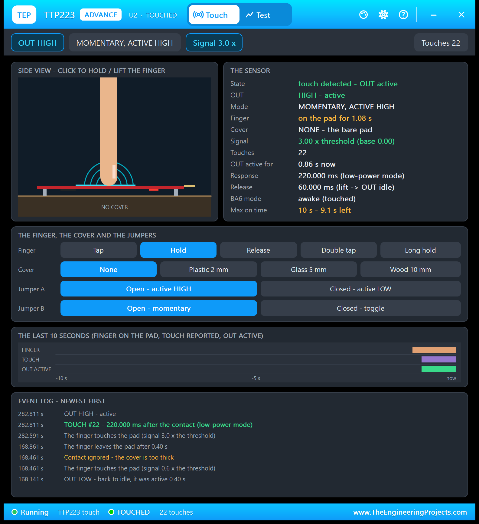
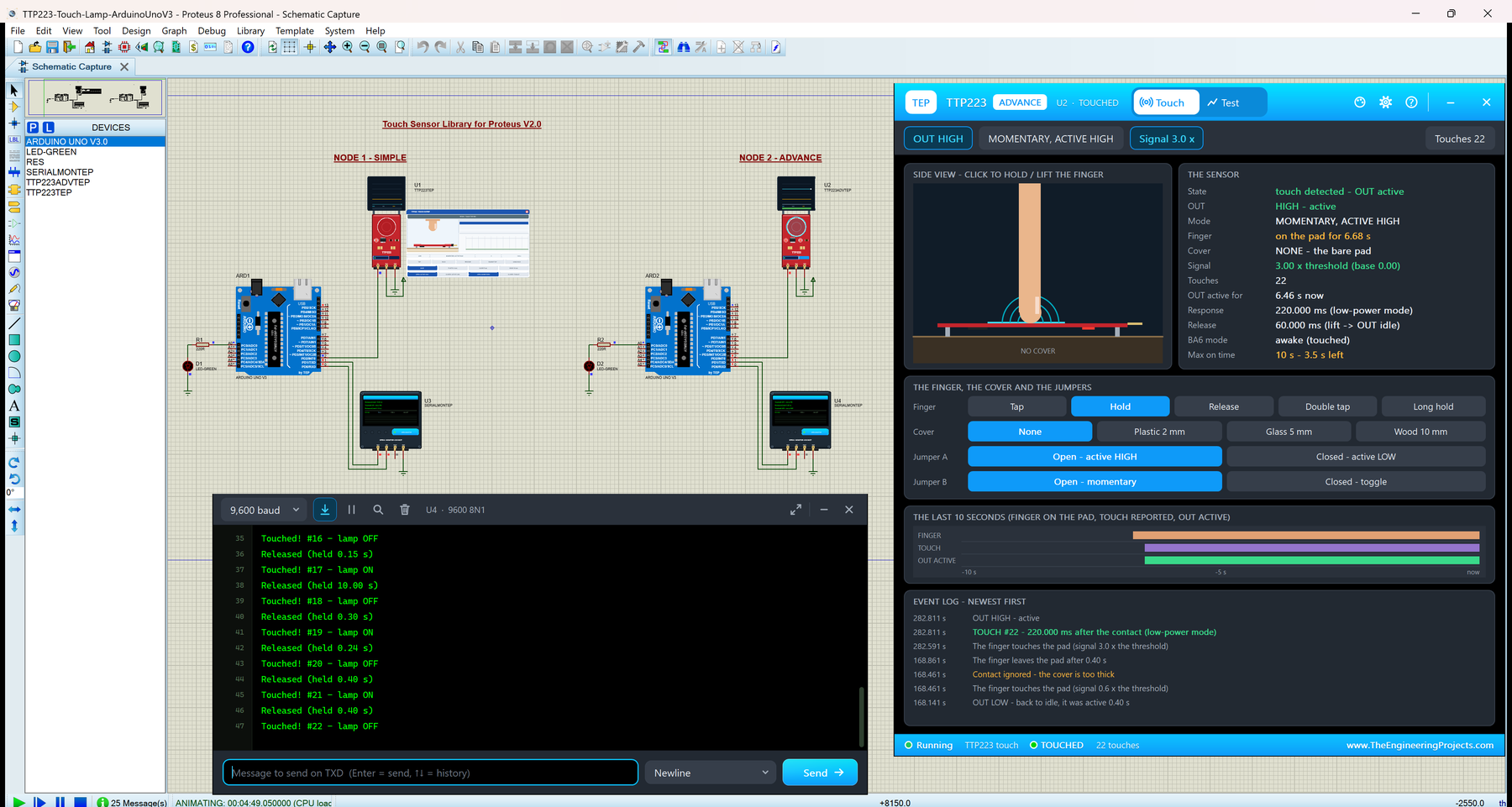
Later in the same run, after the test tools, I clicked Hold. The chip had been quiet for a long time, so it was asleep again: TOUCH #22 - 220.000 ms after the contact (low-power mode). THE SENSOR card turns green: "touch detected - OUT active", the finger on the pad for 1.08 s and OUT active for 0.86 s, exactly 0.22 s less. The max on time counts down: "10 s - 9.1 s left". In the featured image at the top, the same hold has reached 6.68 s, with 3.5 s left.
The older lines in the log come from the Cover sweep below. At 168.461 s, the finger touched the pad through the 10 mm wood with a signal of only 0.6 x the threshold, and the log says "Contact ignored - the cover is too thick".
The Test Page: Four Measured Touch Sensor Test Tools
The four tools on the Test tab move the finger, set the jumpers or the cover, and read only the I/O pin and the model's event log. So every number is what OUT really did, measured with the simulation clock. Each tool puts the jumpers and the cover back when it ends, shows "-" in its tiles until it has a result, and ends with a bold "Good for:" line. All results below come from U2 in our Proteus 8.5 run.
1. Mode Table: What Do Jumpers A and B Do?
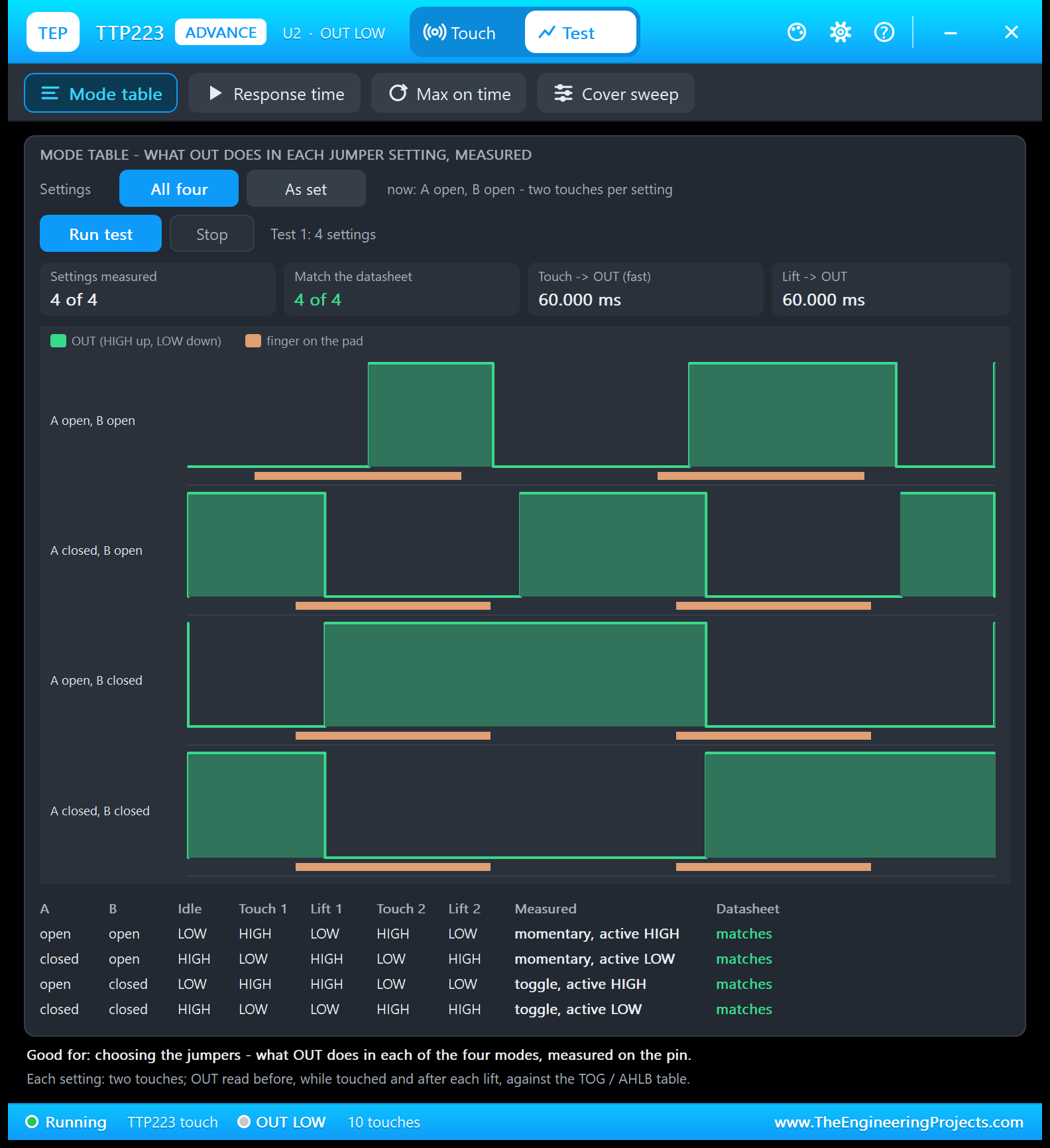
Good for: "choosing the jumpers - what OUT does in each of the four modes, measured on the pin." Choose All four or As set and click Run test. For each setting, the tool makes two touches, reads OUT before, while touched and after each lift, and compares the result with the TOG / AHLB table of the datasheet:
| A / B | Idle | Touch 1 | Lift 1 | Touch 2 | Lift 2 | Measured | Datasheet |
|---|---|---|---|---|---|---|---|
| open / open | LOW | HIGH | LOW | HIGH | LOW | momentary, active HIGH | matches |
| closed / open | HIGH | LOW | HIGH | LOW | HIGH | momentary, active LOW | matches |
| open / closed | LOW | HIGH | HIGH | LOW | LOW | toggle, active HIGH | matches |
| closed / closed | HIGH | LOW | LOW | HIGH | HIGH | toggle, active LOW | matches |
The chart shows the difference at a glance. In the momentary modes, OUT copies the finger bars, inverted when jumper A is closed. In the toggle modes, OUT changes only at each touch and stays there after the lift. The top tiles add the timing: 4 of 4 settings measured and matching, touch to OUT 60.000 ms (fast mode) and lift to OUT 60.000 ms.
2. Response Time: Sleeping vs Awake
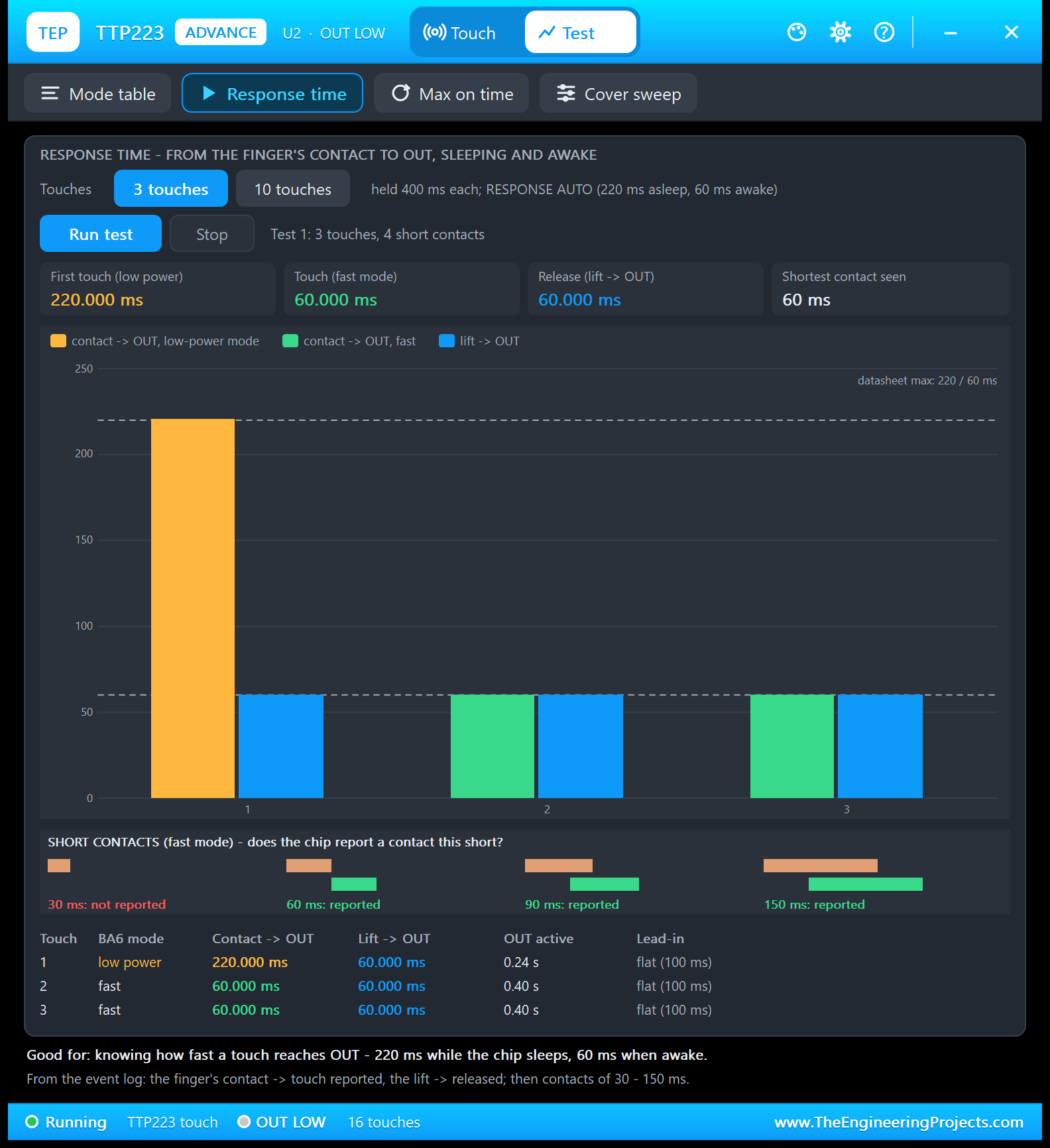
Good for: "knowing how fast a touch reaches OUT - 220 ms while the chip sleeps, 60 ms when awake." Choose 3 or 10 touches, held 400 ms each. The first touch must find the chip asleep, so the tool first waits until 12 s have passed since the last touch, with a countdown. Then it makes the touches after a flat lead-in, and finally it tries four short contacts in fast mode.
| Touch | BA6 mode | Contact to OUT | Lift to OUT | OUT active |
|---|---|---|---|---|
| 1 | low power | 220.000 ms | 60.000 ms | 0.24 s |
| 2 | fast | 60.000 ms | 60.000 ms | 0.40 s |
| 3 | fast | 60.000 ms | 60.000 ms | 0.40 s |
The orange bar reaches the dashed 220 ms line, the datasheet maximum in low-power mode; the green and blue bars sit on the 60 ms line. The OUT active times show the cost of a sleeping chip: 0.24 s instead of 0.40 s for the same 400 ms touch. Under SHORT CONTACTS, 30 ms is not reported, while 60, 90 and 150 ms are, so the shortest contact seen is 60 ms. Do you want 60 ms all the time? Set RESPONSE to FAST.
3. Max On Time: Why a Long Press Drops Out
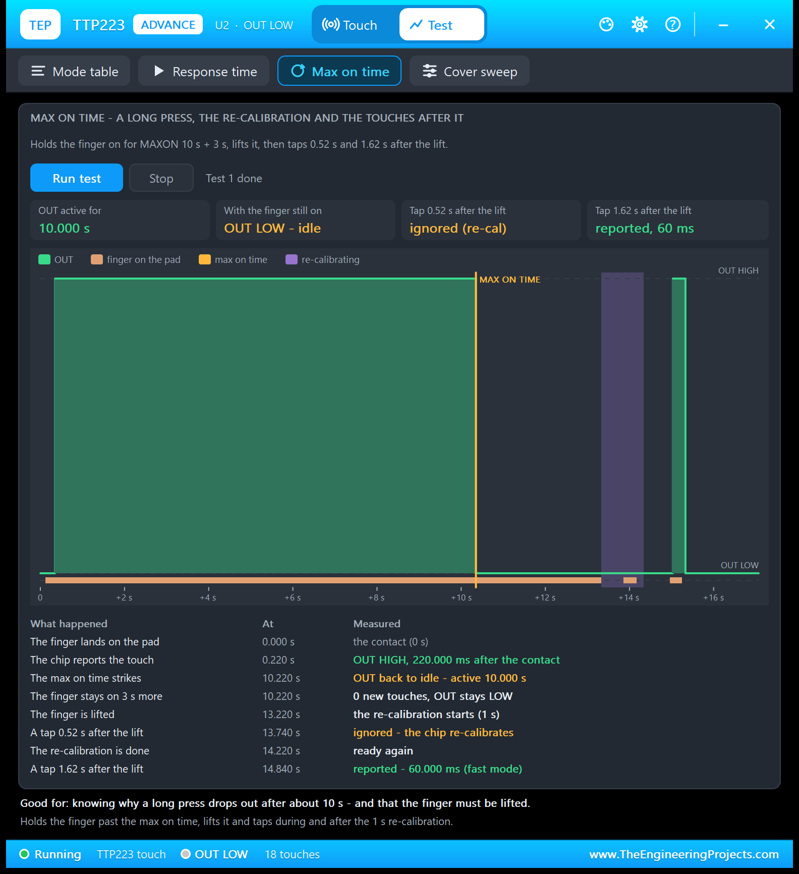
Good for: "knowing why a long press drops out after about 10 s - and that the finger must be lifted." The tool holds the finger on for MAXON 10 s + 3 s, lifts it, and then taps 0.52 s and 1.62 s after the lift. Its table tells the story:
| At | What happened | Measured |
|---|---|---|
| 0.000 s | The finger lands on the pad | The contact |
| 0.220 s | The chip reports the touch | OUT HIGH, 220.000 ms after the contact |
| 10.220 s | The max on time strikes | OUT back to idle - active 10.000 s |
| 10.220 s | The finger stays on 3 s more | 0 new touches, OUT stays LOW |
| 13.220 s | The finger is lifted | The re-calibration starts (1 s) |
| 13.740 s | A tap 0.52 s after the lift | Ignored - the chip re-calibrates |
| 14.220 s | The re-calibration is done | Ready again |
| 14.840 s | A tap 1.62 s after the lift | Reported - 60.000 ms (fast mode) |
The finger was on the pad for 13.2 s, but OUT was active for only 10.000 s. At the max on time, the chip re-calibrated with the finger on it, so the 3 extra seconds gave no new touch. After the lift, the 1 s re-calibration runs (the violet band in the chart), and the tap inside it is ignored. The tap after it is reported in 60 ms, because the chip is still awake. With MAXON 0 (OFF), the tool holds the finger for 15 s, and OUT stays active the whole time.
4. Cover Sweep: Which Panel Still Works?
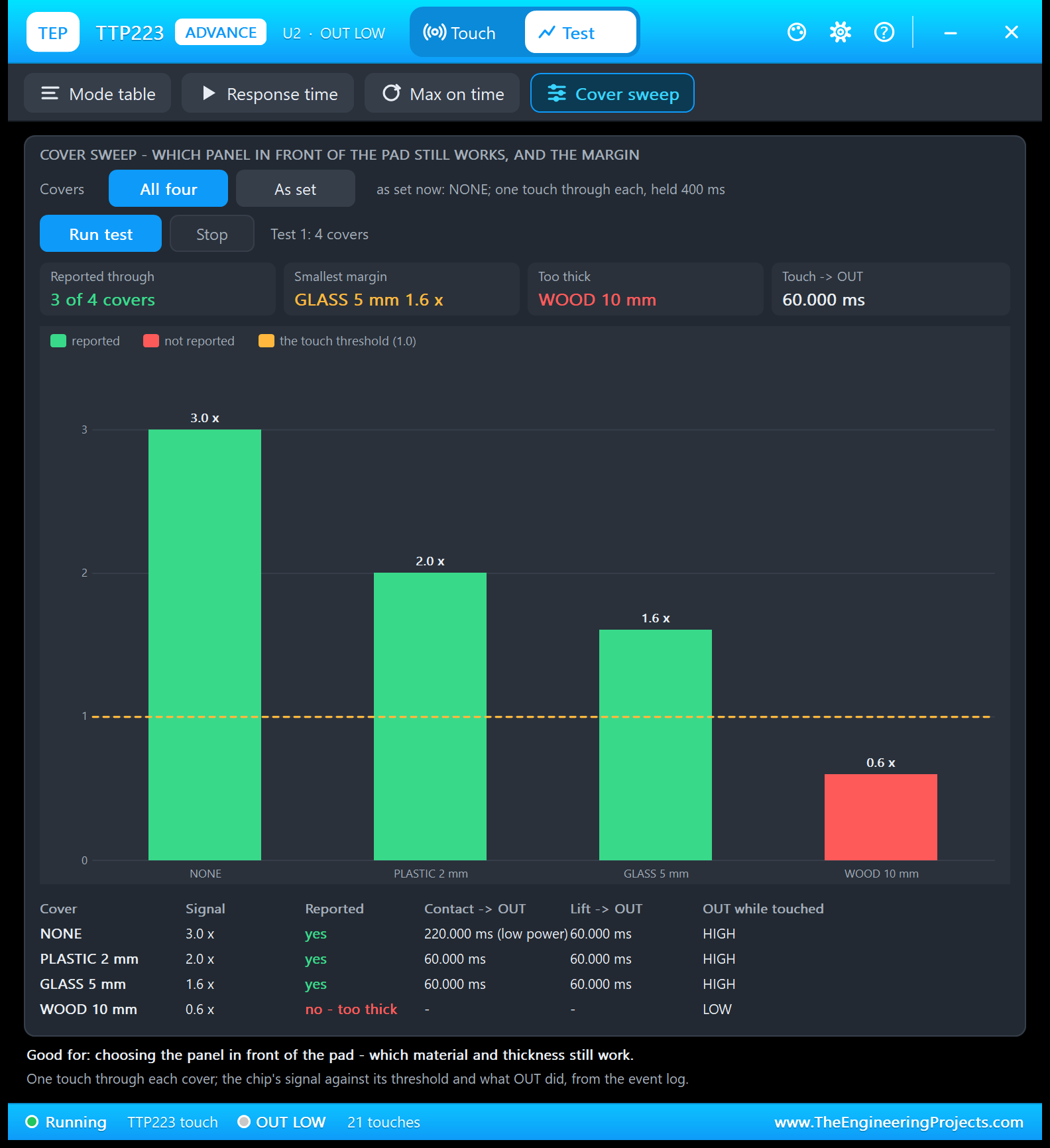
Good for: "choosing the panel in front of the pad - which material and thickness still work." Choose All four or As set. The tool makes one touch through each cover, held 400 ms, and reads the chip's signal against its threshold and what OUT did from the event log:
| Cover | Signal | Reported | Contact to OUT | Lift to OUT | OUT while touched |
|---|---|---|---|---|---|
| NONE | 3.0 x | yes | 220.000 ms (low power) | 60.000 ms | HIGH |
| PLASTIC 2 mm | 2.0 x | yes | 60.000 ms | 60.000 ms | HIGH |
| GLASS 5 mm | 1.6 x | yes | 60.000 ms | 60.000 ms | HIGH |
| WOOD 10 mm | 0.6 x | no - too thick | - | - | LOW |
Every bar above the dashed threshold line (1.0) is reported: 3 of 4 covers. Glass has the smallest margin, 1.6 x, so a thicker glass would be risky. The 10 mm wood gives only 0.6 x: no touch, and OUT stays LOW. The first touch, through no cover, took 220 ms, because the chip had fallen asleep after the Max on time test. The tools refuse to start, with the reason, when the module has no power or another test runs; Response time and Max on time also refuse when the cover is too thick.
Settings and Help
The gear opens Settings: the theme (TEP Dark or Light), the text size (Small, Normal or Large), whether the window opens at Run, and a button that resets the window size.
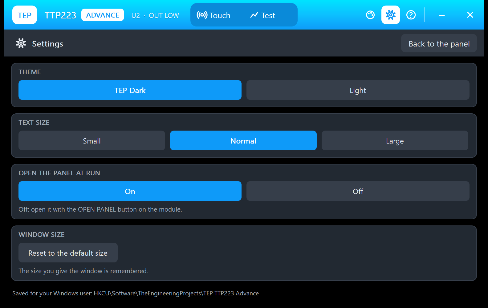
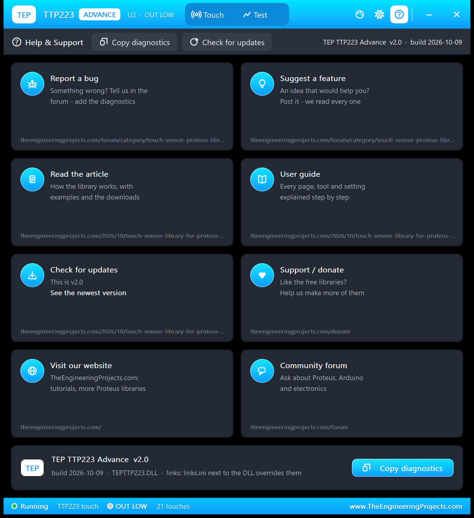
Turn "Open the panel at Run" off, and the window waits until you click OPEN PANEL on the module. The ? icon opens Help & Support: eight cards with their links (the touch sensor board of our forum to report a bug or suggest a feature, this article, a check for updates, donate, our website and the forum), and Copy diagnostics for a bug report: the sensor, the board, the measured values, the events and the test results. A links.ini file next to the DLL can change the links.
TTP223 Touch Lamp with Arduino in Proteus
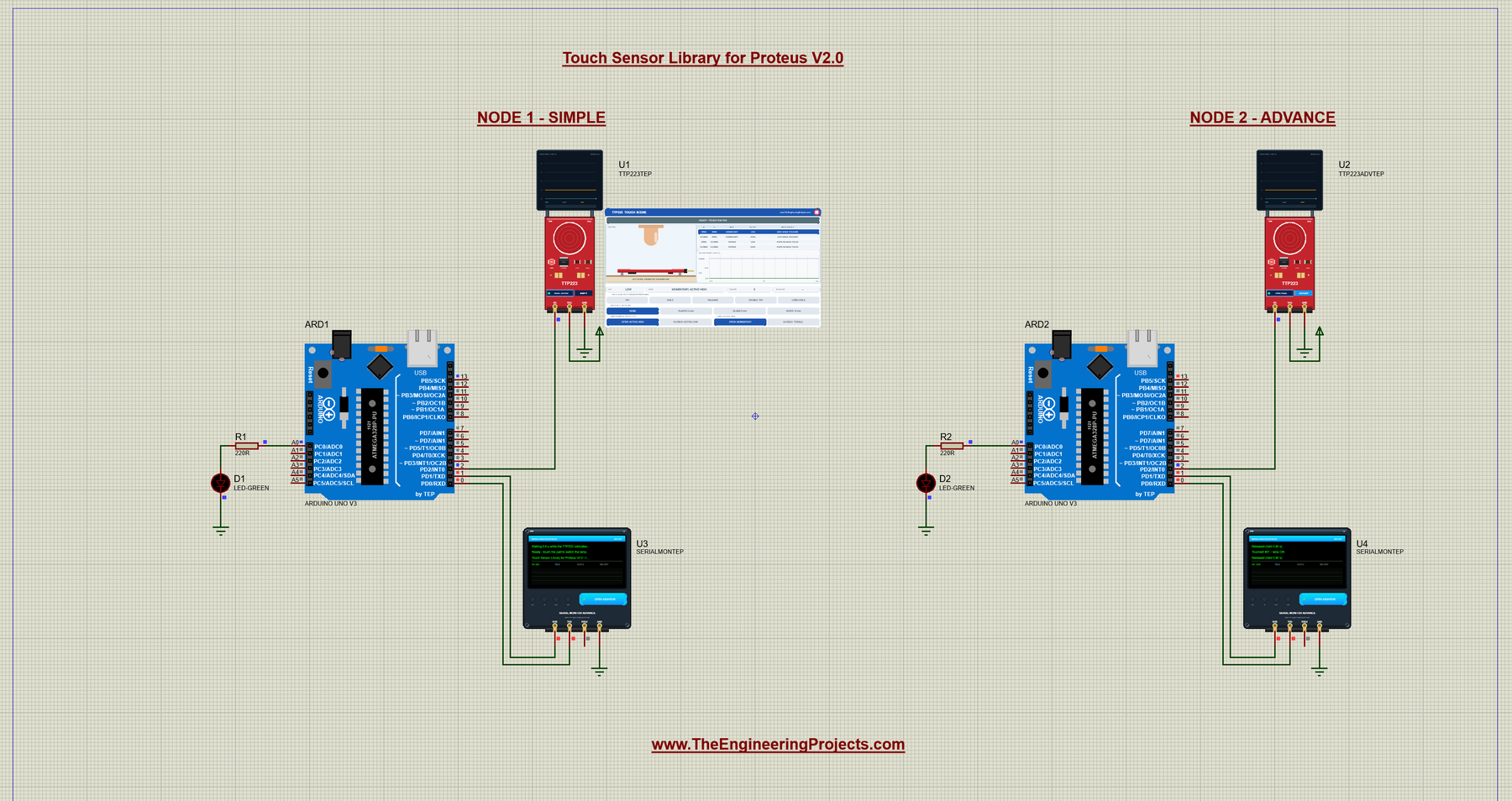
Open TTP223-Touch-Lamp-ArduinoUnoV3.pdsprj from the Proteus Simulation folder, with TTP223_Touch_Lamp.hex and both DLLs beside it. Its two Arduino UNOs from our Arduino Library for Proteus V3.0 run the same HEX file:
- NODE 1 - SIMPLE: UNO 1 (ARD1) with the TTP223 Simple (U1) and Serial Monitor U3.
- NODE 2 - ADVANCE: UNO 2 (ARD2) with the TTP223 Advance (U2) and Serial Monitor U4.
The "lamp" is the UNO's own LED on pin 13. The green LED with its 220 ohm resistor on A0 comes from our demo template; this sketch does not use it.
Wiring
| From | To | Why |
|---|---|---|
| TTP223 VCC / GND | +5 V terminal / ground | Power (the PWR LED lights) |
| TTP223 I/O | Arduino D2 | The touch output: HIGH = touched with the factory jumpers |
| Arduino pin 13 | The UNO's on-board LED | The lamp |
| Serial Monitor RXD / TXD / GND | Arduino D1 (TX) / D0 (RX) / ground | Shows what the Arduino prints, sends what you type |
| Serial Monitor RXD2 | Not connected | I/O is one logic line, and the sketch prints what it sees |
The chip drives I/O HIGH and LOW itself, so the pin needs no pull-up resistor. D0 and D1 are the UNO's hardware serial pins (see our Introduction to Arduino UNO).
The Arduino Code
The sketch is a touch lamp: every touch switches the lamp, and the Serial Monitor reports each touch with a counter and the held time. It uses no Arduino library. First, the two pins:
const int TOUCH_PIN = 2;      // TTP223 I/O pin
const int LAMP_PIN = 13;      // the "lamp": the UNO's on-board LED
In setup(), I/O becomes an input, the lamp starts off, and the sketch waits 0.6 s for the chip's calibration before it says Ready. The last start line names this library version:
void setup() {
  pinMode(TOUCH_PIN, INPUT);  // the TTP223 drives the pin HIGH and LOW itself, no pull-up needed
  pinMode(LAMP_PIN, OUTPUT);
  digitalWrite(LAMP_PIN, LOW);
  Serial.begin(9600);
  Serial.println("TTP223 Touch Lamp - The Engineering Projects");
  Serial.println("Waiting 0.6 s while the TTP223 calibrates (don't touch the pad)...");
  delay(600);
  Serial.println("Ready - touch the pad to switch the lamp.");
  Serial.println("Touch Sensor Library for Proteus V2.0 - type HELP for the commands.");
}
One function reads the pad. With the factory jumpers, HIGH means touched; after the ACTIVE LOW command, LOW means touched:
bool readTouched() {
  bool high = digitalRead(TOUCH_PIN) == HIGH;    // HIGH = finger on the pad (default)
  return activeLow ? !high : high;
}
The loop reads the commands first, so that ACTIVE LOW or ACTIVE HIGH takes effect before the pin is read:
void loop() {
  readCommands();                                  // (first: ACTIVE LOW / HIGH changes what the pin means)
  bool touched = readTouched();
When the finger lands, the sketch counts the touch, switches the lamp (in FOLLOW mode, it switches it on) and notes the time:
  if (touched && !wasTouched) {                    // the finger just landed
    touchCount++;
    setLamp(followMode ? true : !lampOn);          // switch the lamp (FOLLOW: on)
    touchStart = millis();
    Serial.print("Touched! #");
    Serial.print(touchCount);
    Serial.print(" - lamp ");
    Serial.println(lampOn ? "ON" : "OFF");
  }
When the finger is lifted, the sketch measures how long the pad was held, keeps the longest time and prints it. Then it checks the pad again after 1 ms, about 1000 times a second:
  if (!touched && wasTouched) {                    // the finger was lifted
    lastHeld = millis() - touchStart;
    if (lastHeld > longestHeld) longestHeld = lastHeld;
    if (followMode) setLamp(false);
    Serial.print("Released (held ");
    printHeld(lastHeld);
    Serial.println(")");
  }

  wasTouched = touched;
  delay(1);                                        // check the pad about 1000 times a second
}
The held time is measured on the I/O pin, so it equals the time OUT was active, not the time your finger was on the pad. printHeld() rounds it to 0.01 s:
void printHeld(unsigned long ms) {
  ms += 5;
  Serial.print(ms / 1000);
  Serial.print('.');
  unsigned long hundredths = (ms % 1000) / 10;
  if (hundredths < 10) Serial.print('0');
  Serial.print(hundredths);
  Serial.print(" s");
}
LAMP FOLLOW makes the lamp copy the pad, which is what you need when jumper B is closed and the module toggles by itself:
  } else if (strcmp(text, "LAMP FOLLOW") == 0) {
    followMode = true;
    setLamp(wasTouched);
    Serial.println("Lamp mode: FOLLOW - the lamp is on while the pad is touched.");
ACTIVE HIGH and ACTIVE LOW change what the pin means. The sketch reads the pad again at once, so the change itself never prints a "Touched!":
  } else if (strcmp(text, "ACTIVE HIGH") == 0 || strcmp(text, "ACTIVE LOW") == 0) {
    activeLow = text[7] == 'L';
    wasTouched = readTouched();                  // the new meaning of I/O now - no "Touched!" for it
    if (followMode) setLamp(wasTouched);
HELP prints three short lines that fit the Serial Monitor's Simple interface:
void printHelp() {
  Serial.println("Commands: HELP, STATUS, RESET, LAMP TOGGLE / FOLLOW, ACTIVE HIGH / LOW");
  Serial.println("  LAMP TOGGLE: each touch switches the lamp; FOLLOW: on while touched");
  Serial.println("  ACTIVE LOW: I/O LOW means touched (jumper A closed on the module)");
}
To change the sketch, export a new HEX file and load it into both UNOs; see How to get the HEX file from Arduino. New to Arduino? Start with our Arduino Tutorial for Beginners.
Serial Monitor Commands
| Command | What it does |
|---|---|
| HELP | The command list (three lines) |
| STATUS | Two lines: the pad, I/O, the lamp, the touches, the held times (last and longest), the active level and the lamp mode |
| RESET | The touch counter back to 0 |
| LAMP TOGGLE | Each touch switches the lamp (at start) |
| LAMP FOLLOW | The lamp is on while the pad is touched (for jumper B closed) |
| ACTIVE HIGH | I/O HIGH means touched (jumper A open, at start) |
| ACTIVE LOW | I/O LOW means touched (jumper A closed) |
Nothing is printed periodically: the sketch prints a line only when something happens or when you send a command, and every line is shorter than 80 characters. After a LONG HOLD, for example, STATUS answers "Status: pad free, I/O LOW, lamp ON, touches: 3" and "held: last 10.00 s, longest 10.00 s; active HIGH; lamp TOGGLE" (the README's example). An unknown command gets "Unknown command: FOO - type HELP".
How to Run the Demo
- Press Run. Both Serial Monitors (9600 baud) and U2's pop-up open, and U3 and U4 print the four start lines. The pads blink amber while the chips calibrate; then the banner says READY.
- On U1's panel, click TAP, and TAP again within 12 s: the first touch takes 220 ms, the second only 60 ms. Then hold the board's round pad with the mouse, and try DOUBLE TAP, LONG HOLD, the covers and a row of the mode table.
- Close U1's panel with its red X, and open it again with PANEL: CLOSED on the board.
- On U2, use the Touch page, then the four tools on the Test tab. If you close jumper A, send ACTIVE LOW on U4, so that the sketch reads the pad right.
- Close U2's window and open it again with OPEN PANEL.
Touch Sensor Proteus Simulation Results
The Serial Monitor in Its Simple Interface
Both monitors in this demo run in the Simple interface of our TEP Serial Monitor, as in every monitor screenshot here. Only the log, the send box and one slim toolbar row stay visible (baud rate, follow, pause, search and clear), so the window stays small.
- Switch to it: right-click the log and choose Simple interface, or press Ctrl+Shift+U.
- Back to the full view: click the corner button (the expand arrows at the top right), press Esc or Ctrl+Shift+U, or right-click and choose Full interface.
- Your choice is remembered.
Type commands such as STATUS or LAMP FOLLOW in the send box and press Enter; the quick buttons come back with the full view. Read all about the monitor in TEP Serial Monitor Advance for Proteus.
Start-Up and the First Two Taps
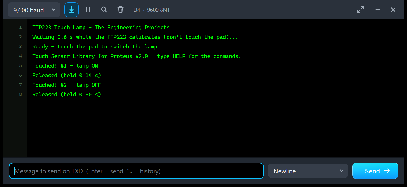
TTP223 Touch Lamp - The Engineering Projects
Waiting 0.6 s while the TTP223 calibrates (don't touch the pad)...
Ready - touch the pad to switch the lamp.
Touch Sensor Library for Proteus V2.0 - type HELP for the commands.
Touched! #1 - lamp ON
Released (held 0.14 s)
Touched! #2 - lamp OFF
Released (held 0.30 s)
These are the two taps of the Touch page above, now seen by the Arduino on UNO 2. The held times are the measured OUT active times: 0.14 s for the first tap, which woke the sleeping chip, and 0.30 s for the second. The lamp on pin 13 went on with the first touch and off with the second.
The Test Tools, Seen by the Arduino
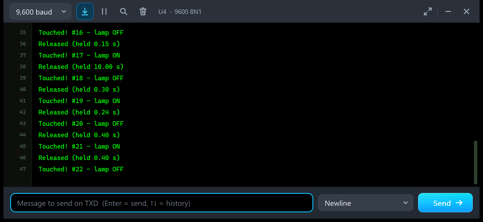
Touched! #16 - lamp OFF
Released (held 0.15 s)
Touched! #17 - lamp ON
Released (held 10.00 s)
Touched! #18 - lamp OFF
Released (held 0.30 s)
Touched! #19 - lamp ON
Released (held 0.24 s)
Touched! #20 - lamp OFF
Released (held 0.40 s)
Touched! #21 - lamp ON
Released (held 0.40 s)
Touched! #22 - lamp OFF
The test tools move the finger, so the Arduino sees their touches too, and every held time matches a tool's measurement:
- #16, held 0.15 s: the 150 ms short contact of the Response time tool.
- #17, held 10.00 s: the Max on time tool. The finger stayed 3 s longer, but OUT was active for 10 s only.
- #18, held 0.30 s: its tap 1.62 s after the lift. The tap at 0.52 s gave no line, because the chip ignored it.
- #19 to #21, held 0.24, 0.40 and 0.40 s: the Cover sweep through no cover (the chip was asleep: 220 ms), plastic and glass. The 10 mm wood gave no line at all.
- #22: the Hold of the featured image, with the finger still on.
This is the strongest test of the library: the times the Arduino measured on its pin agree with the model's own event log and with the test tools.
Troubleshooting
- The first touch takes longer than the next ones: correct. The sleeping chip needs up to 220 ms; RESPONSE FAST makes it 60 ms always.
- OUT drops back while the finger is still on the pad: the max on time (MAXON, 10 s). The chip re-calibrates; lift the finger and touch again.
- A touch is ignored right after Run: the chip calibrates for 0.5 s. A finger on the pad at that time (START HOLD) is ignored until it is lifted.
- No touch with WOOD 10 mm: the cover is too thick (a signal of 0.6 x the threshold).
- The sketch prints "Touched!" when you close jumper A: it still reads HIGH as touched. Send ACTIVE LOW.
- With jumper B closed, the lamp changes only on every second touch: the module already toggles. Send LAMP FOLLOW.
- The Test tab says "Cannot start: ...": the message gives the reason (no power, another test is running, or the cover is too thick).
- The part is not simulated, no panel or no monitor window: TEPTTP223.DLL or TEPSERIALMON.DLL is missing from MODELS and the project folder; click OPEN MONITOR on a closed monitor.
- The Advance pop-up does not appear: click OPEN PANEL on the board, or turn "Open the panel at Run" back on in Settings.
- The red X does not close the Simple panel: the design holds an older symbol. Replace TEPTTP223.LIB, delete TEPTTP223.IDX and pick the part again.
Things to Know Before Using a Real TTP223 Module
The demo sketch uses no library, so it runs unchanged on a real UNO with a real module. Keep in mind:
- Supply: the module works from 2.0 to 5.5 V, and I/O swings between 0 V and VCC, so it suits both 3.3 V and 5 V boards. Check the pin order on your board's silkscreen.
- No pull-up: I/O is the chip's own CMOS output; connect it straight to a digital pin.
- Jumpers: A and B are solder pads on the back. Set them with the power off (in the model, a change applies at once).
- Max on time: users report the output dropping after 7 to 12 s of continuous touch; it is not in the BA6 datasheet.
- Covers: a few mm of plastic or glass work; keep metal away from the pad. Test your own panel, because our cover factors are estimates.
Limitations of the Simulation
- Not modelled: the analog capacitance and the chip's sampling, the effect of the supply voltage on the timing (the model uses the 3 V maximum values), the 4 s re-calibration cycle while not touched (only the 1 s re-calibration after an ignored finger), the finger's size and position on the pad, water or noise on the pad, and real cover materials beyond the four presets.
- The model is our own implementation, written from the published TTP223 datasheet and module descriptions; it contains no third-party code. The HEX file contains the Arduino AVR core 1.8.6, which includes LGPL-licensed code; its source code is on GitHub.
- Speed: about 0.6 x real time for the two-UNO demo (24.5 s simulated in 41.1 s, with U2's window open on the Test page, U1's panel animating and both monitors open).
- Tested in Proteus 8.5 in October 2026 (the demo, both panels, the four tools, the board pad held with the mouse and every screenshot here) and with 1,440 automatic PC checks, all passed, 29 of them with the real demo sketch on two UNOs. Proteus 7 is not supported.
Do you need more digital sensors for the same kind of sketch? See our Infrared Sensor Library for Proteus V2.0 for obstacles and our PIR Sensor Library for Proteus V4.0 for motion. For a knob instead of a touch pad, try our Rotary Encoder Library for Proteus.
So, that was all about the Touch Sensor Library for Proteus V2.0. I hope the live TTP223 board, the touch scene, the event log and the four test tools make the touch module easy to understand, so your touch lamp or hidden switch works the first time you wire a real module. If you use the Touch Sensor Library for Proteus in a project, please share your feedback in the comments or in our forum, and if you have any questions, ask in the comments and I will help you out. Till the next tutorial, take care and have fun!
Comments
0