


nRF9151 DK Library for Proteus: LTE-M and GNSS Tracker Simulation


Hello friends, I hope you all are doing great. Today, I am going to share the nRF9151 DK Library for Proteus, so you can run a cellular IoT simulation of Nordic Semiconductor's LTE-M and NB-IoT development kit. The nRF9151 puts a processor, a cellular modem and GNSS into one small package, and its DK is where research groups and product teams build trackers, meters and sensors that talk to the world without Wi-Fi. With this library it runs your Arduino sketch in Proteus 8.5, its modem registers on a network, sends and receives SMS and finds its position, and its four LEDs and two buttons work with a click.
nRF9151 DK Library for Proteus
Latest version: V1.0 (November 2026, this tutorial)
Helping Tools
- Laptop WiFi Monitor: a laptop on the Wi-Fi of your design: a browser, a TCP / UDP terminal and ping
- Mobile WiFi Monitor: a smartphone that opens the pages of your board and sends it commands
- Serial Monitor Advance: a serial terminal window for the UART of your board
For the demo we built an LTE-M GNSS cold-chain tracker, the kind of device that rides with vaccines or fresh food in a truck. A BME280 watches the load's temperature, the tracker reports where it is by SMS, answers the owner's commands, and sends a WARM alarm the moment the load gets warmer than 8 C. The board's own Phone window is the owner's phone, and it also sets the GNSS scene: parked, driving, or no fix at all.
NOTICE: Proteus has no nRF9151 model, so our team has put a lot of effort into building this board ourselves: the DK's Arduino header, the LEDs, the buttons and the modem with its SMS and GNSS are all our own model, and your sketch compiles with our free TEP Boards for Proteus add-on. Your feedback is the fuel that keeps us going, so please tell us what you think in the comments below. And if our free libraries help you, you can buy us a coffee. So, let's get started with the nRF9151 DK Library for Proteus:
What is the nRF9151 DK?
The nRF9151 DK (its board number is PCA10171) is Nordic Semiconductor's development kit for the nRF9151 system-in-package. It keeps the familiar shape of Nordic's DKs, with an Arduino Uno header, an on-board debugger with its own USB port, four LEDs, two buttons and two slide switches. What makes it different sits at the right end: the shielded nRF9151, a nano-SIM holder, an LTE antenna and a ceramic GNSS patch antenna. The kit ships with SIM cards for free trial data, so a new board can reach a real network on the first day.
| Feature | The real nRF9151 DK | In the library |
|---|---|---|
| Processor | Arm Cortex-M33, 64 MHz, 1 MB flash, 256 KB RAM | your Arduino sketch |
| Modem | LTE-M, NB-IoT and DECT NR+, with SMS | registration and SMS (text mode) |
| Position | GNSS (GPS and others) inside the SiP | GNSS fixes from the phone's scene |
| SIM | nano-SIM holder, eSIM footprint | drawn |
| On the board | four LEDs, two buttons, two switches, RESET | LEDs and buttons animated, switches drawn |
LTE-M and NB-IoT in a Nutshell
Ordinary 4G is built for phones: lots of data, high power, always ready. The cellular networks also offer two slimmer flavours for machines. LTE-M moves a modest amount of data, keeps working while the device travels from cell to cell, and even allows voice on some networks. NB-IoT is narrower still: tiny messages, deep indoor coverage in basements and meter cupboards, and very low power. Both can sleep for hours between reports with power saving modes such as PSM and eDRX, which is how a tracker or a water meter lasts years on a battery. The nRF9151 speaks both, and the newer DECT NR+ for private mesh networks too.
Why a System-in-Package?
A cellular design used to mean a processor, a separate modem module, a GNSS receiver, a power circuit and a lot of careful radio layout. The nRF9151 is a system-in-package: all of that sits under one metal shield of about 11 x 12 mm, already certified for the networks. The product team only adds a SIM, the antennas and the sensors, and writes the application. That is why this one part appears in so many research prototypes and commercial trackers, and why its DK is worth learning.
AT Commands: How a Program Talks to a Modem
Every cellular modem, from the oldest GSM module to the nRF9151, is driven by AT commands: short text lines such as AT+CEREG? (am I registered?) or AT+CMGS (send an SMS), each answered by OK or an error. The modem also speaks up on its own with lines called URCs, for example +CMT when an SMS arrives. On the real nRF9151 the application sends these commands through Nordic's modem library; in our library the board gives your sketch the same conversation on SerialModem, so you can watch every command and answer.
Features of the nRF9151 DK Library for Proteus
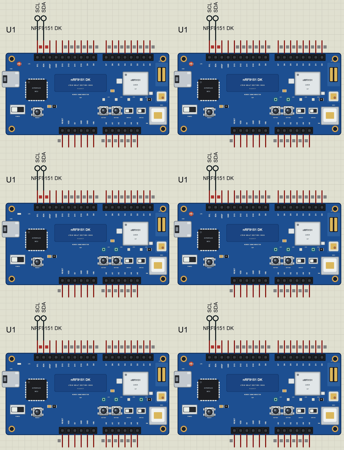
- The board as it looks: the blue DK with its headers, the shielded nRF9151, the nano-SIM holder, the LTE and GNSS antennas, the interface MCU and USB port, four LEDs, two buttons and two switches, drawn compact, with our small TEP signature.
- Your sketch: a .hex for "Nordic nRF9151 DK (TEP Proteus)" with the DK's pin names,
SerialModemandMODEM_ON. - A working modem: registration, SMS in both directions and GNSS positions, with an LTE LED that shows the network light.
- A phone at the other end: the board's own Phone window receives the SMS, sends them with four quick keys, and sets the GNSS scene.
- Real LEDs and buttons: the LEDs light when HIGH, as on the real DK; the buttons are clicked on the board.
- A complete package: about 3.7 MB with the part, the add-on, the BME280 library and the demo, without the source code of the models.
The nRF9151 DK in Proteus Simulation
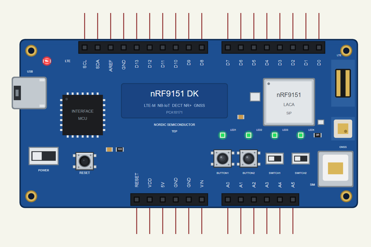
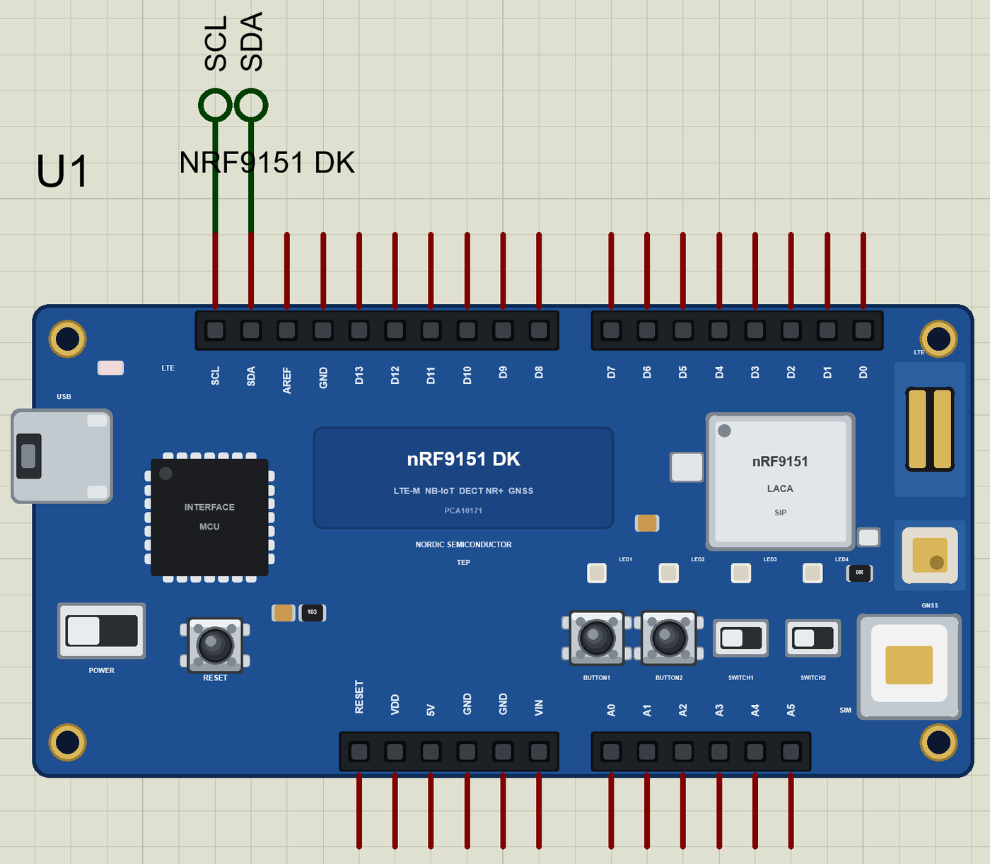
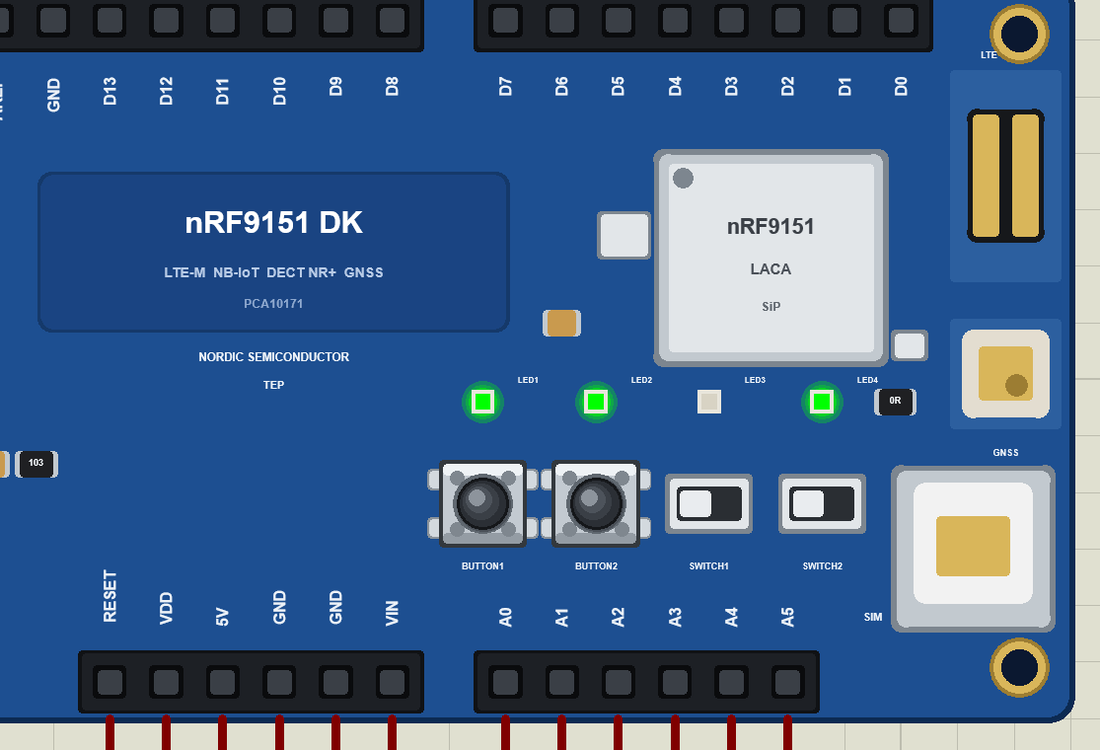
Search NRF9151 in Pick Devices; the device is in TEPNRF9151DK.LIB (Microprocessor ICs, Cellular Boards), with the prefix U. Click the USB port for the serial monitor, and the SiP for the modem's own window. The headers follow the real silk, and the board shares its pin numbering with our nRF52840 DK Library for Proteus.
The Pins
| Pins | What the library does with them |
|---|---|
| D0, D1 | GPIO (Serial1 is the modem's AT interface) |
| D2 to D13 | GPIO, PWM with analogWrite, attachInterrupt |
| D10 to D13 | SPI: SS, MOSI, MISO, SCK |
| A0 to A5 | analogRead 0 to 1023 for 0 to 3.3 V, or GPIO |
| SDA, SCL | Wire, the I2C bus |
| VDD, 5V, GND, RESET | the supply and the reset |
The LEDs, the Buttons and the Modem Pins
LED1 to LED4 light when the pin is HIGH; on the real DK they sit on P0.00, P0.01, P0.04 and P0.05. BUTTON1 and BUTTON2 are the two push buttons (P0.08 and P0.09), and they read LOW while you hold them; the two slide switches are drawn but not modelled. SerialModem is the modem's AT interface at 115200 baud, and MODEM_ON starts the modem. The small LTE LED near the corner shows the modem's network light, so you can see the modem working without any window open.
Download nRF9151 DK Library for Proteus
Click the button below to download nRF9151-DK-Library-for-Proteus-v1.0.zip (about 3.7 MB, without the source code of the models):
nRF9151 DK Library for Proteus V1.0- README.txt: installation, the demo, the pins, the properties, troubleshooting and the limits.
- Proteus Library Files:
TEPNRF9151DK.LIBand the demo'sTEPBME280.LIB, plusTEPMOBILE.LIBandTEPLAPTOP.LIBfor your own designs. - Proteus Model Files:
TEPNET.DLL(the board with its modem) andTEPBME280.DLL. - Arduino Code: the demo sketch and the TEP Boards for Proteus add-on 1.62.0.
- Proteus Simulation: the demo project, its HEX file and a copy of the DLL.
No Proteus yet? Read How to Download and Install Proteus 7 and 8. New to libraries? Follow How to Install a New Library in Proteus.
How to Install nRF9151 DK Library for Proteus
- Close Proteus and extract the whole zip file, for example to your Desktop.
- Copy the files from Proteus Library Files into the LIBRARY folder of Proteus.
- Copy
TEPNET.DLLfrom Proteus Model Files into the MODELS folder, replacing an older one. - Delete
TEPNRF9151DK.IDXfrom the LIBRARY folder if it is there. - For your own sketches, copy Arduino Code\TEP Boards for Proteus\hardware into your Arduino sketchbook (Documents\Arduino) and restart the Arduino IDE; the board is Nordic nRF9151 DK (TEP Proteus). Install Adafruit BME280 and Adafruit Unified Sensor from the Library Manager.
- Start Proteus, press P and search for NRF9151.
Demo: an LTE-M GNSS Cold-Chain Tracker in Simulation
Vaccines, insulin and fresh food must stay between 2 and 8 C all the way from the factory to the shelf, the so-called cold chain. A cold-chain tracker answers two questions for its owner: where is the load, and is it still cold? It has to answer from anywhere, without Wi-Fi, and for weeks on a battery. That is exactly the job LTE-M and GNSS were made for, with SMS as the simplest possible way to talk to a person.
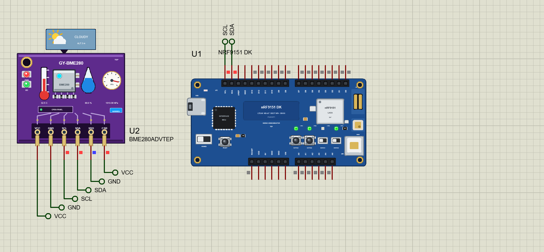
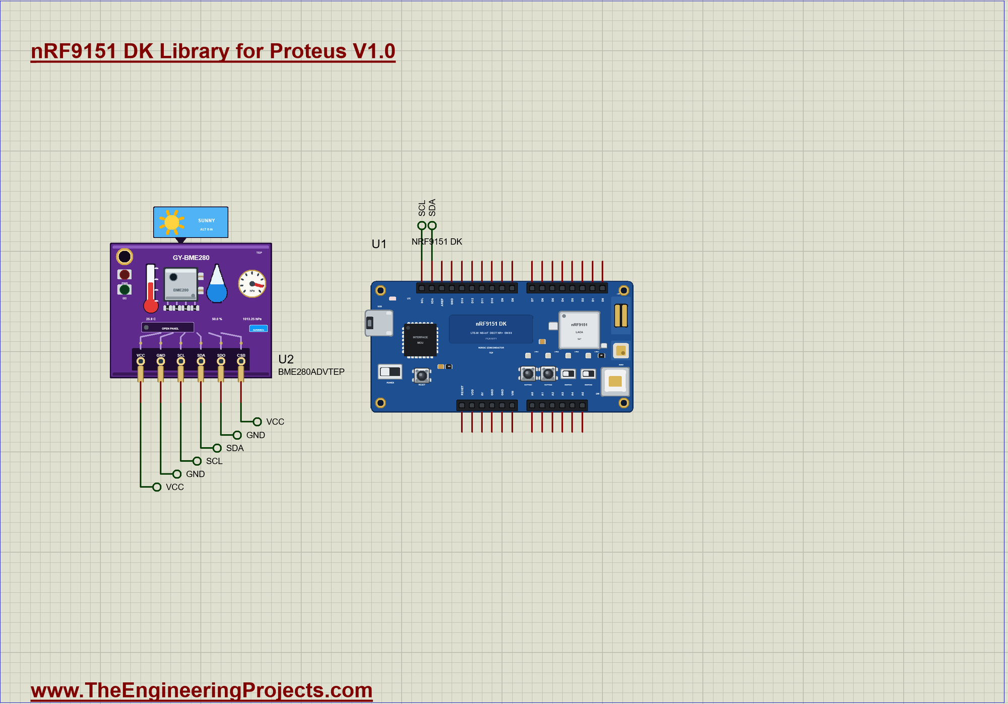
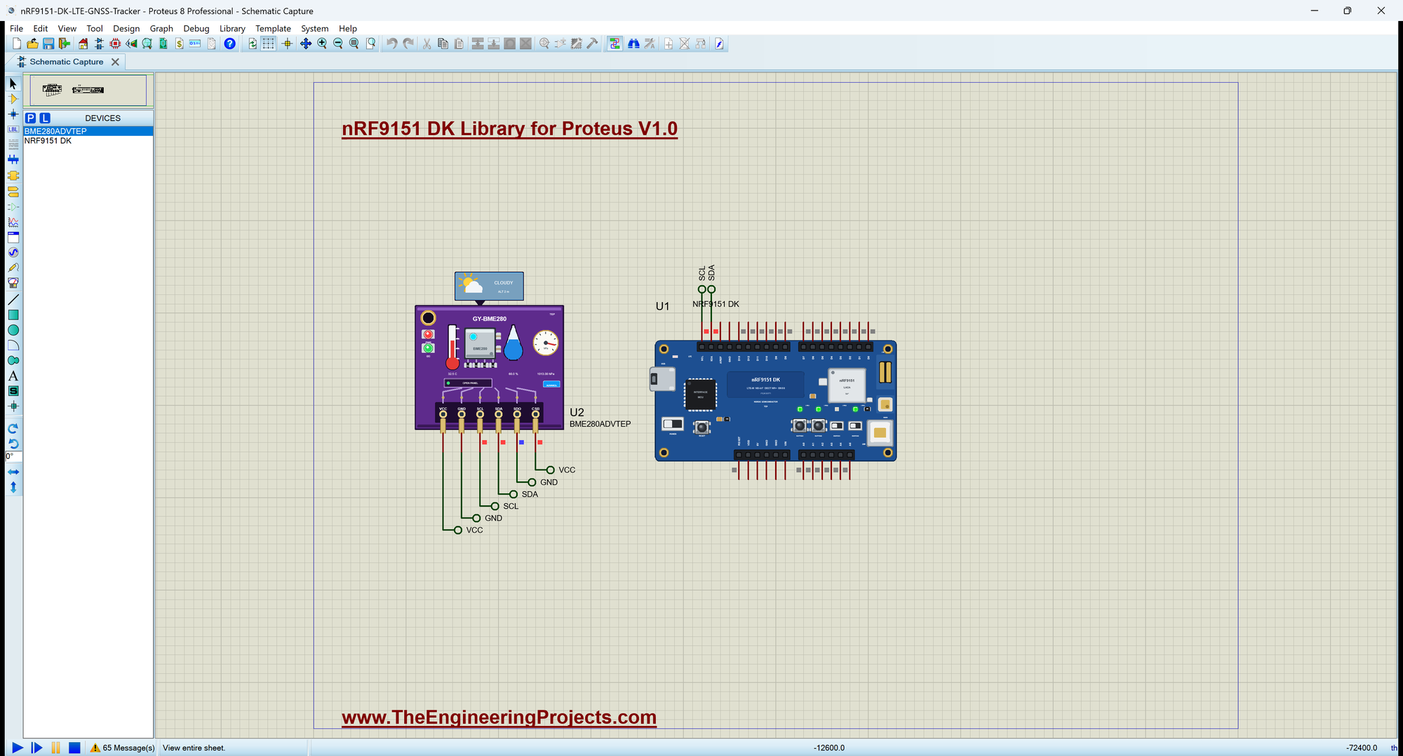
Open nRF9151-DK-LTE-GNSS-Tracker.pdsprj. U1 runs DK_LTE_GNSS_Tracker.hex, and U2 comes from our BME280 Sensor Library in the Advance version, on the I2C header, starting at 5 C. The owner's phone is the board's own Phone window, so the SMS need no wires. The serial monitor is the same window as our TEP Serial Monitor Advance for Proteus.
The Wiring
The BME280's SDA and SCL go to the DK's SDA and SCL pins. SDO goes to GND for the address 0x76, and CSB to VCC to select I2C. Everything else, the network, the SMS and the satellites, is wireless and lives inside the nRF9151.
Starting the Modem
startModem() switches the modem on, waits until it answers AT, and then sets it up with four commands: echo off, SMS as plain text, new SMS straight to the AT interface, and GNSS on:
void startModem() {
  pinMode(MODEM_ON, OUTPUT);
  digitalWrite(MODEM_ON, HIGH);                             // the modem starts (on the real chip: nrf_modem_lib_init())
  SerialModem.begin(115200);
  Serial.println(F("Starting the nRF9151 modem"));
  while (!sendAT("AT", 1000)) { }                           // it answers once it has started
  sendAT("ATE0", 500);
  sendAT("AT+CMGF=1", 500);                                 // SMS as text
  sendAT("AT+CNMI=2,2,0,0,0", 500);                         // a new SMS comes straight to the AT interface
  sendAT("AT+CGPS=1,1", 500);                               // GNSS on
  Serial.println(F("Modem ready: SMS and GNSS on, waiting for the network"));
}
Sending an SMS
An SMS is sent in two steps. AT+CMGS with the number makes the modem answer with a > prompt, then the text follows, ended by Ctrl+Z (character 26). LED3 lights for a moment so you can see each message leave:
void sendSms(const String &to, const String &text) {
  led(2, true); flashUntil = millis() + FLASH_MS;           // LED3: an SMS is going out
  SerialModem.print(F("AT+CMGS=\""));
  SerialModem.print(to);
  SerialModem.println(F("\""));
  unsigned long end = millis() + 2000;
  while (millis() < end && SerialModem.read() != '>') { }   // the modem's prompt
  SerialModem.print(text);
  SerialModem.write(26);                                    // Ctrl+Z ends the text
  Serial.print(F("SMS to ")); Serial.print(to); Serial.print(F(": ")); Serial.println(text);
  sentSms++;
  delay(200);
}
Listening to the Modem
Everything the modem says arrives through readModem(), which collects one line at a time and hands it to modemLine(). Three kinds of line matter: +CGPSINFO with the position, +CMT announcing an SMS (its text follows on the next line), and +CEREG with the registration state, where 1 means home network and 5 roaming:
void modemLine(const String &l) {
  if (smsNext) { smsNext = false; command(smsFrom, l); return; }
  if (l.startsWith("+CGPSINFO: ")) gpsLine(l.substring(11));
  else if (l.startsWith("+CMT:")) { smsFrom = between(l, '"'); smsNext = true; }
  else if (l.startsWith("+CEREG: ")) {                      // +CEREG: <n>,<stat>: 1 = home, 5 = roaming
    const int stat = field(l.substring(8), 1).toInt();
    const bool now = stat == 1 || stat == 5;
    if (now != registered) {
      registered = now;
      led(0, now);
      Serial.println(now ? F("LTE: registered on the network") : F("LTE: searching for the network"));
      if (now && fix && !told) { told = true; sendSms(owner, "Tracker online " + status()); }
    }
  }
}
The Commands
The owner controls the tracker with four words, the same four that the phone offers as quick keys:
void command(const String &from, String text) {
  text.trim(); text.toUpperCase();
  Serial.print(F("SMS from ")); Serial.print(from); Serial.print(F(": ")); Serial.println(text);
  if (text == "WHERE") sendSms(from, status());
  else if (text == "TRACK") { setTracking(true, F(">> SMS")); sendSms(from, "Tracking on: " + status()); }
  else if (text == "STOP") { setTracking(false, F(">> SMS")); sendSms(from, "Tracking off"); }
  else sendSms(from, "Commands: WHERE TRACK STOP HELP");
}
Where Am I?
Every two seconds the sketch asks for AT+CGPSINFO. The answer gives latitude and longitude in degrees and minutes, which toDegrees6() turns into millionths of a degree. A long integer keeps every digit, where a float would lose the last metres. mapLink() then builds a link that opens in any map app.
String mapLink() {
  return "https://maps.google.com/?q=" + degrees6(lat6) + "," + degrees6(lon6);
}
Keeping the Load Cold
Once a second checkTemp() reads the BME280. It sends an SMS only when the state changes, once when the load gets warmer than 8 C and once when it is cold again, so a long warm spell does not flood the owner with messages:
void checkTemp() {                                          // the load's temperature, and the WARM alarm
  tempC = bme.readTemperature();
  const bool now = tempC > WARM_C;
  if (now == warm) return;
  warm = now;
  Serial.print(now ? F(">> WARM: ") : F(">> Cold again: ")); Serial.print(tempC, 1); Serial.println(F(" C"));
  if (registered) sendSms(owner, String(now ? "WARM ALARM " : "Cold again ") + status());
}
Run the Simulation
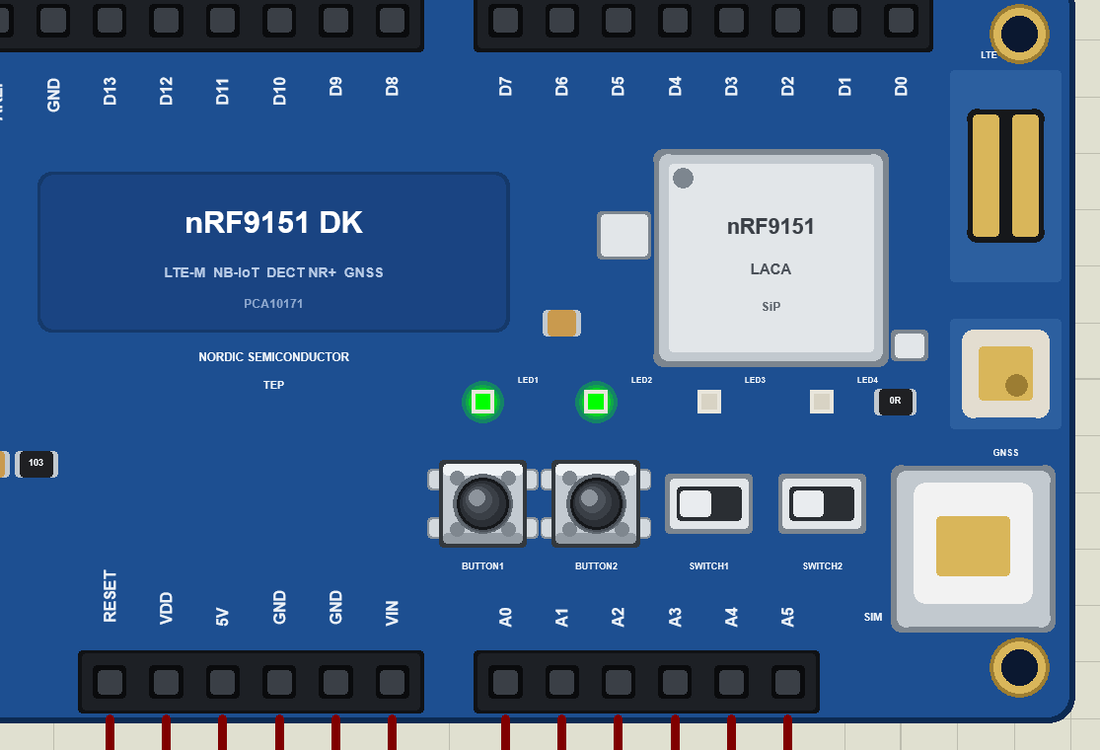
Press Run. The modem starts, answers, and begins to search for a network, with the LTE LED blinking. The Phone window's GNSS scene starts at PARKED, so the first AT+CGPSINFO answers already bring a position and LED2 lights. A few seconds later the modem registers, LED1 lights, and the tracker tells its owner that it is online, with a map link and the load's temperature:
nRF9151 DK LTE-M GNSS Cold-Chain Tracker - The Engineering Projects
Starting the nRF9151 modem
Modem ready: SMS and GNSS on, waiting for the network
SMS: WHERE, TRACK, STOP, HELP   BUTTON1 = send the position, BUTTON2 = tracking on / off
GNSS fix: 31.520400, 74.358700
LTE: registered on the network
SMS to +15555550191: Tracker online https://maps.google.com/?q=31.520400,74.358700 0 km/h, 5.0 C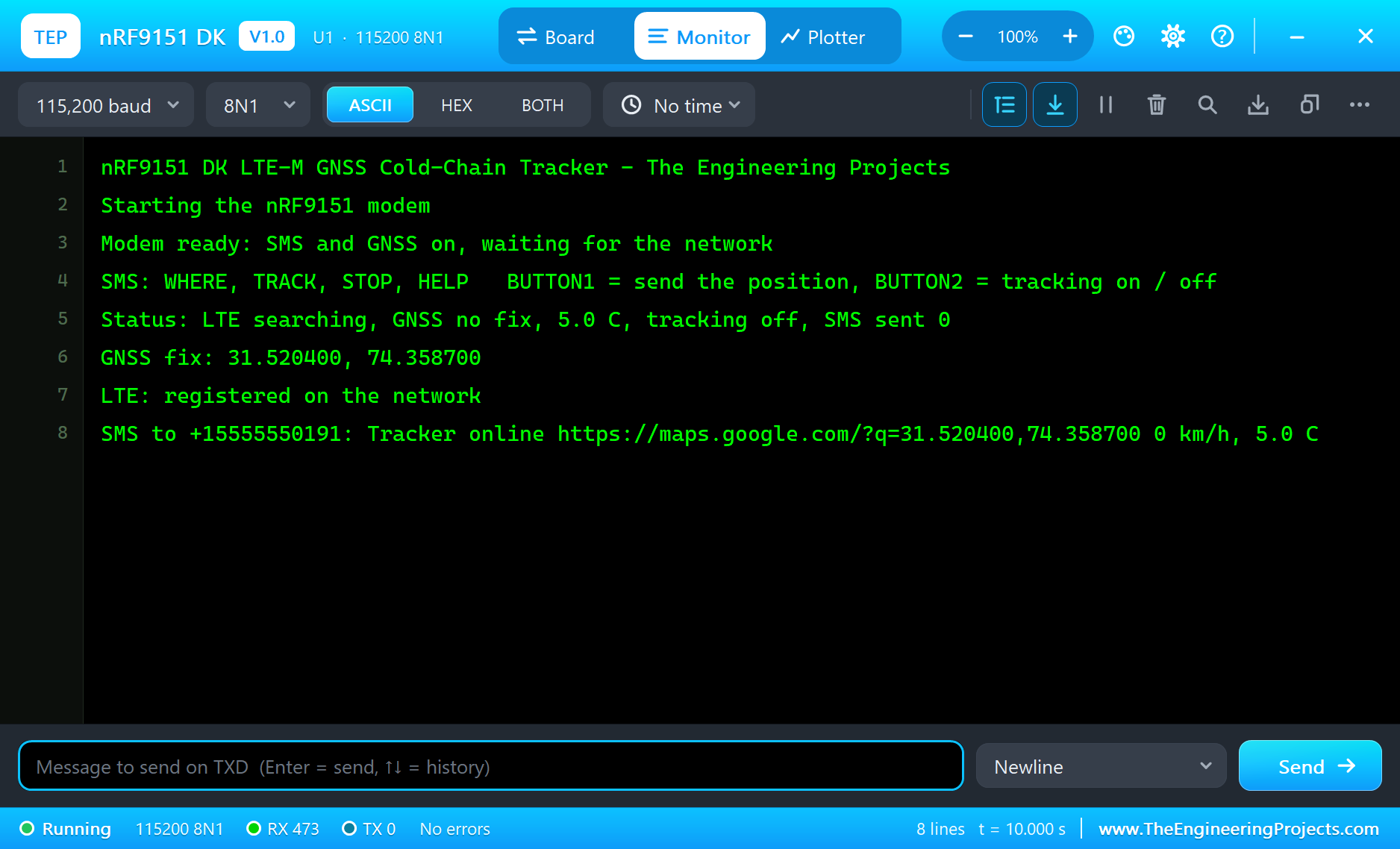
The Owner's Phone
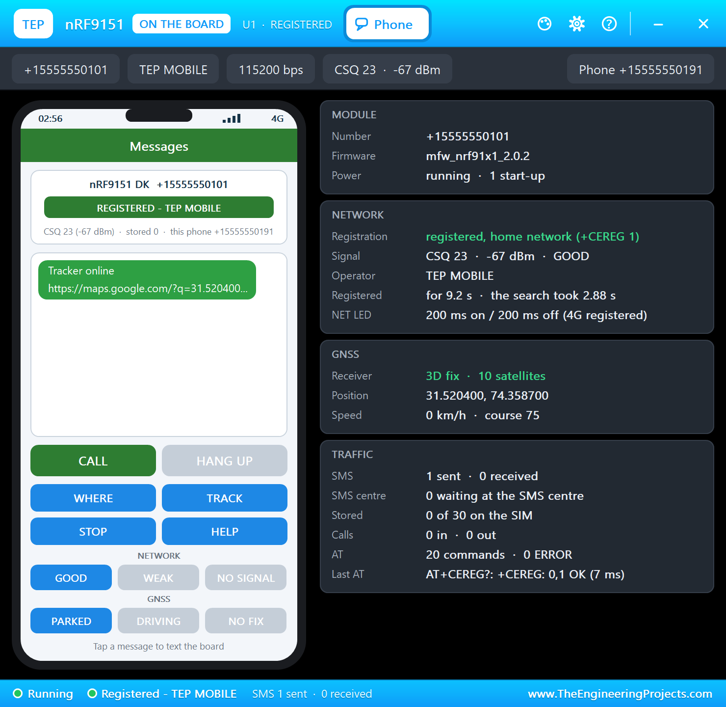
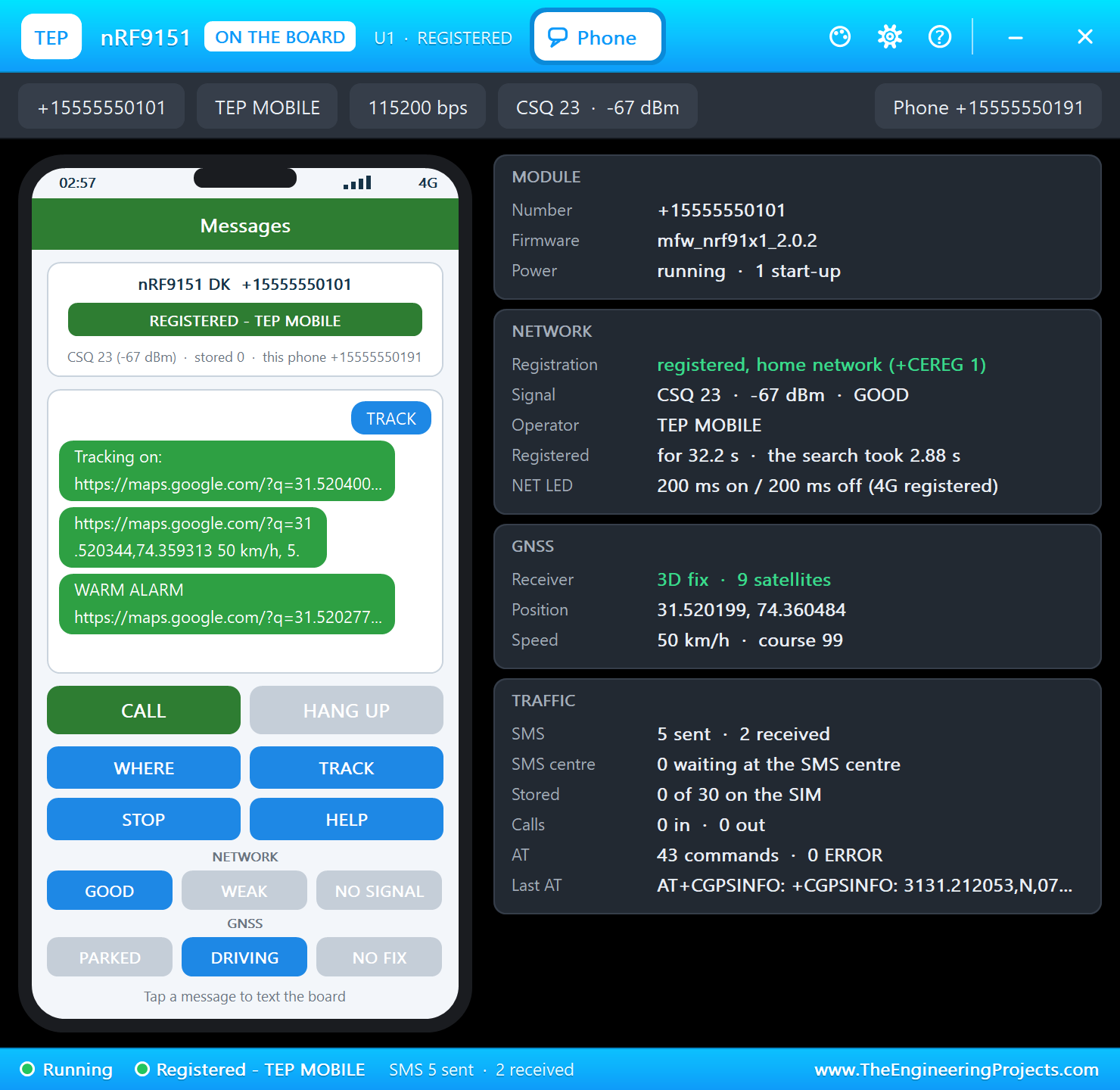
The board's Phone window opens at Run (a click on the SiP opens it again). Its left half is the owner's phone, with the messages, four quick keys and the network and GNSS scenes; its right half shows the modem itself: registration, signal, GNSS and the SMS traffic. The first message is already there:
Ask Where It Is
Press WHERE in the Phone window. The SMS reaches the board, the sketch reads it, and the answer comes back at once:
SMS from +15555550191: WHERE
SMS to +15555550191: https://maps.google.com/?q=31.520400,74.358700 0 km/h, 5.0 C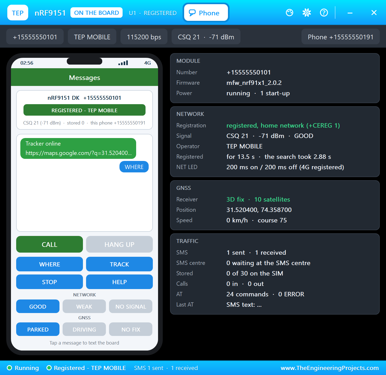
Track It While It Moves
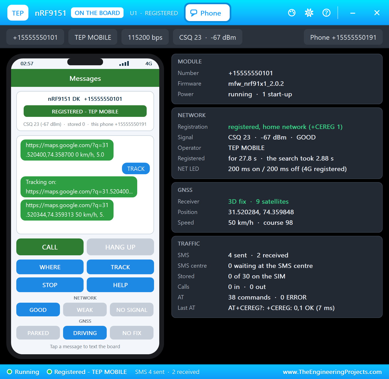
Press TRACK: LED4 lights, and a position will follow every 30 seconds. Set the scene to DRIVING and the position starts to move; BUTTON1 on the board sends the current one at once:
A Warm Load
Now open the BME280's pop-up and click further along the Temperature track, as if the truck's cooling had failed. Within a second the tracker sends the WARM alarm with the position and the temperature:
>> WARM: 32.5 C
SMS to +15555550191: WARM ALARM https://maps.google.com/?q=31.520277,74.359893 50 km/h, 32.5 C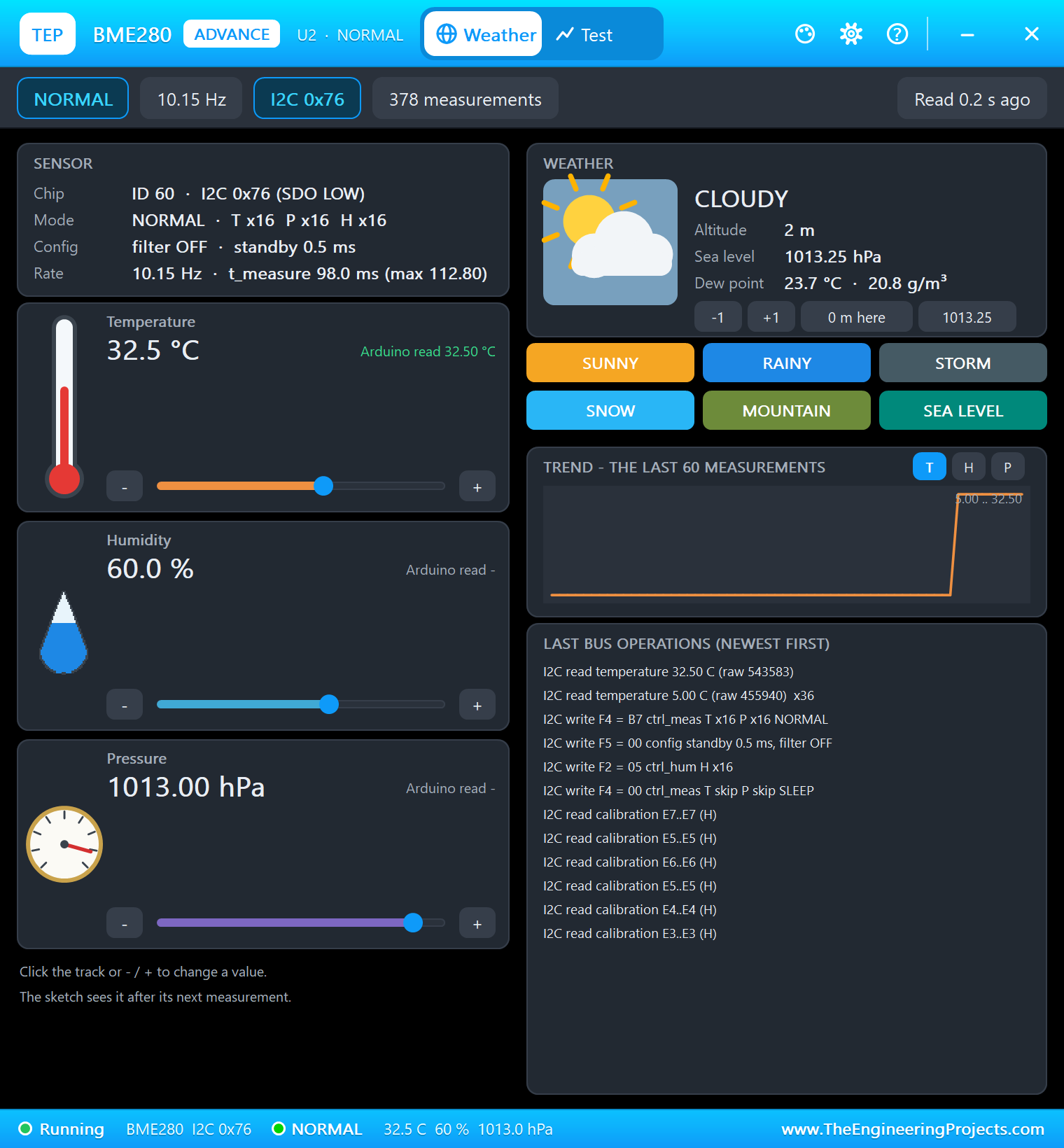
Here is the complete circuit while the simulation runs:
Stop and Lose the Sky
BUTTON2 turns tracking off and LED4 goes out. Set the scene to NO FIX, as in a tunnel or a parking garage, and LED2 goes out too, while LED1 stays on, because the network is still there:
>> BUTTON2
   BUTTON2: tracking OFF
GNSS: no fix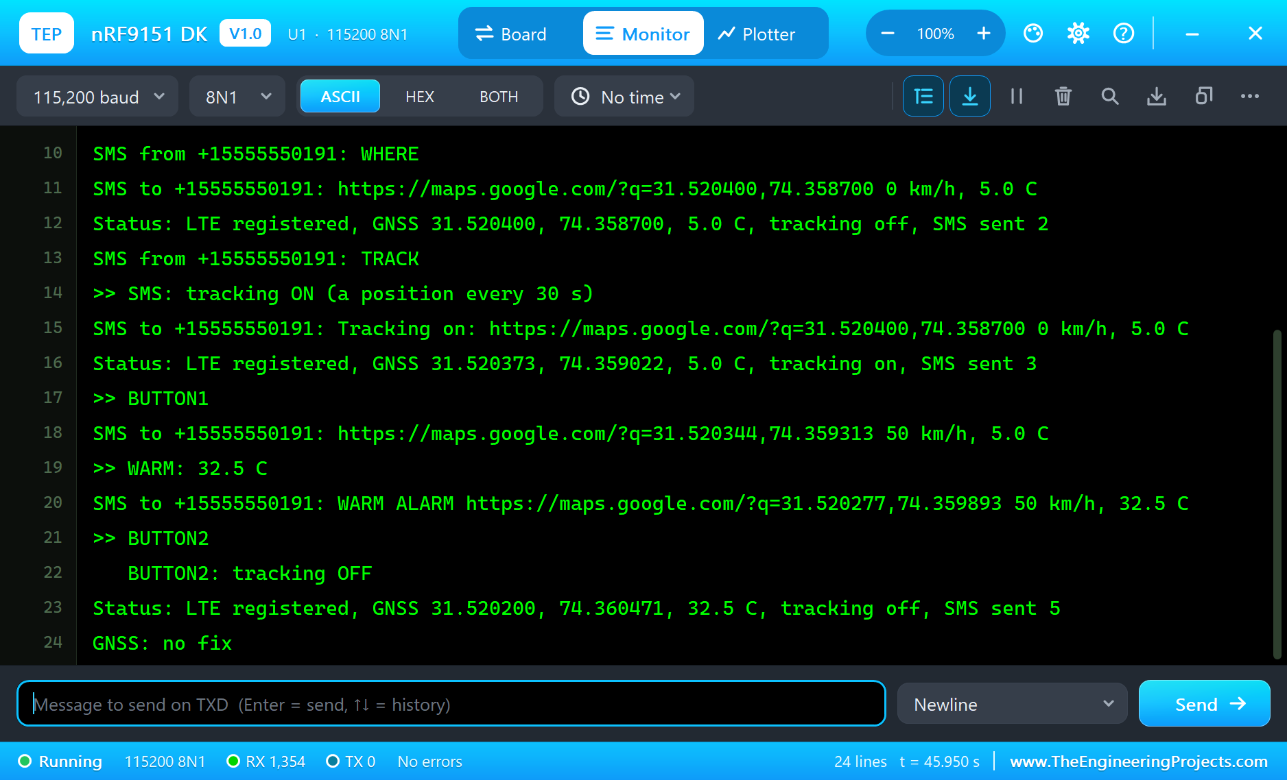
Try It Yourself
- Change
TRACK_MSto 10000 and count how many SMS a day that would be. - Add a SPEED command that answers with the speed only.
- Send an SMS only when the position has moved more than 100 m since the last one.
- Make LED2 blink while the tracker waits for its first fix.
Ideas to Extend the Tracker
- Add a humidity alarm for goods that must stay dry, with the BME280 that is already there.
- Watch an MPU6050 for a bump and send an alarm while parked.
- Keep the last 20 positions in an array and send them as one message.
- Use BUTTON2 as an SOS button that sends the position to two numbers.
Your Own Sketches
Write the sketch in the Arduino IDE with the board Nordic nRF9151 DK (TEP Proteus), use Sketch > Export Compiled Binary and set the part's PROGRAM property to the .hex. Talk to the modem with standard AT commands on SerialModem. On a real board, Nordic's nRF Connect SDK provides the modem library, an SMS library and a GNSS interface, and most real designs send their data to a server over LTE-M rather than by SMS; the structure of your program, waiting for registration and reacting to messages, stays the same.
Things to Know Before Using a Real nRF9151 DK
- A SIM and a plan: the network must support LTE-M or NB-IoT where you are; the kit's trial SIMs help at the start.
- GNSS needs the sky: the patch antenna wants a clear view upwards, and the first fix can take a minute or more.
- LTE and GNSS share time: the modem pauses GNSS while it transmits, so plan your reports around fixes.
- Power saving is half the design: PSM and eDRX decide the battery life, so test them early.
- Real SMS: the real modem sends SMS in PDU mode through Nordic's SMS library; text mode is a simplification here.
Properties of the nRF9151 DK
| Property | What it does |
|---|---|
| PROGRAM | the sketch: a .hex from TEP Boards for Proteus (board "Nordic nRF9151 DK") |
| MONITOR, BAUD, AUTOOPEN | the built-in serial monitor: on, its baud rate (115200), open at Run |
Troubleshooting
- The modem never answers: set
MODEM_ONHIGH and callSerialModem.begin(115200)first; sendATuntil it answers OK. - No SMS arrives:
AT+CMGF=1andAT+CNMI=2,2,0,0,0make a new SMS come straight to the sketch. - "No GNSS fix yet": turn GNSS on with
AT+CGPS=1,1and set the phone's scene to PARKED or DRIVING. - The LEDs look inverted: on this DK they light when the pin is HIGH.
- A number goes wrong above 32767: int is 16 bits in the simulation - use long.
Limitations of the Simulation
- There is no Bluetooth on the nRF9151. Data connections (IP, MQTT, CoAP), voice, DECT NR+, PSM and eDRX are not modelled; SMS is text mode only.
- The radio, its coverage and the SIM are not simulated, and the two slide switches are drawn only.
- Your sketch gets 8 KB of RAM in the simulation, and int is 16 bits there.
- nRF9151 and Nordic Semiconductor are names of Nordic Semiconductor ASA and Arduino of Arduino; this library is not made or endorsed by them or by Labcenter.
- Tested in Proteus 8.5 in November 2026 (the demo as shipped, about 46 s of simulation). Proteus 7 is not supported.
So, that was all about the nRF9151 DK Library for Proteus. I hope it helps you try your cellular IoT ideas in a simulation before you buy a board and a SIM - the modem, the SMS, the GNSS and your own logic, all on one sheet. If you have any questions, ask in the comments and I will help you out. Till the next tutorial, take care and have fun!

Comments
0