


IoT Car Dashboard with ESP32 - Proteus Simulation


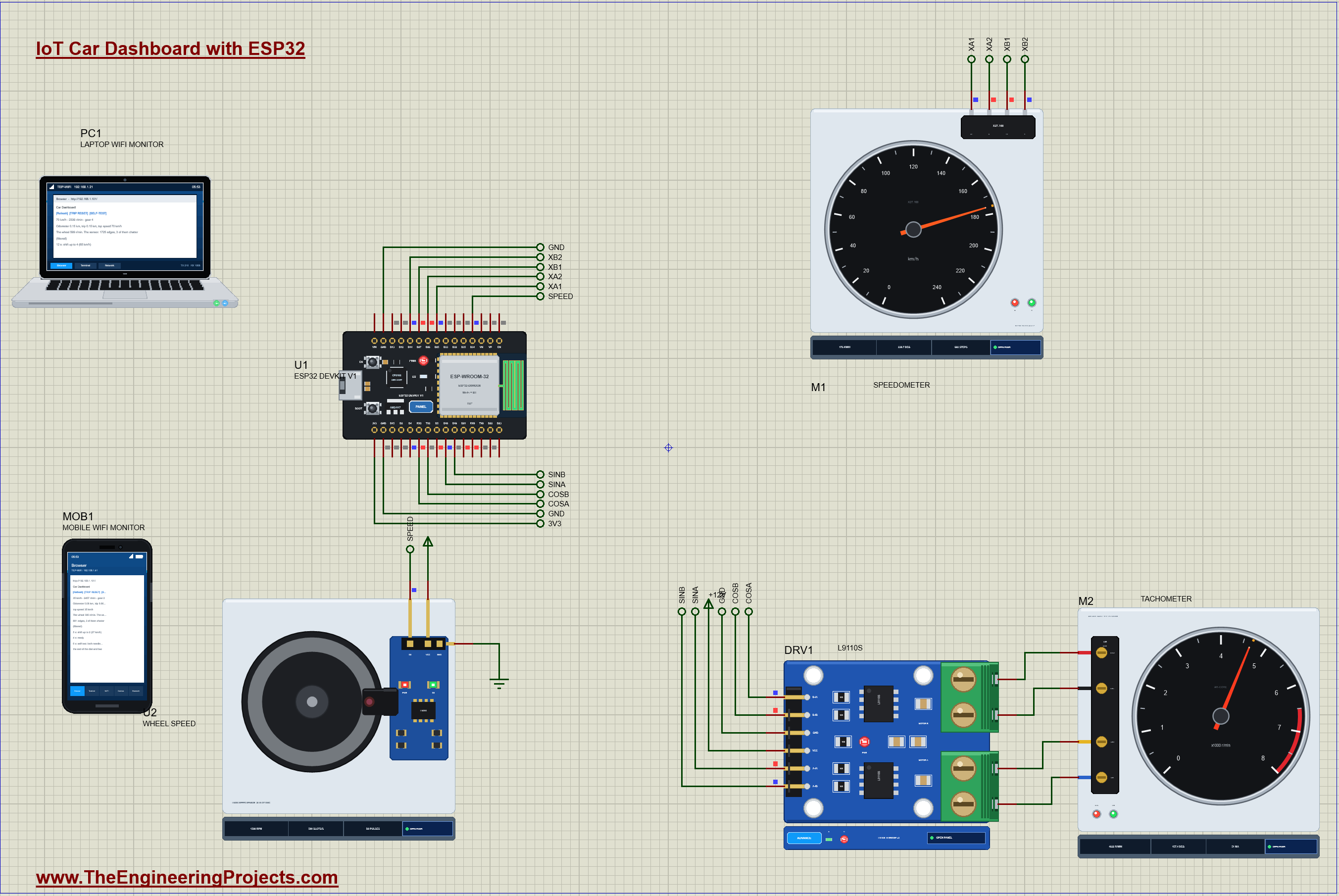
Hello friends, I hope you all are doing great. Today, I am going to share the IoT Car Dashboard with ESP32 - Proteus Simulation, the twenty-ninth project of our IoT Projects series. If you have searched for a Proteus simulation of an ESP32 speedometer with real gauge needles, here is a complete one. An ESP32 DevKit V1 is the brain of a car's instrument cluster: it measures the wheel's speed with an LM393 slotted optical sensor, drives an X27.168 stepper speedometer straight from four pins, works out the engine's speed through a five-speed automatic gearbox and shows it on an air-core tachometer, counts the odometer and the trip, warns of overspeed, and serves a live web dashboard to a laptop and a phone.
Most cars still show their speed with needles, and two clever little motors move them: a gauge stepper, which moves in tiny steps, and the older air-core movement, a magnet that simply points where two crossed coils tell it. In this tutorial, we will go through the circuit, learn how a slotted optical sensor turns a spinning disc into pulses and why its comparator chatters at low speed, measure the speed from the time between slots, step the X27.168 through its six states, steer the air-core needle with sine and cosine PWM through an L9110S, build the gearbox, walk through the Arduino sketch, and then run the simulation: the cluster's self-test, a drive from 35 to 175 km/h and back down to a crawl, an overspeed warning, the chatter filter at work, the trip reset and a self-test from the dashboard. At the end, you can download the project with the sketch and every library file.
NOTICE: Our team has put a lot of effort into this project: the circuit, the code and every part in the simulation are our own work, and you get them all free. Your feedback is the fuel that keeps us going, so please tell us what you think in the comments below. And if our free projects help you, you can buy us a coffee. So, let's get started with the IoT Car Dashboard with ESP32 - Proteus Simulation:
What Does This Car Dashboard Do?
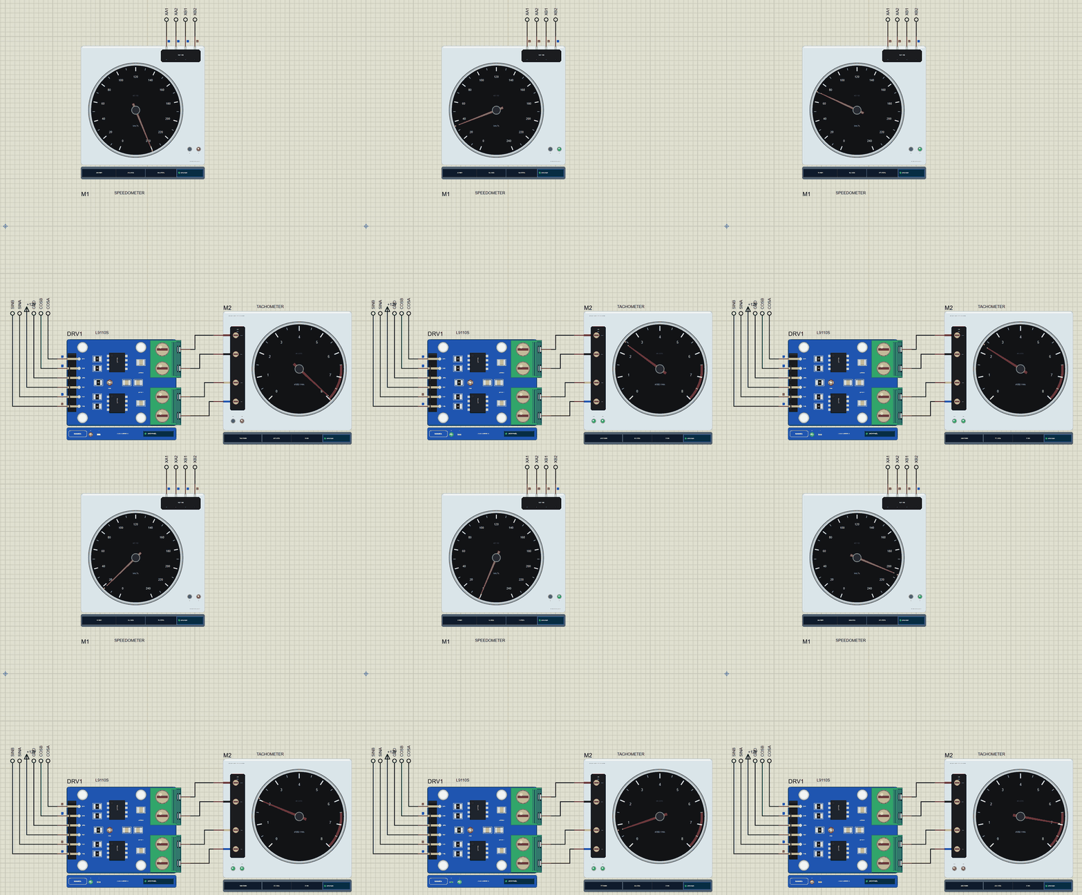
- Measures the speed: an LM393 slotted sensor on a 20-slot disc on the wheel, 20 pulses a turn, a 1.95 m tyre.
- A real speedometer needle: an X27.168 gauge stepper, 0 to 240 km/h in 945 steps of a third of a degree.
- A real tachometer needle: an air-core gauge, 0 to 8,000 r/min over 270 degrees, through an L9110S on 12 V.
- A five-speed automatic: up a gear above 3,000 r/min, down below 1,500, the engine never under its 800 r/min idle.
- Odometer, trip and top speed: counted from the slots, 9.75 cm a slot.
- Overspeed warning: above 120 km/h, on the dashboard and in the events.
- The cluster's self-test: both needles to the end of the dial and back at power-up, and from the dashboard.
It is a fun project for anyone who likes cars and a good lesson in interrupts, stepper sequences, PWM and a little trigonometry. In the simulation, the wheel's speed comes from the LM393's pop-up: Stop, 30, 60, 150, 300, 600 or 1,500 r/min.
Components Used in the Proteus Simulation
All the parts come from our Proteus libraries, each with its own tutorial. The project zip at the end includes every LIB and DLL file.
| Part | Proteus device | Library post | Connection |
|---|---|---|---|
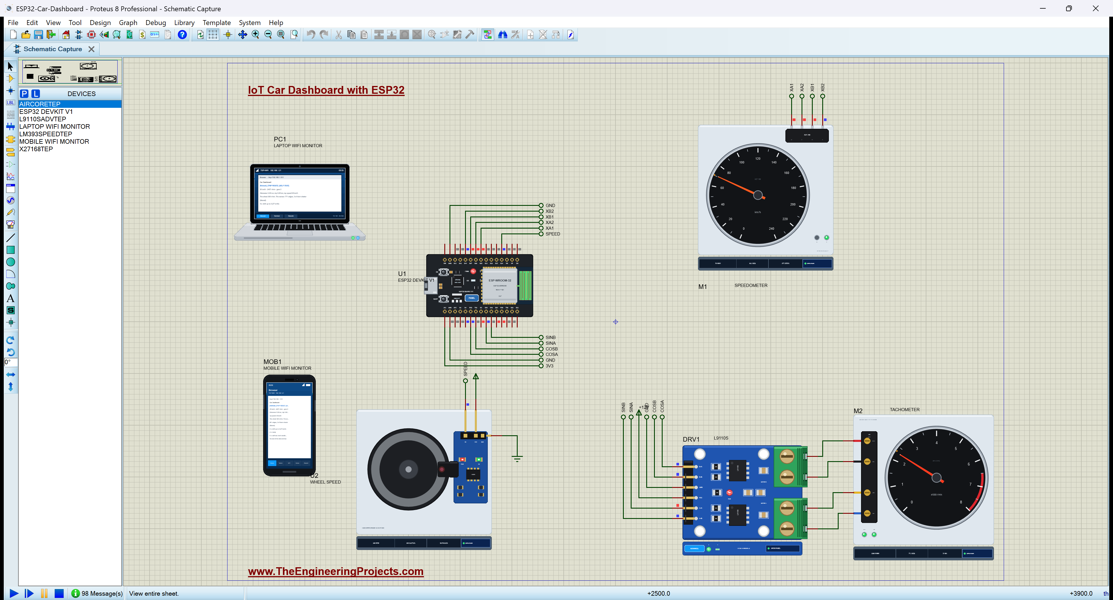
| ESP32 DevKit V1 | ESP32 DEVKIT V1 | ESP32 DevKit V1 Library for Proteus | U1, TEP-WiFi 192.168.1.101 |
| X27.168 speedometer (gauge stepper) | X27168TEP | X27.168 Speedometer Gauge Library | M1, D25 / D26 / D27 / D14 |
| Air-core tachometer | AIRCORETEP | Air-Core Gauge Library | M2, on the L9110S |
| L9110S dual H-bridge | L9110SADVTEP | L9110S Motor Driver Library | DRV1, GPIO16 / 17 / 18 / 19, 12 V |
| LM393 speed sensor, 20-slot disc | LM393SPEEDTEP | LM393 Speed Sensor Library | U2, D0 on D34 |
| Laptop WiFi Monitor | LAPTOP WIFI MONITOR | Laptop WiFi Monitor | PC1 |
| Mobile WiFi Monitor | MOBILE WIFI MONITOR | Mobile WiFi Monitor | MOB1 |
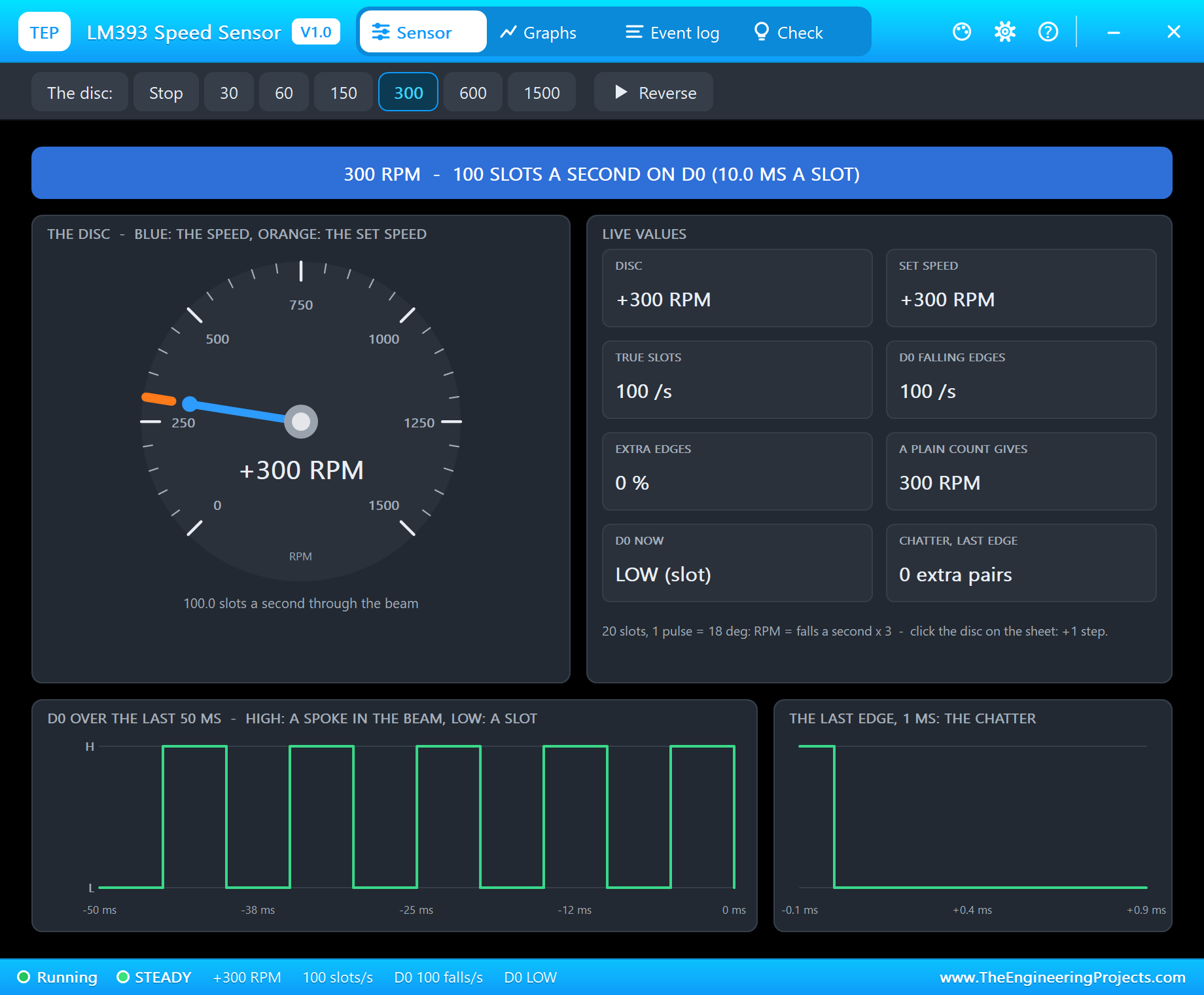
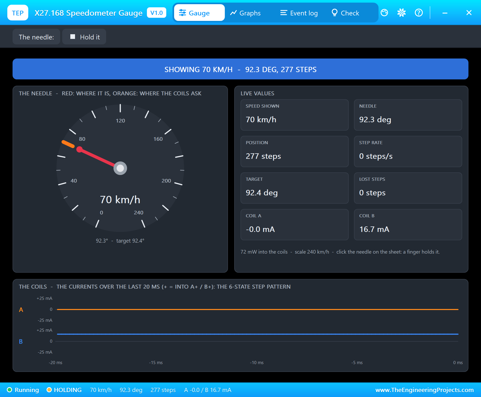
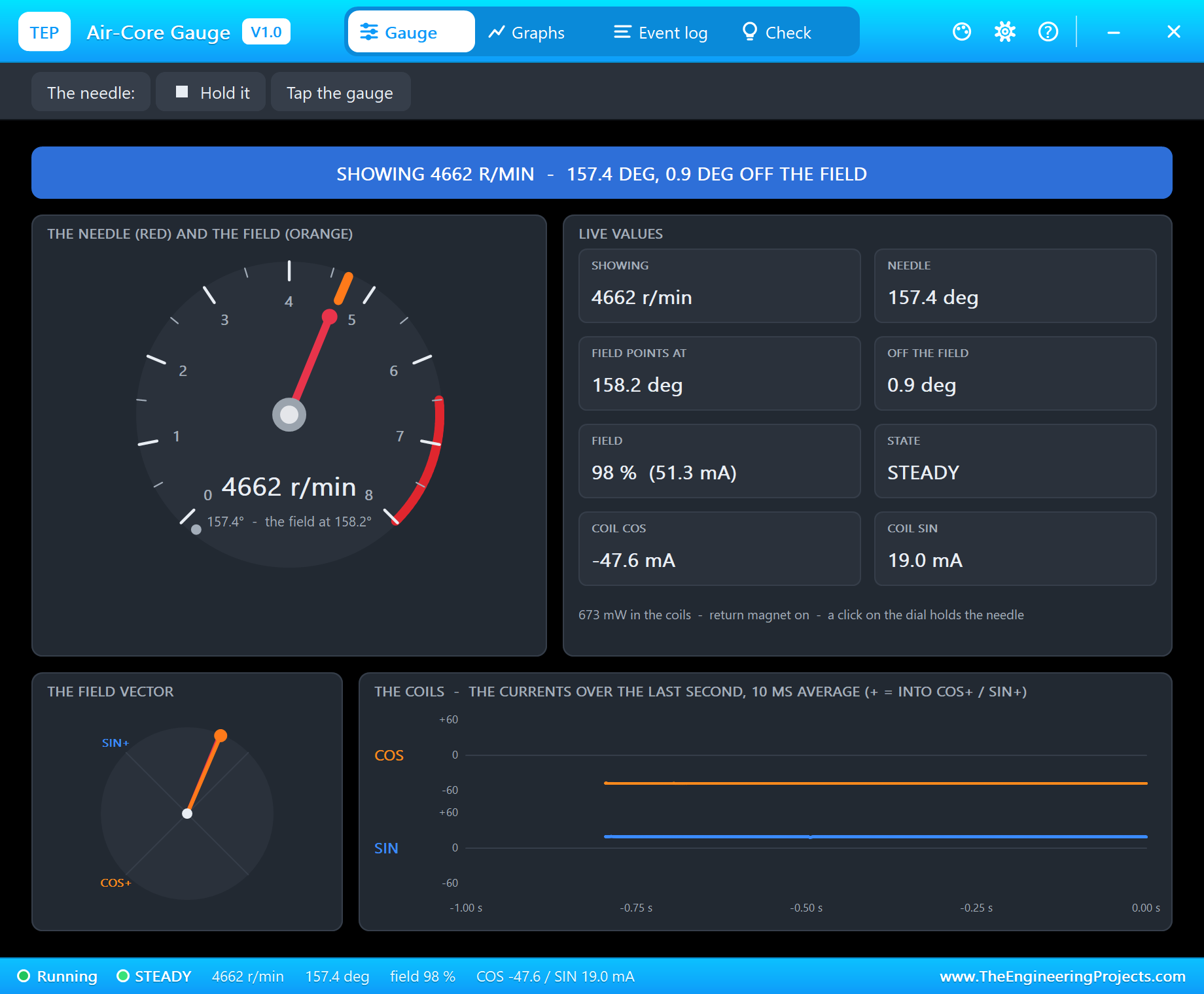
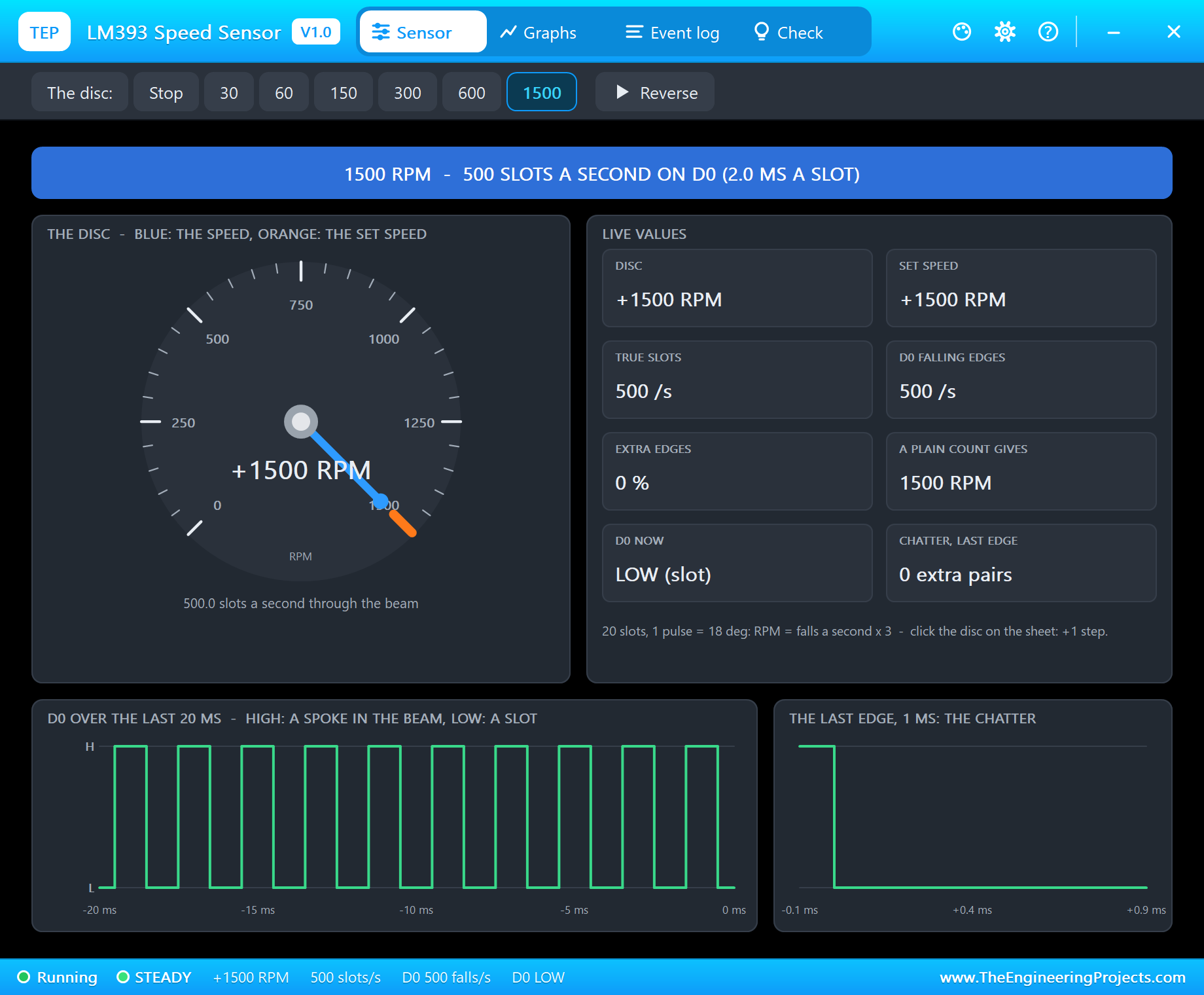
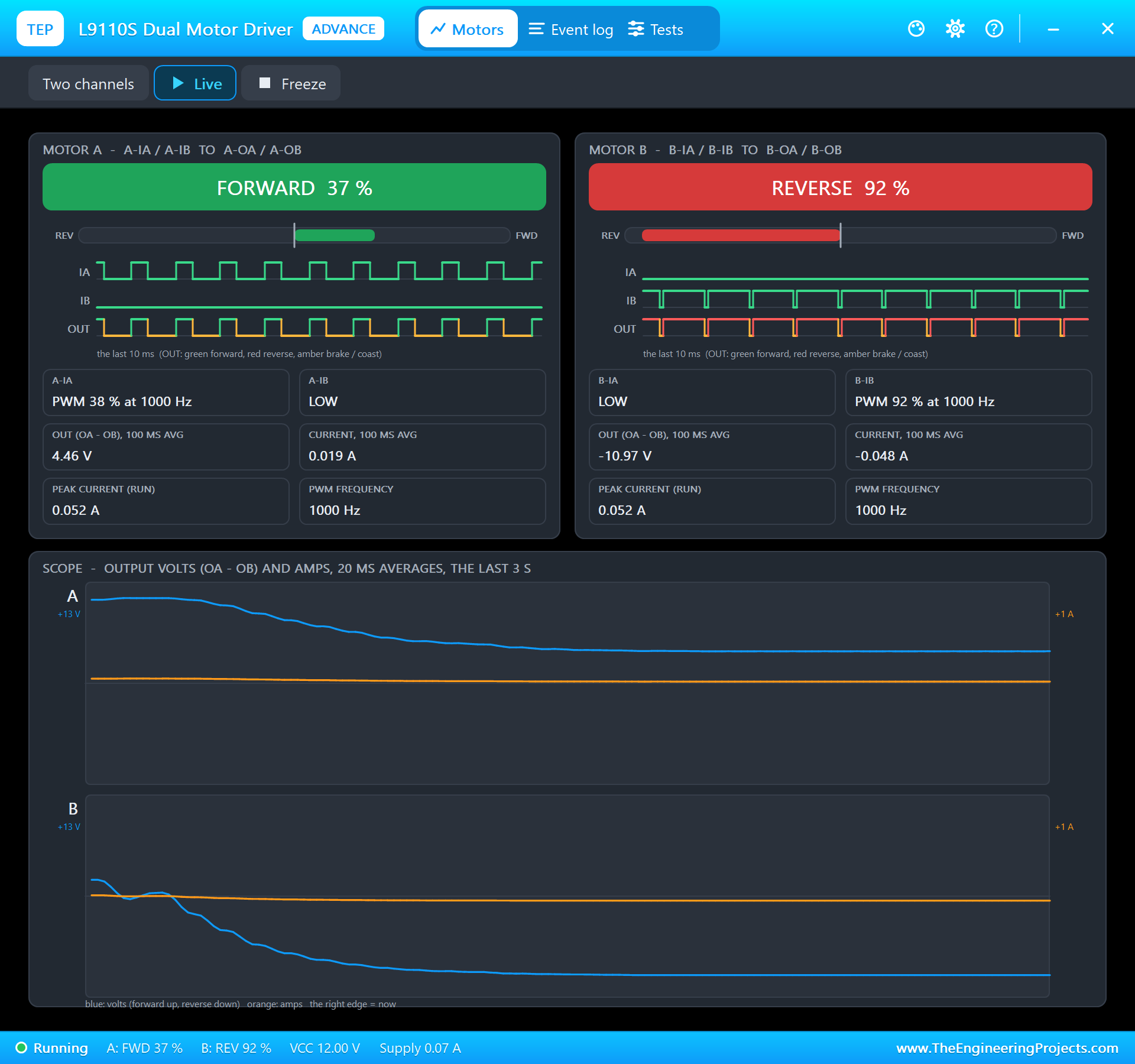
All four parts are models with pop-ups. The speedometer's pop-up shows the dial, the position in steps, the step rate, lost steps and the two coil currents. The tachometer's pop-up shows the needle, the field the coils make and the coil currents. The L9110S's pop-up shows both channels with their PWM and current. The LM393's pop-up sets the wheel's speed and shows the true slot rate, the edges on D0 and the extra edges of the chatter.
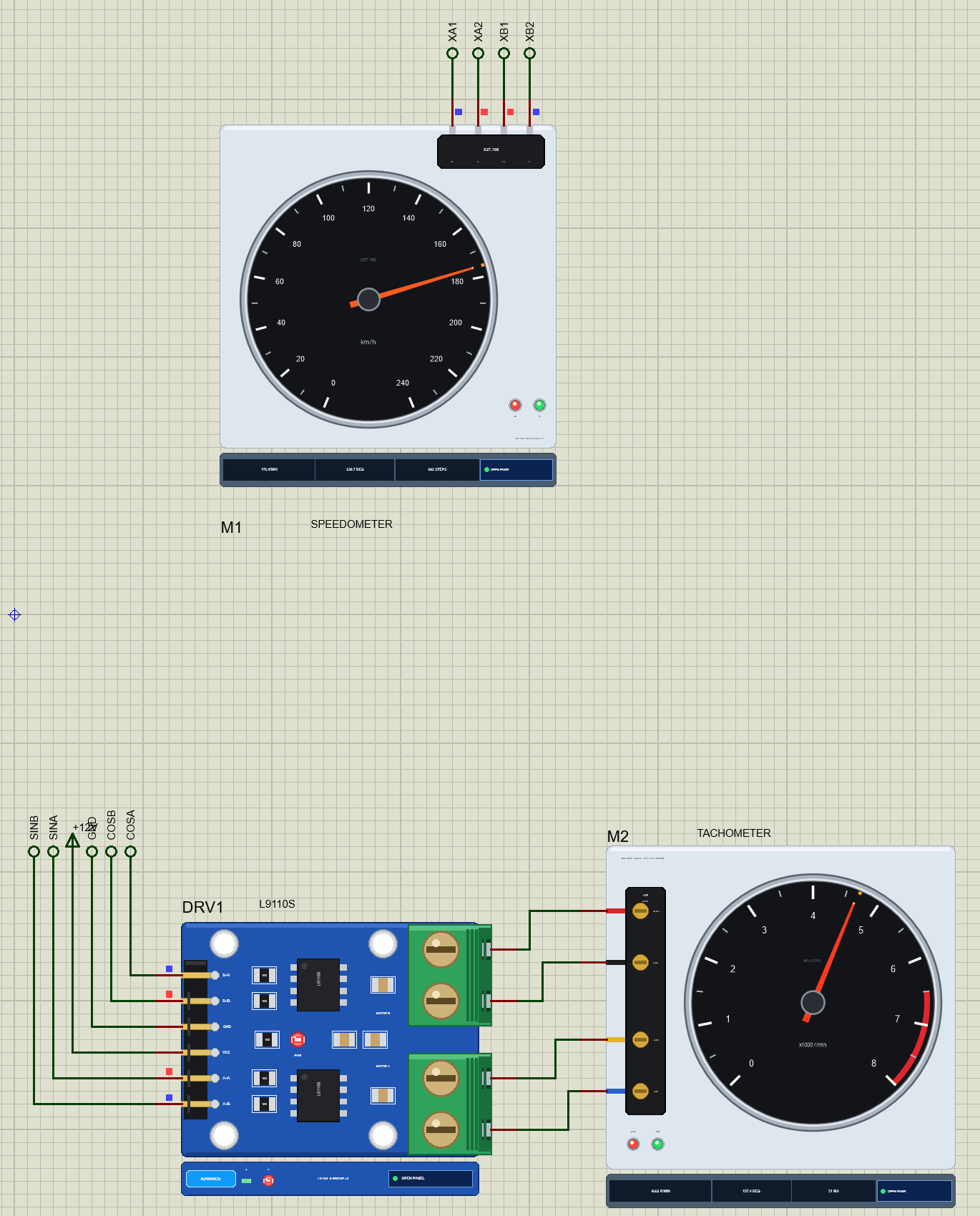
Proteus Simulation of the Car Dashboard: the Circuit
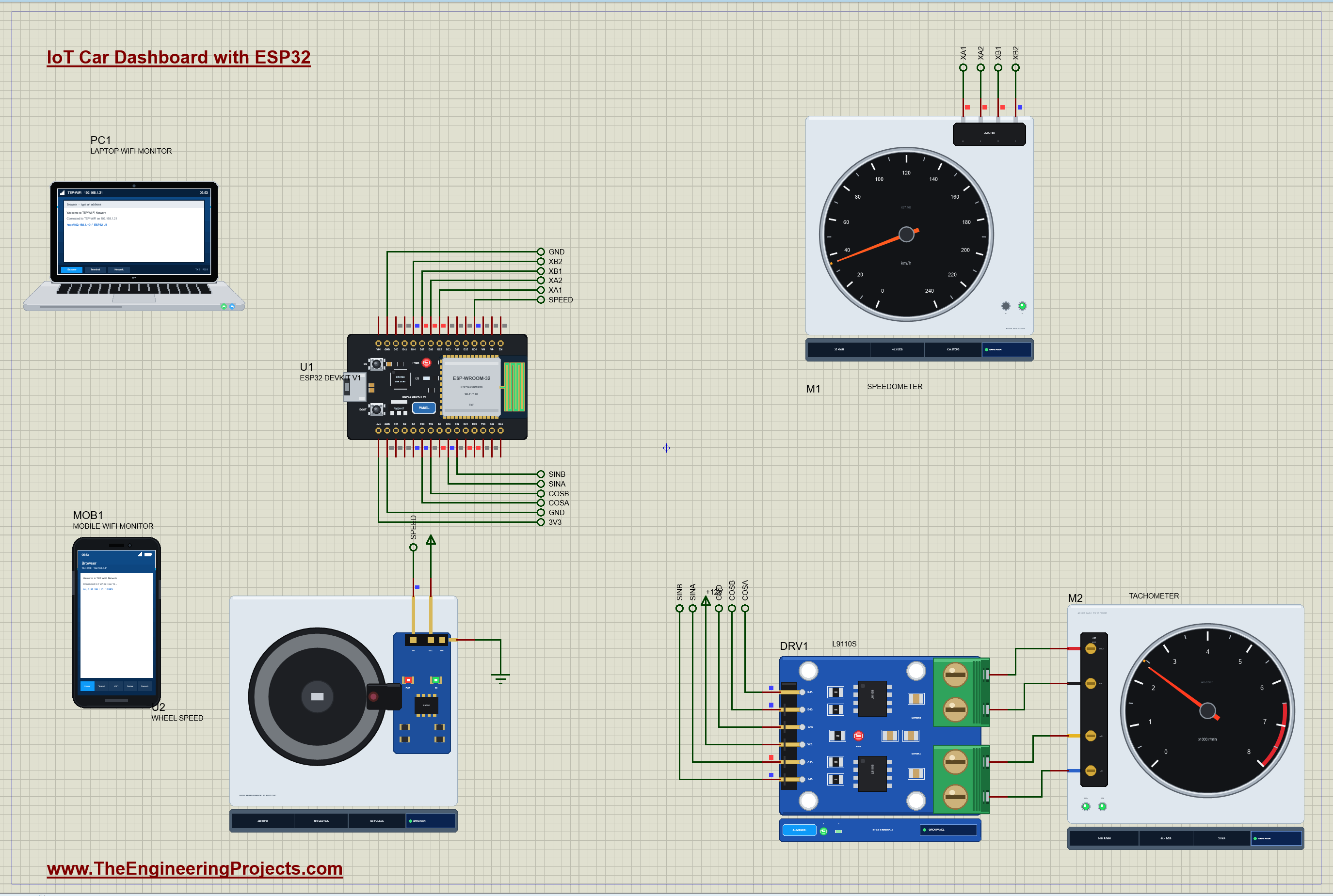
| Part | Pins | ESP32 DevKit V1 |
|---|---|---|
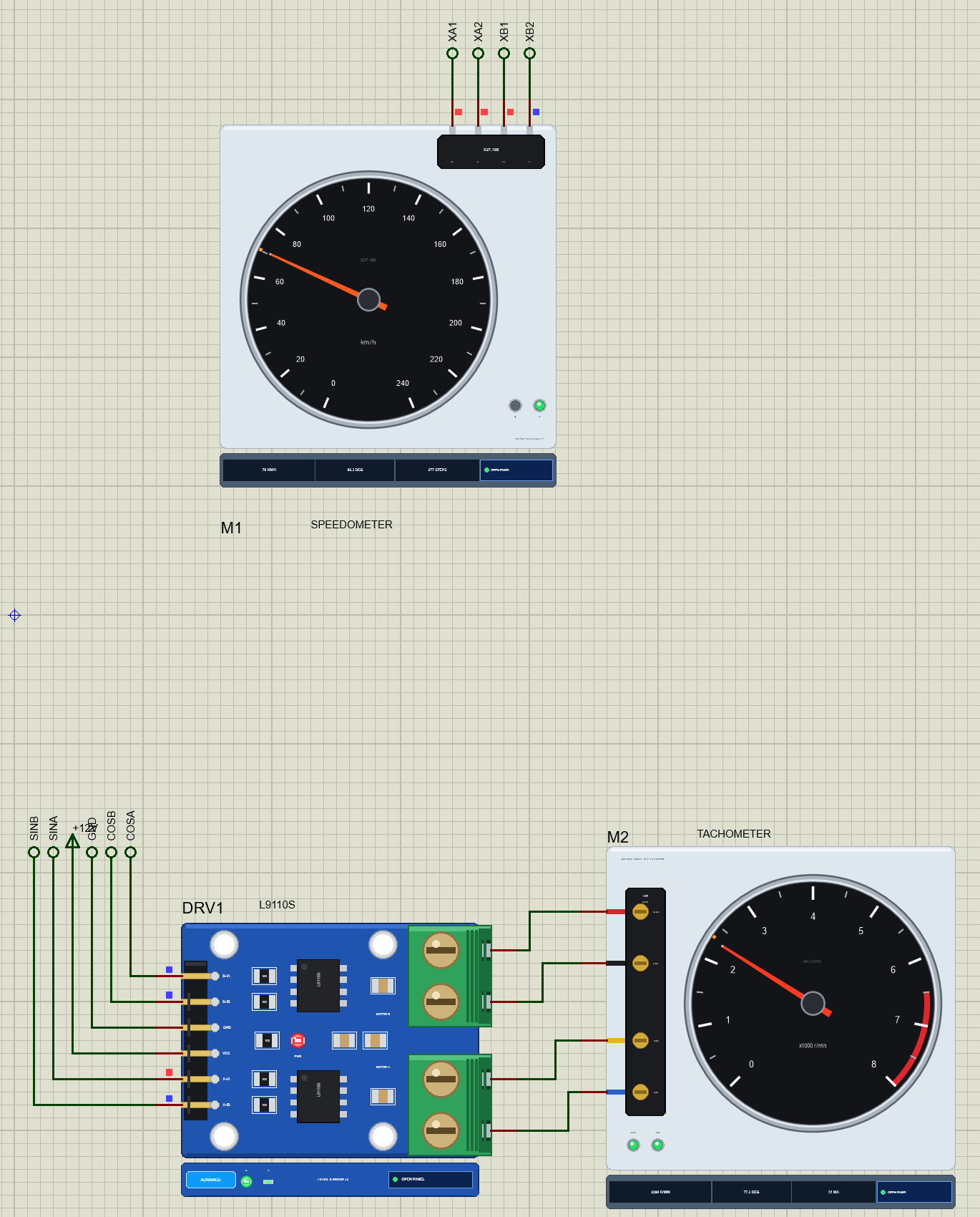
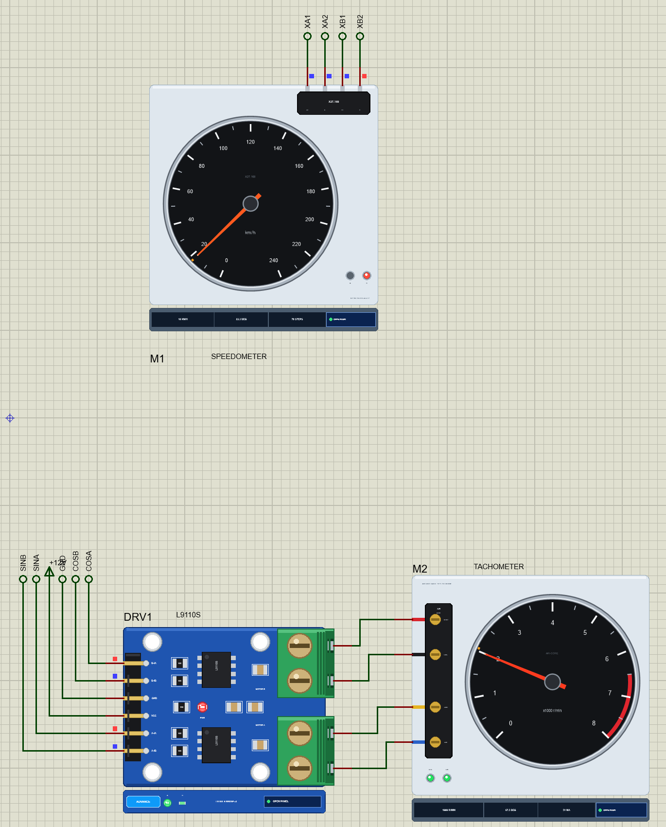
| M1 X27.168 speedometer | A+ / A- / B+ / B- | D25 / D26 / D27 / D14 |
| DRV1 L9110S inputs | B-IA / B-IB / A-IA / A-IB | RX2 (GPIO16) / TX2 (GPIO17) / D18 / D19 |
| DRV1 L9110S power | VCC / GND | +12V / GND |
| M2 air-core tachometer | COS+ / COS- / SIN+ / SIN- | B-OA / B-OB / A-OA / A-OB of the L9110S |
| U2 LM393 speed sensor | D0 / VCC / GND | D34 / the 5 V rail / GND |
The X27.168 is so small that its 260 ohm coils take about 13 mA at 3.3 V, within what a GPIO pin can give, so four pins drive it directly, with no driver. The air-core gauge has 12 V coils, so an L9110S switches them: motor B of the driver feeds the COS coil and motor A the SIN coil. The LM393 module's D0 output goes to D34, an input-only pin, which is all a sensor needs. In the simulation the LM393 model takes its power from the 5 V rail; on a real board, run it from 3.3 V so its output suits the ESP32.
How the Car Dashboard Works
Speed from a Slotted Disc
The LM393 module is a U-shaped slot with an infrared LED on one side and a phototransistor on the other. A disc with 20 slots turns in the gap: light through a slot pulls D0 low, a spoke between slots lets it go high. So one turn of the wheel gives 20 falling edges. The sketch catches them with an interrupt and, more usefully, times them: the wheel's r/min is 60,000,000 divided by the time between two slots in microseconds times 20. Worked example: slots 5,000 microseconds apart mean 60,000,000 / (5,000 x 20) = 600 r/min. With a tyre that rolls 1.95 m a turn, that is 600 x 1.95 x 60 / 1,000 = 70.2 km/h.
Why the Sensor Chatters
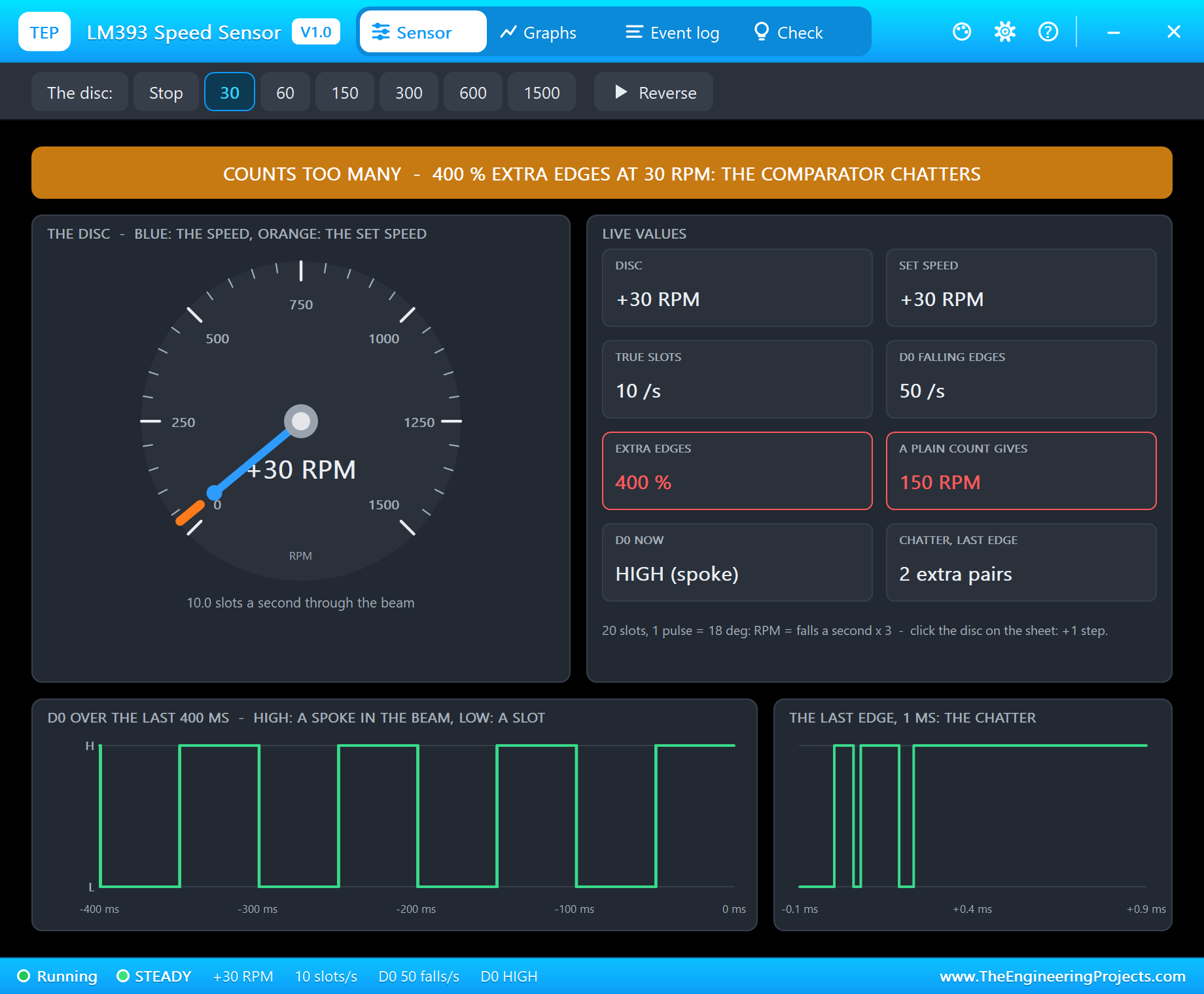
At low speed a slot's edge crosses the beam slowly, and the phototransistor's voltage creeps through the comparator's threshold. Noise near the threshold makes the comparator flip back and forth: one slot edge becomes a short burst of edges 15 to 50 microseconds apart. A plain count reads the speed far too high, at 30 r/min about five times too high. The cure took us three tries, and each one teaches something. A lockout of 300 microseconds after each slot failed at 30 r/min: the chatter at such a slow edge lasted longer, and the speed jumped to 472 km/h. A lockout of a quarter of the last period read exactly double, 60 r/min: the comparator chatters at both edges of a slot, also when the light leaves it, half a period after the real edge. Reading D0 inside the interrupt to tell the two apart failed too: the chatter pulses last 15 to 50 microseconds, and by the time the interrupt runs the level has often changed again. What works uses the physics of a burst: a burst of falls at the slot's leading edge ends with D0 low, the light now coming through the slot; a burst at its trailing edge ends high, a spoke now in the beam. So at low speed the sketch waits until a burst is over, 1 ms without a fall, then reads D0 once, when it is steady: low means a slot began, timed by the burst's first fall. Above 250 r/min there is no chatter, and every fall is simply a slot.
The X27.168 Gauge Stepper
The X27.168 is a tiny stepper motor with a 180:1 gearbox, made for car dashboards. Its two coils sit 60 degrees apart, and a six-state sequence on the four pins turns the needle a third of a degree a step: 945 steps for its whole 315-degree sweep. It has no sensor, so the sketch zeroes it at power-up by stepping 1,000 times downwards: the needle ends against its stop, whatever it showed before. Worked example: 70.2 km/h x 945 / 240 = 276 steps, 92 degrees. A ramp keeps it from losing steps: 3,000 microseconds a step at the start, down to 600 in the middle of a long move.
The Air-Core Gauge and the L9110S
An air-core gauge has no motor at all: two coils wound crossed at 90 degrees, and a magnet on the needle's shaft. The magnet turns to point along the two coils' combined field. Drive the COS coil with cos(angle) and the SIN coil with sin(angle), and the field, and so the needle, points at that angle. The L9110S does the driving: for each coil one input gets a PWM, 1,000 Hz in the simulation, and the other stays low; the sign of the cosine or sine picks which input. Worked example: 2,340 r/min on the 8,000 r/min, 270-degree dial is 79 degrees, so COS = cos 79 = 0.19, 19 percent PWM, and SIN = sin 79 = 0.98. The sketch turns the field at most 4 degrees every 10 ms: a jump of more than 180 degrees would send the magnet the short way round, onto its stop pin.
The Gearbox
| Gear | Ratio | Engine at 600 wheel r/min (70 km/h) |
|---|---|---|
| 1 | 3.50 | 8,190 r/min - too high, up |
| 2 | 2.10 | 4,914 r/min - too high, up |
| 3 | 1.40 | 3,276 r/min - still above 3,000, up |
| 4 | 1.00 | 2,340 r/min - between 1,500 and 3,000: stay |
| 5 | 0.80 | (used above 3,000 r/min in 4th) |
The engine's speed is the wheel's r/min times the gear's ratio times the final drive, 3.90, never less than the 800 r/min idle. The sketch shifts up above 3,000 r/min and down below 1,500, one gear at a time, so a quick change of speed gives a run of shifts, just as an automatic does.
The Arduino Code Explained
The whole sketch is included in the download. It needs no extra library: it drives the gauges and reads the sensor itself, and uses the ESP32's WiFi and WebServer libraries. At the top are the car's numbers:
const float WHEEL_M = 1.95;                  // m: the tyre's rolling circumference (a 195/65 R15)
const byte SLOTS = 20;                       // slots in the disc
const unsigned long BURST_US = 300;          // falls closer than this to the last one belong to the same burst (the chatter)
const unsigned long QUIET_US = 1000;         // a burst is over after 1 ms without a fall: then D0 tells which slot edge it was
const unsigned long FAST_US = 12000;         // slots closer than 12 ms (250 r/min and up): no chatter, every fall is a slot
const float MAX_WHEEL_RPM = 3000;            // more is a wrong reading, not a speed (350 km/h)
const float RATIO[5] = {3.50, 2.10, 1.40, 1.00, 0.80};
const float FINAL_DRIVE = 3.90;
The Slot Interrupt
if (now - lastFall < BURST_US) { glitches++; lastFall = now; return; } // within a burst: chatter if (digitalRead(SENSOR_PIN) == LOW) { noInterrupts(); slot(at); interrupts(); } // the light came in: a slot float rpm = (p == 0 || micros() - le > 1000000UL) ? 0 : 60e6 / ((float)p * SLOTS); // no slot for 1 s: stopped kmh = wheelRpm * WHEEL_M * 60 / 1000;The Speedometer
const byte STATE_MAP[6] = {0x9, 0x1, 0x7, 0x6, 0xE, 0x8}; // the X27's six states: bit 0 A+, 1 A-, 2 B+, 3 B- xNext = micros() + (unsigned long)max(600.0, 3000.0 / sqrt(1.0 + edge * 0.5)); for (int i = 0; i < X_STEPS + 55; i++) { xStep(-1); delayMicroseconds(800); }The Tachometer
void acDrive(float deg) { float r = deg * PI / 180; coil(cos(r), COS_A, COS_B); coil(sin(r), SIN_A, SIN_B); } if (v >= 0) { analogWrite(b, 0); analogWrite(a, d); } else { analogWrite(a, 0); analogWrite(b, d); }The Gearbox
if (e > UP_RPM && gear < 5) { gear++; snprintf(t, sizeof t, "shift up to %u (%d km/h)", gear, (int)kmh); event(t); } engine = max((float)IDLE_RPM, wheelRpm * RATIO[gear - 1] * FINAL_DRIVE);The pages are / (the dashboard), /trip (reset the trip), /test (the self-test sweep) and /data (JSON). The dashboard puts its three links first and stays short, because the WiFi Monitors show one screen of a page.
How to Run the Proteus Simulation
- Download the project zip below and install the library files (the steps are under the download button).
- Open ESP32-Car-Dashboard.pdsprj from the Proteus Simulation folder. Keep the HEX and the DLL files next to it.
- Press Play. Both needles sweep to the end and back; then the wheel turns at 300 r/min, 35 km/h in gear 2.
- In the LM393's pop-up (U2), pick the wheel's speed: 600, 1,500, 150, 30 r/min or Stop.
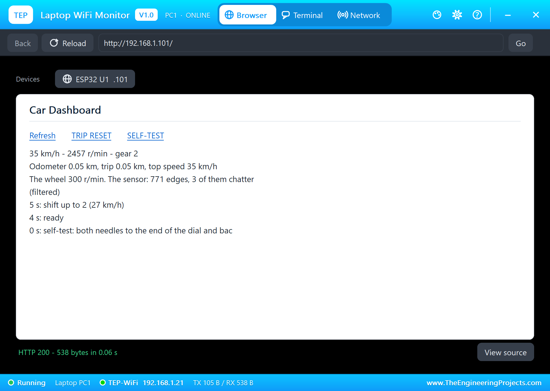
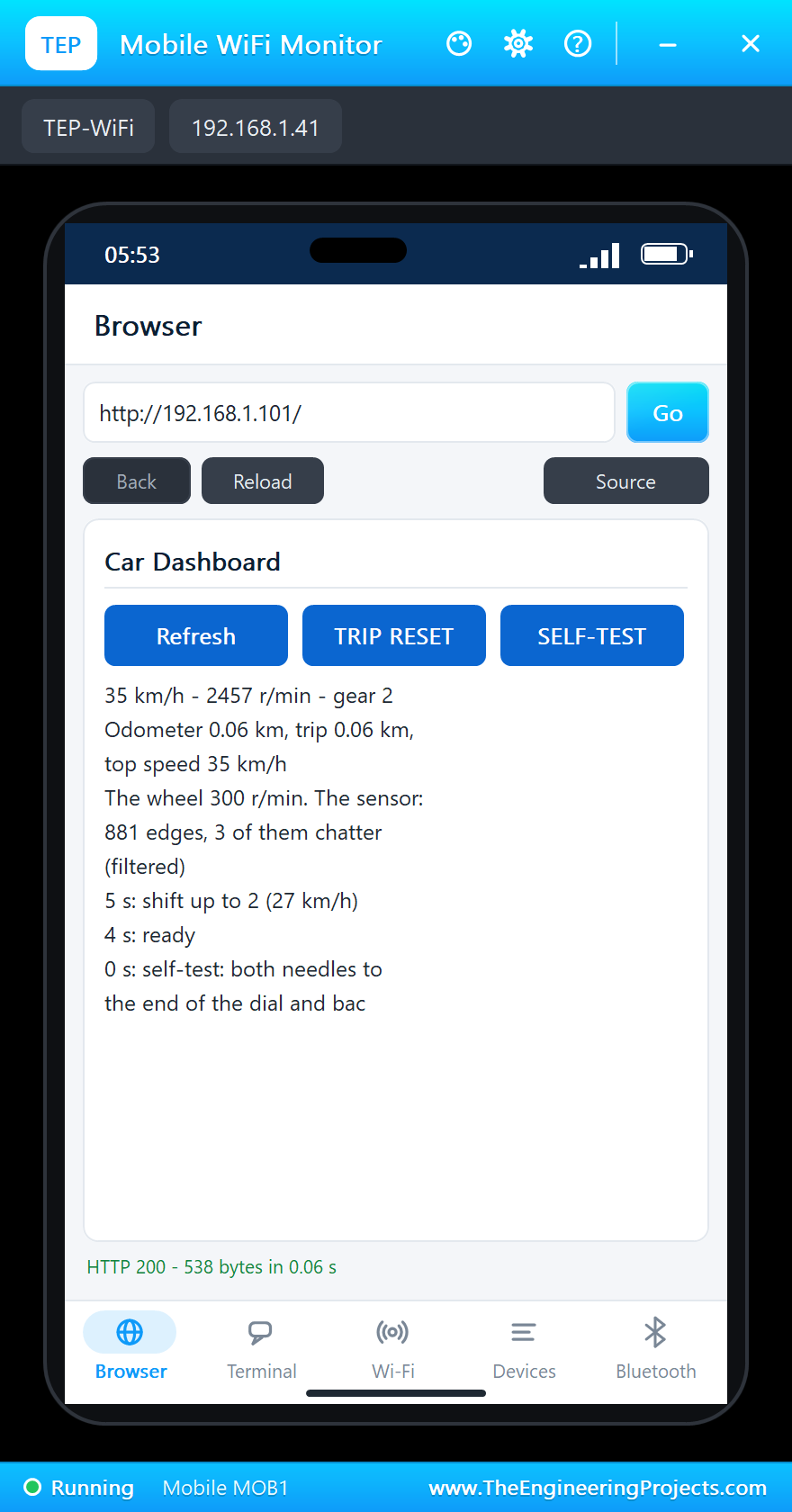
- Open the Laptop WiFi Monitor (PC1) or the Mobile WiFi Monitor (MOB1), press Go, and try TRIP RESET and SELF-TEST.
- Be patient: the simulation runs slower than real time, because the gauges' coils are simulated as analog loads under PWM.
Proteus Simulation Results
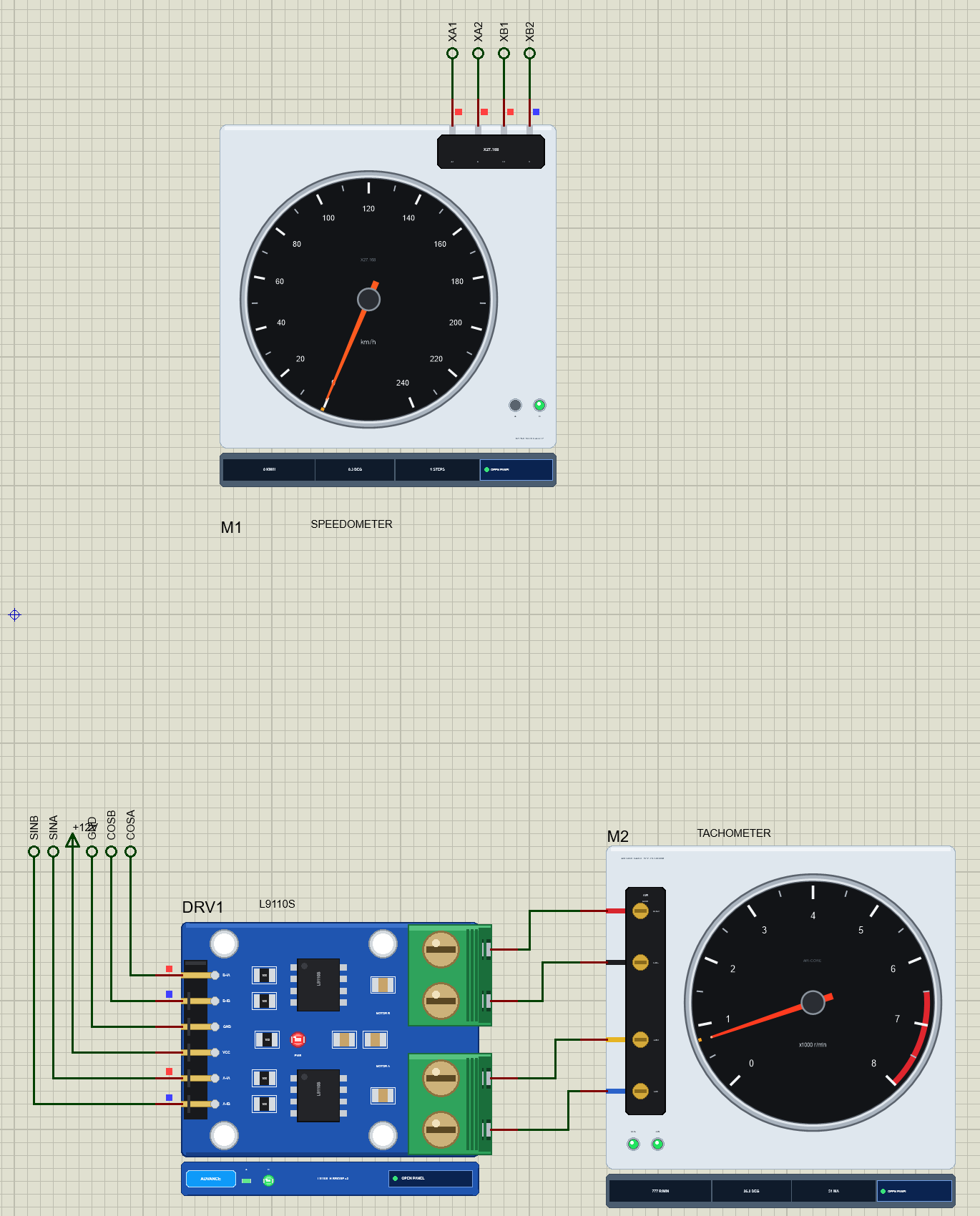
Here is one complete run of the simulation, with the numbers from our final test run; the times are the sketch's seconds since it started. At power-up the speedometer zeroed against its stop and both needles swept to the end of their dials and back, the self-test of a real instrument cluster; at 4 seconds the sketch said "ready".
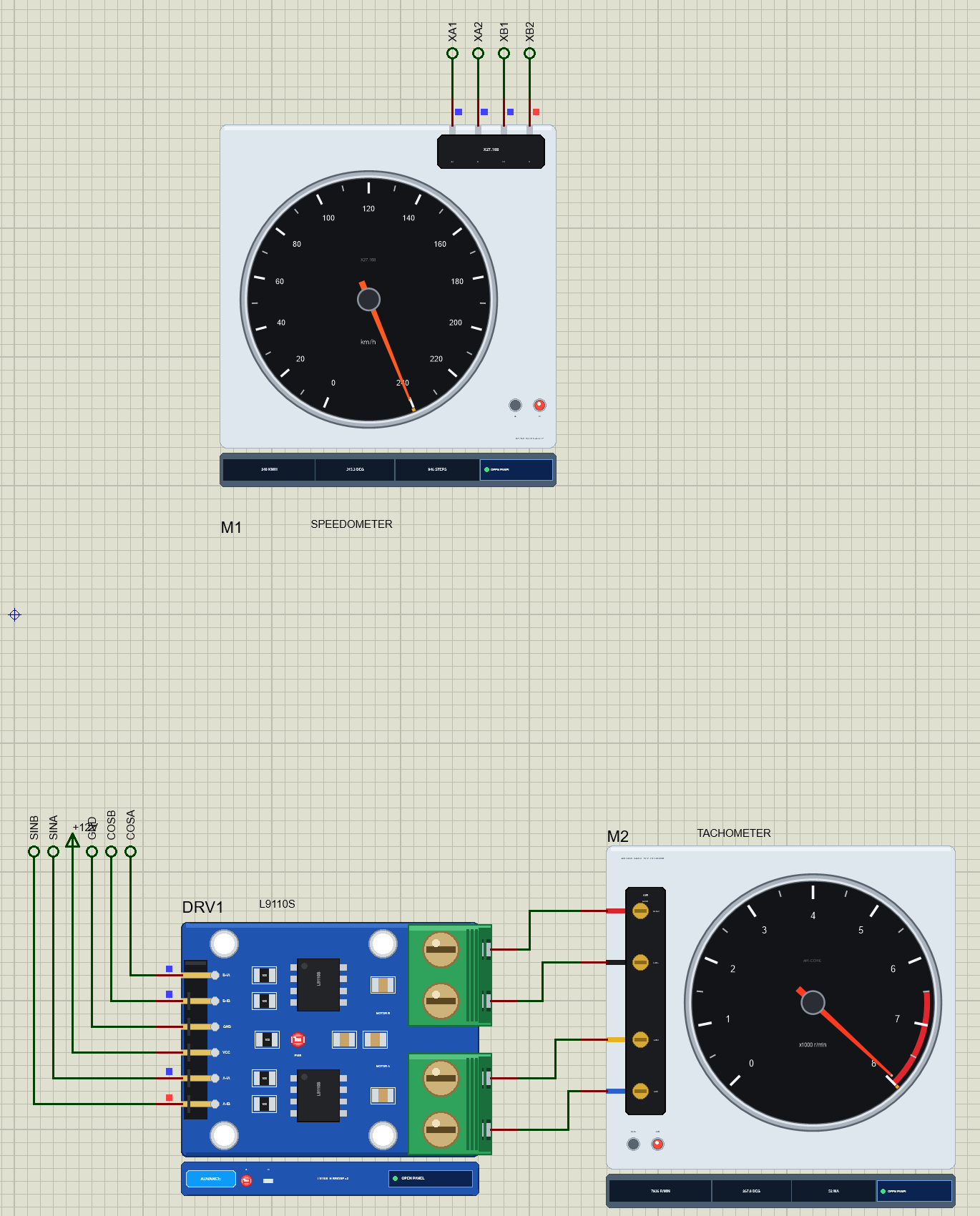
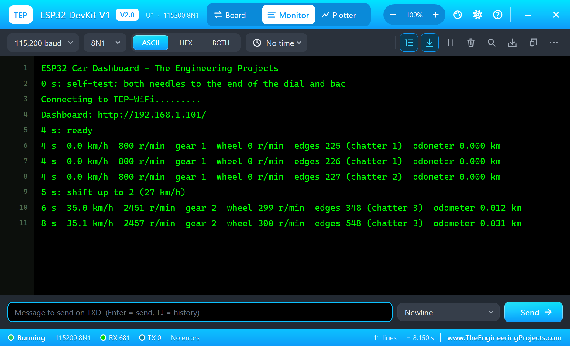
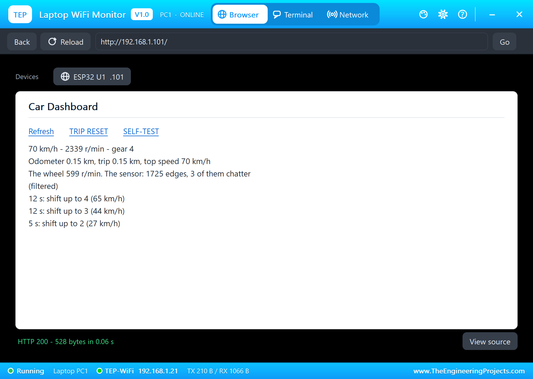
The LM393's pop-up turns the wheel at 300 r/min from the start, its default. "shift up to 2 (27 km/h)" at 5 seconds, then a steady 35.1 km/h and 2,457 r/min in gear 2, exactly 300 x 1.95 x 60 / 1,000 km/h and 300 x 2.10 x 3.90 r/min.
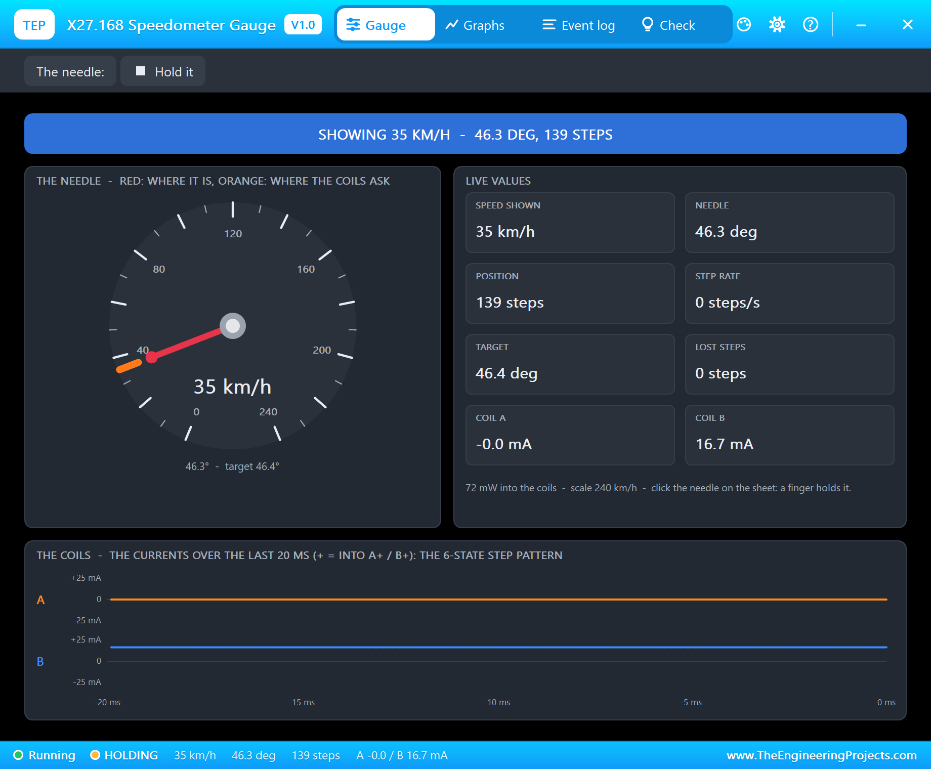
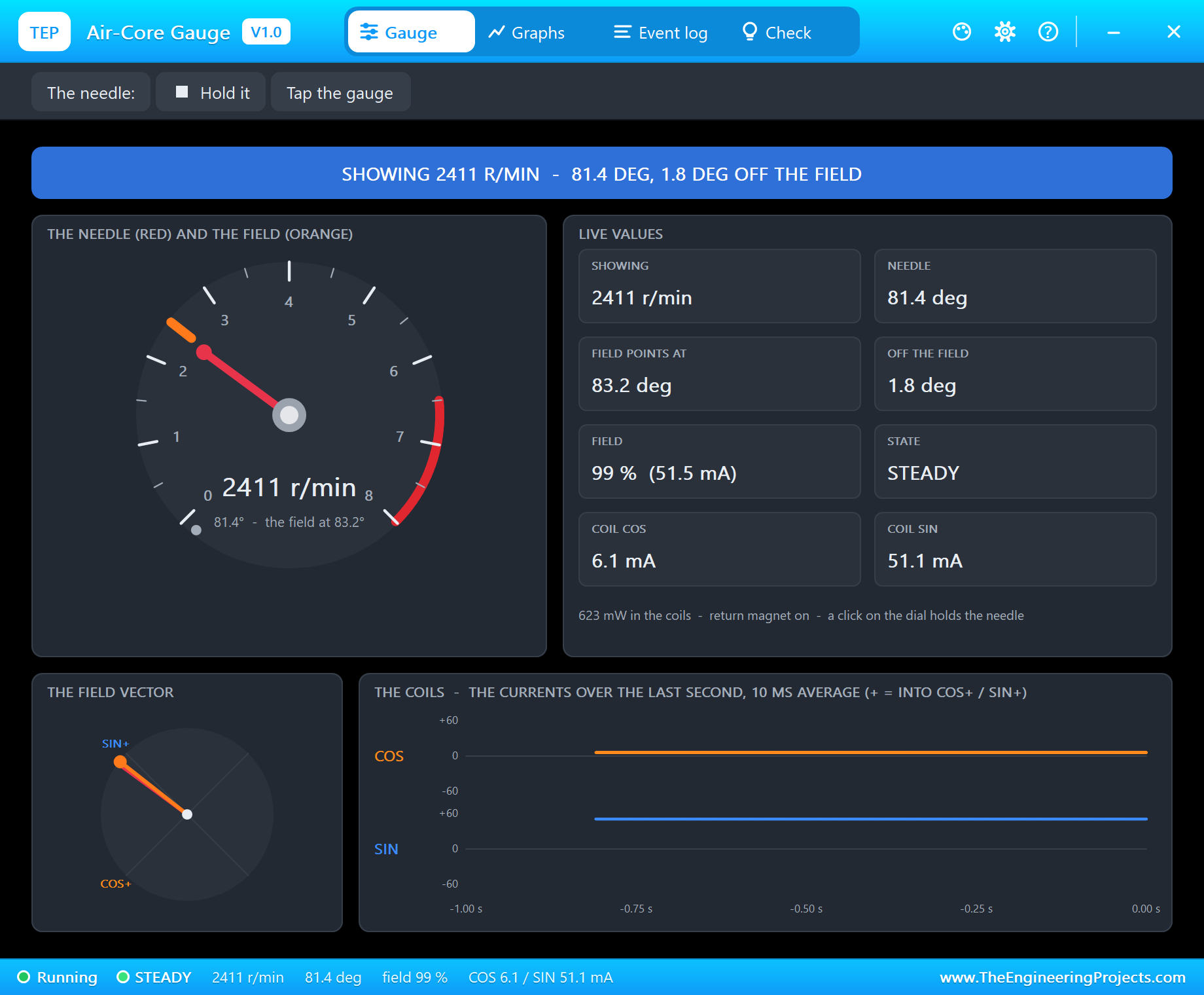
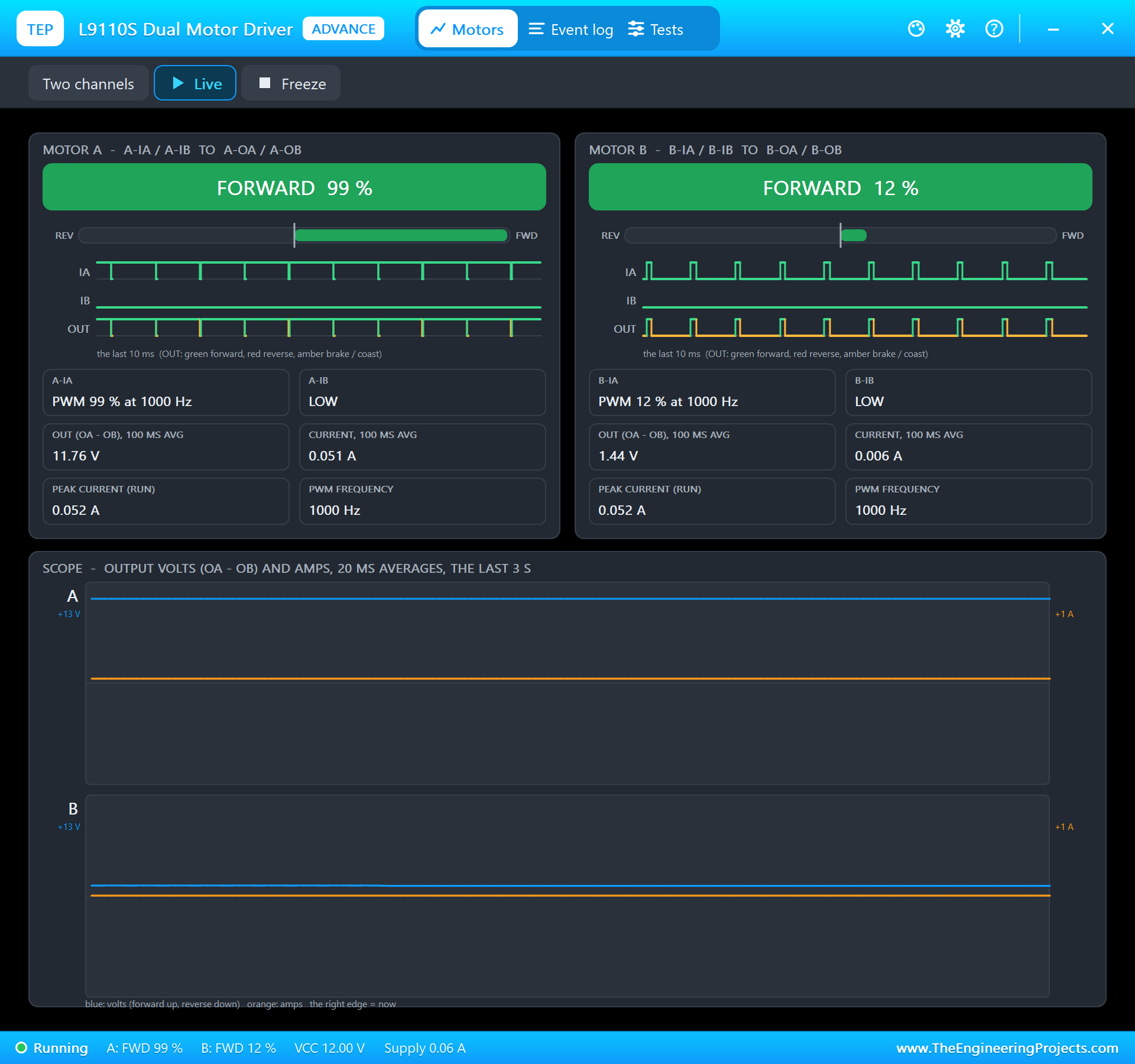
Faster: 70 km/h in Fourth
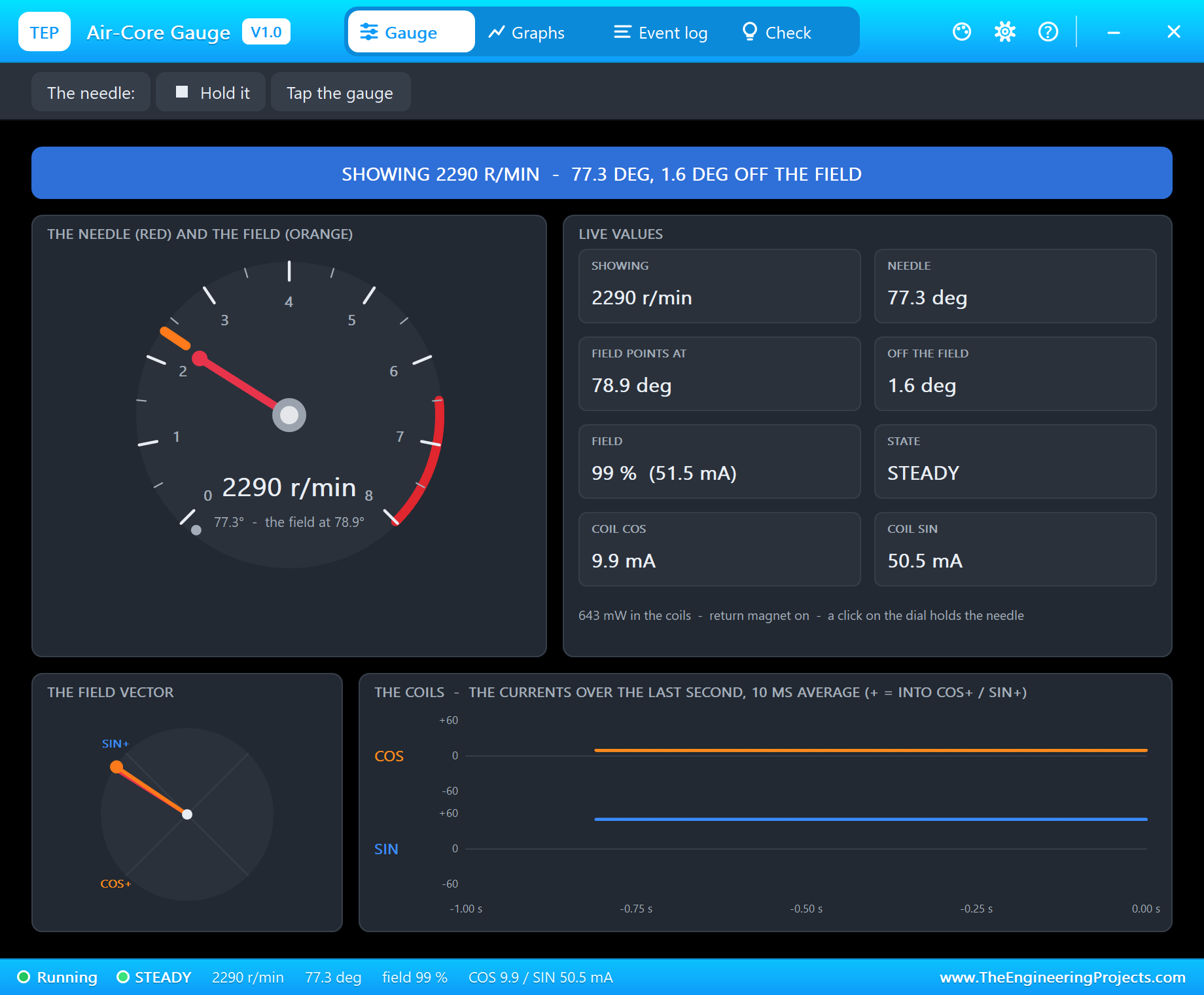
600 r/min on the wheel: at 12 seconds "shift up to 3" and "shift up to 4", then 70.2 km/h and 2,340 r/min. The speedometer's pop-up showed 277 steps, 92.3 degrees, the worked example's 276 steps rounded from the measured speed, with no lost step and 16.7 mA in each coil, as the simulated pins drive close to 5 V; on a real 3.3 V ESP32 it is about 13 mA. The tachometer showed 2,290 r/min: its field pointed at 78.9 degrees, 2,338 r/min, and the needle sat 1.6 degrees behind it, pulled by the return magnet that brings the needle home when the power goes. The coils took 9.9 and 50.5 mA, the cosine and the sine of 78.9 degrees.
175 km/h and the Overspeed Warning
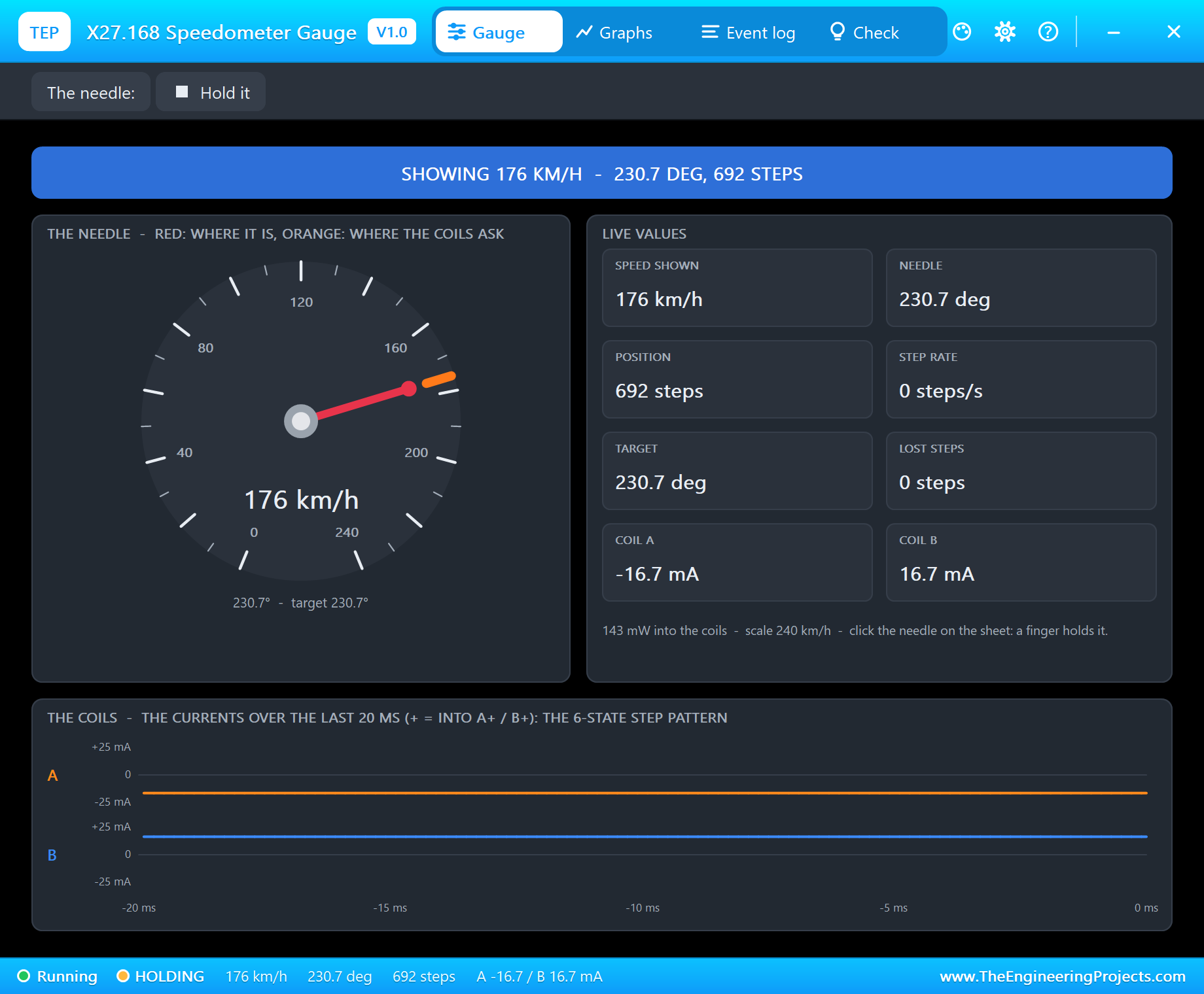
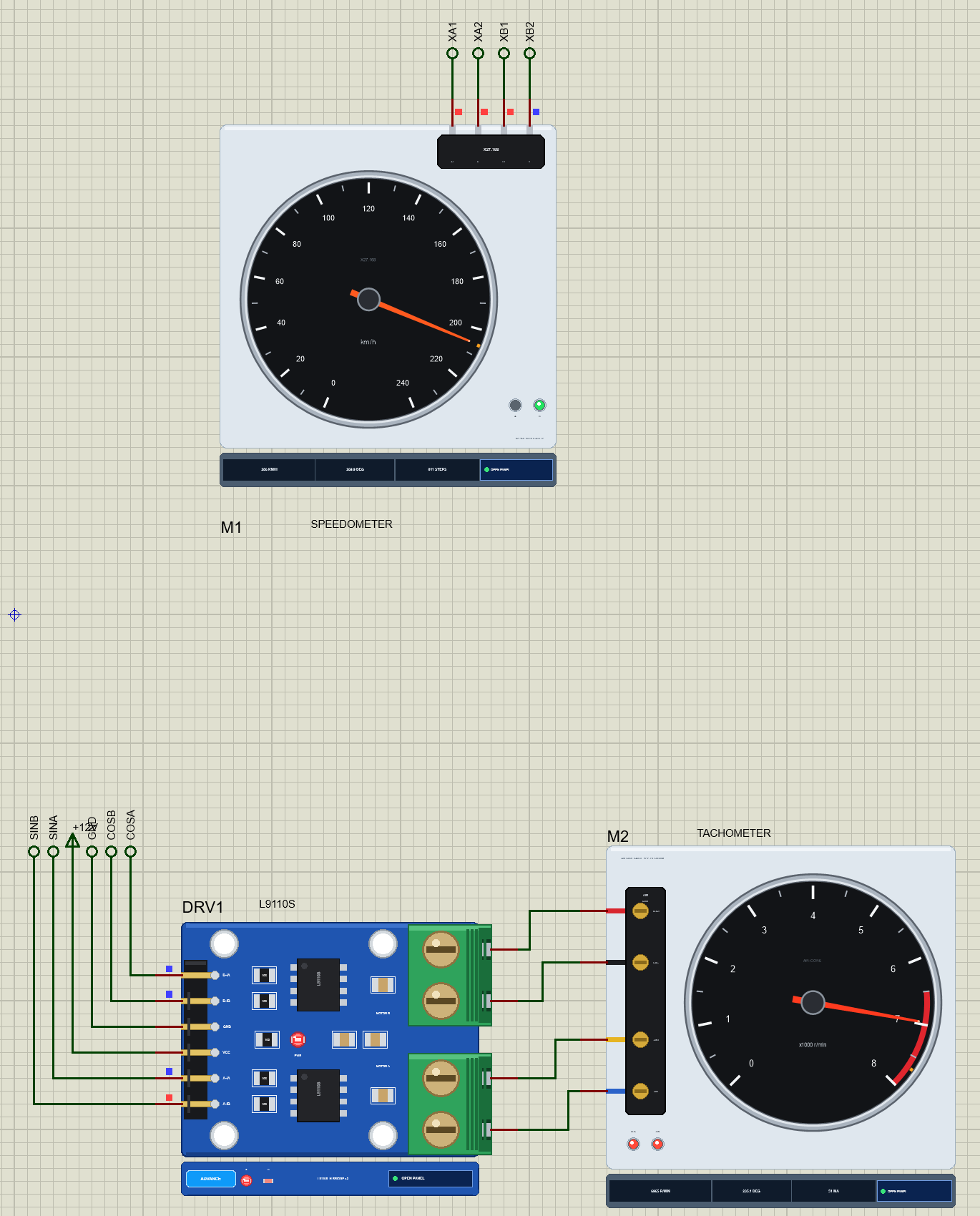
1,500 r/min: "shift up to 5" at 16 seconds and "OVERSPEED: 126 km/h" at 17 seconds as the speed climbed through the limit, then 175.5 km/h and 4,679 r/min. The speedometer stood at 692 steps, 230.7 degrees; the tachometer at 4,662 r/min, its COS coil now taking -47.6 mA and its SIN coil 19.0 mA: past 90 degrees the cosine is negative, so the L9110S drove motor B in reverse at 92 percent and motor A forward at 37 percent. The sensor's pop-up showed 500 slots a second and no extra edges: above about 200 r/min the comparator does not chatter.
Slowing Down and the Chatter at a Crawl
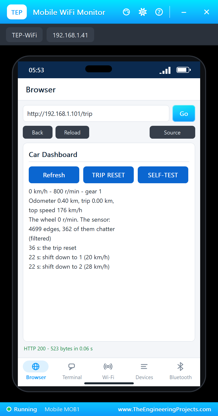
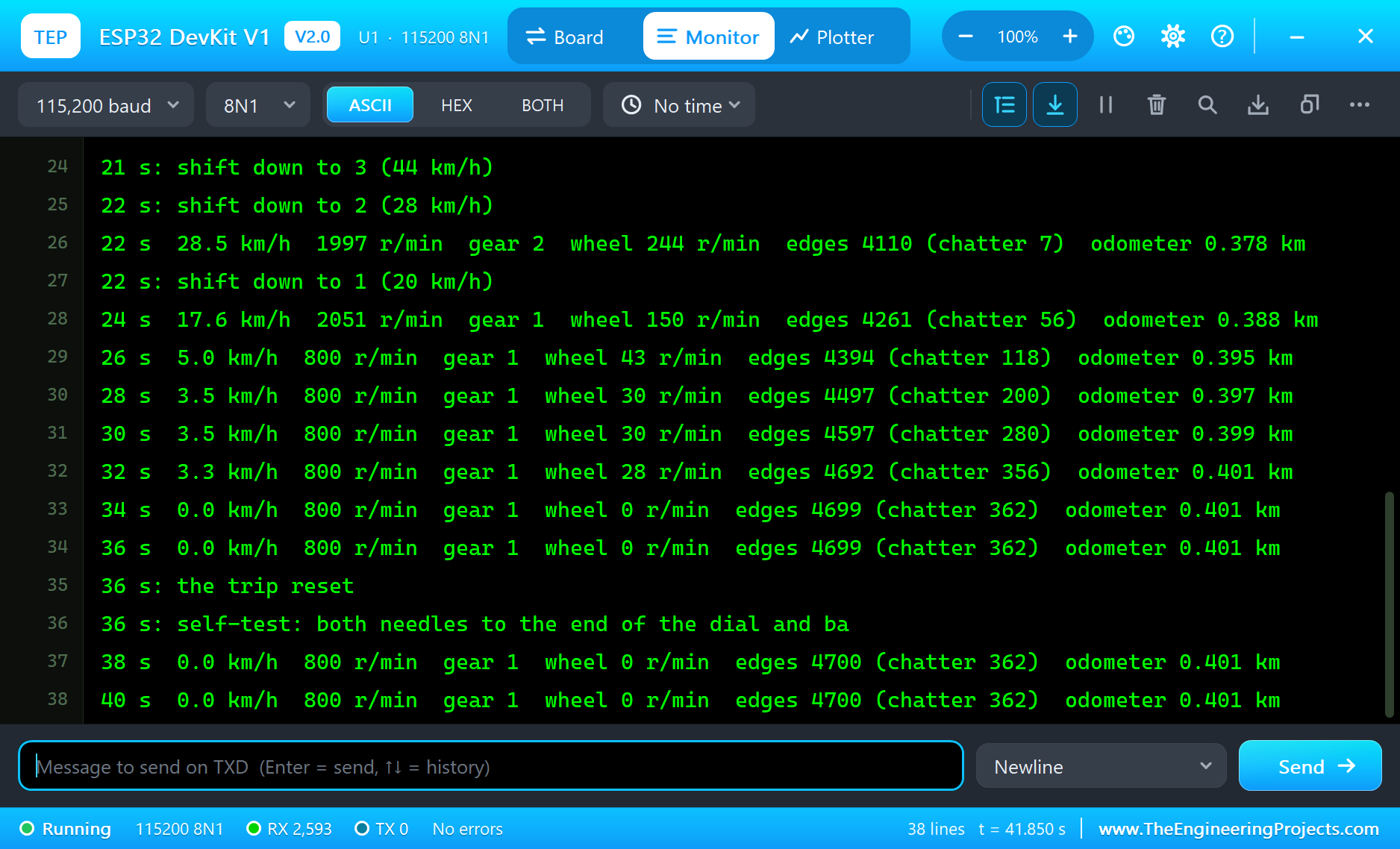
150 r/min: "shift down to 4, 3, 2, 1" at 21 and 22 seconds, one gear at a time, then 17.6 km/h and 2,051 r/min in first. At 30 r/min the LM393 showed what our sketch is up against: 10 true slots a second, but 50 falling edges on D0, 400 percent extra, so a plain count would read 150 r/min. The sketch read 30 r/min, 3.5 km/h, the engine at its 800 r/min idle, and by the end it had filtered 362 chatter edges. The first versions of this sketch read 472 km/h and then exactly double at this speed; the rule that reads D0 once a burst is over got it right.
Stop, Trip Reset and Self-Test
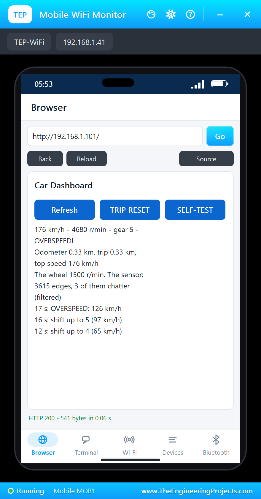
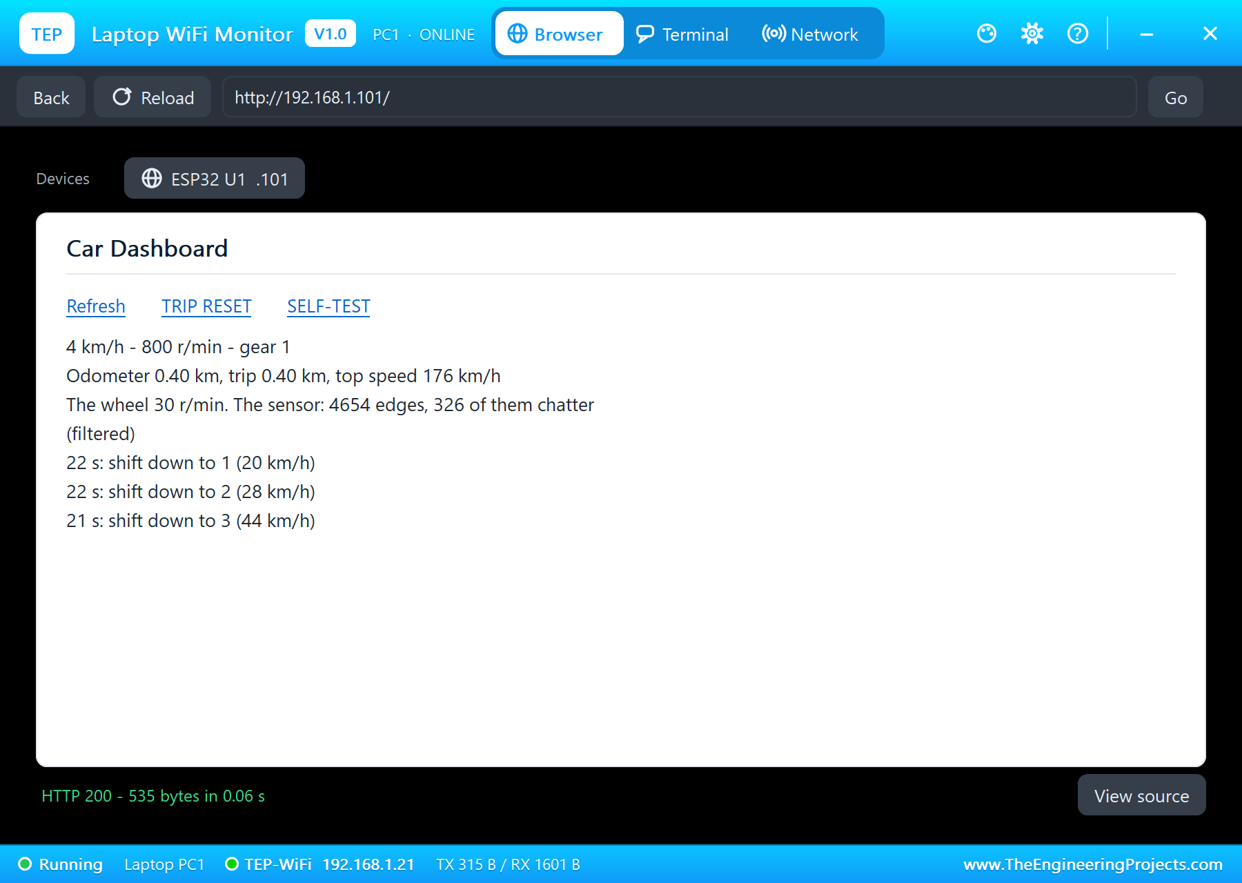
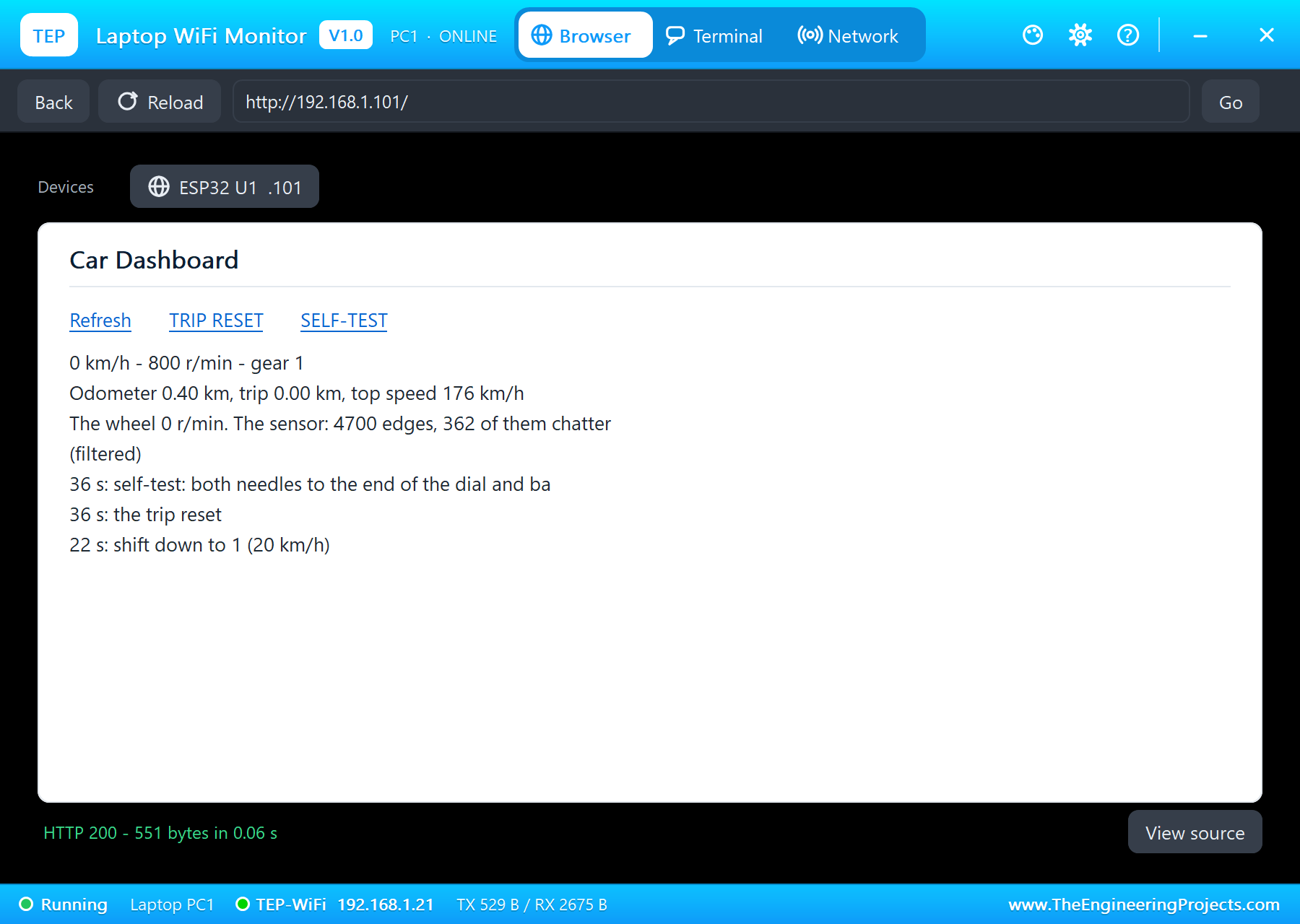
Stop: one second without a slot and the speed read 0.0 km/h at 34 seconds, the tachometer back at the idle. TRIP RESET on the phone at 36 seconds set the trip to zero while the odometer kept its 0.401 km, and SELF-TEST on the laptop swept both needles once more. 42 seconds of simulation took about 10 minutes on our PC with all the captures.
Download the Project Files
Click the button below to download IoT-Car-Dashboard-ESP32-Proteus-Simulation-v1.0.zip (about 4.0 MB, without the source code of the models):
IoT Car Dashboard with ESP32 - Proteus Simulation V1.0- Proteus Simulation: ESP32-Car-Dashboard.pdsprj, the compiled HEX file and copies of the models.
- Arduino Code: ESP32_Car_Dashboard.ino, the complete sketch.
- Proteus Library Files: the LIB files of the ESP32 DevKit V1, the two gauges, the L9110S, the LM393 and the two WiFi Monitors.
- Proteus Model Files: the DLL models.
- README.txt: the installation steps, the properties, the test results and the links to every library post.
No Proteus yet? Read How to Download and Install Proteus 7 and 8. New to libraries? Follow How to Install a New Library in Proteus.
How to Install the Project Files
- Close Proteus and extract the whole zip file, for example to your Desktop.
- Copy the files from Proteus Library Files into the LIBRARY folder of Proteus.
- Copy the files from Proteus Model Files into the MODELS folder.
- Start Proteus and open the project from the Proteus Simulation folder.
Changing the Code
Open the sketch in the Arduino IDE with the ESP32 boards installed, compile it, export the compiled binary and set the board's PROGRAM property to the new file. Your own car's numbers are at the top: the tyre, the ratios, the shift points and the overspeed limit. The same sketch runs on a real ESP32 DevKit V1. For our other ESP32 project with PWM and a dashboard, see the IoT RGB Mood Lamp with ESP32.
Ideas to Extend the Project
- Read the real speed and engine speed from a car's OBD-II port with a CAN transceiver.
- Add a fuel gauge: one more air-core movement and a float sensor.
- Log every trip to the ESP32's flash: the distance, the top speed and the average.
- Add a buzzer for the overspeed warning and a set speed you choose from the dashboard.
- Show a 0 to 100 km/h timer on the dashboard.
- Use two slotted sensors 90 degrees apart and tell forward from reverse.
From Simulation to Real Hardware
- Power the LM393 from 3.3 V: its output then never exceeds what an ESP32 pin accepts.
- Protect the pins: the X27.168's coils are inductive; add the small diodes or the dedicated driver chips gauge makers use for long life.
- Give the 12 V a clean supply: a car's 12 V spikes well above 12 V; regulate it for the L9110S and the gauge.
- Calibrate the speed: measure your tyre's real rolling circumference; a worn tyre is a few percent smaller.
- Zero at every start: the X27.168 has no position sensor, so the zeroing at power-up is what keeps it honest.
Troubleshooting
- The speed jumps at a crawl: the chatter; keep the 300 microsecond lockout.
- The speedometer is wrong after a reset: it skipped the zeroing; it has no idea where the needle is.
- The speedometer lags or loses steps: the steps are too fast; keep the ramp.
- The tachometer needle sticks at its pin: the field jumped more than 180 degrees; turn it in small steps.
- The tachometer reads backwards or 90 degrees off: COS and SIN, or a coil's + and -, are swapped.
- LM393 NO POWER in its pop-up: its VCC is not on the 5 V rail.
Limitations of the Simulation
- The wheel's speed comes from the LM393's pop-up; there is no car, no road and no load.
- The simulation runs slower than real time, because the gauges' coils and their PWM are simulated in detail.
- The network is simulated: the dashboard travels between the ESP32 and the two monitors inside Proteus; the times in this tutorial are simulation time.
- ESP32 is made by Espressif; the X27.168 is a Switec-style gauge stepper made by several companies. This project is not made or endorsed by them or by Labcenter.
So, that was all about the IoT Car Dashboard with ESP32 - Proteus Simulation. I hope it helps you build your own instrument cluster: a slotted sensor timed by an interrupt with a chatter filter, a gauge stepper driven straight from four pins, an air-core needle steered by sine and cosine, and a gearbox in a few lines of code, all tested in a simulation before you touch a car. More IoT projects with the ESP32 and the Raspberry Pi 5 are coming in this series. If you have any questions, ask in the comments and I will help you out. Till the next tutorial, take care and have fun!

Comments
0