


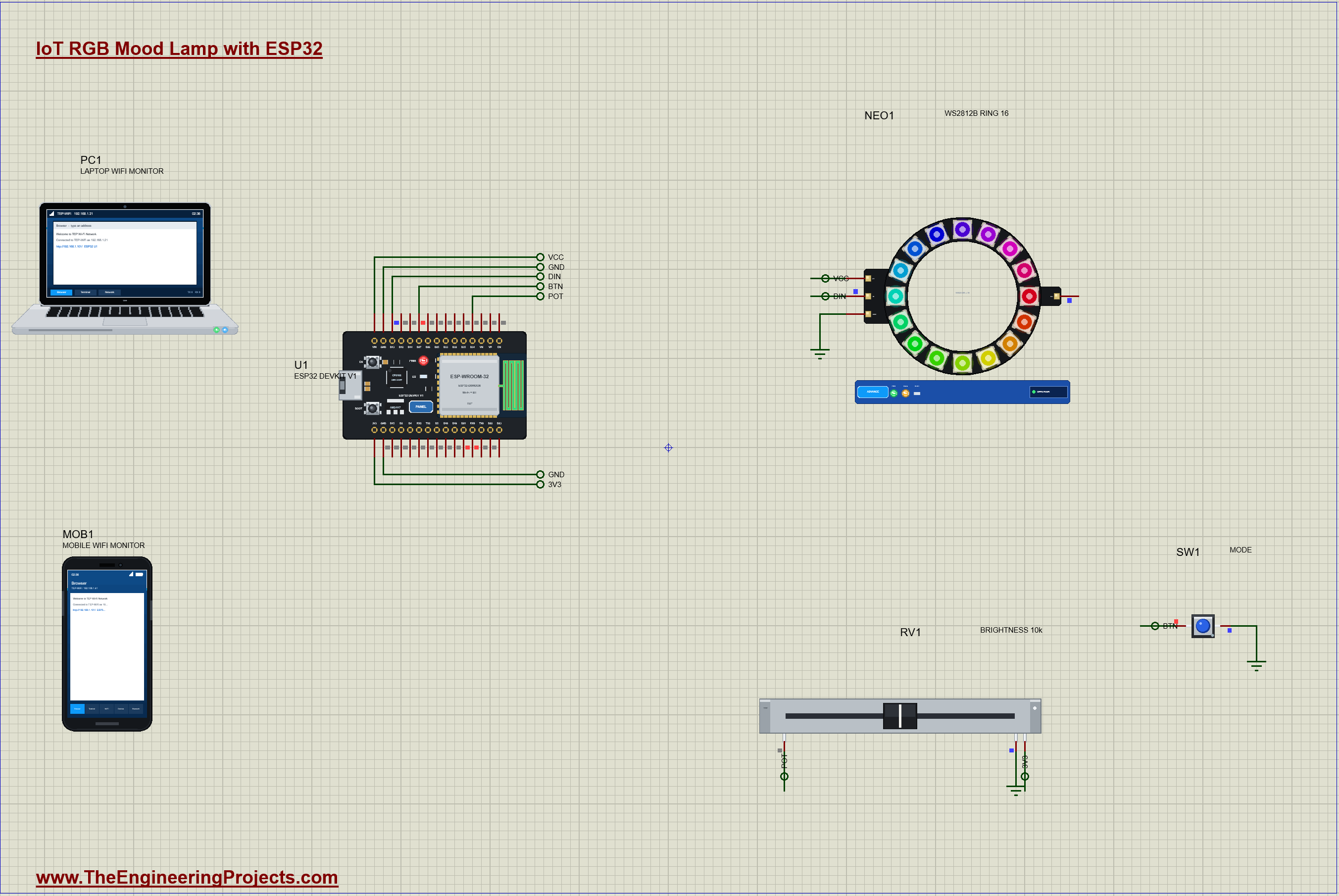
IoT RGB Mood Lamp with ESP32 - Proteus Simulation


Hello friends, I hope you all are doing great. Today, I am going to share the IoT RGB Mood Lamp with ESP32 - Proteus Simulation, the twenty-seventh project of our IoT Projects series. If you have searched for a Proteus simulation of an ESP32 driving WS2812B NeoPixel LEDs, here is a complete one. An ESP32 DevKit V1 drives a ring of 16 addressable RGB LEDs as a mood lamp: a slide potentiometer sets the brightness, a push button steps through six light modes, and a web dashboard picks the mode and the colour and starts a sleep timer that fades the lamp out.
Addressable LEDs such as the WS2812B, sold as NeoPixels, changed how people build lights: every LED has its own tiny controller, so one data wire sets the colour of every LED in a strip or a ring. In this tutorial, we will go through the circuit, learn how the WS2812B protocol packs 24 bits a LED into one wire at 800 kHz, mix any colour on the HSV colour wheel, read a slide potentiometer with the ESP32's 12-bit ADC, debounce a real push button whose contacts bounce, build six light effects and a fading sleep timer, walk through the Arduino sketch, and then run the simulation: a rainbow, the brightness up and down, FIRE and NIGHT from the button, colours and breathing from the dashboard, and the lamp falling asleep. At the end, you can download the project with the sketch and every library file.
NOTICE: Our team has put a lot of effort into this project: the circuit, the code and every part in the simulation are our own work, and you get them all free. Your feedback is the fuel that keeps us going, so please tell us what you think in the comments below. And if our free projects help you, you can buy us a coffee. So, let's get started with the IoT RGB Mood Lamp with ESP32 - Proteus Simulation:
What Does This Mood Lamp Do?
- Sixteen RGB LEDs on one wire: a WS2812B ring, any colour on every LED, 50 times a second.
- Six modes: SOLID, BREATHE (the colour fading in and out), RAINBOW (the colour wheel turning round the ring), FIRE (a warm flicker), NIGHT (a dim warm glow) and OFF.
- A real brightness knob: a 60 mm slide potentiometer read by the ESP32's ADC.
- A mode button: a tactile switch, debounced in software, steps to the next mode.
- Six colours from the dashboard: RED, GREEN, BLUE, WARM, COOL and PURPLE.
- A sleep timer: the lamp fades out and switches off by itself (30 seconds in the demo, 30 minutes on a real lamp).
It is a perfect first project with addressable LEDs and a good lesson in analog inputs and debouncing. In the simulation, you move the slider in its pop-up, press the button in its own pop-up, and watch every LED of the ring in the WS2812B's pop-up.
Components Used in the Proteus Simulation
All the parts come from our Proteus libraries, each with its own tutorial. The project zip at the end includes every LIB and DLL file.
| Part | Proteus device | Library post | Connection |
|---|---|---|---|
| ESP32 DevKit V1 | ESP32 DEVKIT V1 | ESP32 DevKit V1 Library for Proteus | U1, TEP-WiFi 192.168.1.101 |
| WS2812B ring of 16 LEDs | WS2812RING16ADVTEP | WS2812B NeoPixel Library for Proteus | NEO1, DIN on D13 |
| Slide potentiometer 60 mm | SLIDEPOT60TEP | Slide Potentiometer Library | RV1, the wiper on D34 |
| Push button (blue) | BUTTONBLUETEP | Push Button Library | SW1, D27 to GND |
| Laptop WiFi Monitor | LAPTOP WIFI MONITOR | Laptop WiFi Monitor | PC1 |
| Mobile WiFi Monitor | MOBILE WIFI MONITOR | Mobile WiFi Monitor | MOB1 |
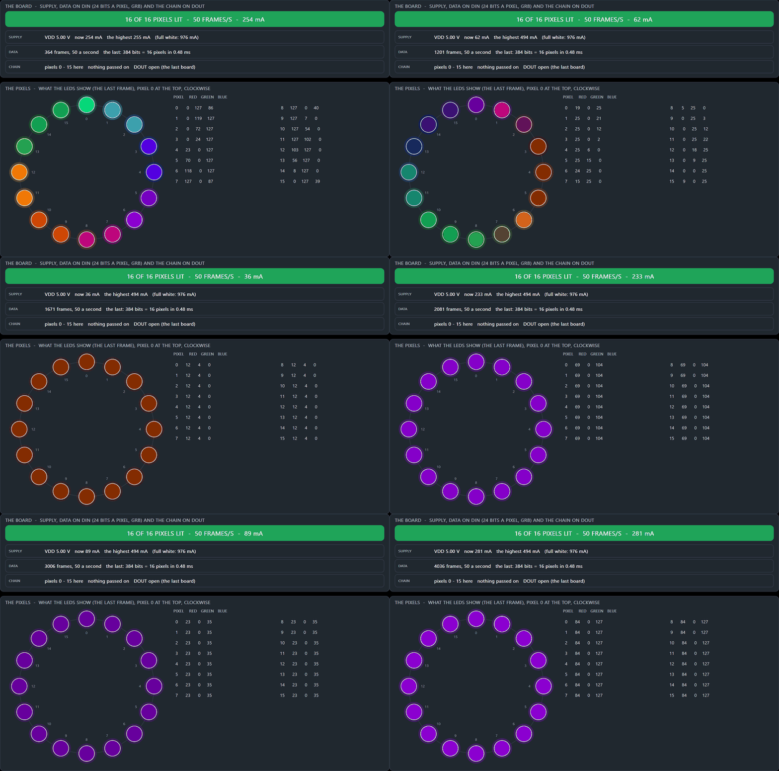
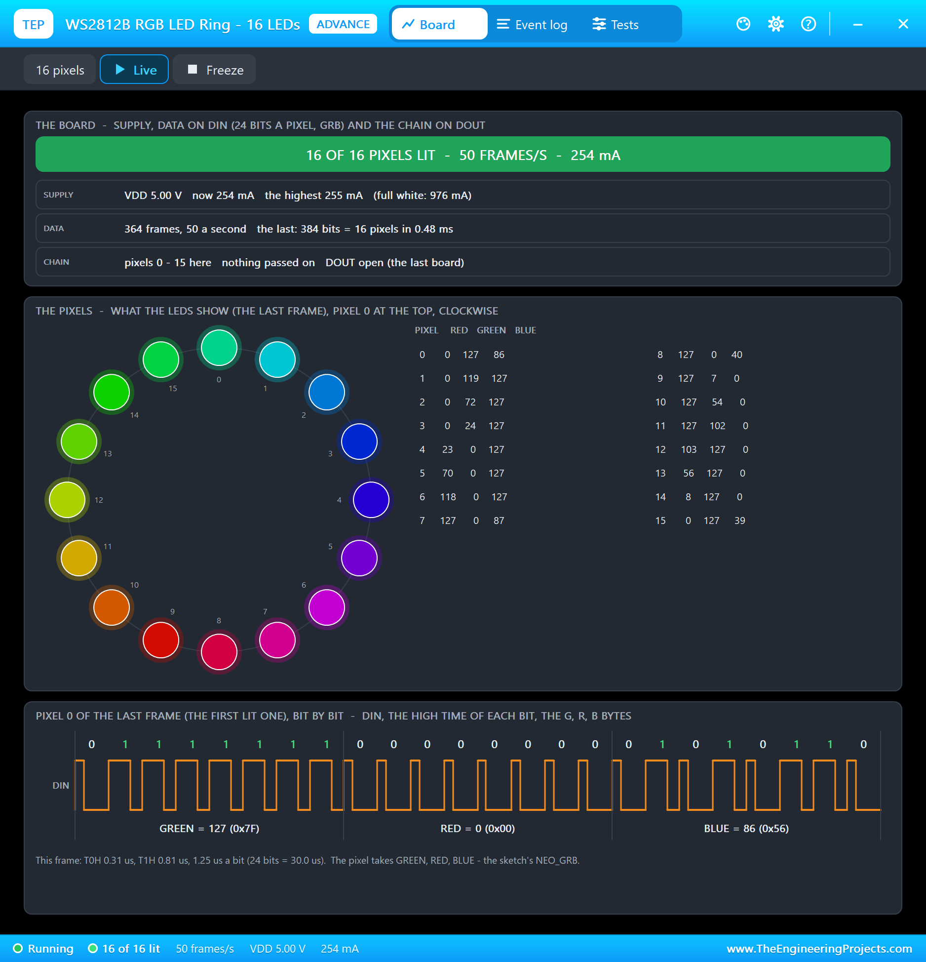
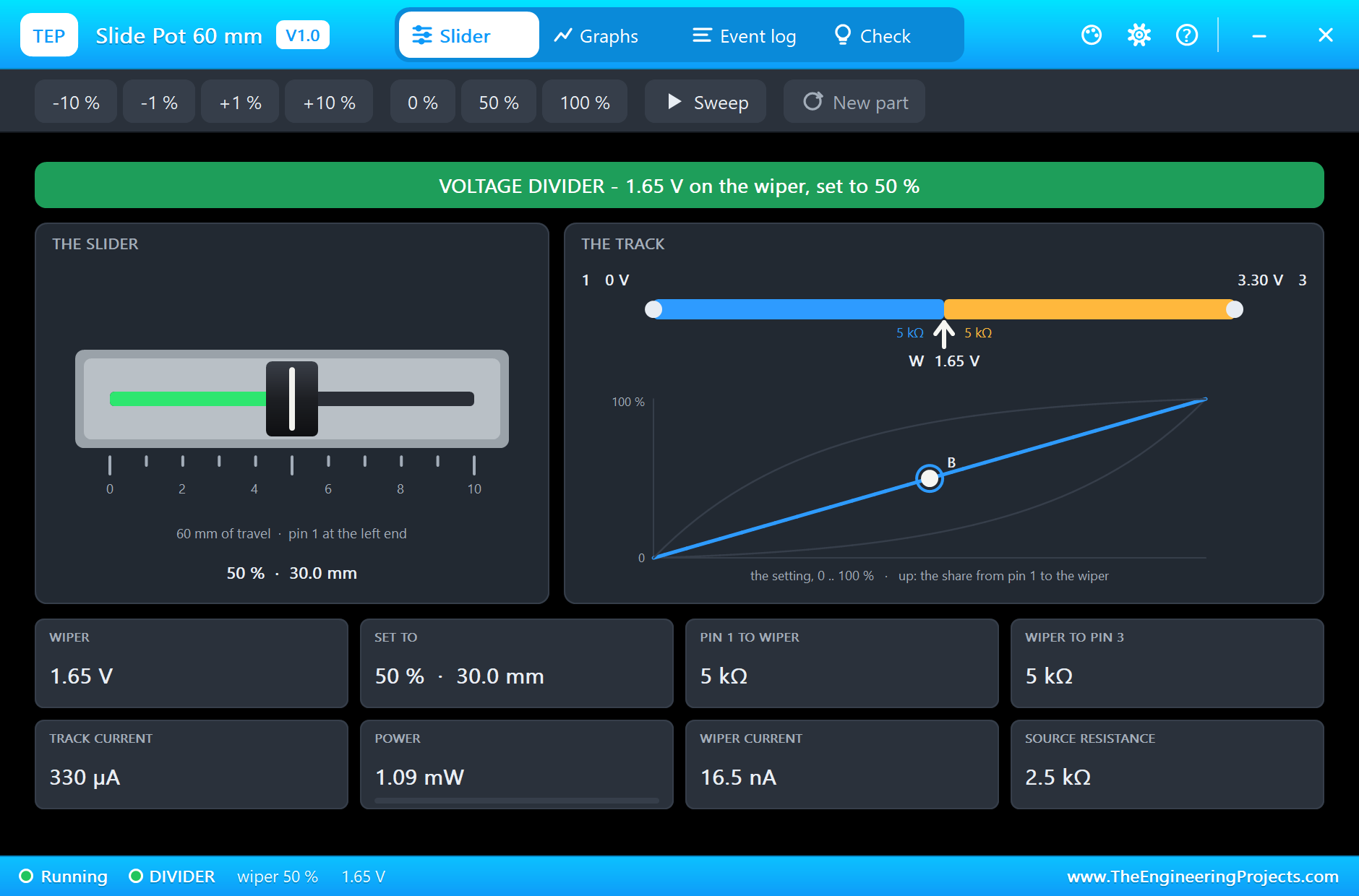
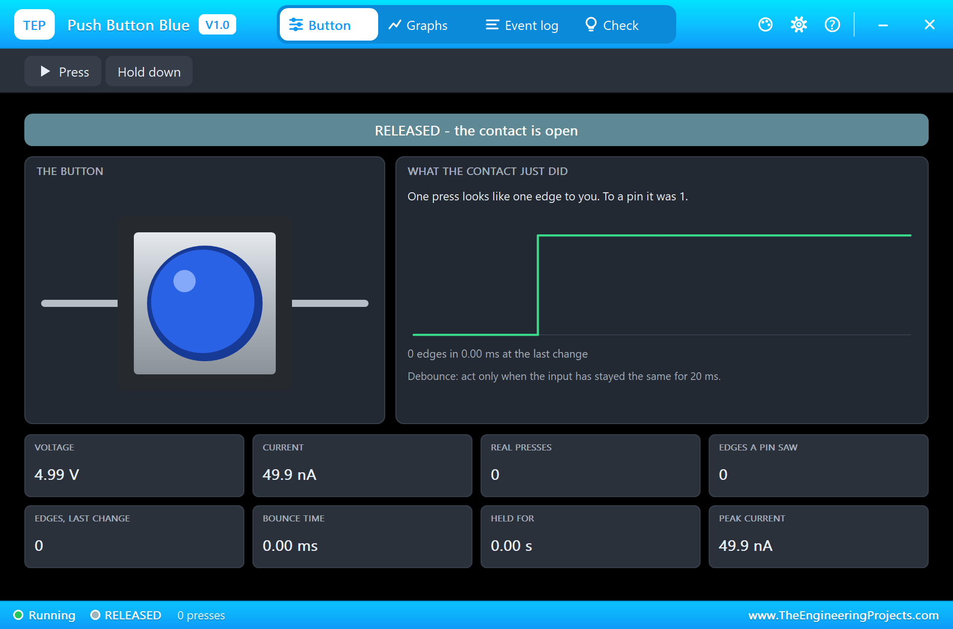
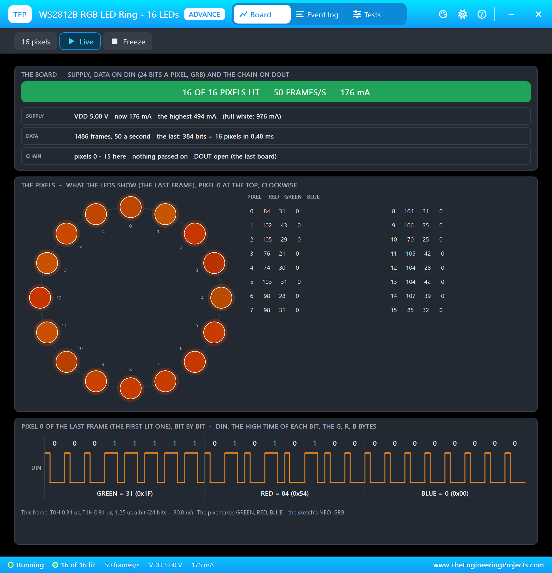
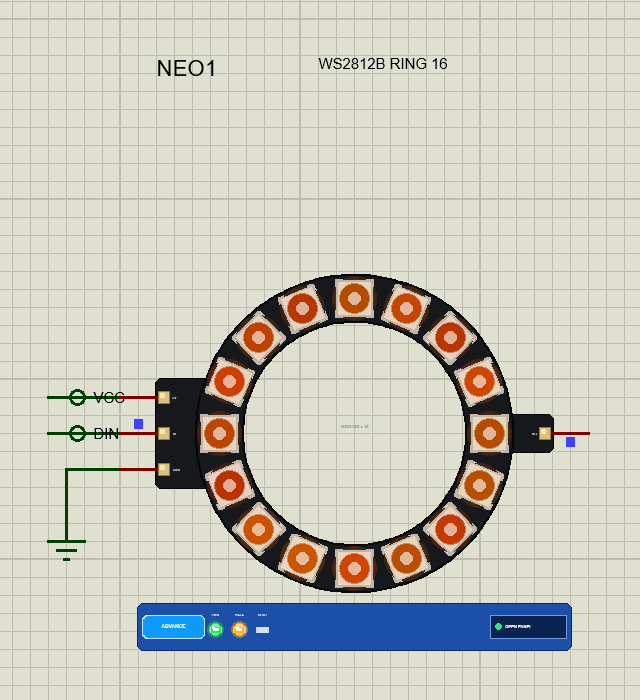
The ring, the slider and the button are models with pop-ups. The ring's pop-up shows every LED with its red, green and blue values, the frame rate, the supply current and the bits of the last frame. The slider's pop-up moves the slider (steps of 1 and 10 percent, 0, 50 and 100 percent, and a sweep) and draws the voltage divider. The button's pop-up presses the button and draws every edge its contacts make, the bounce included.
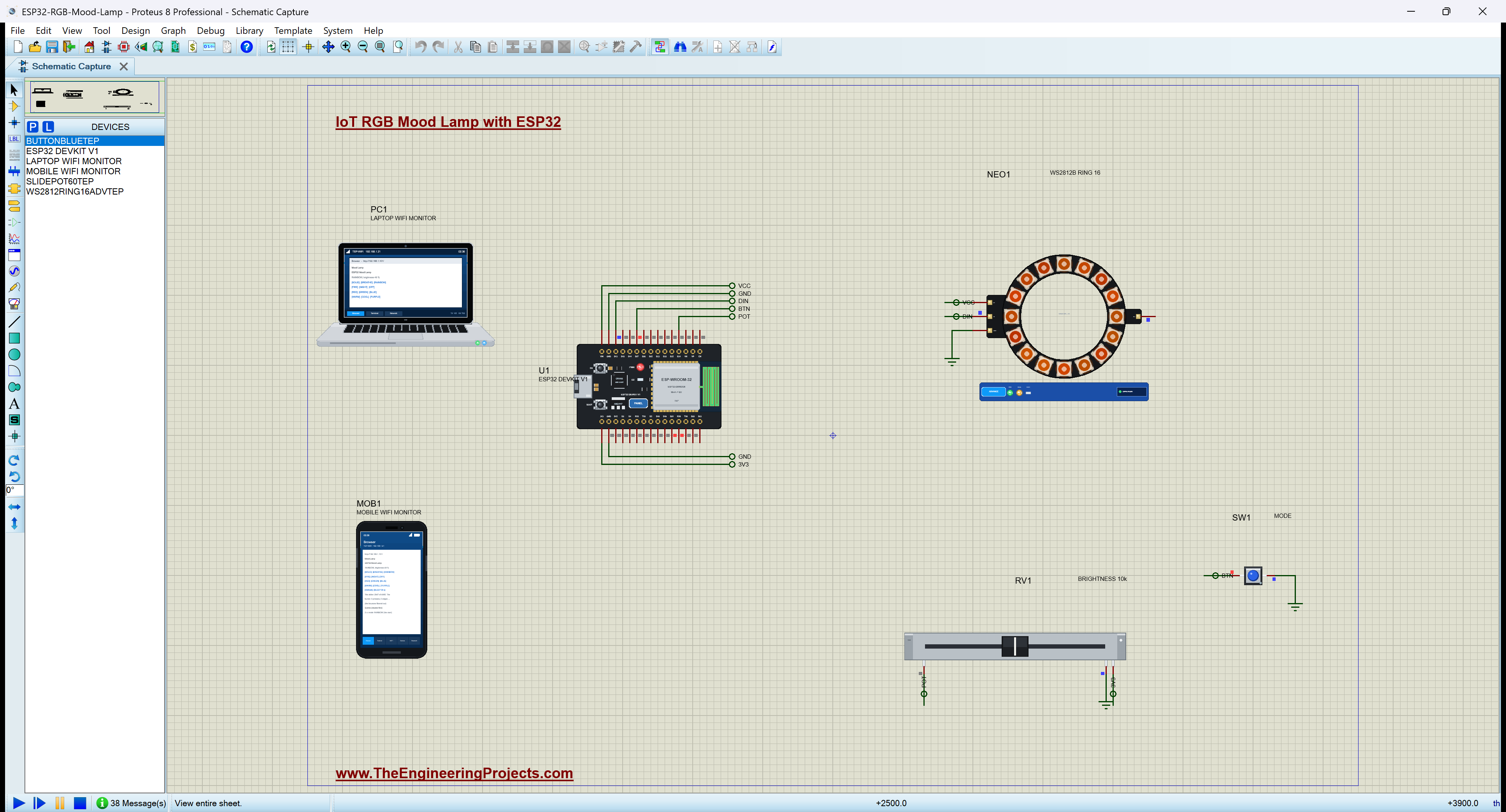
Proteus Simulation of the Mood Lamp: the Circuit
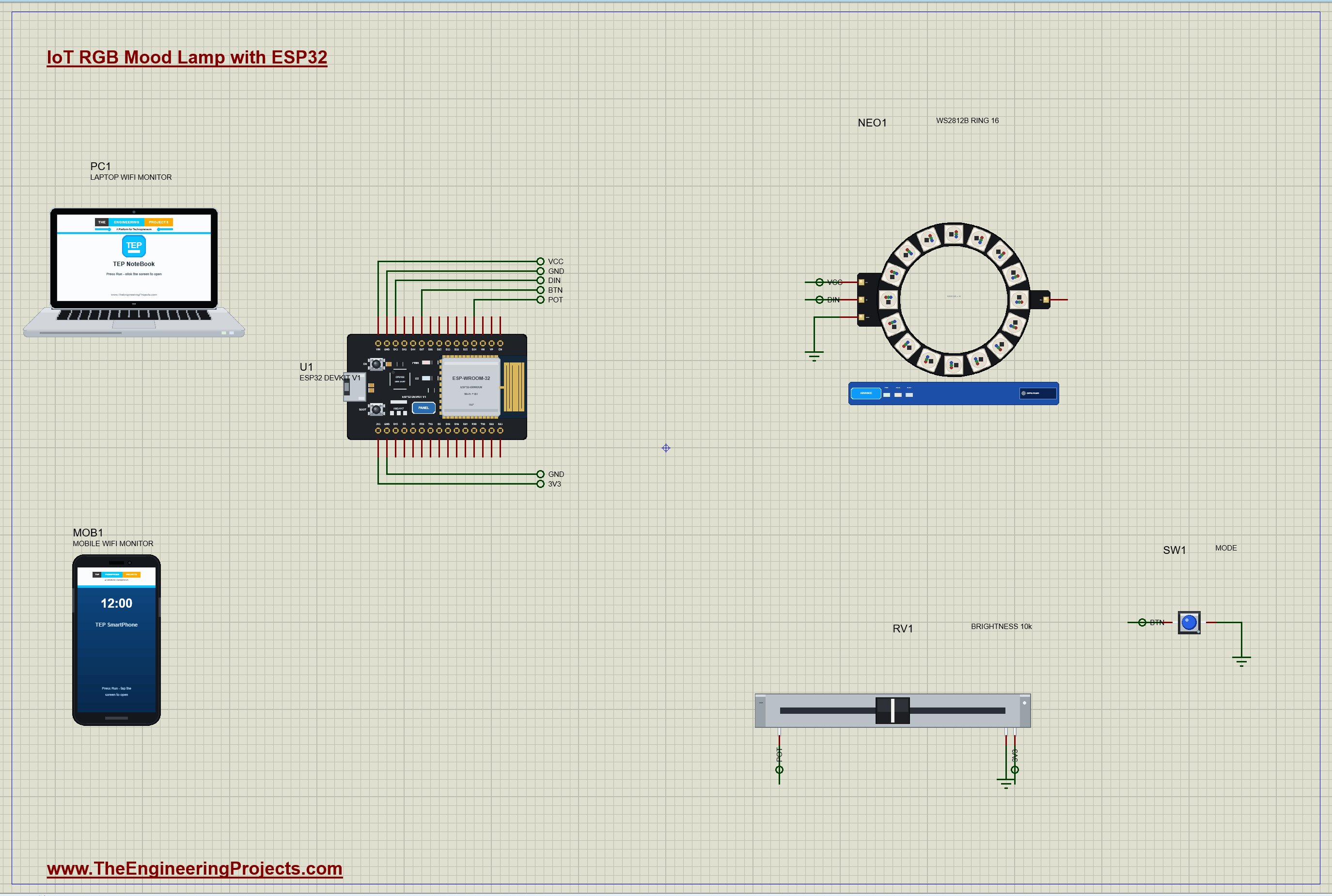
| Part | Pins | ESP32 DevKit V1 |
|---|---|---|
| NEO1 WS2812B ring | 5V / GND / DIN / DOUT | VIN (5 V) / GND / D13 / open (the end of the chain) |
| RV1 slide potentiometer | 1 / 3 / W (the wiper) | GND / 3V3 / D34 (ADC) |
| SW1 push button | 1 / 2 | D27 (INPUT_PULLUP) / GND |
The ring takes its power from VIN, the 5 V of the USB connector, and only its data from the ESP32. The slide potentiometer is a voltage divider between 3.3 V and ground: its wiper gives 0 to 3.3 V to D34, one of the ESP32's ADC pins. The button needs no resistor: the ESP32's internal pull-up holds D27 high, and the button pulls it to ground when pressed.
How the Mood Lamp Works
The WS2812B on One Wire
Each WS2812B is an RGB LED with a small controller inside. The ESP32 sends a stream of bits on one wire at 800 kHz, 1.25 microseconds a bit. A bit always starts high; a 0 is high for about 0.4 microseconds and a 1 for about 0.8, the rest of the 1.25 low. The first LED keeps the first 24 bits for itself, green, red and blue, 8 bits each, most significant first, and passes everything after them on through its DOUT pin; the second LED keeps the next 24, and so on. A low pause longer than 50 microseconds ends the frame, and every LED shows its new colour at once. Worked example: 16 LEDs x 24 bits = 384 bits, x 1.25 microseconds = 480 microseconds a frame, so even 50 frames a second take under 3 percent of the time.
Each LED draws up to about 20 mA per colour, 60 mA at full white, so 16 of them can draw nearly 1 A. That is why the ring has its own 5 V supply and why a lamp rarely runs every LED at full white.
Mixing Colours on the Colour Wheel
Red, green and blue at different strengths make any colour. For effects it is easier to think in hue: the colour wheel from red through yellow, green, cyan, blue and magenta back to red. The Adafruit NeoPixel library's ColorHSV() takes a hue from 0 to 65,535 for one turn of the wheel. The RAINBOW mode gives LED number i the hue i x 65,536 / 16, so the 16 LEDs show the whole wheel at once, and moves the start a little every frame: 262 steps a frame at 50 frames a second, one full turn in 5 seconds.
Brightness from the Slider
The ESP32's ADC turns 0 to 3.3 V into 0 to 4,095. The sketch maps that to a brightness of 0 to 255 and multiplies every colour by it. Worked example from our run: the slider in the middle gave 2,047, 1.65 V; 2,047 x 255 / 4,095 = 127, so the brightness was 127 of 255, 49 percent. Each mode multiplies once more by its own factor: BREATHE by a sine wave between 8 and 100 percent over 4 seconds, NIGHT by 10 percent, FIRE by a random flicker for every LED.
Debouncing a Real Button
A mechanical switch does not close cleanly: its contacts bounce for a few milliseconds, making and breaking many times, and a microcontroller fast enough to see each edge would count one press as several. The push button model reproduces this, with 5 ms of bounce by default. The sketch notes every edge, but accepts a new state only after the pin has stayed the same for 30 ms. So one press is one mode change, however many edges the contacts make.
The Sleep Timer
SLEEP on the dashboard starts a timer: the brightness falls in a straight line from the slider's level to nothing over 30 seconds, then the mode switches to OFF. On a real bedside lamp the same code would use 30 minutes.
The Arduino Code Explained
The whole sketch is included in the download. It uses the Adafruit NeoPixel library and the ESP32's WiFi and WebServer libraries. At the top are the pins and the timings:
const byte RING_PIN = 13, POT_PIN = 34, BUTTON_PIN = 27;
const byte N = 16;                           // LEDs on the ring
const unsigned long DEBOUNCE_MS = 30;        // the button must stay put this long
const unsigned long SLEEP_MS = 30000;        // the sleep timer (the demo; 30 minutes on a real lamp)
Adafruit_NeoPixel ring(N, RING_PIN, NEO_GRB + NEO_KHZ800);The Button
  if (now != lastRead) { lastRead = now; lastChange = millis(); bounces++; }       // every edge, the bounces too
  if (millis() - lastChange >= DEBOUNCE_MS && now != buttonState) {               // still for 30 ms: a real change
setMode((Mode)((mode + 1) % 6), "the button");The Brightness and the Effects
  potRaw = analogRead(POT_PIN);
  bright = map(potRaw, 0, 4095, 0, 255);
float s = (sin(2 * PI * (t % 4000) / 4000.0) + 1) / 2;
px = scaled(c.r, c.g, c.b, level * (0.08 + 0.92 * s)); break; uint32_t w = ring.ColorHSV(hue0 + i * 65536L / N); byte f = 140 + random(116);
px = scaled(255, 70 + random(40), 0, (uint32_t)level * f / 255); break;After the loop has set all 16 LEDs, ring.show() sends the whole frame on D13. The sleep timer's factor goes down in a straight line:
return 255 - (uint32_t)255 * gone / SLEEP_MS; if ((long)(millis() - nextFrame) >= 0) { nextFrame += 20; frame(); } // 50 frames a secondThe dashboard has fourteen addresses, but the sketch registers only two handlers: everything that is not / or /data goes to onNotFound(), which is the same dashboard handler, and it reads the address itself with server.uri(). One handler, one place to add a new mode:
server.onNotFound(handleRoot); // every other address (the modes, the colours, /sleep): the dashboard reads itThe pages are / (the dashboard), the six modes (/solid, /breathe, /rainbow, /fire, /night, /off), the six colours (/red, /green, /blue, /warm, /cool, /purple), /sleep and /data (JSON). A colour also switches to SOLID, except in BREATHE, which keeps breathing in the new colour.
How to Run the Proteus Simulation
- Download the project zip below and install the library files (the steps are under the download button).
- Open ESP32-RGB-Mood-Lamp.pdsprj from the Proteus Simulation folder. Keep the HEX and the DLL files next to it.
- Press Play. The ring turns in the RAINBOW mode at half brightness.
- Move the slider in its pop-up (RV1): 100 percent, 0 percent, +10 percent.
- Press the button in its pop-up (SW1) to step through the modes.
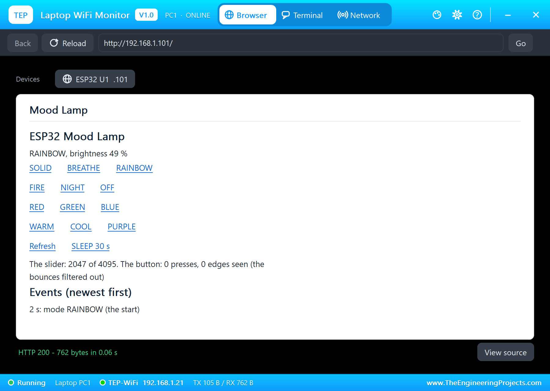
- Open the Laptop WiFi Monitor (PC1) or the Mobile WiFi Monitor (MOB1), press Go, and try the colours, BREATHE and SLEEP 30 s.
Proteus Simulation Results
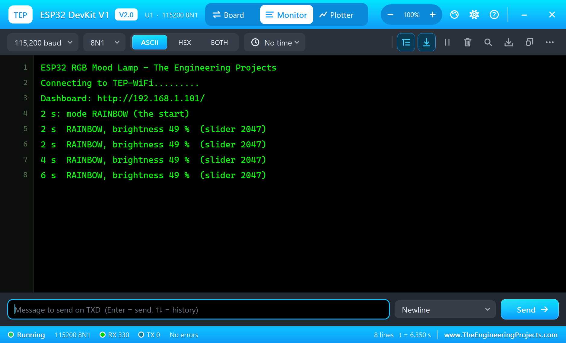
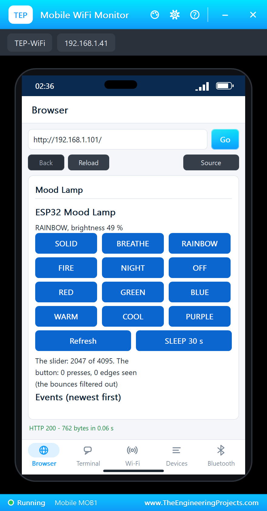
Here is one complete run of the simulation, with the numbers from our final test run; the times are the sketch's seconds since it started. The ESP32 joined TEP-WiFi, printed its dashboard address, http://192.168.1.101/, and at 2 seconds started in the RAINBOW mode. The slider stood in the middle: 2,047 of 4,095, a brightness of 49 percent.
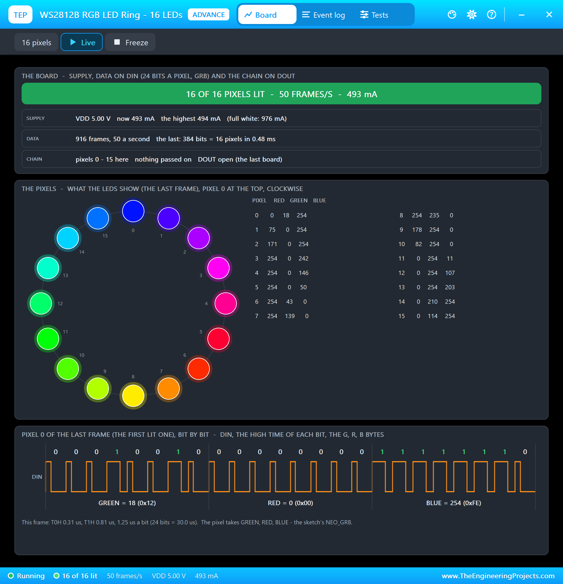
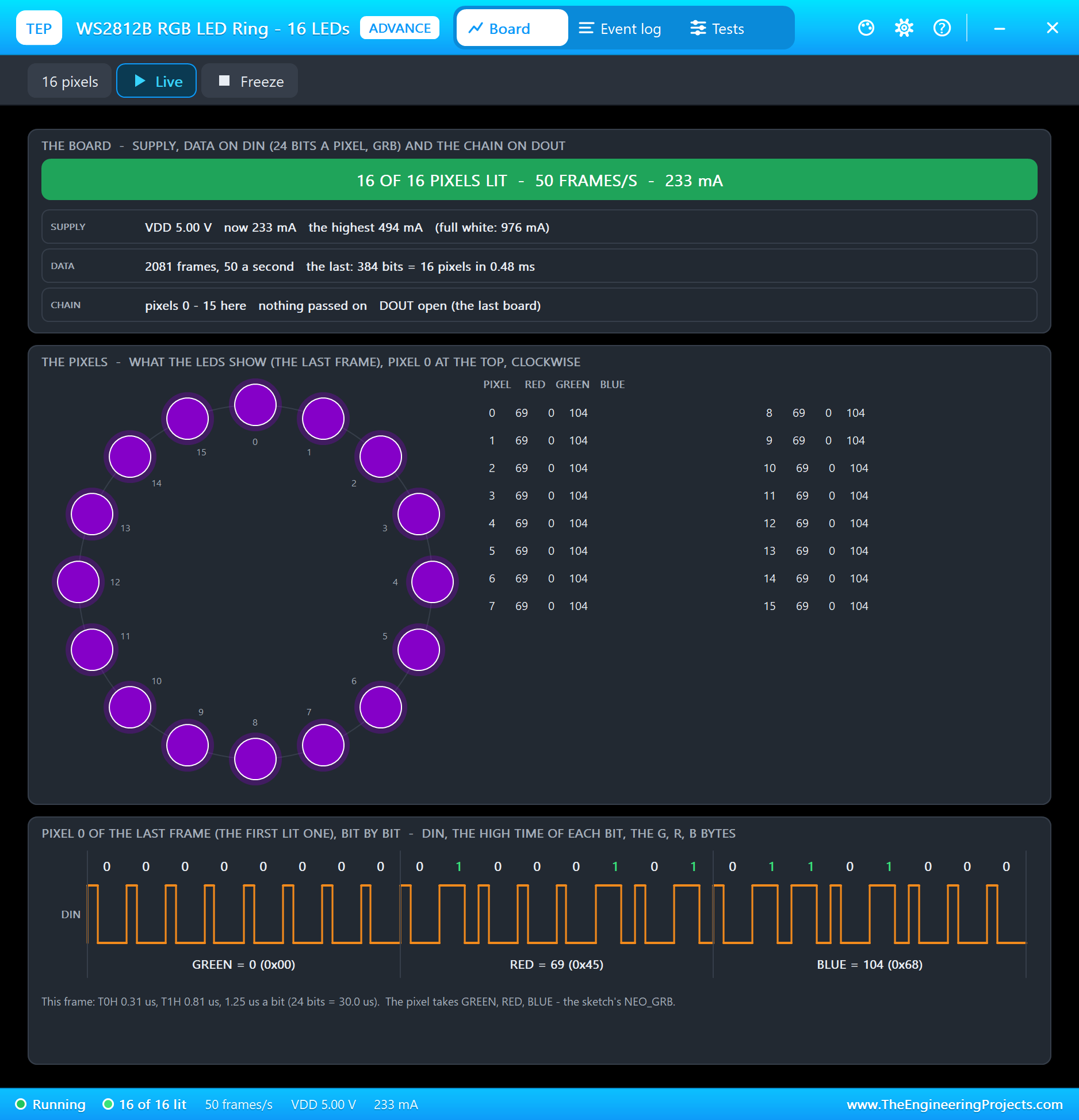
The ring's pop-up showed all 16 LEDs lit, 50 frames a second, each frame 384 bits for 16 pixels in 0.48 milliseconds, exactly the worked example above. It also measured the timing of the last frame: a 0 bit high for 0.31 microseconds, a 1 bit for 0.81, 1.25 microseconds a bit. The rainbow at half brightness drew 254 mA from the 5 V supply.
The Brightness from the Slider
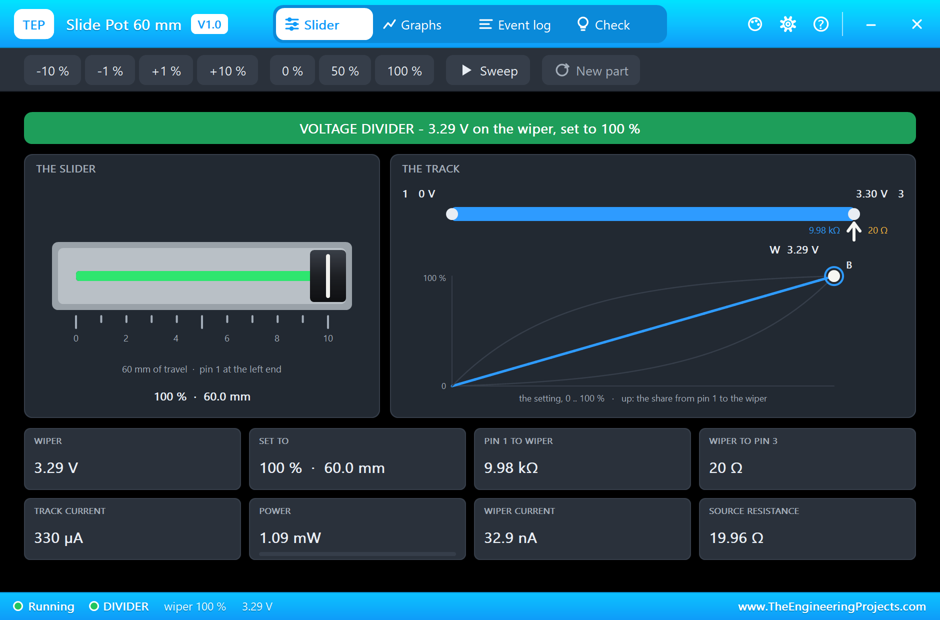
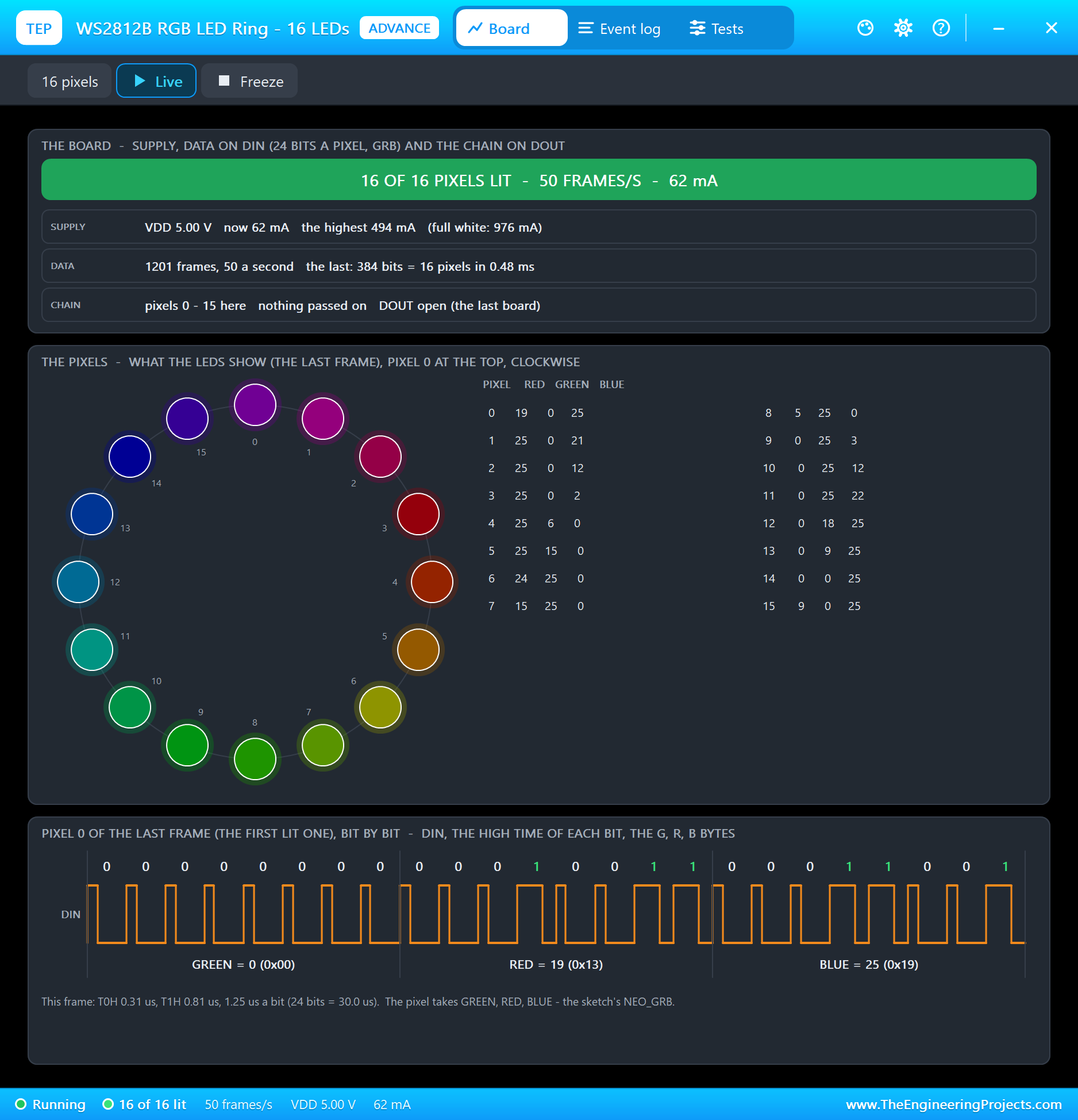
The slider to 100 percent in its pop-up: the ADC read 4,087 and the brightness became 99 percent; the rainbow at full brightness drew 493 mA. Then 0 percent and +10 percent: 416, a brightness of 9 percent and only 62 mA. The current follows the brightness almost in a straight line, because every LED's three colour channels are switched on and off by PWM inside the LED: half the duty, half the current. Back to 50 percent for the rest of the run.
The Button: FIRE and NIGHT
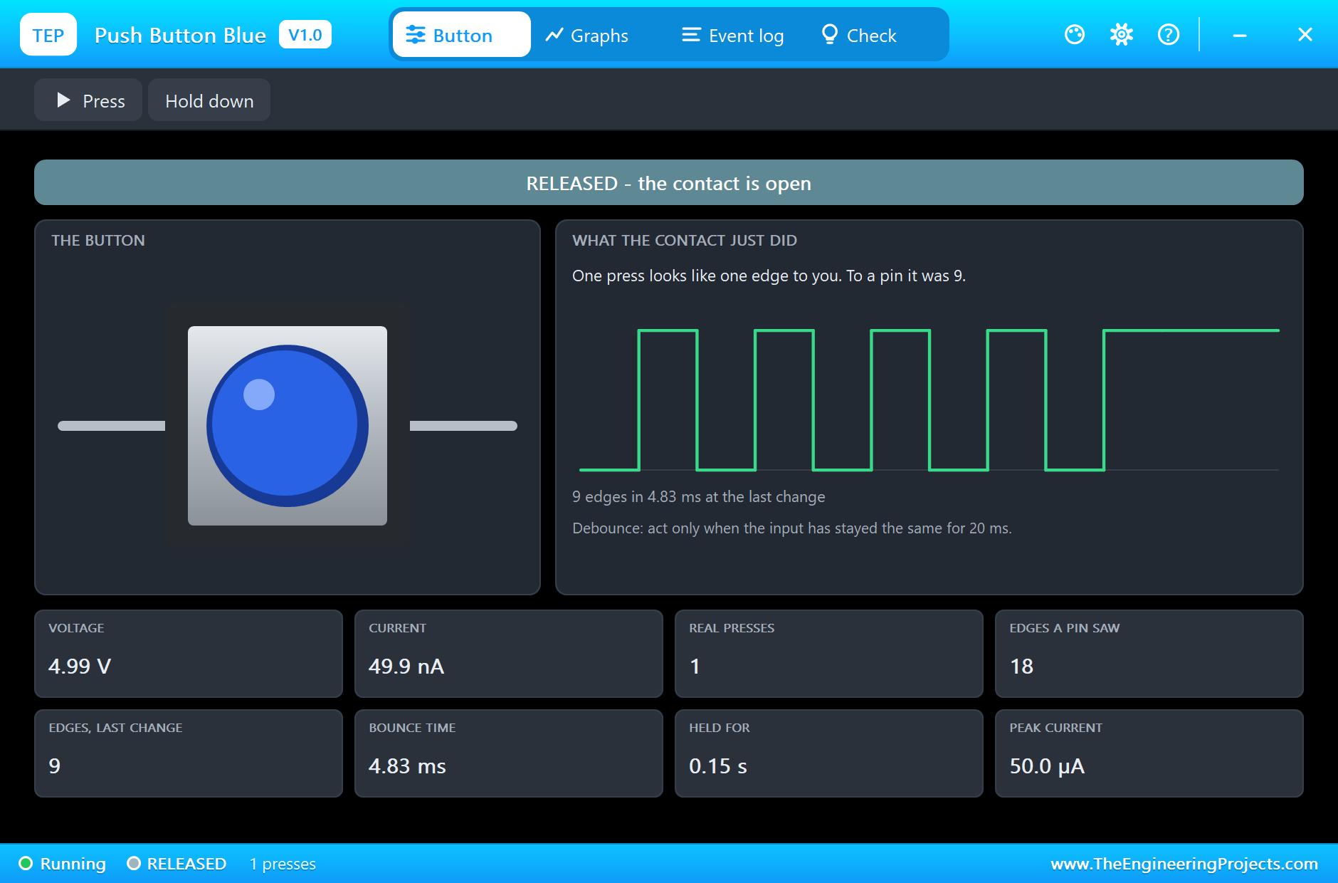
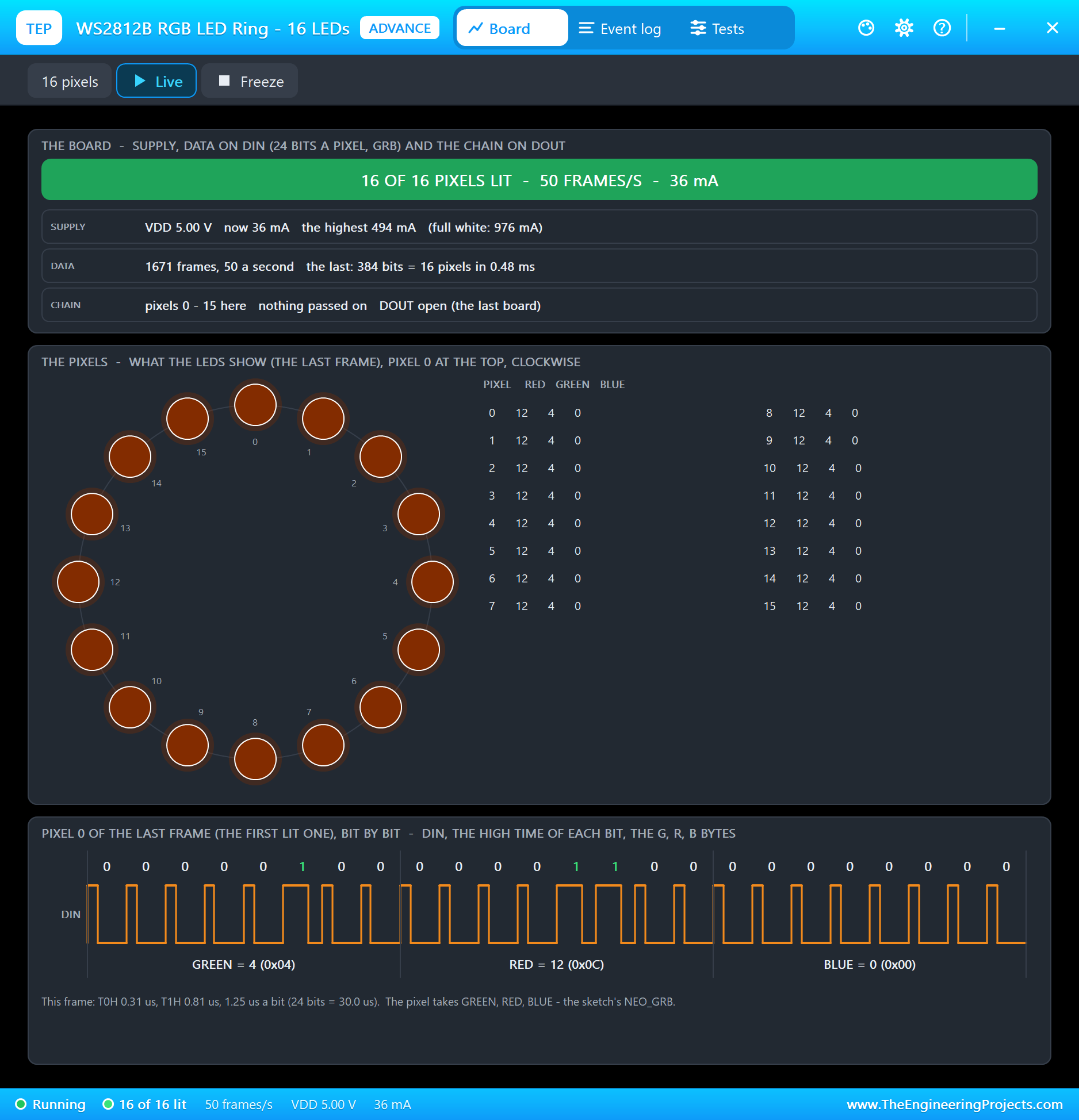
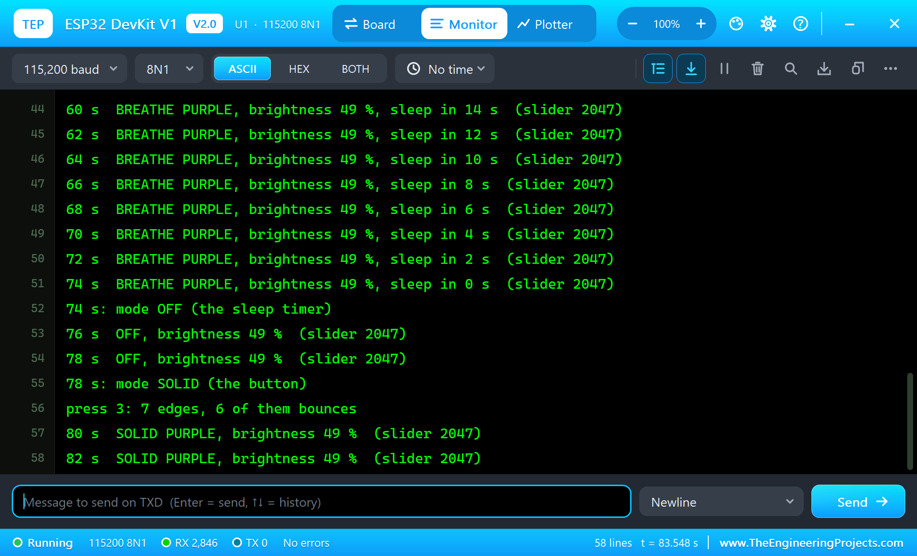
Press in the button's pop-up: at 26 seconds "mode FIRE (the button)", and the sketch reported "press 1: 9 edges, 8 of them bounces". The pop-up drew those edges: one press that a person feels as one click was 9 edges on the pin, all within 4.83 milliseconds, and 18 edges with the release. The sketch changed the mode once, because it waited until the pin had stayed the same for 30 milliseconds. The FIRE mode flickered every LED on its own between orange and red and drew 176 mA.
A second press at 31 seconds: "mode NIGHT", 5 edges this time, 4 of them bounces; the bounce is different at every press, as on a real switch. NIGHT is a warm glow at a tenth of the brightness: 36 mA.
Colours and Breathing from the Dashboard
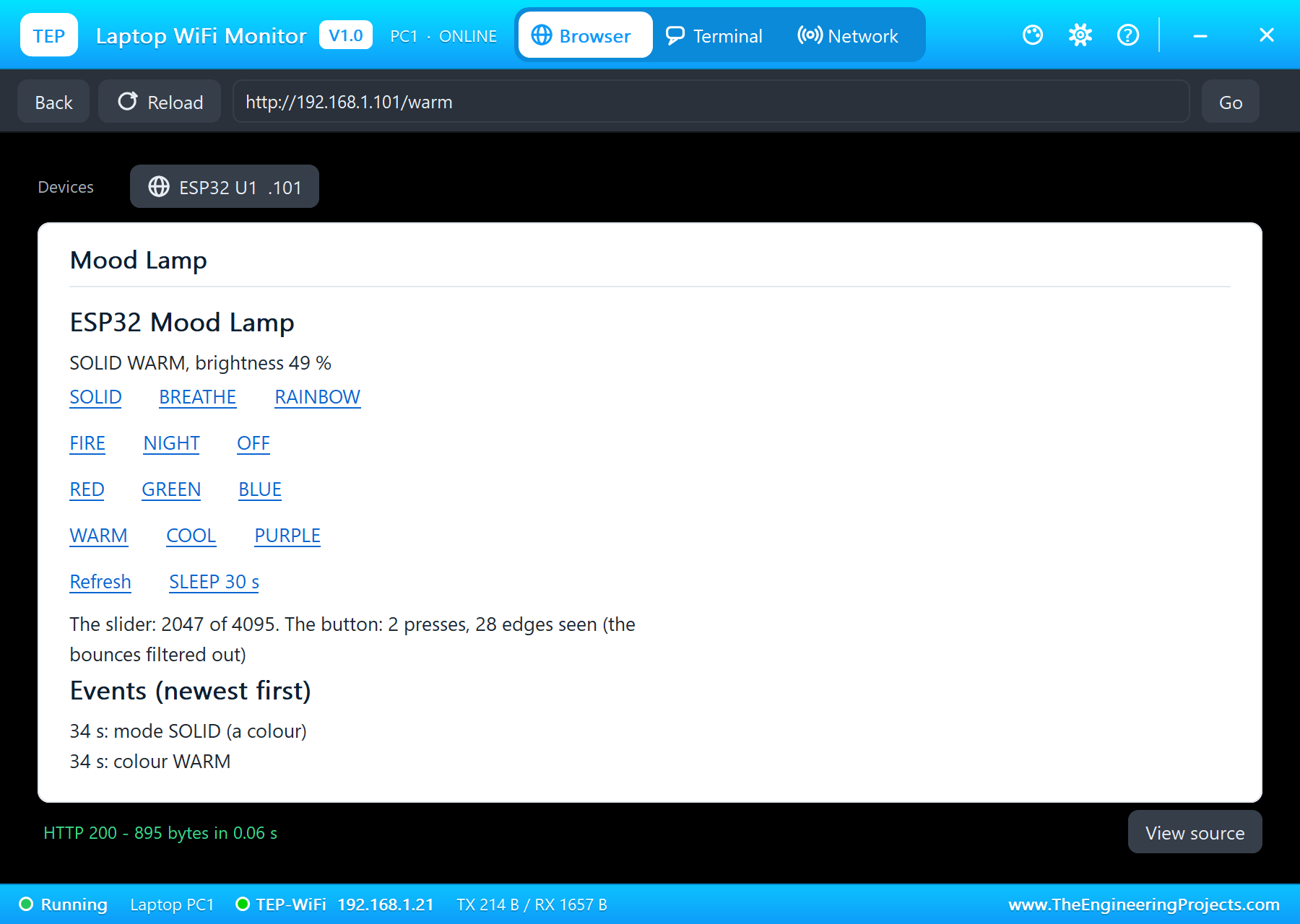
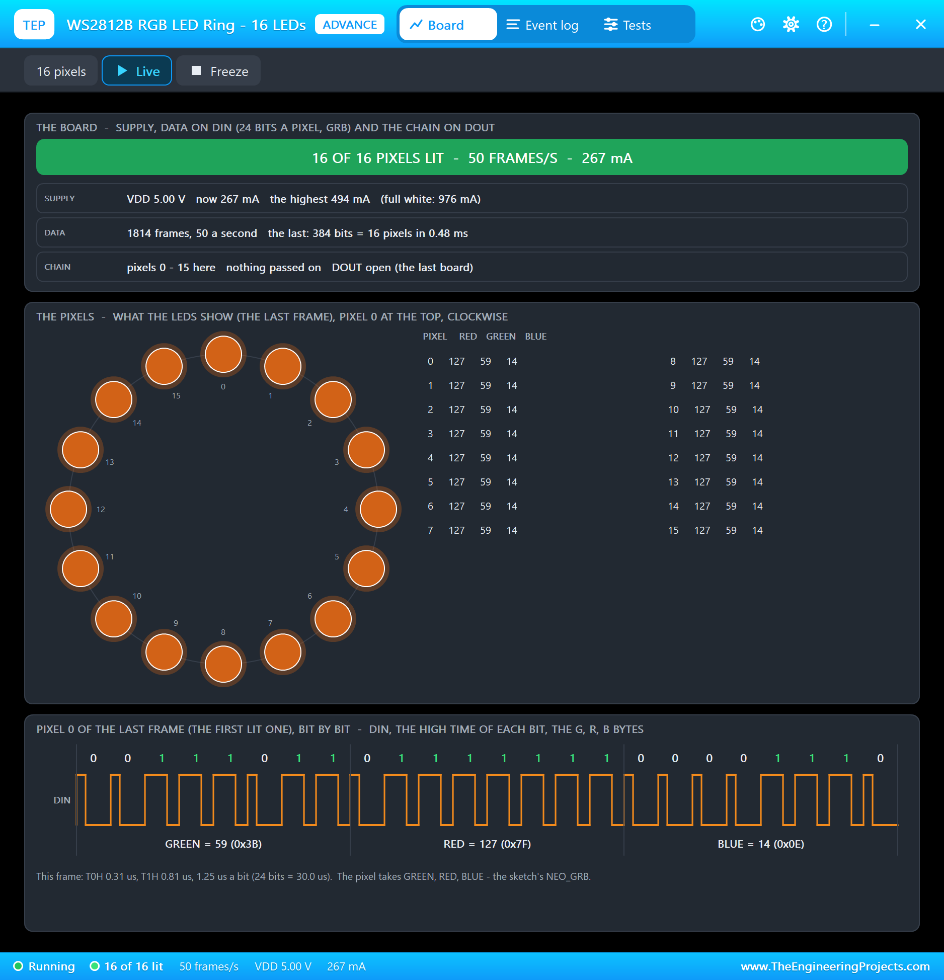
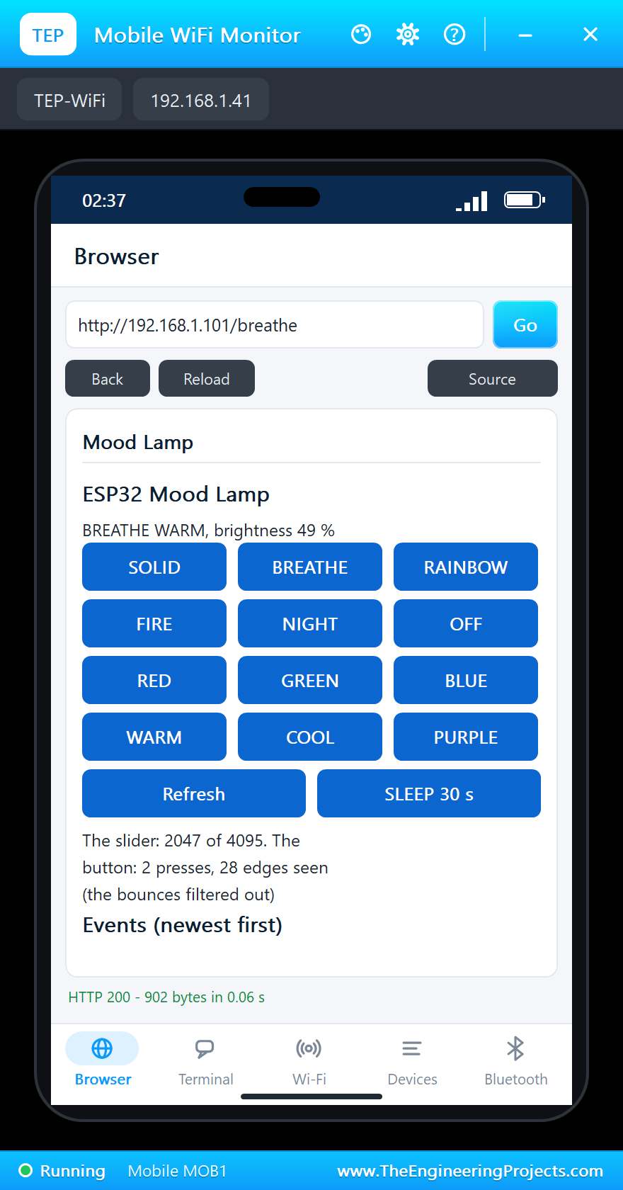
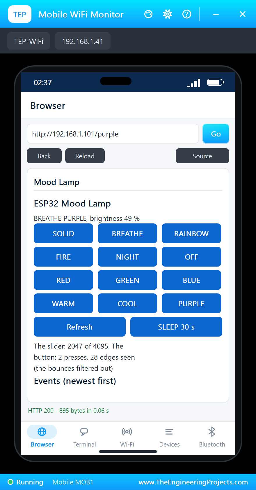
WARM on the laptop at 34 seconds: "colour WARM" and "mode SOLID (a colour)", all 16 LEDs warm white (red 255, green 120, blue 30, scaled to 49 percent), 267 mA. BREATHE on the phone at 36 seconds, then PURPLE at 38 seconds: the colour changed, the breathing went on. The pop-up caught one breath at 233 mA near its top and, 1.3 seconds later, at 93 mA near its bottom.
The Sleep Timer
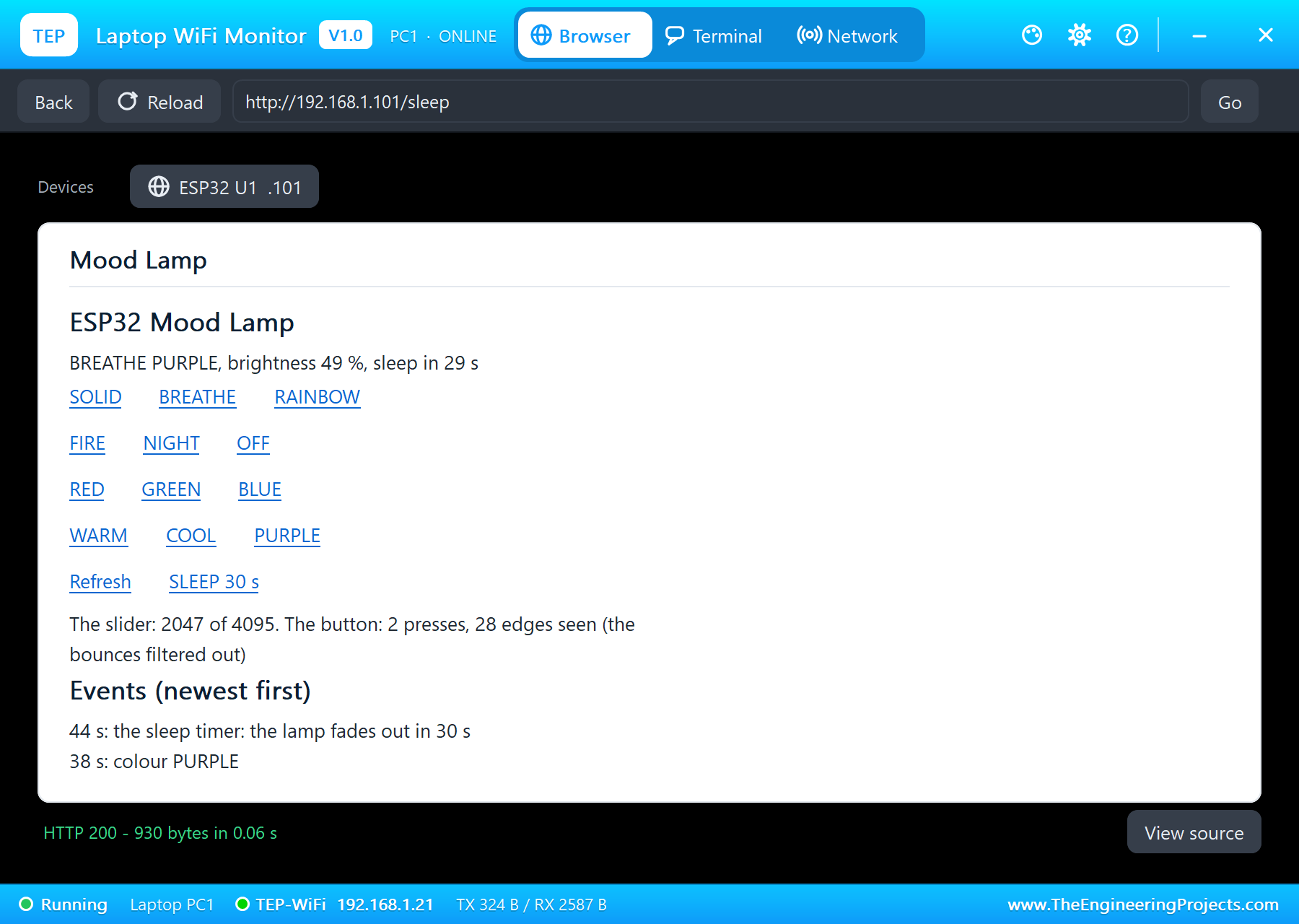
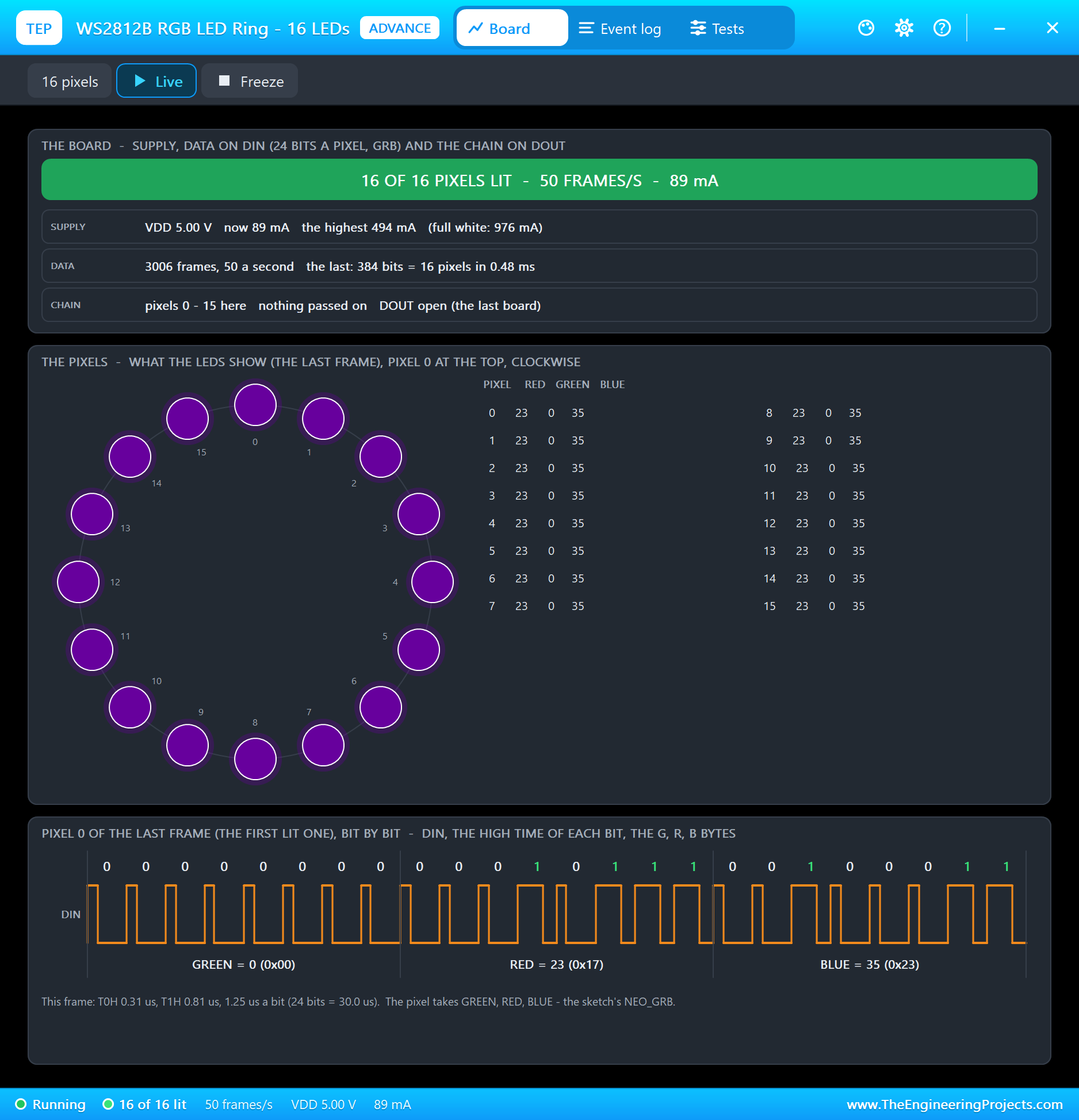
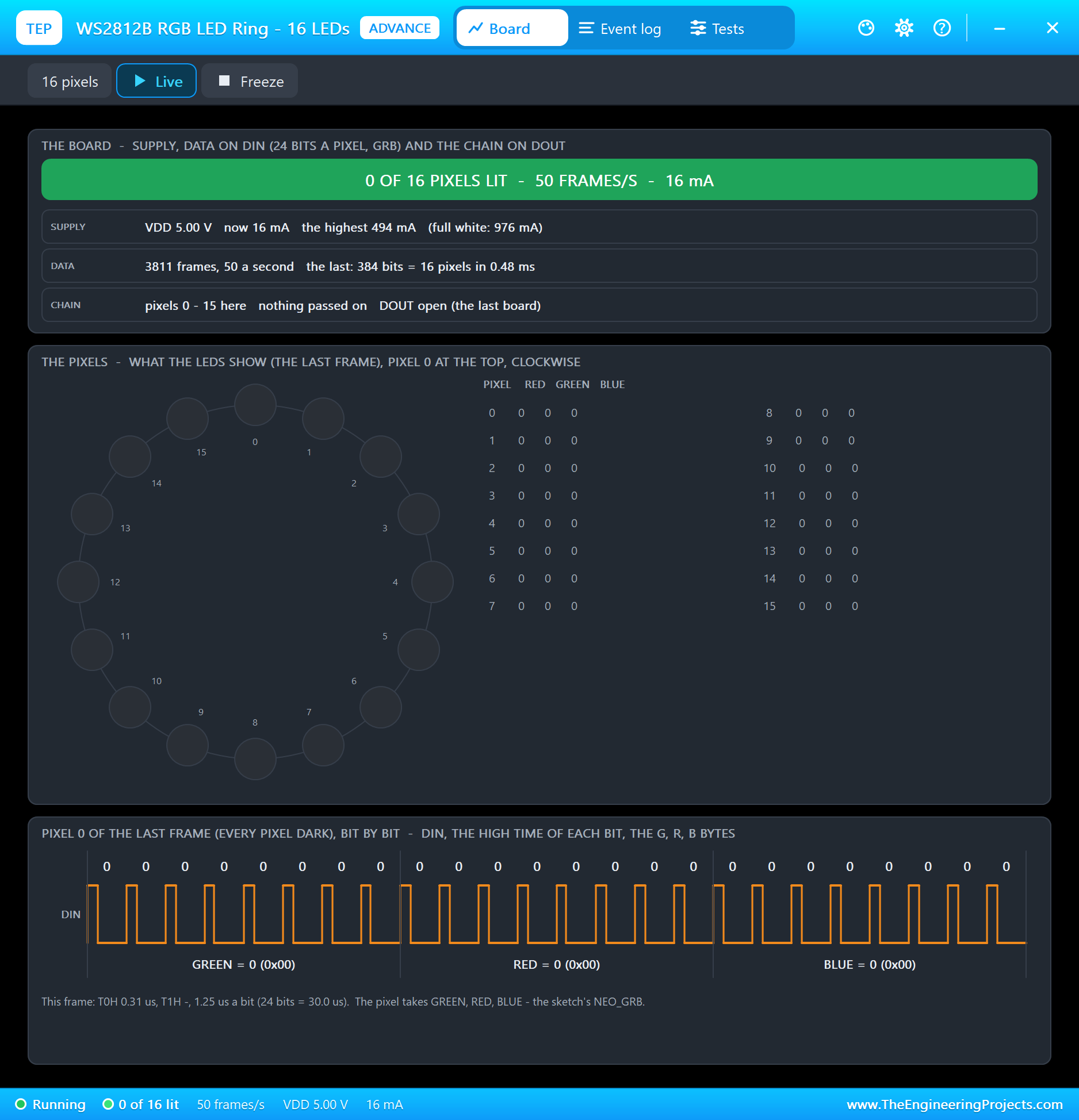
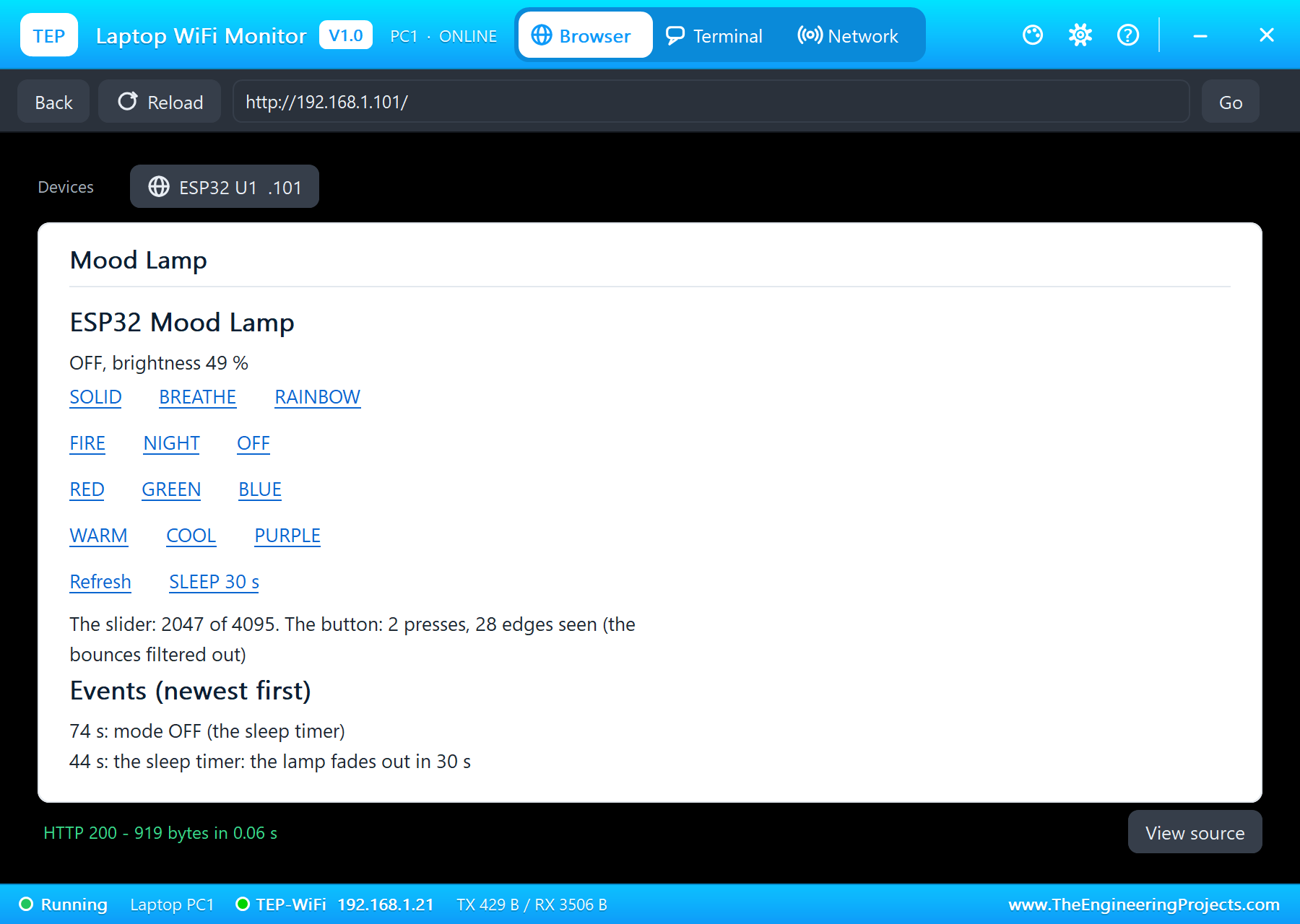
SLEEP 30 s on the laptop at 44 seconds: "the sleep timer: the lamp fades out in 30 s", and the dashboard counted down. Halfway the ring drew 89 mA, and at 74 seconds "mode OFF (the sleep timer)": 0 of 16 LEDs lit. The ring still drew 16 mA, the LEDs' own idle current of about 1 mA each, a point worth remembering for a battery lamp.
The Button Wakes It
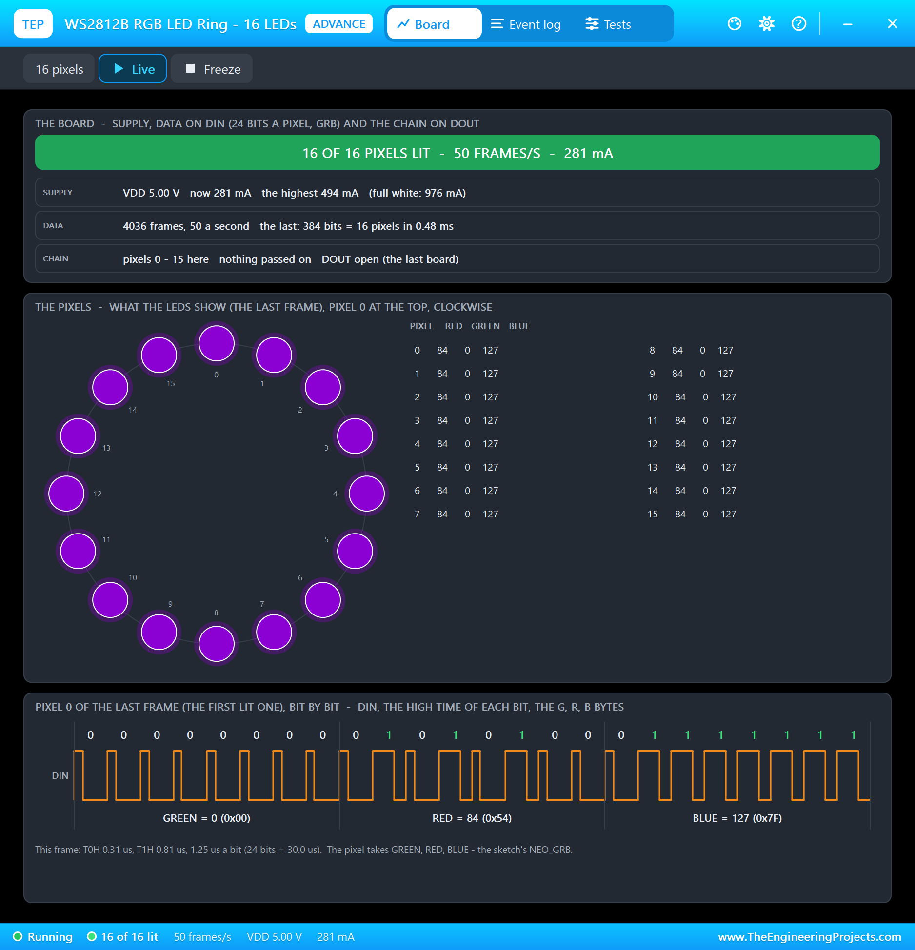
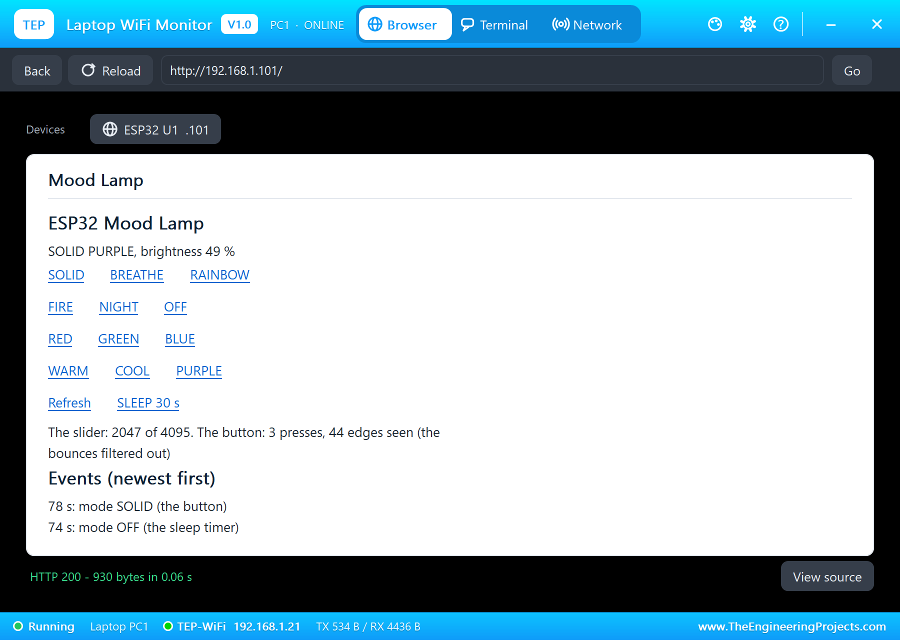
A third press at 78 seconds: "mode SOLID (the button)", 7 edges, 6 of them bounces, and the lamp came back in SOLID PURPLE, the colour it had last, at 281 mA. At the end of the run the ring had received 4,190 frames, the highest current had been 494 mA (full white would be 976 mA), and the button had made 52 edges for its 3 presses, every bounce filtered out. 84 seconds of simulation took about 6.5 minutes on our PC with all the captures.
Download the Project Files
Click the button below to download IoT-RGB-Mood-Lamp-ESP32-Proteus-Simulation-v1.0.zip (about 3.8 MB, without the source code of the models):
IoT RGB Mood Lamp with ESP32 - Proteus Simulation V1.0- Proteus Simulation: ESP32-RGB-Mood-Lamp.pdsprj, the compiled HEX file and copies of the models.
- Arduino Code: ESP32_RGB_Mood_Lamp.ino, the complete sketch.
- Proteus Library Files: the LIB files of the ESP32 DevKit V1, the WS2812B ring, the slide potentiometer, the push button and the two WiFi Monitors.
- Proteus Model Files: the DLL models.
- README.txt: the installation steps, the properties, the test results and the links to every library post.
No Proteus yet? Read How to Download and Install Proteus 7 and 8. New to libraries? Follow How to Install a New Library in Proteus.
How to Install the Project Files
- Close Proteus and extract the whole zip file, for example to your Desktop.
- Copy the files from Proteus Library Files into the LIBRARY folder of Proteus.
- Copy the files from Proteus Model Files into the MODELS folder.
- Start Proteus and open the project from the Proteus Simulation folder.
Changing the Code
Open the sketch in the Arduino IDE with the ESP32 boards and the Adafruit NeoPixel library installed, compile it, export the compiled binary and set the board's PROGRAM property to the new file. The modes and the colours are easy to extend: add a name to the lists and a case to the switch. The same sketch runs on a real ESP32 DevKit V1. For our other ESP32 home project, with an IR remote and relays, see the IoT Home Automation with ESP32 and IR Remote.
Ideas to Extend the Project
- Add a colour picker to the dashboard: three sliders for red, green and blue.
- Wake the lamp slowly in the morning: a sunrise mode that fades from red to warm white over 20 minutes.
- Add a microphone and make the ring pulse with music.
- Save the last mode and colour in the ESP32's flash, so the lamp starts as it was left.
- Chain a second ring on DOUT and make one long animation over both.
- Use a long press of the button for the sleep timer.
From Simulation to Real Hardware
- Give the LEDs their own supply: 16 LEDs can draw nearly 1 A at full white; a USB port may not deliver it.
- Add the classic protection: a 300 to 500 ohm resistor in the data line and a 1,000 microfarad capacitor across the ring's supply.
- Mind the logic level: the WS2812B expects at least 0.7 x VDD, 3.5 V at 5 V; a 3.3 V ESP32 pin usually works, but a level shifter such as a 74AHCT125 makes it certain.
- Keep the timing: the protocol needs exact pulse widths; on a real ESP32 the NeoPixel library uses the RMT peripheral, so Wi-Fi does not disturb it.
- Correct the brightness curve: the eye sees brightness logarithmically; a gamma table makes the slider feel even.
Troubleshooting
- The ring stays dark: DIN and DOUT swapped (the data goes into DIN), or no 5 V on the ring.
- The colours are wrong (red and green swapped): the ring is RGB, not GRB; change NEO_GRB to NEO_RGB.
- One press jumps two modes: the debounce time is too short for the switch; raise DEBOUNCE_MS.
- The brightness never reaches 0 or 100: the slider's ends are on the wrong rails; pin 1 to GND, pin 3 to 3.3 V.
- The dashboard does not open: the board is not on the network yet; wait for the Dashboard line in the serial monitor.
Limitations of the Simulation
- The light is shown on the ring's symbol and in its pop-up; it does not light the room.
- The supply in the simulation never sags, while a real USB port may fall short at full white.
- The network is simulated: the dashboard travels between the ESP32 and the two monitors inside Proteus; the times in this tutorial are simulation time.
- NeoPixel is a name used by Adafruit, and the ESP32 is made by Espressif; this project is not made or endorsed by them or by Labcenter.
So, that was all about the IoT RGB Mood Lamp with ESP32 - Proteus Simulation. I hope it helps you build your own: WS2812B LEDs on one data wire, colours on the HSV wheel, a slide potentiometer on the ADC, a debounced push button, six light effects and a fading sleep timer, all tested in a simulation before you solder a single LED. More IoT projects with the ESP32 and the Raspberry Pi 5 are coming in this series. If you have any questions, ask in the comments and I will help you out. Till the next tutorial, take care and have fun!

Comments
0