


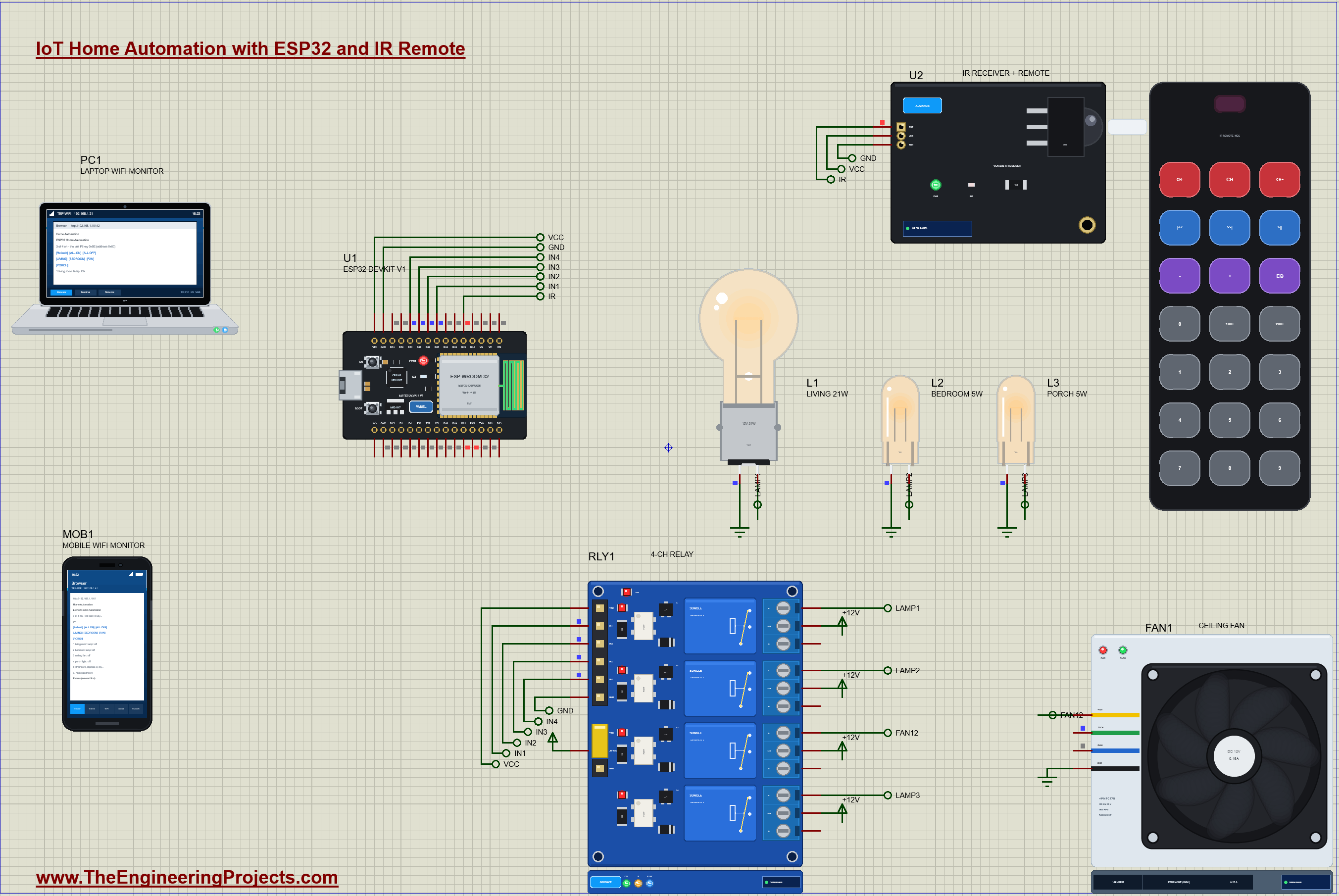
IoT Home Automation with ESP32 and IR Remote - Proteus Simulation


Hello friends, I hope you all are doing great. Today, I am going to share the IoT Home Automation with ESP32 and IR Remote - Proteus Simulation, the nineteenth project of our IoT Projects series. If you have searched for a Proteus simulation of home automation with an ESP32 and an IR remote, here is a complete one. An ESP32 decodes the frames of an ordinary 21-key infrared remote by itself and switches four loads of a room through a 4-channel relay module: a living room lamp, a bedroom lamp, a ceiling fan and a porch light. The same four switches are on a web dashboard for your laptop and your phone.
Home automation does not have to start with a smart speaker. Most homes already have a drawer full of IR remotes, and a cheap receiver lets a microcontroller understand them; add Wi-Fi and the same room answers a phone as well. In this tutorial, we will go through the circuit, learn how an IR remote sends a key as a train of 38 kHz bursts, decode the NEC protocol in the sketch without a library, check each frame so that noise cannot switch a load, drive a relay module whose inputs work backwards, walk through the code, and then run the simulation: keys, the web page, everything on and off, and a noisy lamp that breaks a frame. At the end, you can download the project with the code and every library file it needs.
NOTICE: Our team has put a lot of effort into this project: the circuit, the code and every part in the simulation are our own work, and you get them all free. Your feedback is the fuel that keeps us going, so please tell us what you think in the comments below. And if our free projects help you, you can buy us a coffee. So, let's get started with the IoT Home Automation with ESP32 and IR Remote - Proteus Simulation:
What Does This Home Automation System Do?
- An IR remote: keys 1 to 4 switch the living room lamp, the bedroom lamp, the ceiling fan and the porch light on or off; EQ switches everything on, 0 everything off.
- A web dashboard: the same four switches plus ALL ON and ALL OFF, the state of every load, the last key and the events.
- Safe decoding: every frame carries each byte twice, once inverted; a frame that does not add up is rejected, so noise cannot switch a lamp.
- One press, one switch: a key held down sends repeat codes, which are counted but switch nothing.
- Off at power-up: the relays stay off while the ESP32 starts, whatever the pins do.
It is a classic first home-automation project and a great way to learn a real-world protocol at the bit level. In the simulation, the remote's keys are in the IR receiver's pop-up, and a NOISE button stands for a fluorescent lamp or sunlight that disturbs the receiver.
Components Used in the Proteus Simulation
All the parts come from our Proteus libraries, each with its own tutorial. The project zip at the end includes every LIB and DLL file.
| Part | Proteus device | Library post | Connection |
|---|---|---|---|
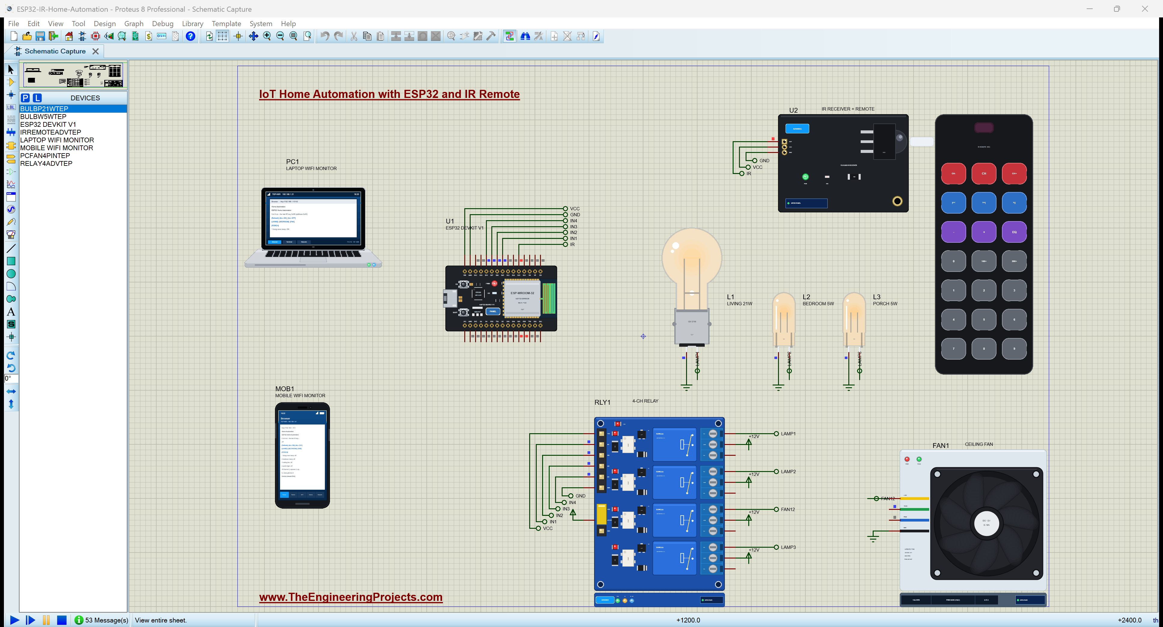
| ESP32 DevKit V1 | ESP32 DEVKIT V1 | ESP32 DevKit V1 Library for Proteus | U1, TEP-WiFi 192.168.1.101 |
| IR receiver + 21-key NEC remote | IRREMOTEADVTEP | IR Receiver + Remote Library for Proteus | U2, OUT on D35 |
| 4-channel 5 V relay module | RELAY4ADVTEP | Relay Module Library for Proteus | RLY1, IN1 - IN4 on D25, D26, D27, D14 |
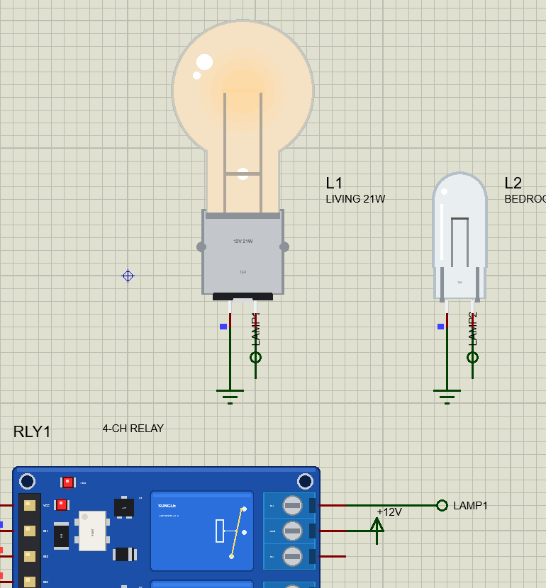
| 12 V 21 W lamp (living room) | BULBP21WTEP | Filament Bulb Library for Proteus | L1, on relay 1 |
| 12 V 5 W lamps (bedroom, porch) | BULBW5WTEP | Filament Bulb Library for Proteus | L2 on relay 2, L3 on relay 4 |
| 12 V fan (ceiling fan) | PCFAN4PINTEP | 4-Pin PC Fan Library for Proteus | FAN1, on relay 3 |
| Laptop WiFi Monitor | LAPTOP WIFI MONITOR | Laptop WiFi Monitor | PC1 |
| Mobile WiFi Monitor | MOBILE WIFI MONITOR | Mobile WiFi Monitor | MOB1 |
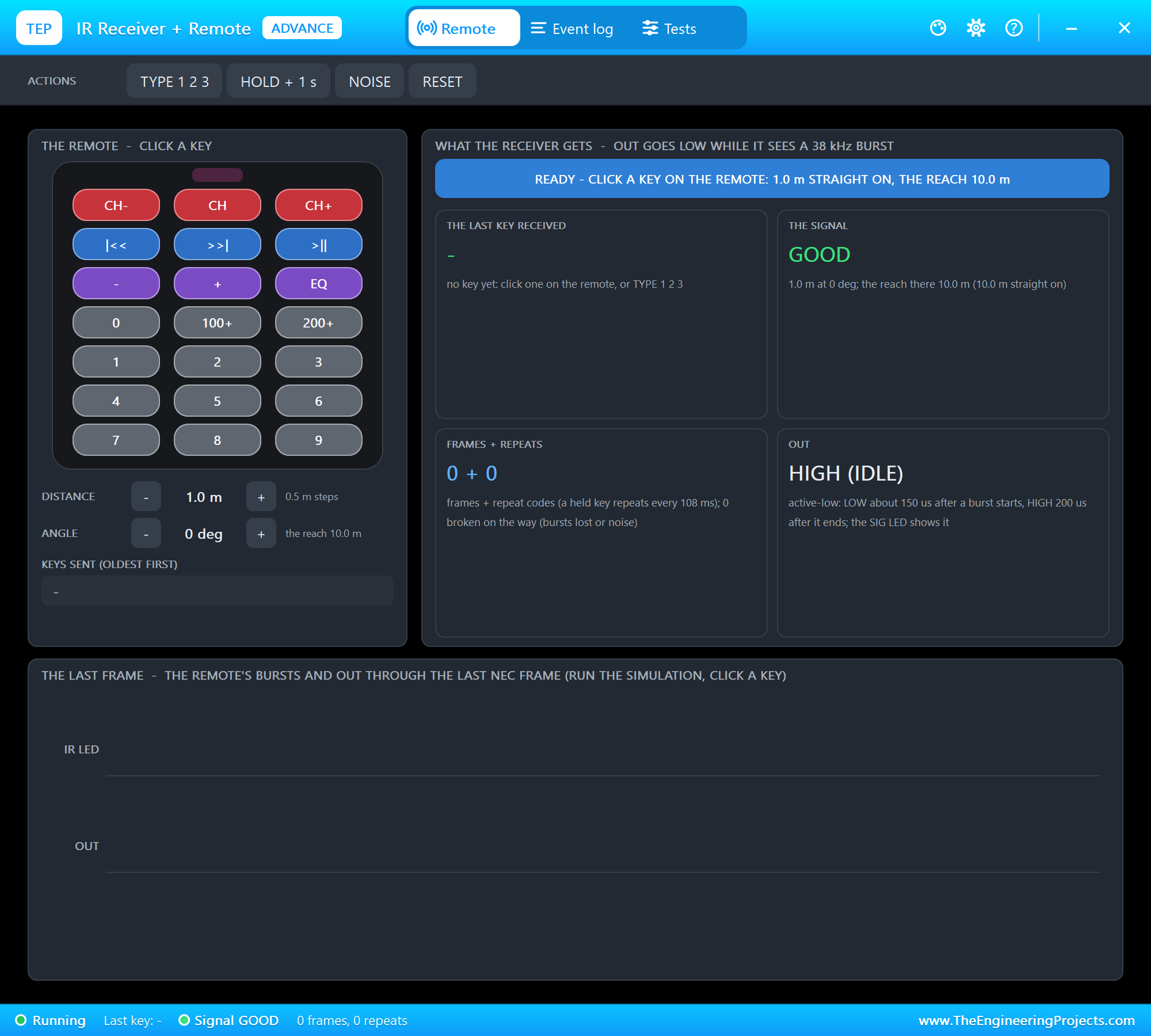
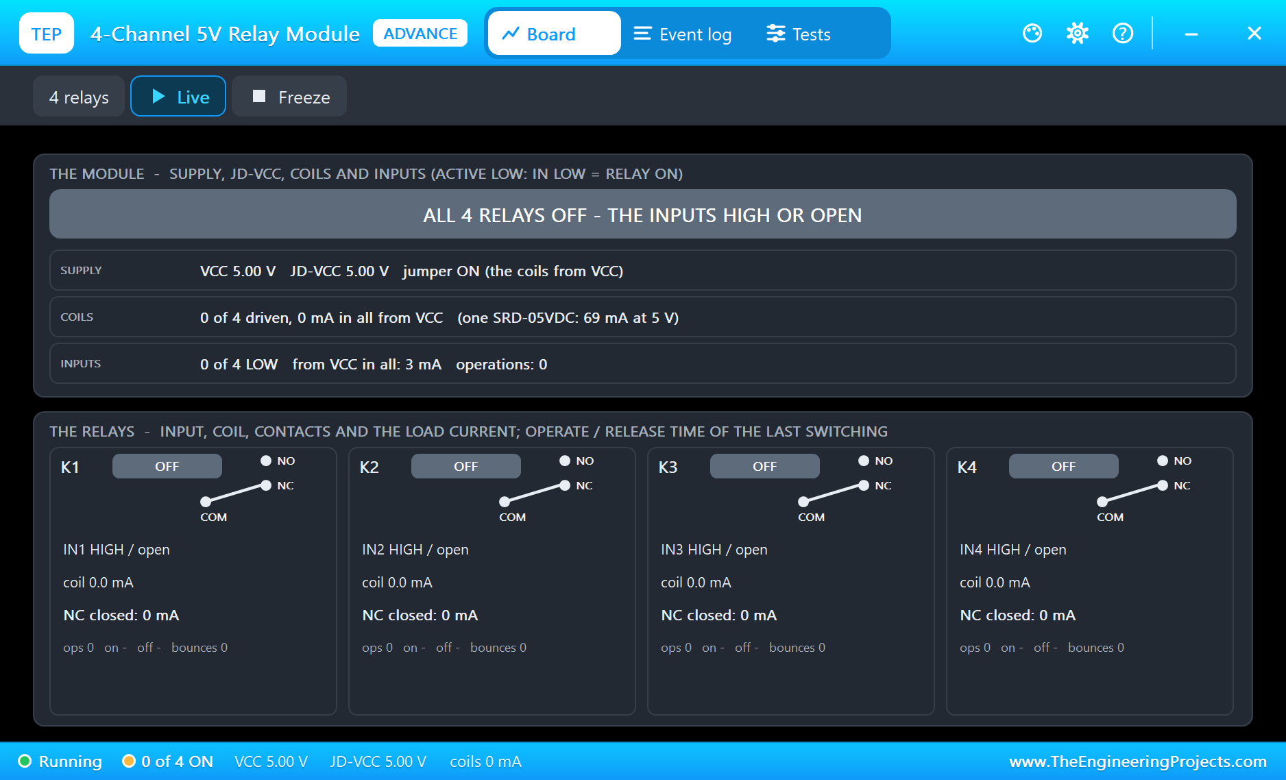
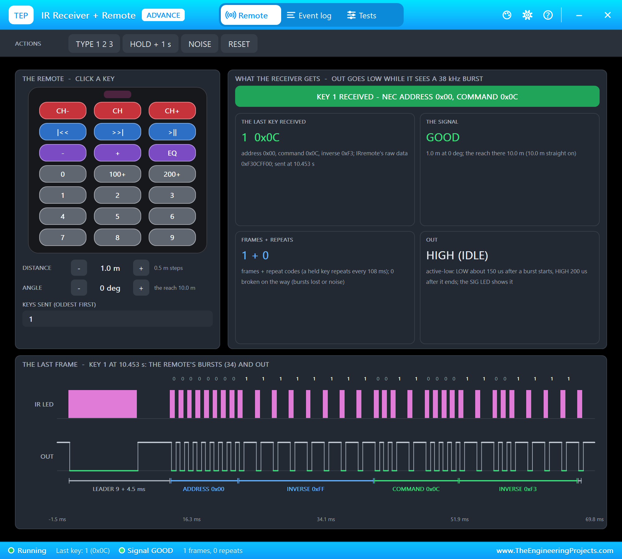
The IR receiver and the relay module are Advance models with pop-ups. The receiver's pop-up holds the remote: click a key and its NEC frame goes out; it also shows the last frame burst by burst, the signal and the frame and repeat counts, and sets the distance, the angle and noise. The relay module's pop-up shows each input, coil and contact and the current through it.
Proteus Simulation of the Home Automation System: the Circuit
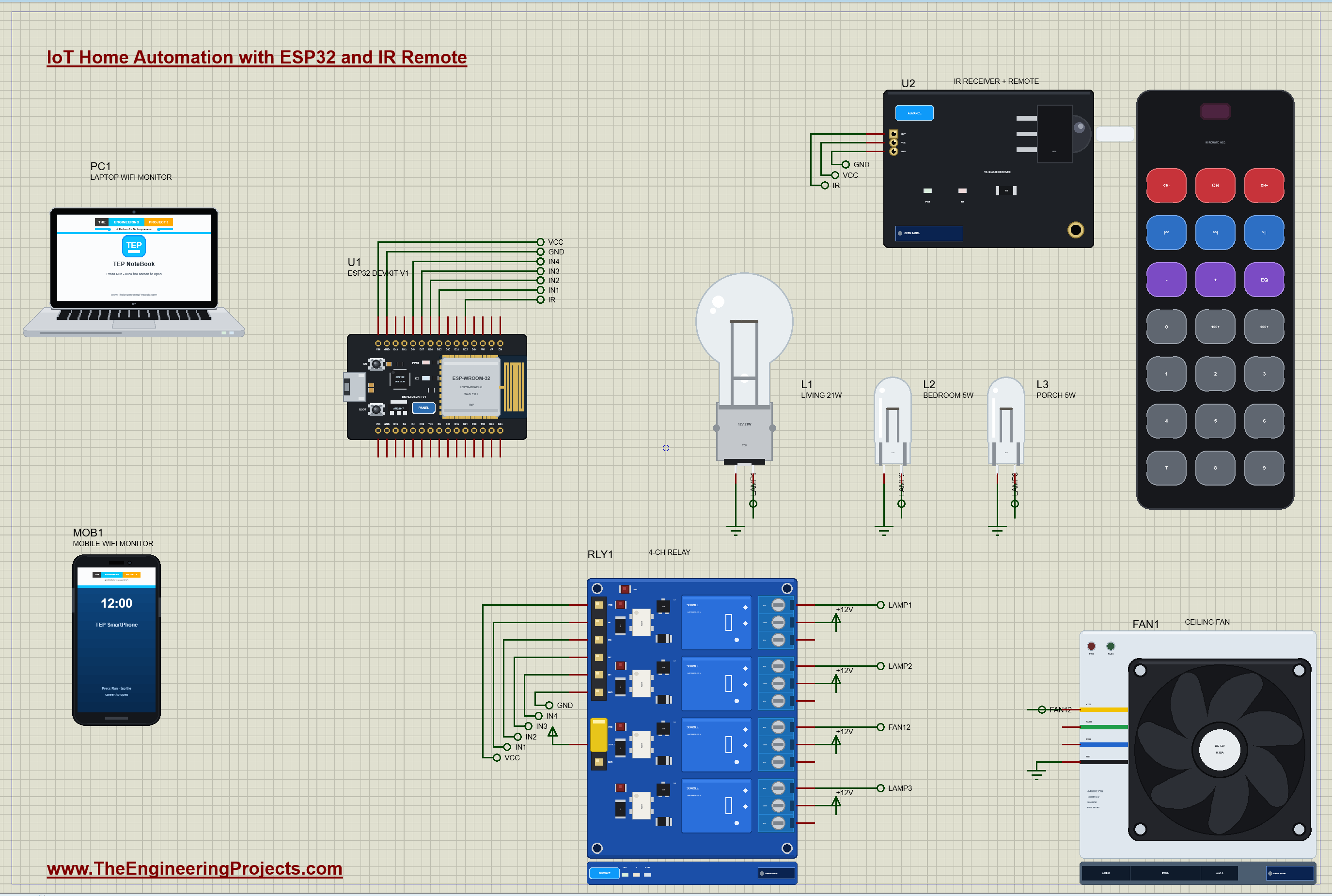
| Part | Pins | Connection |
|---|---|---|
| U2 IR receiver | OUT / VCC / GND | D35 / 5 V / GND |
| RLY1 relay module | IN1 / IN2 / IN3 / IN4 | D25 / D26 / D27 / D14 |
| RLY1 relay module | VCC and JD-VCC / GND | 5 V / GND |
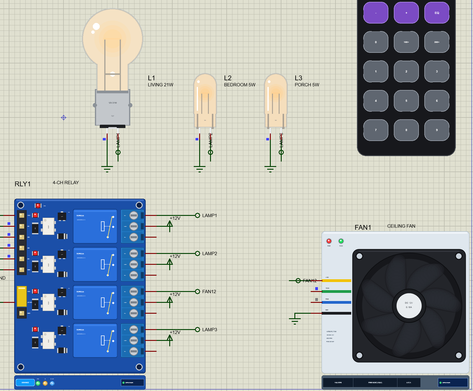
| Relays 1 - 4 | COM / NO | +12 V / the living lamp, the bedroom lamp, the fan, the porch light |
Each load is wired the way a light switch is: the relay's common contact goes to the 12 V supply, its normally open contact to the load, and the load's other side to ground. When the relay is off the load is off; a power cut leaves everything off. The fan's PWM and tach wires are left open, so it runs at full speed whenever relay 3 is on. D35 is an input-only pin of the ESP32, a good place for a receiver.
Supplies
The relay module and the IR receiver share the 5 V rail with the board's VIN pin; the module's JD-VCC pin supplies its coils, also from 5 V here. The loads run from a separate 12 V supply through the relay contacts, never through the ESP32. The receiver works from 2.7 to 5.5 V; on a real ESP32 you would power it from 3.3 V so that its output stays at the ESP32's logic level.
How the Home Automation System Works
Infrared and the 38 kHz Carrier
An IR remote flashes an infrared LED, but not simply on and off: each "on" is a burst of 38,000 flashes a second. The receiver module has a photodiode, an amplifier and a band-pass filter tuned to 38 kHz, so sunlight and lamps, which do not flicker at 38 kHz, are mostly ignored. Its output is active-low: OUT goes LOW while it sees a burst and HIGH in between. The sketch only ever sees those LOW and HIGH times.
The NEC Protocol
Most cheap remotes, including this kit's, speak the NEC protocol. A frame starts with a 9 ms burst and a 4.5 ms space, the leader. Then come 32 bits, least significant first: the address, the address inverted, the command and the command inverted. Every bit starts with a 562.5 microsecond burst; a short space of 562.5 microseconds after it means 0, a long one of 1687.5 microseconds means 1. A final burst ends the frame. While a key stays down the remote does not repeat the frame; it sends a short repeat code (a 9 ms burst and a 2.25 ms space) every 108 ms.
| Part of the frame | Burst | Space | Meaning |
|---|---|---|---|
| leader | 9 ms | 4.5 ms | a new frame |
| repeat code | 9 ms | 2.25 ms | the key is still down |
| bit 0 | 562.5 us | 562.5 us | 0 |
| bit 1 | 562.5 us | 1687.5 us | 1 |
Worked example: key 1 sends address 0x00 and command 0x0C. The four bytes are 0x00, 0xFF (0x00 inverted), 0x0C and 0xF3 (0x0C inverted); read LSB first as one 32-bit number, that is 0xF30CFF00. Because every byte comes with its inverse, each frame has exactly 16 ones and 16 zeros: 16 x 1.125 ms + 16 x 2.25 ms = 54 ms of bits, plus 13.5 ms of leader and the final burst, 67.5 ms for every key.
Checking Every Frame
The inverted copies are the protocol's checksum. The sketch XORs each byte with its inverse; the result must be 0xFF for the address and for the command, or the frame is thrown away. A single burst lost to noise or distance turns a 1 into a 0 or the other way round, and then the two copies no longer match. It also gives up on any burst or space that lasts far too long. That is what makes a cheap receiver safe enough to switch mains loads in a real home.
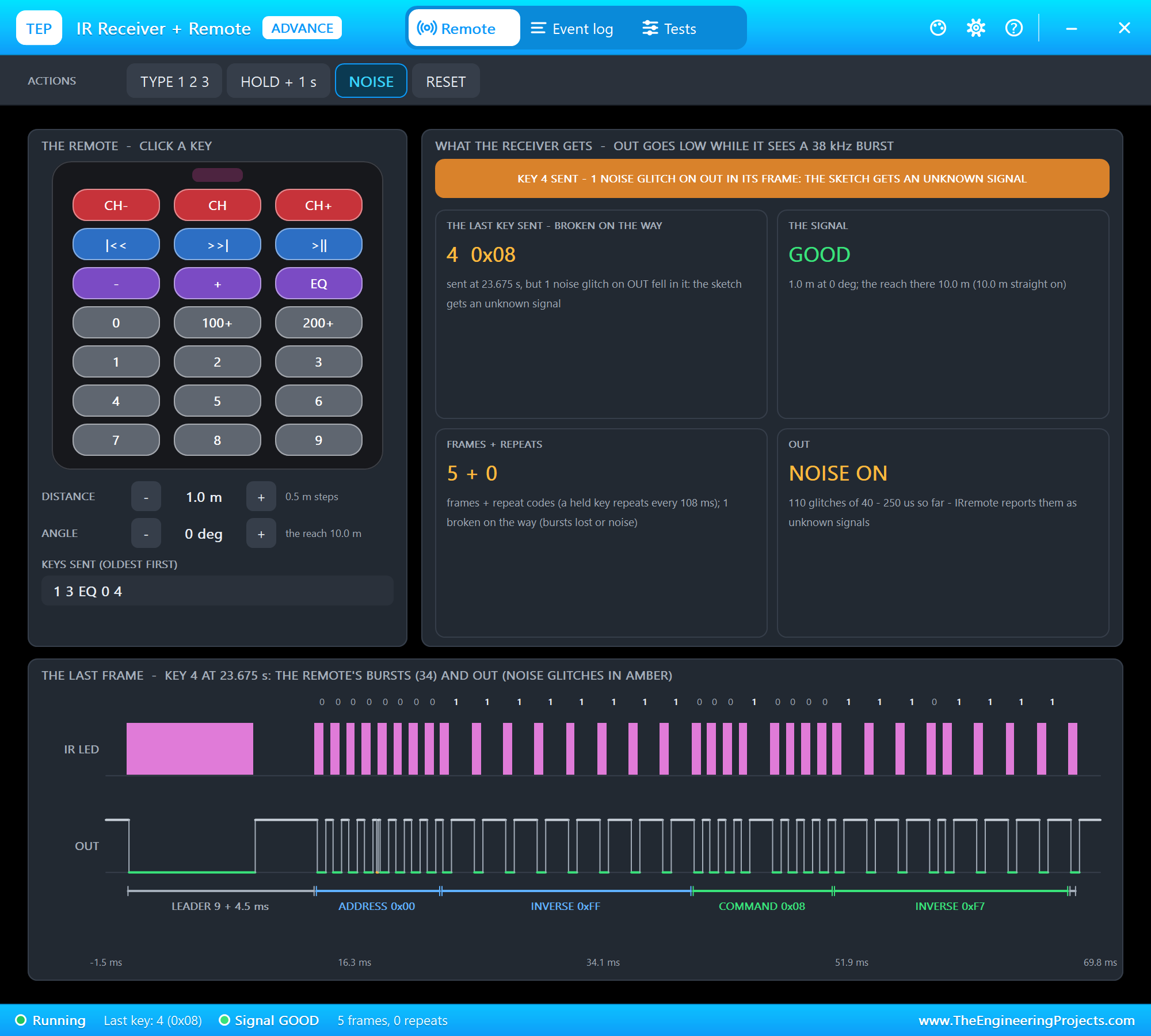
Noise needs one more rule. A fluorescent lamp or sunlight makes the receiver's output dip LOW for a fraction of a millisecond, many times a second. Each dip looks like the start of a frame, and our first test run logged dozens of "rejected" frames in two seconds that were nothing but noise. A real leader is a 9 ms burst, so a LOW that ends within 2 ms cannot be one: the sketch now counts it as a glitch without a word, and logs a broken frame at most once every 2 seconds.
The Keys
| Key | NEC command | What it does |
|---|---|---|
| 1 | 0x0C | the living room lamp on / off |
| 2 | 0x18 | the bedroom lamp on / off |
| 3 | 0x5E | the ceiling fan on / off |
| 4 | 0x08 | the porch light on / off |
| EQ | 0x09 | everything on |
| 0 | 0x16 | everything off |
Why not act on the repeat codes? A lamp switch must toggle exactly once per press. If the sketch acted on repeat codes, a key held for half a second would send four of them and switch the lamp on, off, on and off again. Repeats are useful for keys that step a level, such as volume or dimming: there, each repeat would move the level one step, which is one of the ideas at the end of this tutorial.
Relays That Work Backwards
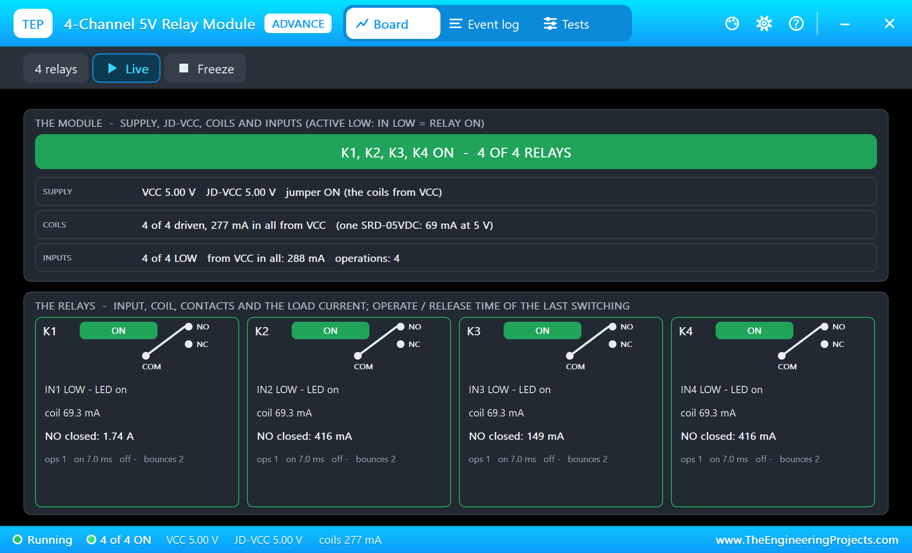
A relay module's input drives the LED of an optocoupler that sits between the module's VCC and the IN pin, so current flows, and the relay switches on, when IN is LOW. That is why the sketch writes LOW for "on" and HIGH for "off", and why it sets every relay pin HIGH before it makes it an output: otherwise each relay would click on for a moment at power-up. The contacts carry the loads: the 21 W lamp draws 21 / 12 = 1.75 A, a 5 W lamp 0.42 A, the fan about 0.15 A, all well inside a 10 A relay contact.
The ESP32 Code Explained
The whole sketch is included in the download. It uses only the WiFi and WebServer libraries of the ESP32 core; the NEC decoder is about thirty lines of its own. At the top are the pins and the remote's commands:
const byte KEY_LOAD[4] = {0x0C, 0x18, 0x5E, 0x08};Timing the Bursts and the Spaces
Two small helpers measure how long OUT stays LOW or HIGH, with a limit so that a broken frame cannot hang the sketch:
while (digitalRead(IR_PIN) == LOW) if (micros() - t > limit) return -1;A LOW far shorter than the leader is noise:
if (lead < 2000) return 3; // far too short for a leader: a glitch (a lamp, sunlight), not a frameThe space after the leader tells a frame from a repeat code, and the space after each bit's burst tells a 0 from a 1:
long space = highFor(6000); // 4.5 ms = a frame, 2.25 ms = a repeat code if (s > 1100) data |= 1UL << i; // 562.5 us = 0, 1687.5 us = 1And the check with the inverted copies:
return (addr ^ naddr) == 0xFF && (cmd ^ ncmd) == 0xFF ? 1 : 0; // each byte is followed by its inverse if (r == 2) { repeats++; return; } // (a key held down: we switch once per press)The Main Loop
The loop watches OUT; the moment it goes LOW, the leader of a frame has begun, and the decoder takes over for the 67.5 ms of the frame. The leader's 9 ms burst is long enough for the loop to catch it between web requests:
if (digitalRead(IR_PIN) == LOW) handleIr(); // a burst: the start of a frame (polled often enough to catch the 9 ms leader)The Relays and the Page
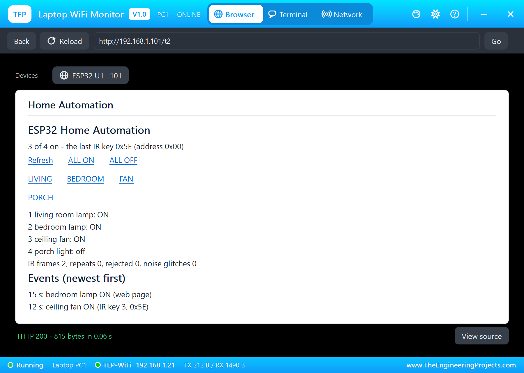
digitalWrite(RELAY[i], state ? LOW : HIGH); // the module's inputs are active LOW for (byte i = 0; i < 4; i++) { digitalWrite(RELAY[i], HIGH); pinMode(RELAY[i], OUTPUT); } // HIGH first: all off at power-up if (cmd == KEY_EQ) { setAll(true, "IR key EQ, 0x09"); return; } server.on("/t1", []() { toggle(0); });The pages are / (the dashboard), /t1 to /t4 (switch one load), /on, /off and /data (JSON). Every switch, from the remote or from the page, is logged as an event with who did it.
How to Run the Proteus Simulation
- Download the project zip below and install the library files (the steps are under the download button).
- Open ESP32-IR-Home-Automation.pdsprj from the Proteus Simulation folder. Keep the .hex and DLL files next to it.
- Press Play. The ESP32 joins TEP-WiFi and everything is off.
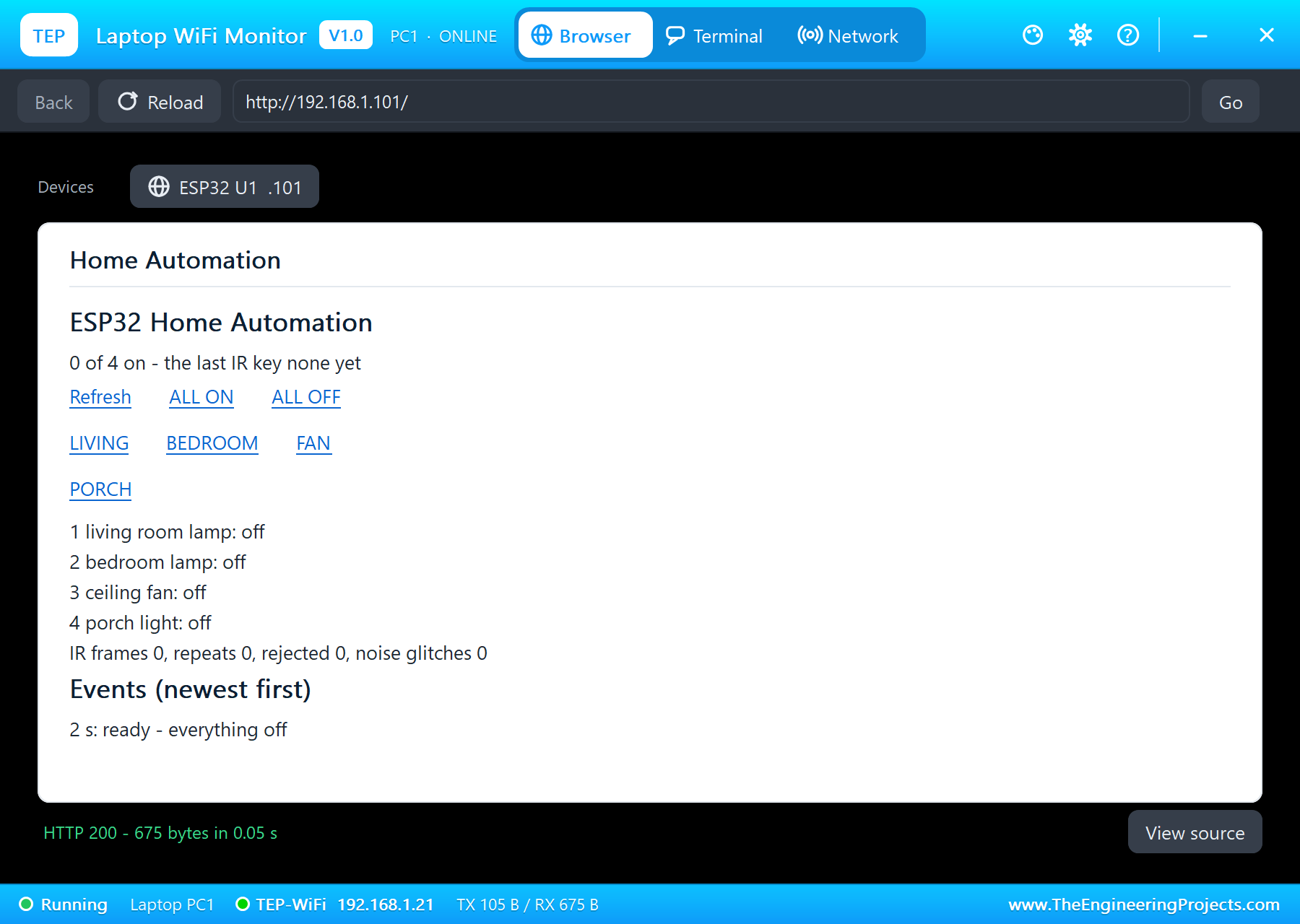
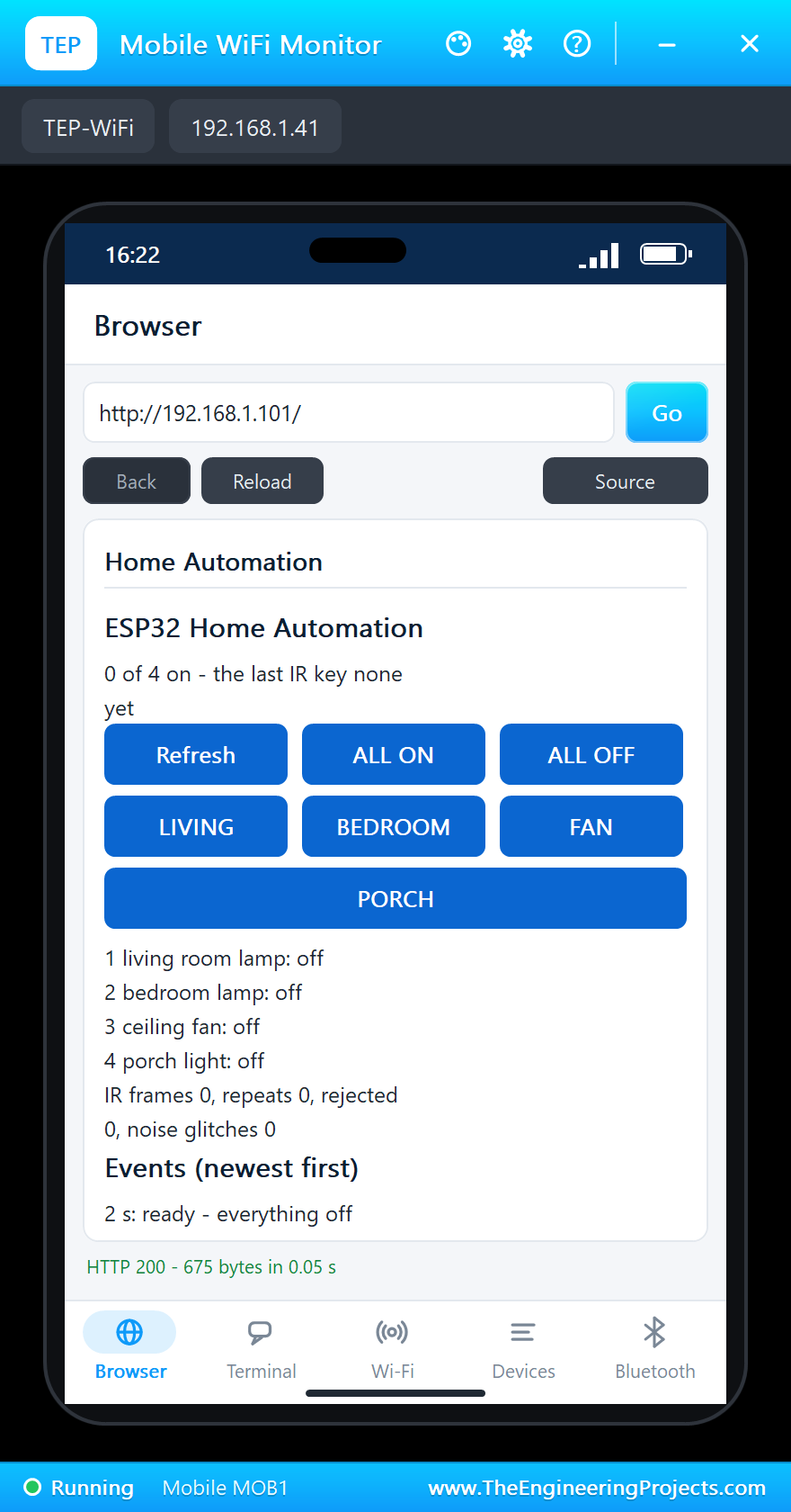
- Open the Laptop WiFi Monitor (PC1) or the Mobile WiFi Monitor (MOB1) and press Go.
- In the IR receiver's pop-up (U2) click key 1: the living room lamp lights. Try 2, 3, 4, EQ and 0.
- Switch the loads from the page too, and try NOISE in the pop-up before a key.
Proteus Simulation Results
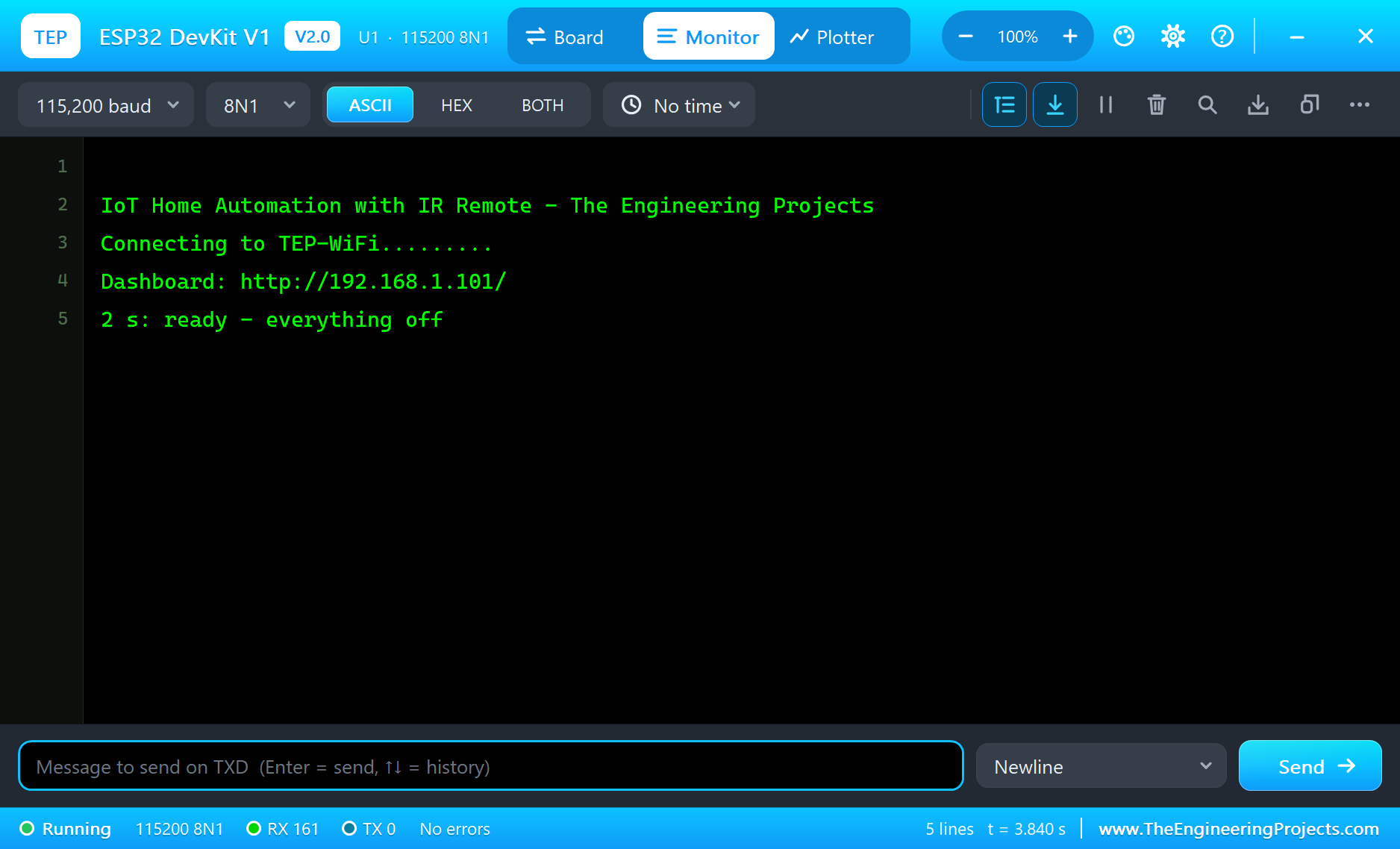
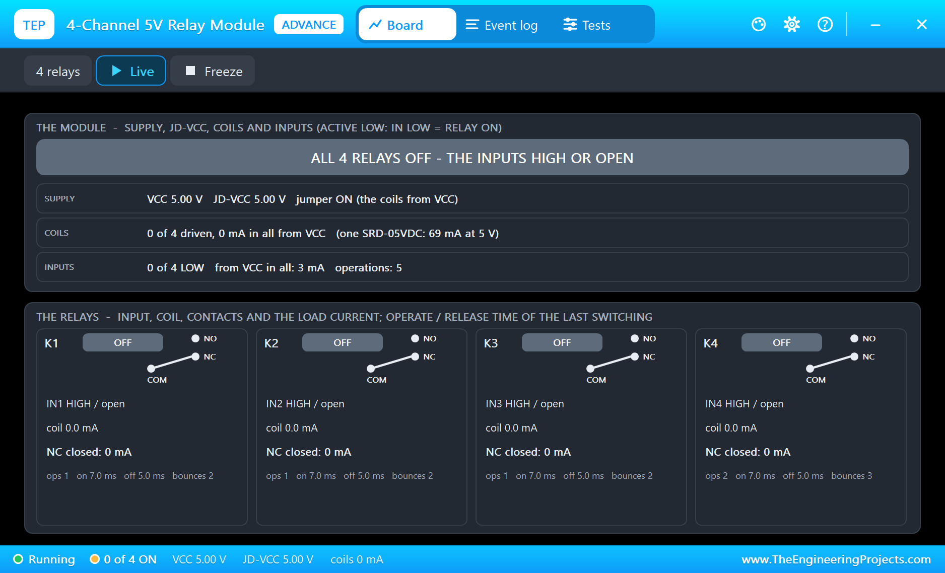
Here is one complete run of the simulation, with the numbers from our final test run; the times are simulation seconds since the ESP32 started. The serial monitor shows the start: the dashboard at http://192.168.1.101/ and "ready - everything off" at 2 seconds. The relay module's pop-up shows all four inputs HIGH and all four relays off, exactly as the sketch set them before it made the pins outputs.
Keys and the Web Page
First, key 1 on the remote. The receiver's pop-up drew the frame burst by burst: the 9 ms + 4.5 ms leader, then address 0x00, its inverse 0xFF, command 0x0C and its inverse 0xF3, IRremote's raw data 0xF30CFF00, the very number of the worked example. The sketch decoded the same frame, and at 10 seconds it logged "living room lamp ON (IR key 1, 0x0C)"; relay 1 closed and the 21 W lamp lit.
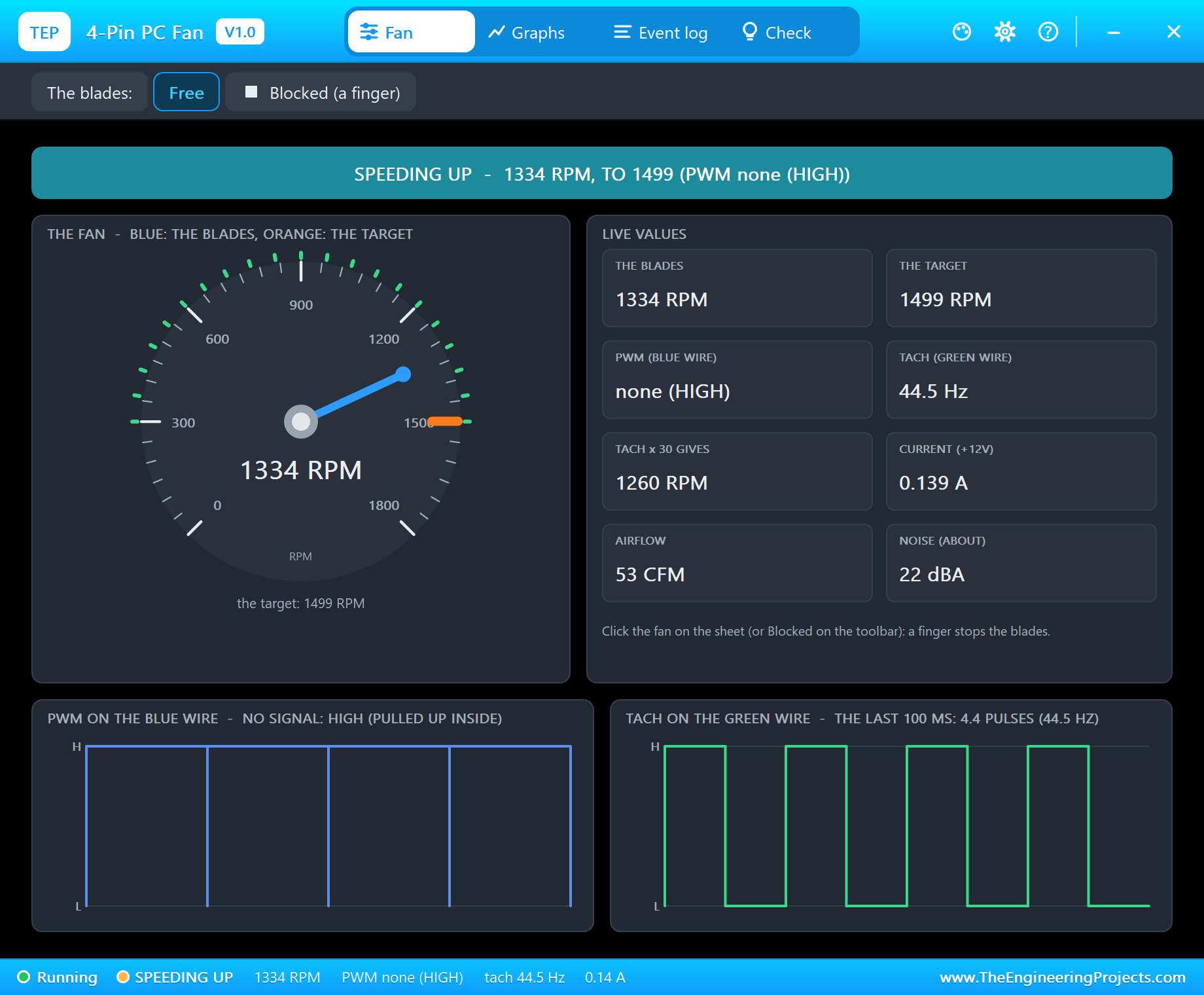
Key 3 at 12 seconds: "ceiling fan ON (IR key 3, 0x5E)", and the fan spun up to full speed, its PWM wire open. Then BEDROOM on the laptop: "bedroom lamp ON (web page)" at 15 seconds. The page and the remote switch the same loads, and each event says who switched it.
Everything On, Everything Off
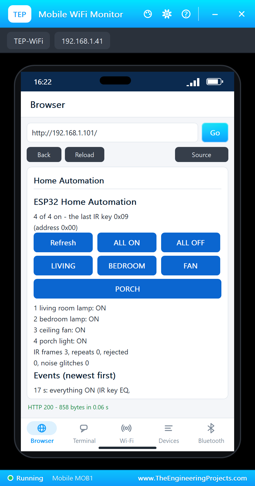
EQ at 17 seconds: "everything ON (IR key EQ, 0x09)". All four relays closed: the two lamps, the porch light and the fan. Key 0 at 22 seconds switched everything off again.
A Noisy Lamp
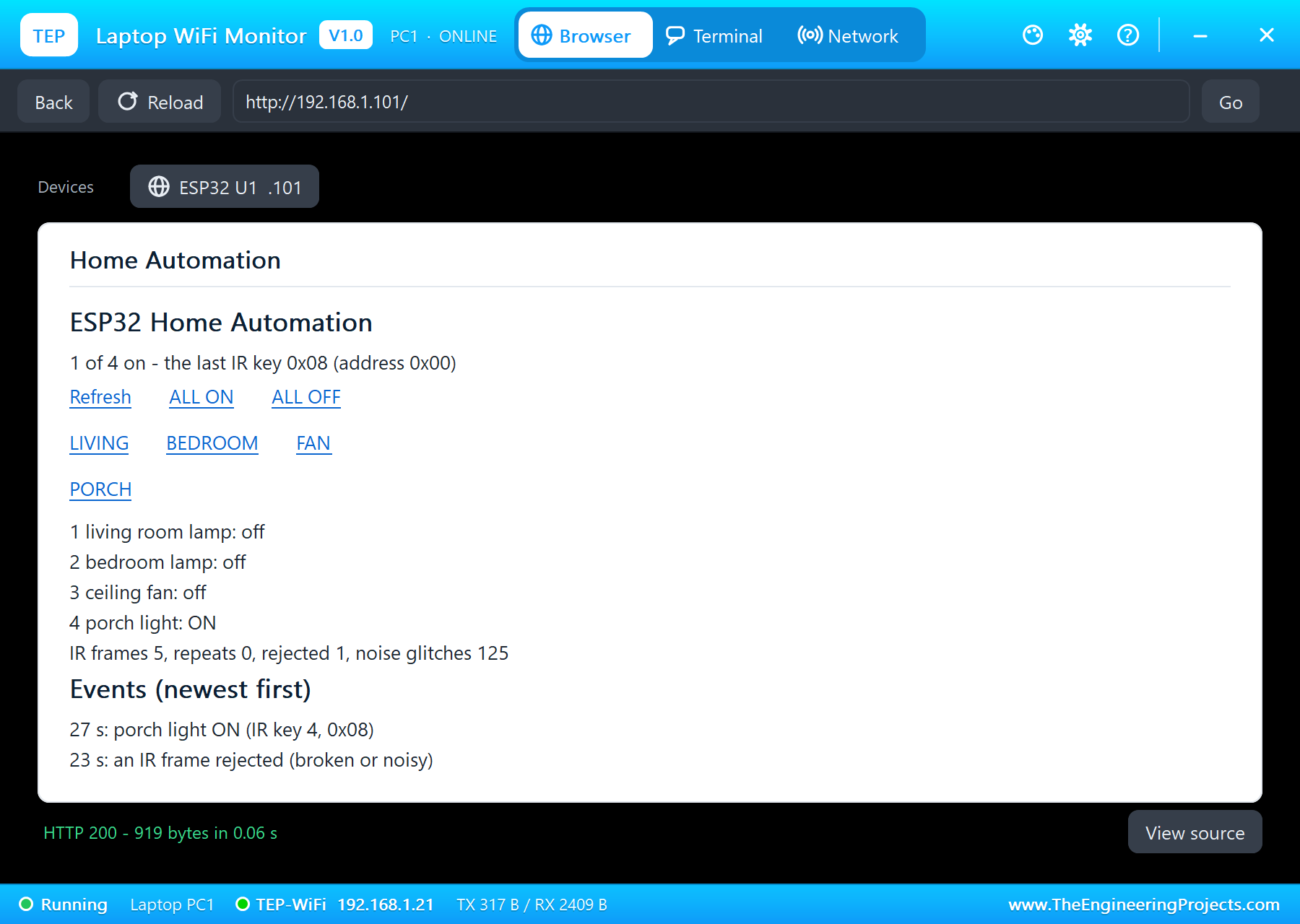
Now NOISE in the receiver's pop-up, as if a fluorescent lamp were flickering nearby, and key 4. The noise broke the frame: at 23 seconds, "an IR frame rejected (broken or noisy)", and the porch light stayed off. Meanwhile the dashboard counted 125 noise glitches, each a dip far too short for a leader, without a single line in the log. With the noise off, key 4 worked at once: "porch light ON (IR key 4, 0x08)" at 27 seconds.
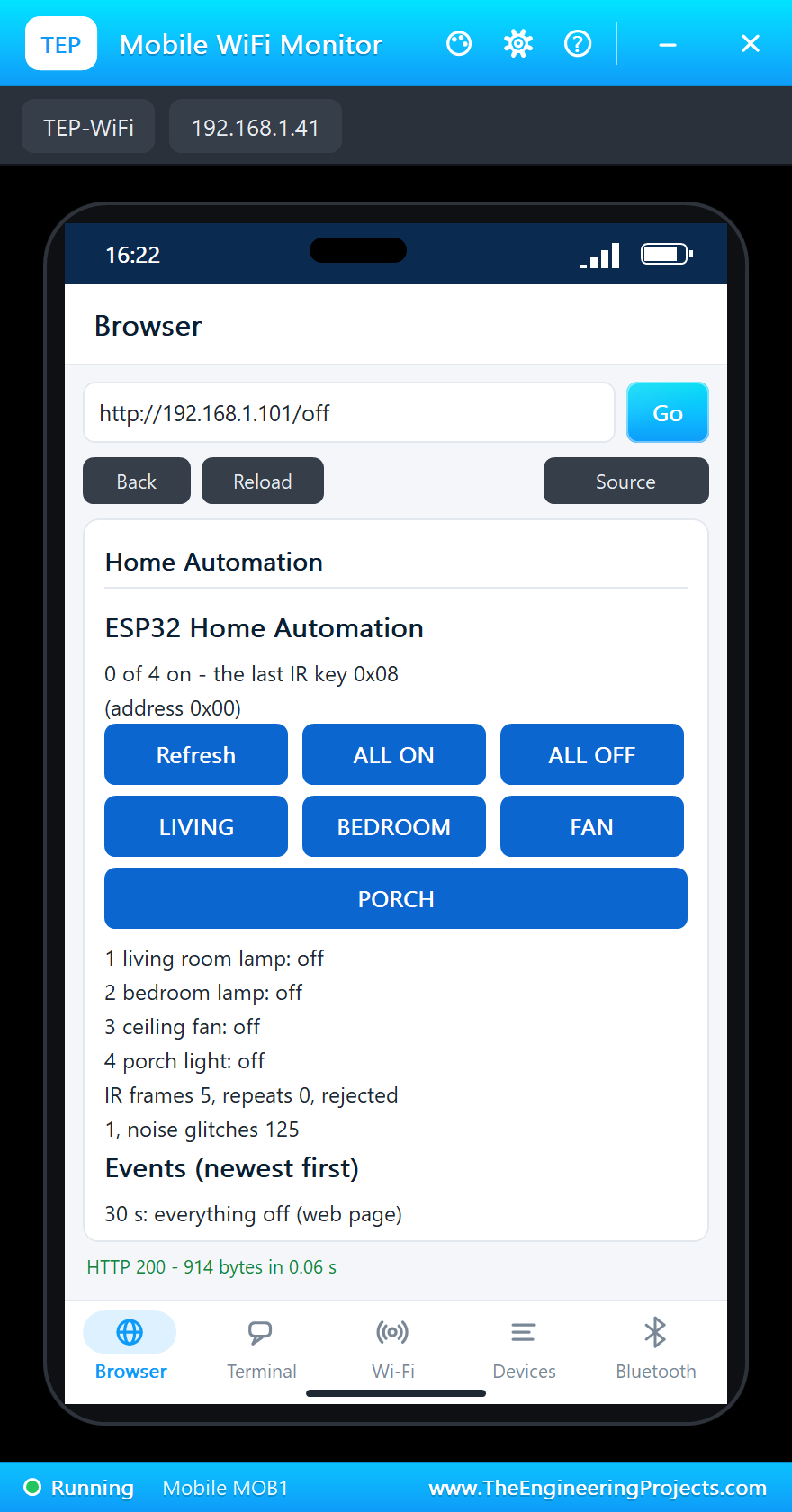
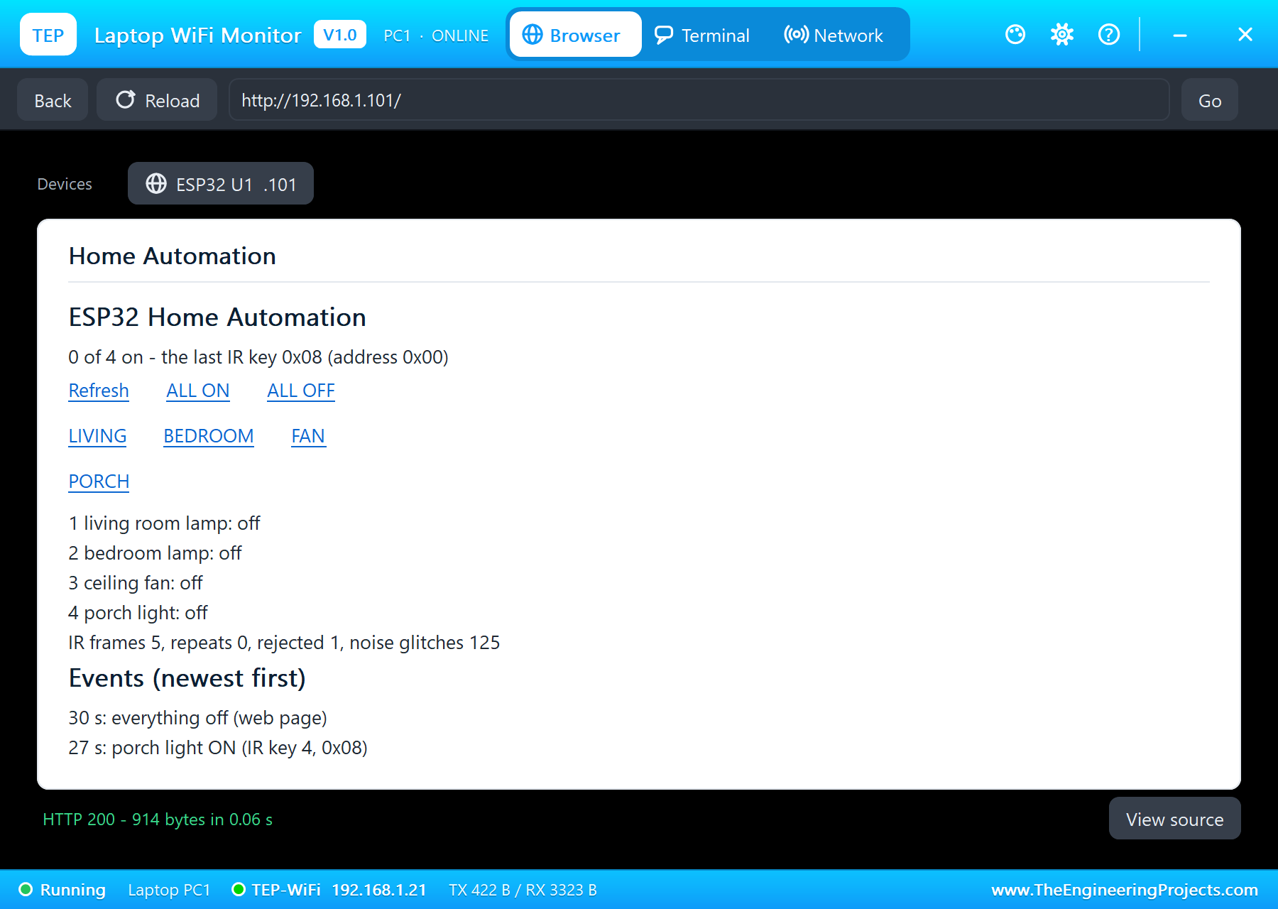
Last, ALL OFF on the phone at 30 seconds: "everything off (web page)", and the relay module was back where it started.
The serial monitor holds the whole story:
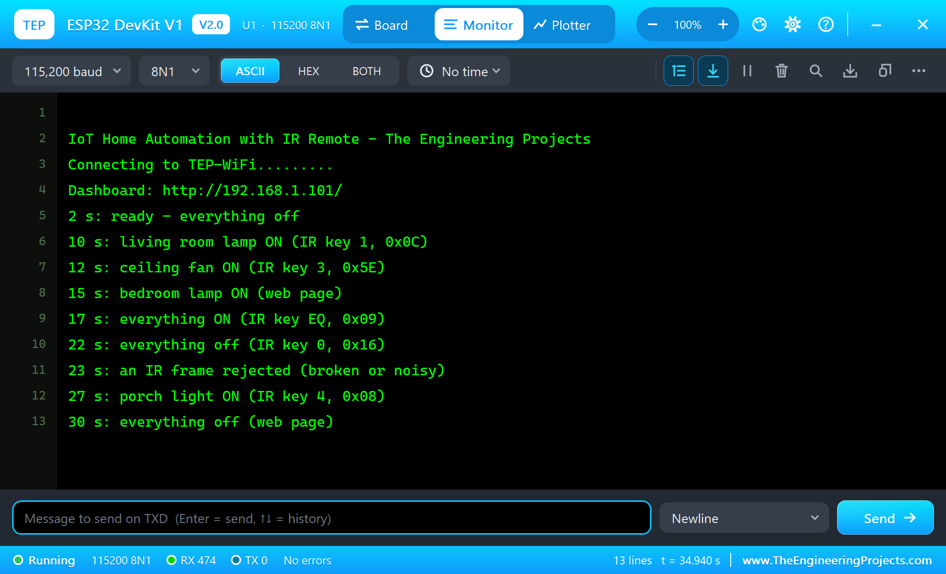
In all, 35 seconds of simulation took about 4 minutes on our PC with all the screenshots. Five frames were decoded, one broken frame was rejected and not one load ever switched by mistake.
Download the Project Files
Click the button below to download IoT-Home-Automation-ESP32-IR-Remote-Proteus-Simulation-v1.0.zip (about 4.0 MB, without the source code of the models):
IoT Home Automation with ESP32 and IR Remote - Proteus Simulation V1.0- Proteus Simulation: ESP32-IR-Home-Automation.pdsprj, ESP32_IR_Home_Automation.hex and copies of the models.
- Arduino Code: ESP32_IR_Home_Automation.ino, the complete sketch.
- Proteus Library Files: the LIB files of the ESP32 DevKit V1, the IR receiver and remote, the relay modules, the bulbs, the fan and the two WiFi Monitors.
- Proteus Model Files: the DLL models.
- README.txt: the installation steps, the properties, the test results and the links to every library post.
No Proteus yet? Read How to Download and Install Proteus 7 and 8. New to libraries? Follow How to Install a New Library in Proteus.
How to Install the Project Files
- Close Proteus and extract the whole zip file, for example to your Desktop.
- Copy the files from Proteus Library Files into the LIBRARY folder of Proteus.
- Copy the files from Proteus Model Files into the MODELS folder.
- Start Proteus and open the project from the Proteus Simulation folder.
Changing the Code
To change the sketch, install the TEP Boards for Proteus add-on from the ESP32 DevKit V1 Library for Proteus post, open the sketch in the Arduino IDE, choose ESP32 DevKit V1 (TEP Proteus), export the compiled binary and set the board's PROGRAM property to the new .hex file. The key codes are at the top; your own remote's codes can be read with the sketch's serial output. The same sketch runs on a real ESP32 Dev Module. For another ESP32 project with a dashboard, see our IoT Smart Curtain with ESP32.
Ideas to Extend the Project
- Learn any remote: press a key while the page is in LEARN mode and store its code for a load.
- Use the + and - keys to dim a lamp through a MOSFET with PWM instead of a relay.
- Add a schedule: the porch light on at sunset and off at midnight.
- Remember the loads' states in the ESP32's flash, so they come back after a power cut.
- Add wall switches as inputs, so the room works the old way as well.
- Send IR as well as receive it, and let the page switch the TV or the air conditioner.
From Simulation to Real Hardware
- Mains needs care: a real relay module switching 230 V lamps must be in a closed box, with proper wiring and fuses; if in doubt, use 12 V loads as in this project.
- Decode with interrupts: polling works here, but on a busy real ESP32 the IRremote library's interrupt-driven receiver never misses a frame.
- Power the receiver from 3.3 V: so that its output matches the ESP32's logic level.
- Give the relays their own supply: four relay coils draw about 300 mA; use the JD-VCC jumper and a separate 5 V supply for the coils to keep the ESP32 quiet.
- Keep the receiver in sight: mount it where the remote can reach it, away from direct sunlight and fluorescent lamps.
Troubleshooting
- No key works: OUT is not on D35, or the receiver has no supply; its pop-up shows what it receives.
- "an IR frame rejected": noise or a weak signal broke the frame; turn NOISE off, or move the remote closer and straighter.
- A key switches the wrong load: another remote sends other commands; change the codes at the top of the sketch.
- The relays click but a lamp stays dark: COM has no 12 V, or the lamp is on NC instead of NO.
- All relays come on at start-up: the pins were made outputs before they were set HIGH.
Limitations of the Simulation
- The remote's keys are clicked in the pop-up; the distance, the angle and the noise come from its settings.
- The lamps and the fan run from 12 V; real home automation often switches mains, which needs the care described above.
- The network is simulated: the dashboard travels between the ESP32 and the two monitors inside Proteus; the times in this tutorial are simulation time.
- ESP32 is a name of Espressif Systems and NEC of NEC Corporation; this project is not made or endorsed by them or by Labcenter.
So, that was all about the IoT Home Automation with ESP32 and IR Remote - Proteus Simulation. I hope it helps you build your own: an IR remote decoded bit by bit, each frame checked against its inverted copy, relays that switch on LOW, and a dashboard that switches the same room, all tested in a simulation before you wire a single relay. More IoT projects with the ESP32 and the Raspberry Pi 5 are coming in this series. If you have any questions, ask in the comments and I will help you out. Till the next tutorial, take care and have fun!

Comments
0