


Sharp IR Distance Sensor Library for Proteus V1.0: GP2Y0A21YK0F


Hello friends, I hope you all are doing great. Today, I am going to share the new Sharp IR Distance Sensor Library for Proteus V1.0. The Sharp GP2Y0A21YK0F is the small black sensor with two round eyes that robots use to see walls and obstacles: it measures the distance to an object from 10 to 80 cm with infrared light and gives it as an analog voltage, so any Arduino reads it with one analogRead(). Now you can test those projects in Proteus.
Behind the part sits our own model, not a voltage source with a knob. It follows the datasheet: the output curve, a new measurement every 38.3 ms, the noise of each measurement, the 30 mA it draws, and its classic trap - an object closer than about 6 cm gives a voltage that looks like a farther object. You move the object in 5 cm steps, pick a preset, or run a sweep, an approach or a passing hand. You get two devices: a Simple device with a live STATUS panel and the object's controls, and an Advance device with a pop-up window and the test tools. The demo runs on our Arduino UNO V4.0 and needs no library.
NOTICE: an analog distance sensor is easy to fake: one voltage source and a formula. We wanted more. Our GP2Y0A21YK0F measures in cycles like the real one, so a sketch that reads too fast, averages the wrong way or trusts an object that is too close fails exactly as it does on your desk. It took our team a lot of hard work. Your feedback is the fuel that keeps us going, so please tell us what you think in the comments below or in the Sharp IR distance board of our forum. And if our free libraries help you, you can buy us a coffee. So, let's get started with the Sharp IR Distance Sensor Library for Proteus V1.0:
What is the Sharp GP2Y0A21YK0F?
The GP2Y0A21YK0F from Sharp is an infrared distance sensor in one small package: an IR LED, a lens, a position-sensitive detector (PSD) behind a second lens, and the circuit that turns the spot's position into a voltage. It has no bus and no library: three wires, and the distance comes out as a voltage on VO. Sharp's IR distance sensors also appear in our Interface Sharp Infrared Distance Measurement Sensor with Raspberry Pi 4 tutorial. For distances with sound, see our Ultrasonic Sensor Library for Proteus; for a simple yes / no obstacle detector, our Infrared Sensor Library for Proteus.
| GP2Y0A21YK0F | |
|---|---|
| Range | 10 to 80 cm |
| Output | analog VO: 0.4 V at 80 cm, 1.9 V more at 10 cm (2.3 V); about 1 / distance |
| Measuring cycle | 38.3 ms (+-9.6 ms), the result on VO within 5 ms |
| Supply | 4.5 to 5.5 V, 30 mA average (40 mA maximum); absolute maximum 7 V |
| Connector | JST, 3 pins: 1 VO, 2 GND, 3 VCC |
| Size | 44.5 mm across its two mounting ears |
| Devices | GP2Y0A21TEP (Simple) and GP2Y0A21ADVTEP (Advance) |
How It Measures: Triangulation
The IR LED sends a narrow beam out of one lens. The object reflects a spot of it back through the other lens onto the PSD. The farther the object, the smaller the angle, and the nearer the spot lands to one end of the PSD. The sensor works out the spot's position, not how much light comes back, so the colour of the object matters much less than with a simple IR reflector. One measurement takes about 38 ms; then the result goes to VO and stays there until the next one.
The Output Curve
| Distance | VO | analogRead (5 V) |
|---|---|---|
| 10 cm | 2.30 V | 471 |
| 15 cm | 1.65 V | 337 |
| 20 cm | 1.30 V | 266 |
| 30 cm | 0.92 V | 188 |
| 50 cm | 0.60 V | 122 |
| 80 cm | 0.40 V | 81 |
VO falls with the distance, roughly as 1 / distance. That makes the near end fine and the far end coarse: from 10 to 20 cm VO falls by 1 V, from 50 to 80 cm by only 0.2 V. A power law fits the curve well; the demo uses distance = 27.19 x VO^-1.189, within about 1 % from 10 to 80 cm.
The Trap: Too Close Reads Far
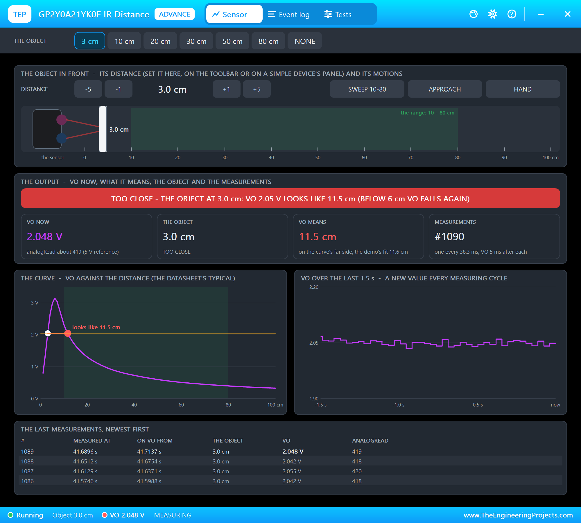
Below about 6 cm the curve turns around. The peak is about 3.15 V; closer than that, VO falls again. An object at 3 cm gives 2.05 V - the same as an object at 11.5 cm. The sensor cannot tell the two apart, and neither can your sketch. That is why the datasheet starts the range at 10 cm, and why a robot should mount the sensor a little back from its bumper. Our model has the whole curve, so you can see this trap in Proteus.
What's New in Sharp IR Distance Sensor Library for Proteus V1.0
- The real sensor: the GP2Y0A21YK0F seen from the front - the black body, the emitter's and the detector's lenses, the two mounting ears - with its JST cable (red VCC, black GND, yellow VO) and a 3-pin plug as the pins.
- Two styles: a Simple device with a STATUS panel and an Advance device with a pop-up window; the PWR and IR LEDs and the panel button sit on the sensor's body.
- The datasheet's output: the typical curve from 1 to 150 cm with its peak near 6 cm, a new value every 38.3 ms on VO 5 ms after each measurement, 0 V until the first result, the noise of each measurement, 30 mA on VCC.
- The object on the panel: its distance in 5 cm steps, seven presets (3, 10, 20, 30, 50, 80 cm and NONE) and three motions: SWEEP 10-80, APPROACH and HAND.
- The classic trap: an object closer than 6 cm reads as a farther one - the panel turns red and shows what VO looks like; notes for an object closer than 10 cm, beyond 80 cm, nothing in front and a supply out of range.
- Three test tools on the Advance device: Output & curve, Timing, and Supply & wiring.
- A two-node demo on our Arduino UNO V4.0 with no library: a median of five readings, the distance from a power law, RAW.
- A compact package: about 1.27 MB, without the C++ source code of the model.
Two Devices: Simple and Advance
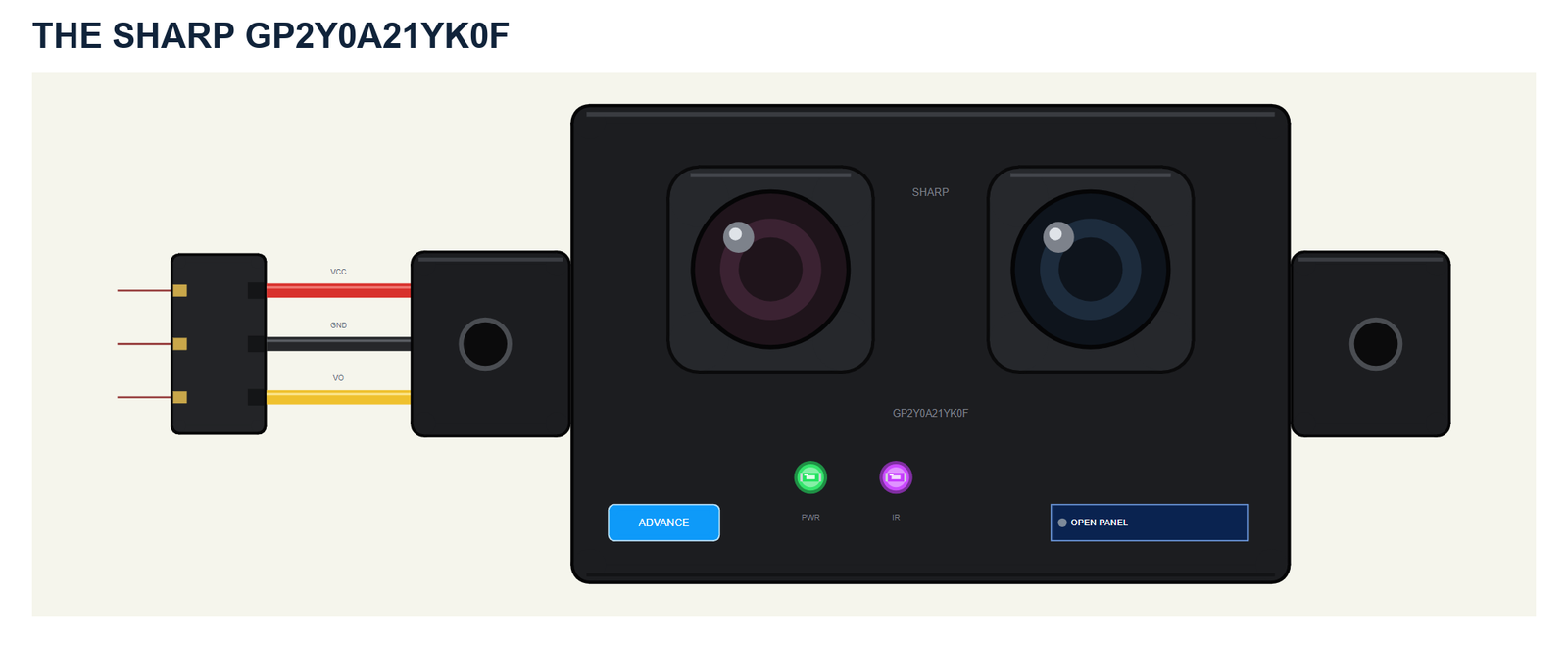
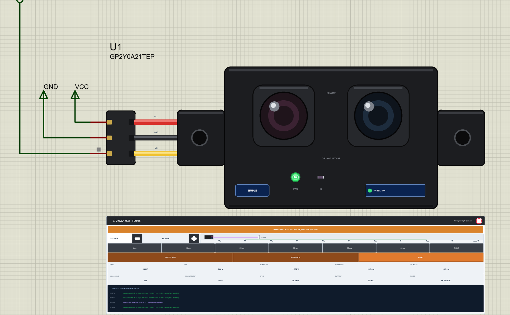
The sensor shows its two lens housings - in our drawing the emitter's on the left with a reddish lens, the detector's on the right - between the two mounting ears. Its cable comes out from behind the left ear: the red, black and yellow wires end in a 3-pin plug, and the plug's pins VCC, GND and VO are the part's pins.
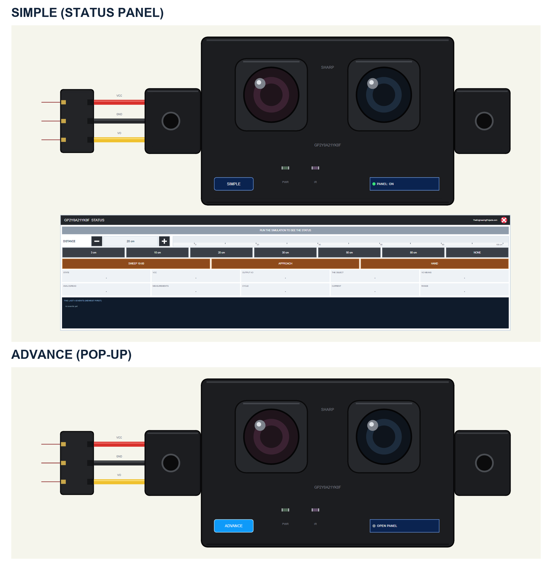
| Simple | Advance | |
|---|---|---|
| Device | GP2Y0A21TEP | GP2Y0A21ADVTEP |
| On the schematic | The sensor and the STATUS panel | The sensor |
| The object and its motions | On the STATUS panel | In the pop-up |
| Status | Banner, a ruler, 10 readouts, the last 4 events | A pop-up: Sensor, Event log, Tests |
Download Sharp IR Distance Sensor Library for Proteus
Click the button below to download Sharp-IR-Distance-Sensor-Library-for-Proteus-v1.0.zip (about 1.27 MB, without the C++ source code of the model):
Sharp IR Distance Sensor Library for Proteus V1.0: GP2Y0A21YK0F- README.txt: the devices, installation, the demo, wiring, the test tools and real hardware.
- Proteus Library Files:
TEPSHARPIR.LIBandArduinoV4TEP.LIBfrom our Arduino Library for Proteus V4.0. - Proteus Model Files:
TEPSHARPIR.DLLandTEPARDUINO.DLL. - Proteus Simulation:
GP2Y0A21YK0F-IR-Distance-ArduinoUnoV4.pdsprj,GP2Y0A21_Distance_Demo.hexand copies of the two DLLs. - Arduino Code:
GP2Y0A21_Distance_Demo.ino- it needs no library.
No Proteus yet? Read How to Download and Install Proteus 7 and 8. New to libraries? Follow How to Install a New Library in Proteus.
How to Install Sharp IR Distance Sensor Library for Proteus
- Close Proteus and extract the whole zip file, for example to your Desktop.
- Copy the two files from Proteus Library Files into the LIBRARY folder of Proteus (usually
C:\Program Files (x86)\Labcenter Electronics\Proteus 8 Professional\LIBRARY). - Copy
TEPSHARPIR.DLLandTEPARDUINO.DLLfrom Proteus Model Files into the MODELS folder. - Delete
TEPSHARPIR.IDXfrom the LIBRARY folder if it is there. - Start Proteus, press P and search for GP2Y0A21 or Sharp.
Tip: keep the Proteus Simulation folder together, because the project needs its .hex file and the DLLs beside it. The library is tested in Proteus 8.5; Proteus 7 is not supported.
The GP2Y0A21YK0F Parts in Proteus
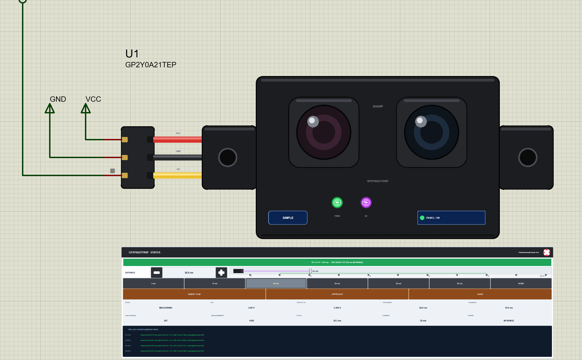
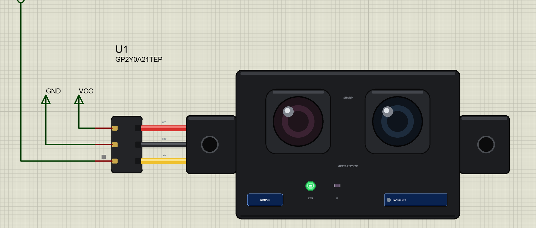
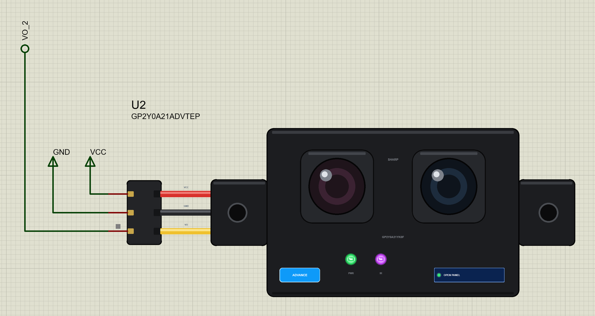
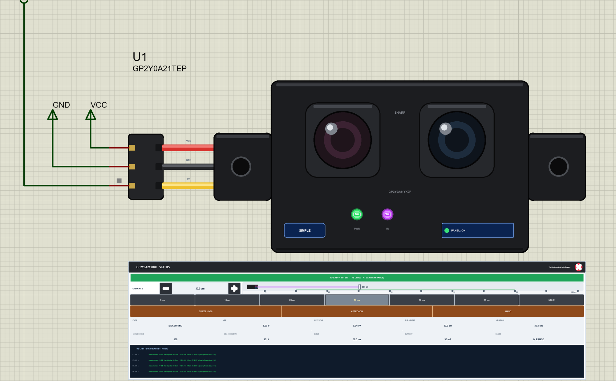
Two LEDs sit on the sensor's body: PWR while VCC is there, and IR, which blinks with the measurements. Next to the SIMPLE or ADVANCE badge is the panel button. The LEDs, the badge, the button and the panels are TEP additions; the real sensor has none of them.
The Simple device adds the STATUS panel. Its banner shows VO, what it means and where the object really is; it turns amber while the object moves or is out of range, and red when the object is too close. Below it are the controls: DISTANCE with - and + (5 cm a click) and a ruler from 0 to 100 cm, where the beam and the object move live; seven presets; and three motions - SWEEP 10-80, APPROACH and HAND. Ten readouts follow - the state, VCC, VO, the object, what VO means, the analogRead it gives, the measurements, the cycle, the current and the range - and the last four events.
The red X closes the STATUS panel, and the PANEL button on the body opens it again:
The Advance device keeps the schematic clean: only the sensor. Its live data opens in a pop-up window at Run, and the OPEN PANEL button on the body brings the window back. The properties set the start: DISTANCE (the object in cm, 0 for nothing in front), CYCLE (38.3 ms) and NOISE (6 mV RMS).
The Demo Circuit
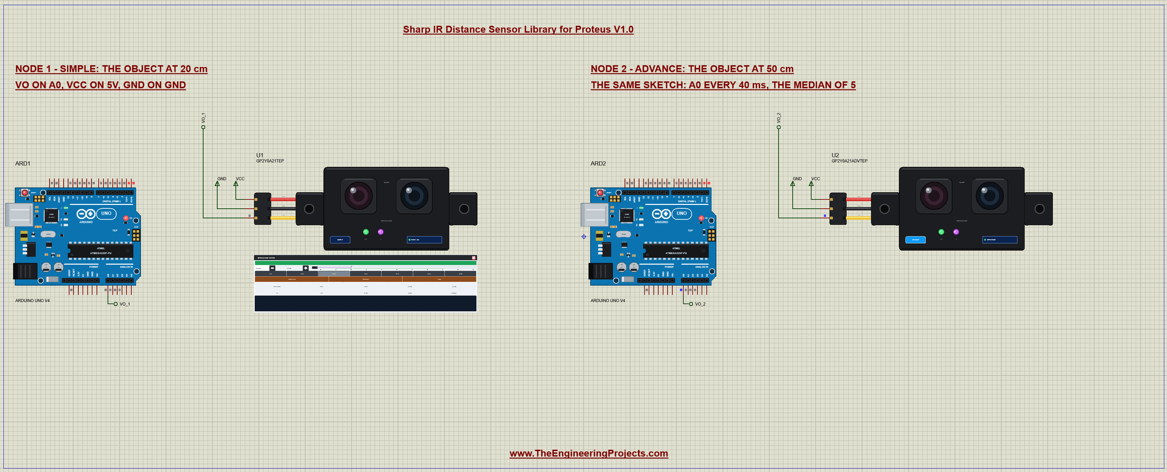
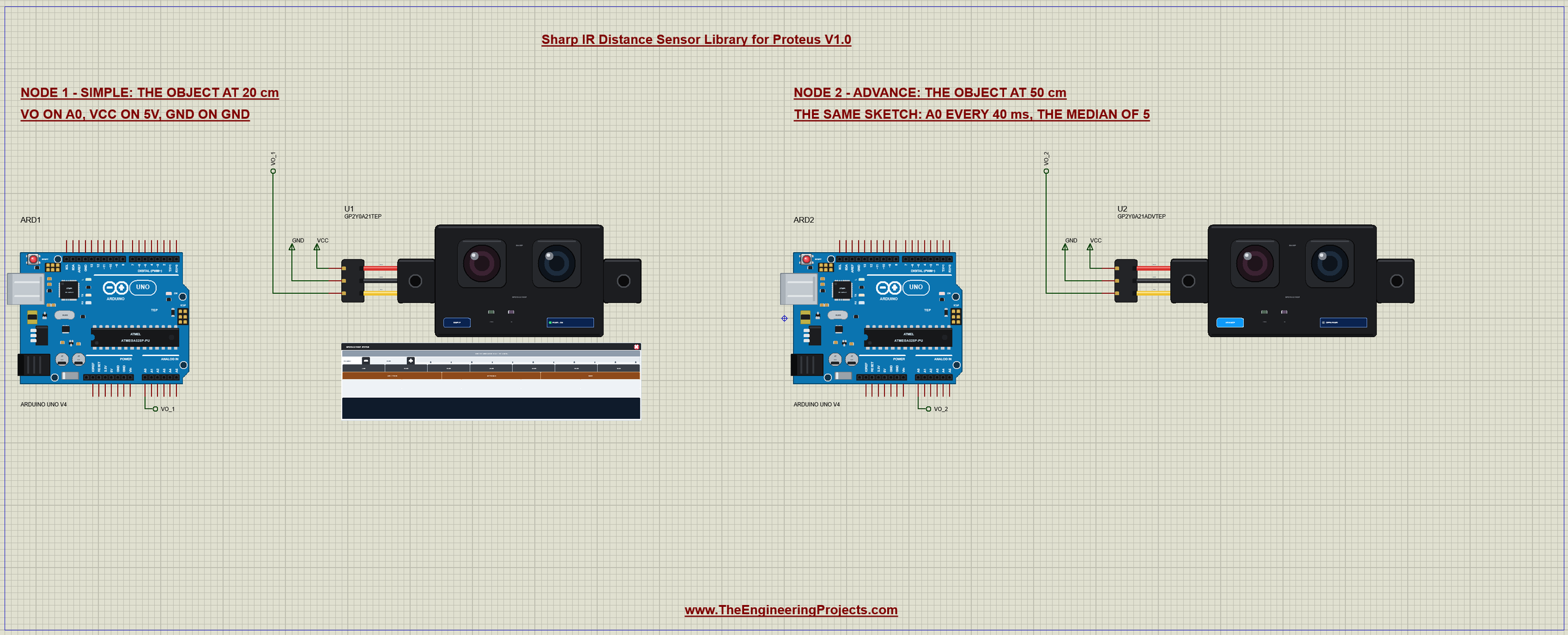
The demo project has two nodes. Each one is an Arduino UNO V4.0 from our Arduino UNO Library for Proteus V4.0 with a GP2Y0A21YK0F whose VO goes to A0. Node 1 starts with the object at 20 cm; node 2 at 50 cm. Both UNOs run the same GP2Y0A21_Distance_Demo.hex.
Wiring
| Sensor | Arduino UNO |
|---|---|
| VCC (red) | 5V |
| GND (black) | GND |
| VO (yellow) | A0 (any analog input) |
In Proteus, VO reaches its UNO through net labels, VO_1 for node 1 and VO_2 for node 2; VCC and GND are power terminals. The serial monitor needs no wires at all, because it is built into the UNO V4.0. On a real board, add a 10 uF capacitor across VCC and GND close to the sensor.
The Arduino Code
The demo sketch needs no library at all - just analogRead(). New to Arduino? Start with Arduino Tutorial for Beginners and Introduction to Arduino UNO; for analog readings in Proteus, see Display ADC value on LCD using Arduino in Proteus. The sketch keeps the formula in two constants:
const uint8_t IR_PIN = A0;
const float FIT_A = 27.19, FIT_B = -1.189;       // distance (cm) = FIT_A x VO^FIT_B
The sensor gives a new value only every 38.3 ms, so the loop reads A0 once per measuring cycle, every 40 ms, into a ring of five readings:
  if ((long)(millis() - nextSample) >= 0) {     // one reading per measuring cycle
    samples[head] = analogRead(IR_PIN);
    head = (head + 1) % 5;
    if (nSamples < 5) nSamples++;
    nextSample += 40;
  }
Twice a second it takes the median of those readings, so one bad reading cannot move the result, and turns it into volts and centimetres:
int median() {
  int s[5];
  for (uint8_t i = 0; i < nSamples; i++) s[i] = samples[i];
  for (uint8_t i = 1; i < nSamples; i++)
    for (uint8_t j = i; j > 0 && s[j - 1] > s[j]; j--) { int x = s[j]; s[j] = s[j - 1]; s[j - 1] = x; }
  return s[nSamples / 2];
}
void printReading() {
int a = median();
float v = volts(a);
Serial.print('#'); Serial.print(++count);
Serial.print(F(" A0 ")); Serial.print(a);
Serial.print(F(" ")); Serial.print(v, 2); Serial.print(F(" V "));
if (v < 0.35) { // below the curve's 80 cm: nothing in range
Serial.println(F("nothing in range (beyond 80 cm)"));
return;
}
float d = FIT_A * pow(v, FIT_B);
Serial.print(d, 1); Serial.print(F(" cm"));
if (d > 80) Serial.println(F(" - beyond 80 cm"));
else Serial.println();
}Below 0.35 V there is nothing within about 90 cm, so the sketch says so instead of printing a huge distance. Note what the sketch cannot do: tell an object at 3 cm from one at 11.5 cm - more on that below. RAW reads A0 20 times, 5 ms apart:
void raw() {
  Serial.print(F("RAW:"));
  for (uint8_t i = 0; i < 20; i++) {
    Serial.print(' '); Serial.print(analogRead(IR_PIN));
    delay(5);
  }
  Serial.println();
}
The HEX file is in the package, so you do not need the Arduino IDE to run the demo. To change the sketch, open it in the Arduino IDE and export the compiled binary, as in How to get the HEX file from Arduino. It needs 7,142 bytes of flash and 270 bytes of RAM.
The Serial Monitor
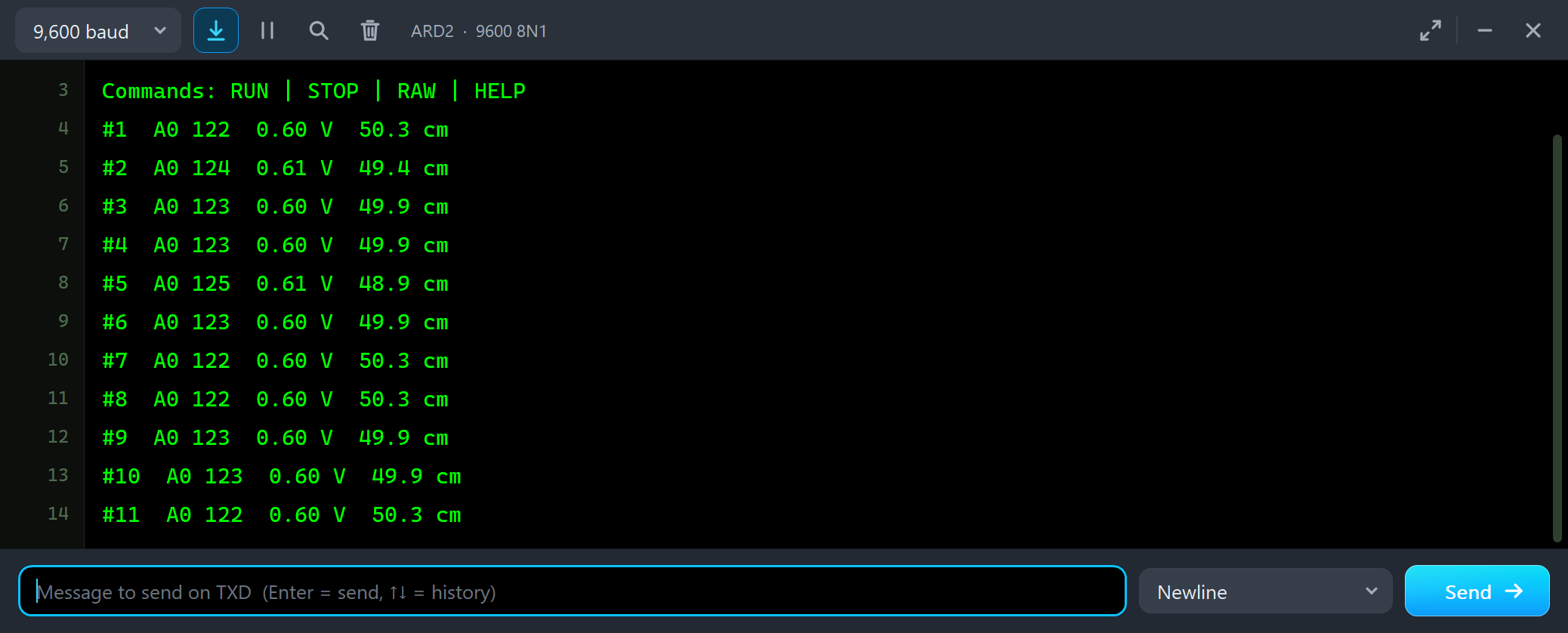
Both UNOs have the serial monitor built in, and it opens at Run. The screenshots use its Simple interface. Node 2 starts like this:
Commands: RUN | STOP | RAW | HELP
#1  A0 122  0.60 V  50.3 cm
#2  A0 124  0.61 V  49.4 cm
#3  A0 123  0.60 V  49.9 cm
#4  A0 123  0.60 V  49.9 cm
#5  A0 125  0.61 V  48.9 cm
A0 reads 122 to 125, about 0.60 V, and the formula gives 48.9 to 50.3 cm for an object at 50 cm. The small changes are the noise of each measurement; a real sensor wobbles the same way. Node 1 reads its object at 20 cm:
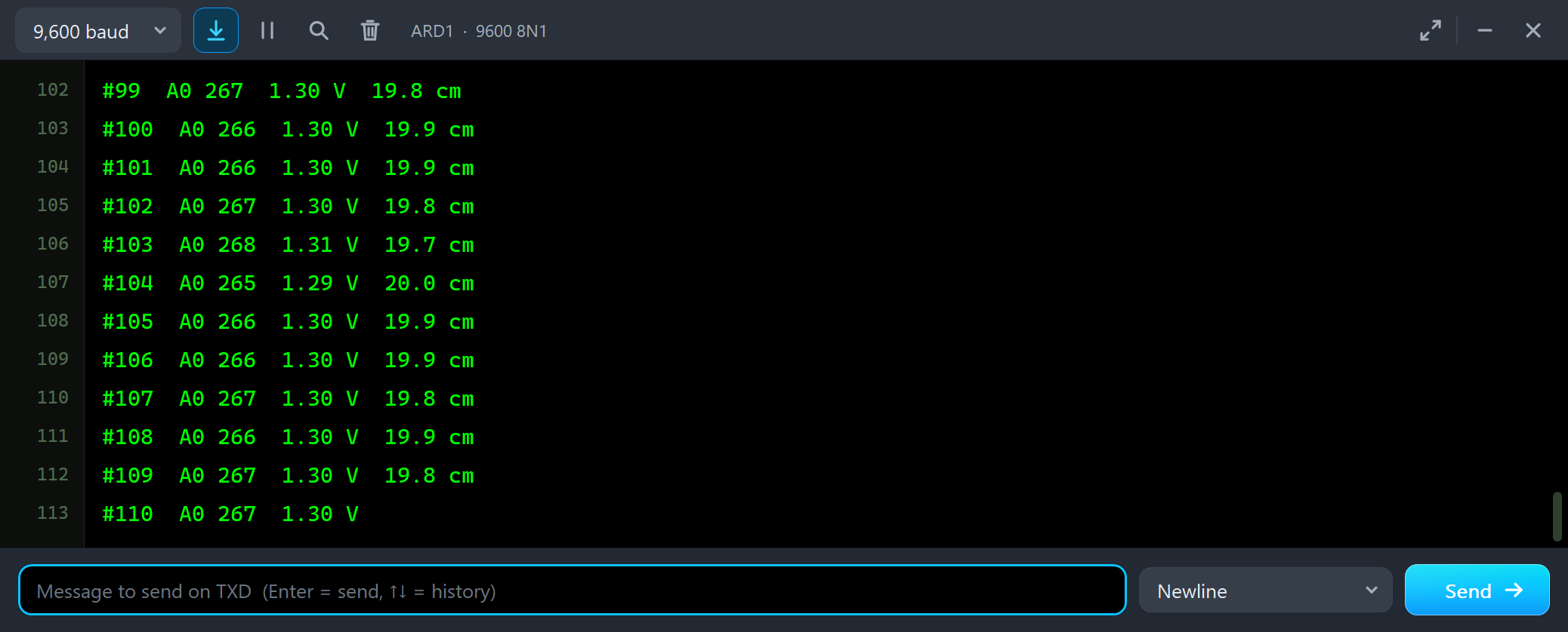
#100  A0 266  1.30 V  19.9 cm
#101  A0 266  1.30 V  19.9 cm
#102  A0 267  1.30 V  19.8 cm
#103  A0 268  1.31 V  19.7 cm
#104  A0 265  1.29 V  20.0 cm
Move the Object on the STATUS Panel
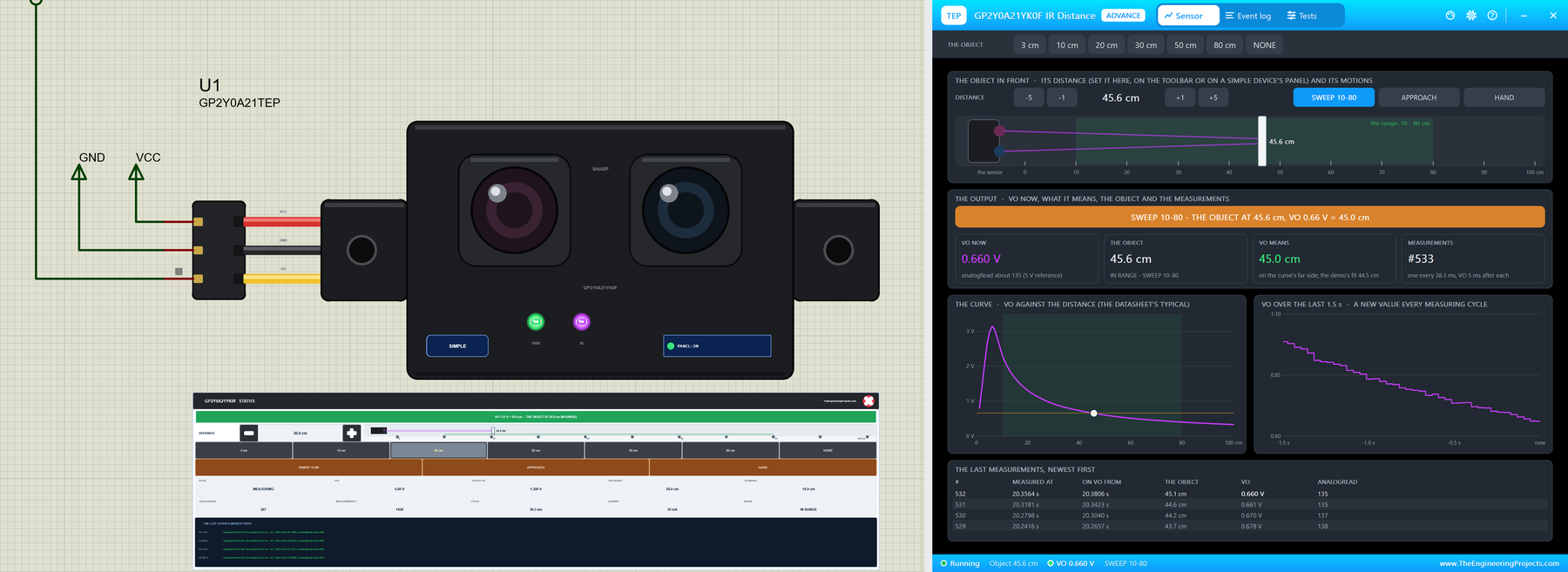
Now let's move the object while the simulation runs. We clicked the + button of U1's panel twice with the mouse:
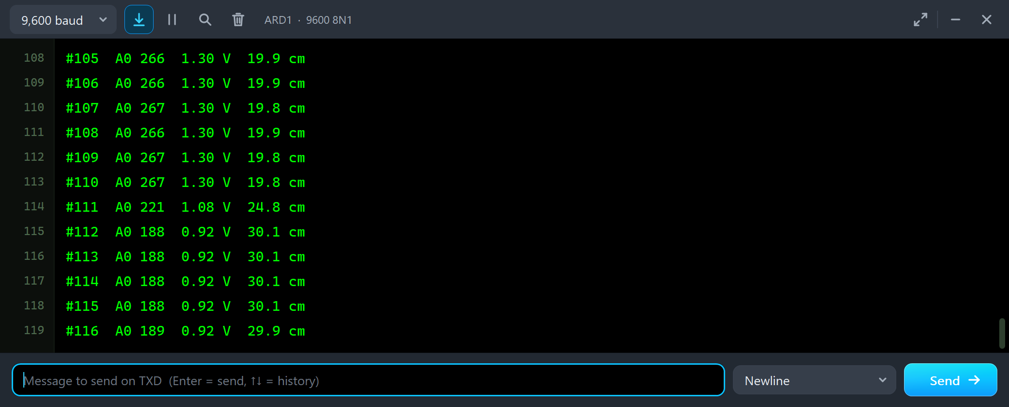
#108  A0 266  1.30 V  19.9 cm
#109  A0 267  1.30 V  19.8 cm
#110  A0 267  1.30 V  19.8 cm
#111  A0 221  1.08 V  24.8 cm
#112  A0 188  0.92 V  30.1 cm
#113  A0 188  0.92 V  30.1 cm
One line shows 24.8 cm: the median of five readings, 40 ms apart, takes a moment to follow a jump. Then HAND: a hand comes in to 15 cm, stays 1.8 s and goes again.
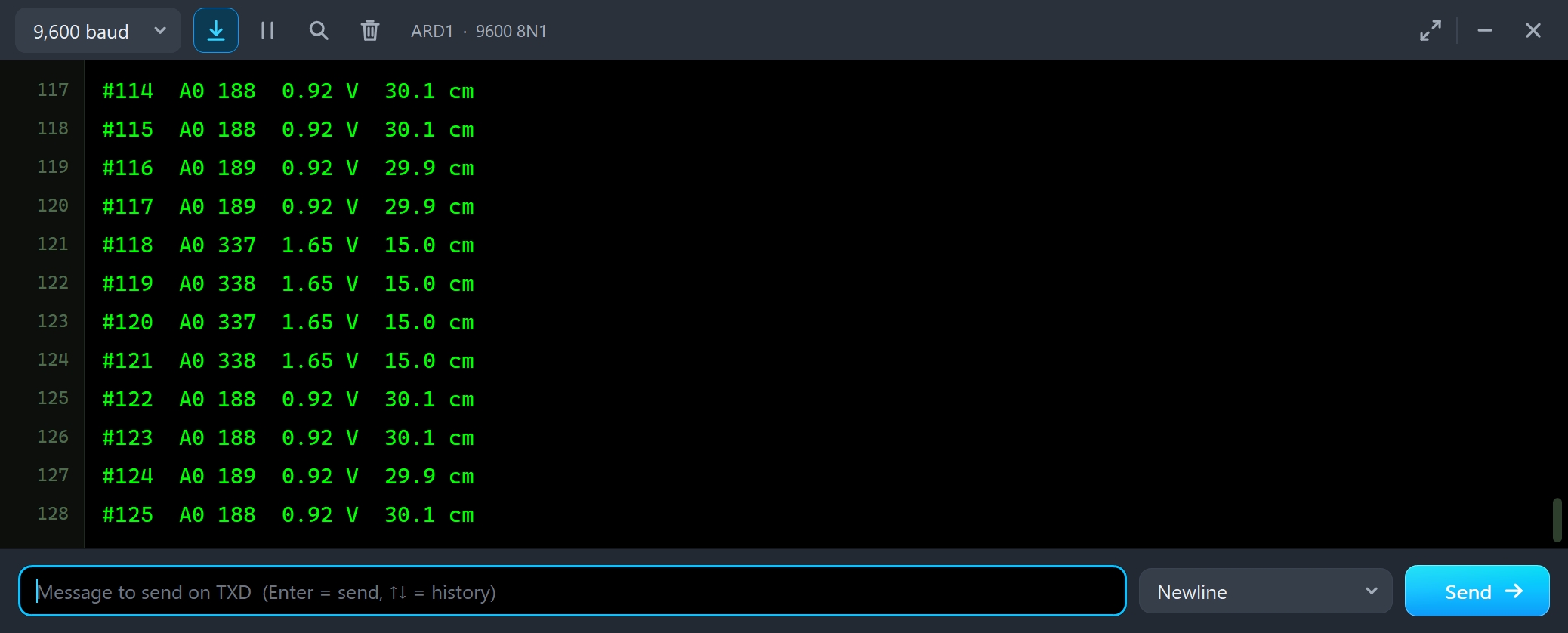
#116  A0 189  0.92 V  29.9 cm
#117  A0 189  0.92 V  29.9 cm
#118  A0 337  1.65 V  15.0 cm
#119  A0 338  1.65 V  15.0 cm
#120  A0 337  1.65 V  15.0 cm
#121  A0 338  1.65 V  15.0 cm
#122  A0 188  0.92 V  30.1 cm
#123  A0 188  0.92 V  30.1 cm
This is how a robot sees an obstacle that comes and goes. Last, the 3 cm preset:
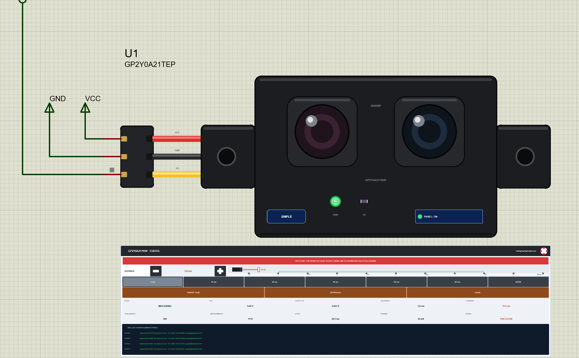
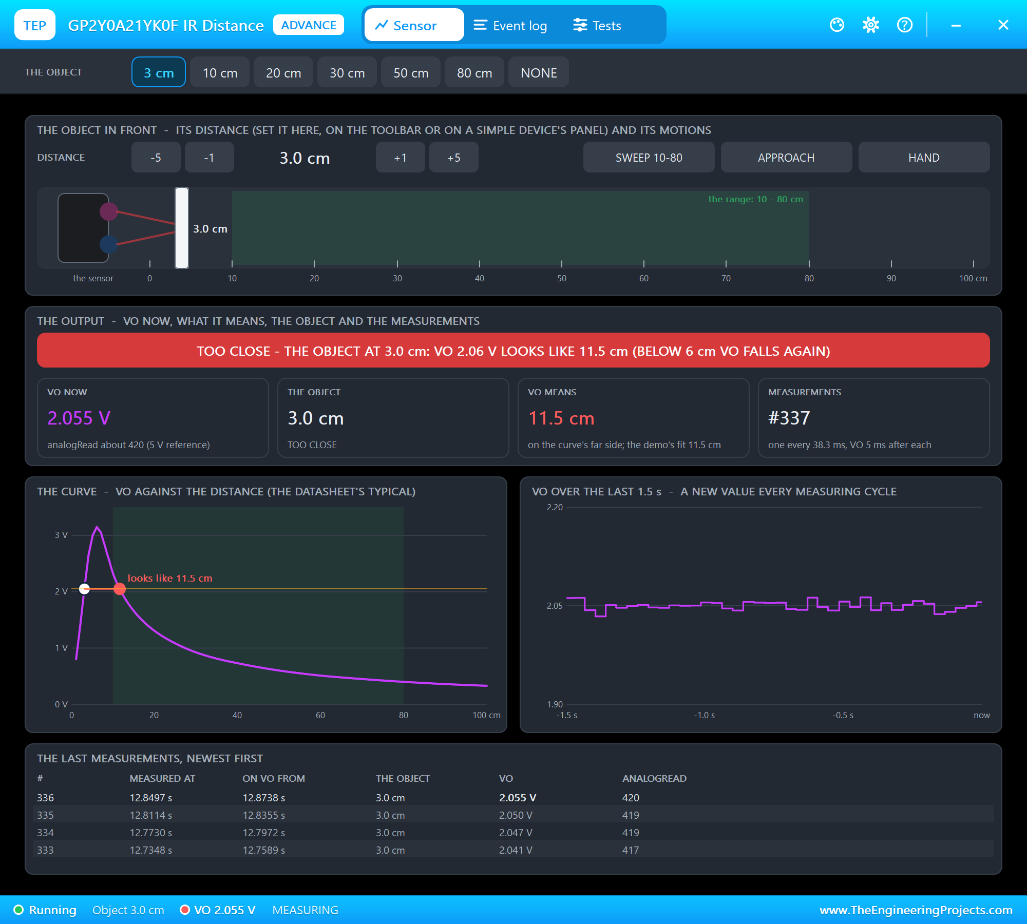
The panel turns red: the object is at 3 cm, but its VO of 2.05 V means 11.5 cm on the curve. The sketch will print about 11.6 cm, a perfectly believable distance. We will see this again on node 2.
The Advance Pop-Up Window
At Run, the Advance sensor opens its own window, GP2Y0A21YK0F IR Distance, with the look of our TEP Serial Monitor Advance for Proteus. It has three tabs, Sensor, Event log and Tests, plus Settings and Help behind the gear and question mark icons. The status bar at the bottom always shows the object, VO and the state.
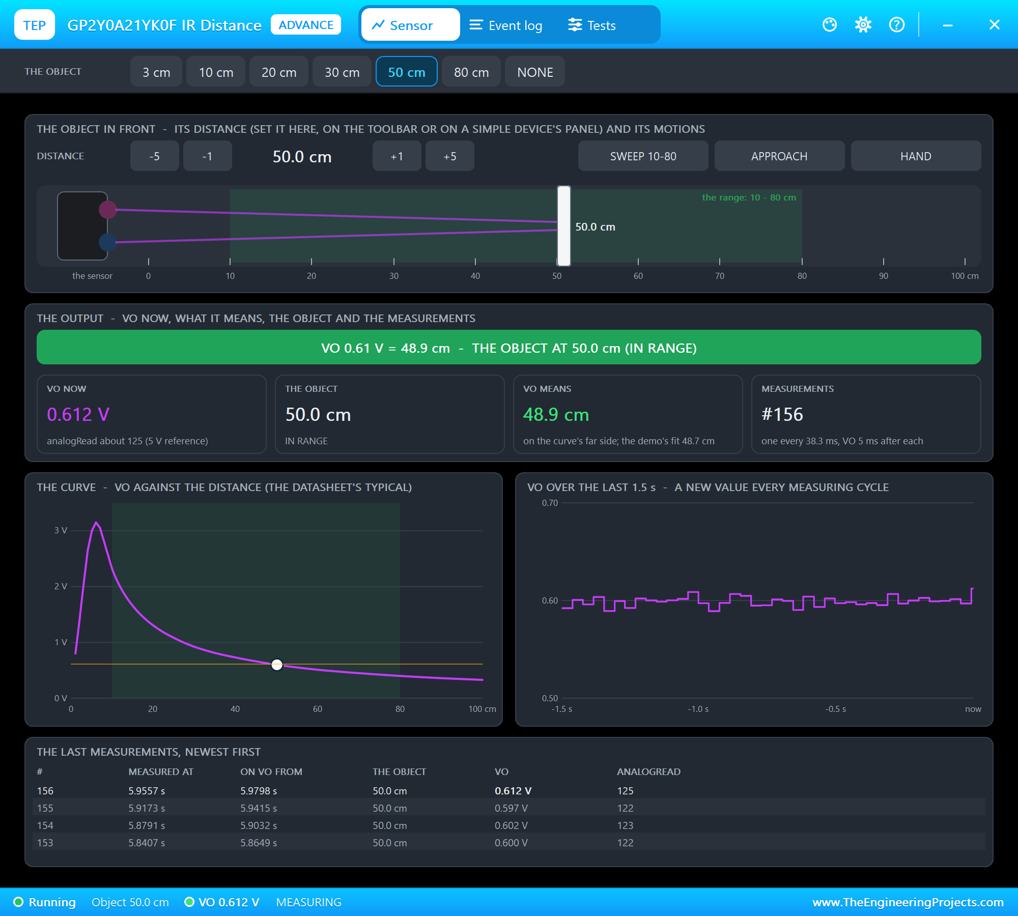
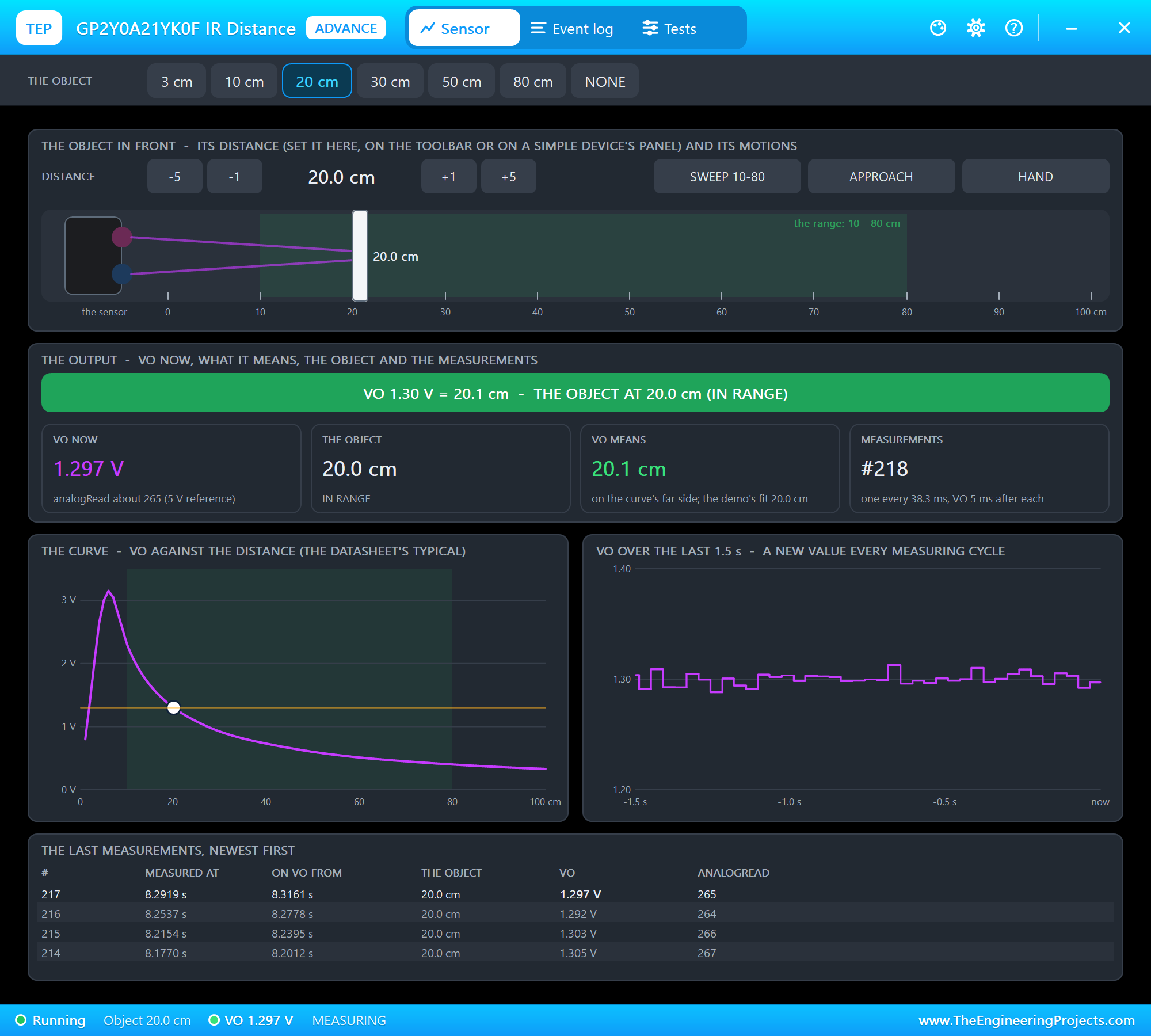
The toolbar carries the presets. The object in front has -5, -1, +1 and +5 cm, the three motions and a side view: the sensor, its beam and the object on a ruler, the 10 to 80 cm range shaded green. The output shows VO now with its analogRead, the object, what VO means on the curve (and with the demo's formula) and the number of measurements. The curve draws VO against the distance with the object's point, and VO over the last 1.5 s shows the output's steps. At the bottom are the last measurements with the time each was measured and the time its result appeared on VO. We clicked 20 cm:
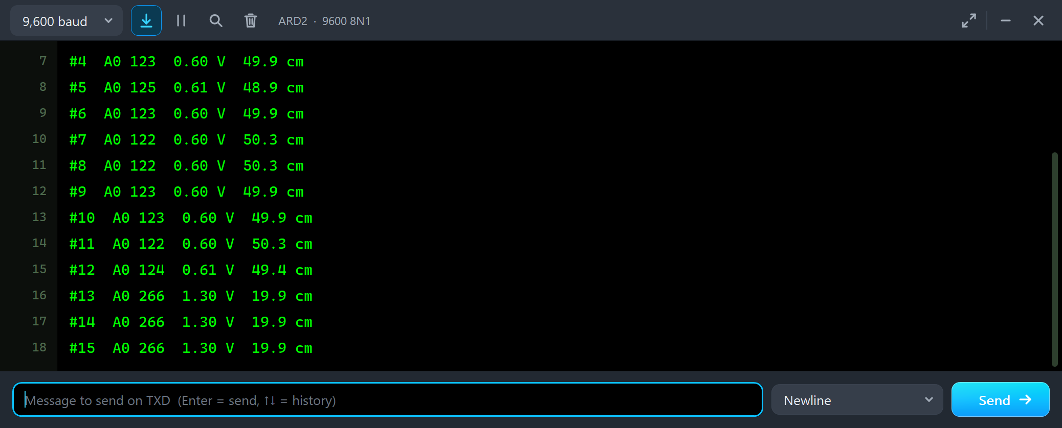
#10  A0 123  0.60 V  49.9 cm
#11  A0 122  0.60 V  50.3 cm
#12  A0 124  0.61 V  49.4 cm
#13  A0 266  1.30 V  19.9 cm
#14  A0 266  1.30 V  19.9 cm
#15  A0 266  1.30 V  19.9 cm
RAW: One Value per Cycle
Then we typed RAW, which reads A0 twenty times, 5 ms apart:
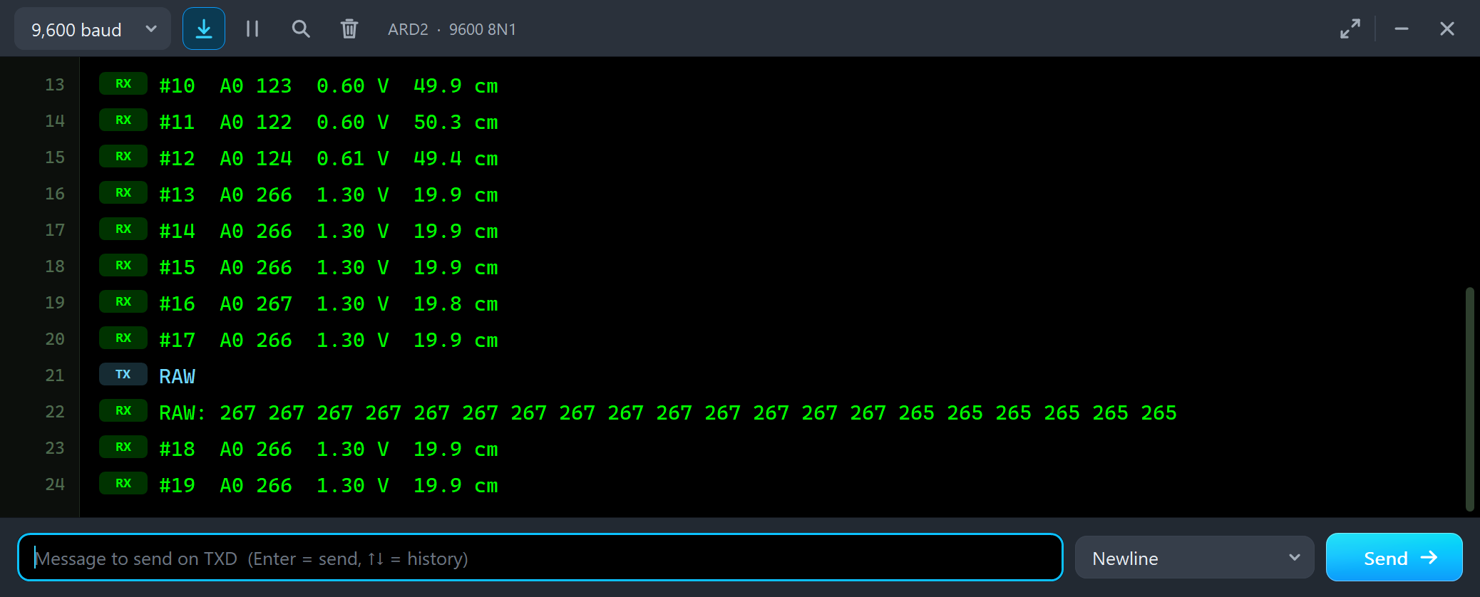
#17  A0 266  1.30 V  19.9 cm
RAW
RAW: 267 267 267 267 267 267 267 267 267 267 267 267 267 267 265 265 265 265 265 265
#18  A0 266  1.30 V  19.9 cm
Twenty readings, but only two values. VO changes only when a new measurement is out, every 38.3 ms, and two measurements in a row can give the same count. That is why averaging many reads inside one cycle does not lower the noise: it averages the same number. The demo reads once per cycle and takes the median.
3 cm: the Trap
Now the classic mistake. We clicked 3 cm:
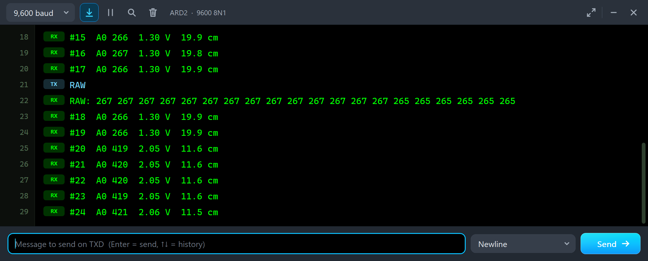
#18  A0 266  1.30 V  19.9 cm
#19  A0 266  1.30 V  19.9 cm
#20  A0 419  2.05 V  11.6 cm
#21  A0 420  2.05 V  11.6 cm
#22  A0 420  2.05 V  11.6 cm
#23  A0 419  2.05 V  11.6 cm
#24  A0 421  2.06 V  11.5 cm
The object moved from 20 cm to 3 cm, closer, but the reading fell only to 11.6 cm, a value well inside the range. On the curve card the white point sits on the left of the peak, and the red line shows its twin on the far side. The Output & curve tool spells it out:
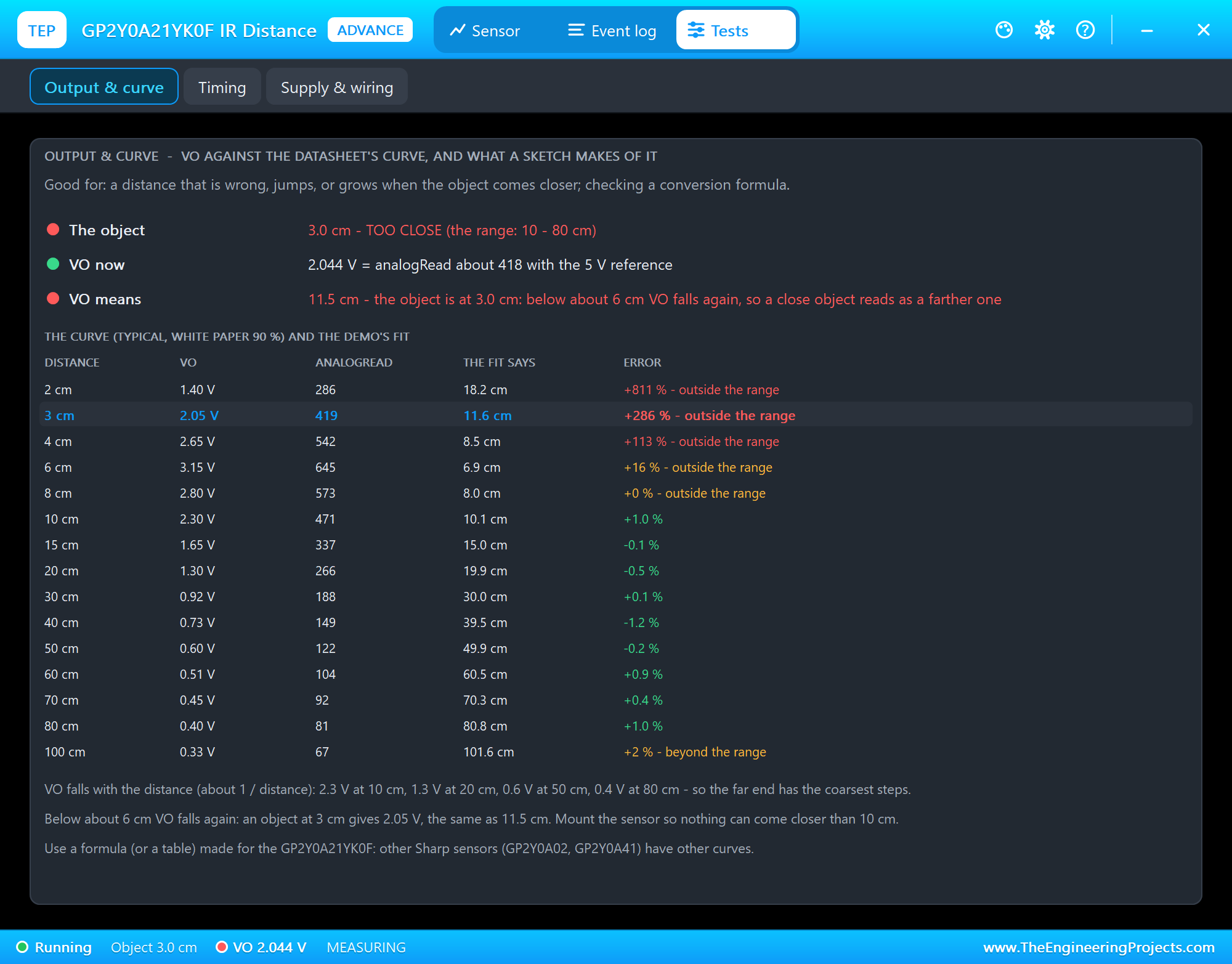
Its table lists the curve from 2 to 100 cm: VO, the analogRead, what the demo's formula says and its error - about 1 % from 10 to 80 cm, and far off below 10 cm. The fix is mechanical, not in code: mount the sensor so nothing can come closer than 10 cm.
Nothing in Front
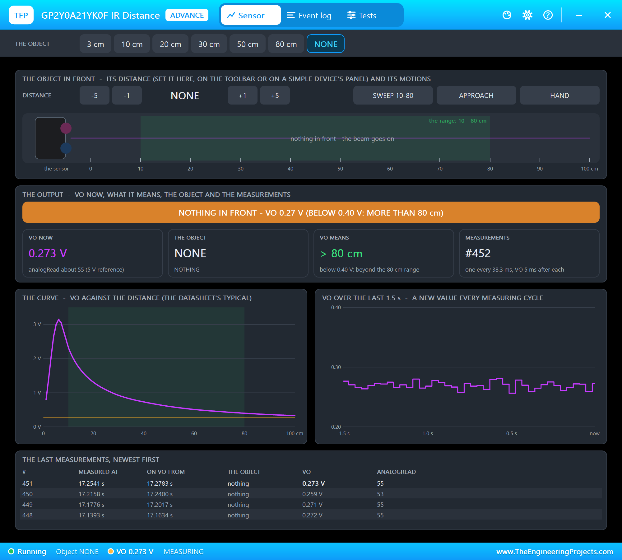
With NONE there is nothing within reach:
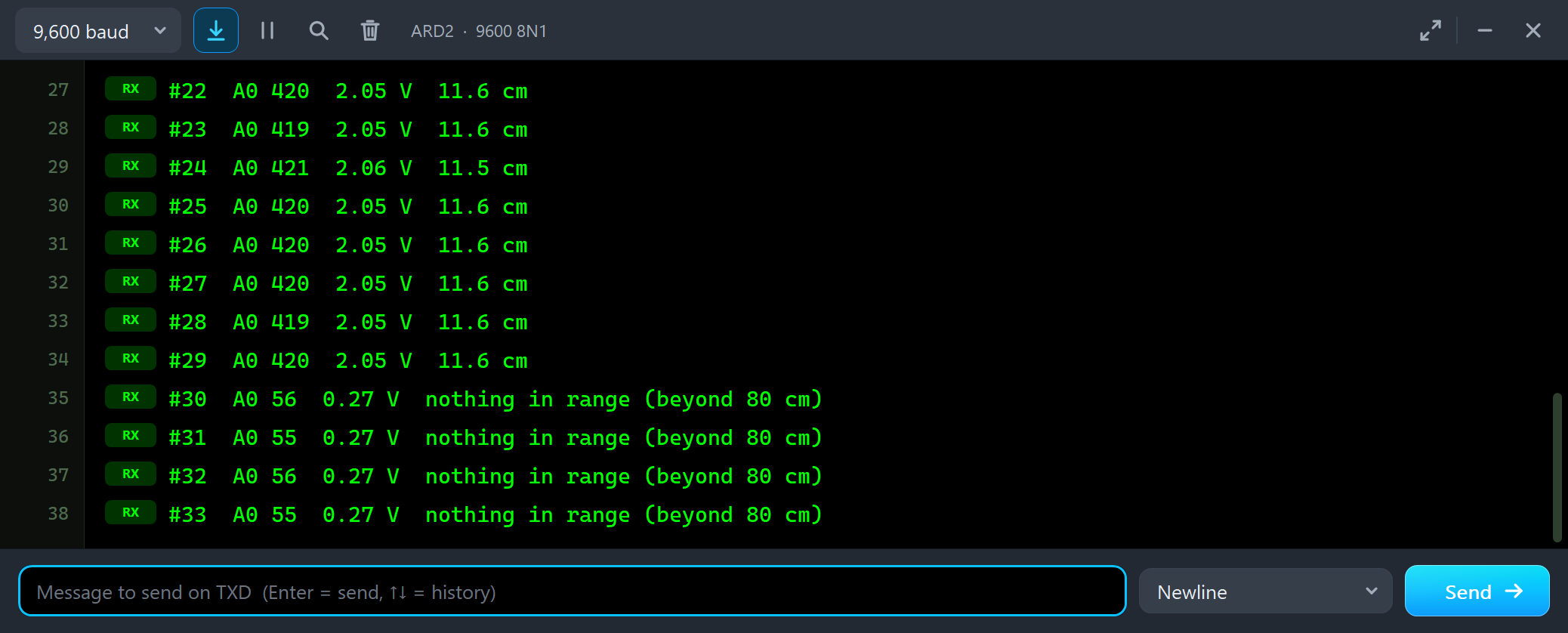
#28  A0 419  2.05 V  11.6 cm
#29  A0 420  2.05 V  11.6 cm
#30  A0 56  0.27 V  nothing in range (beyond 80 cm)
#31  A0 55  0.27 V  nothing in range (beyond 80 cm)
#32  A0 56  0.27 V  nothing in range (beyond 80 cm)
VO drops to about 0.27 V. The demo treats anything below 0.35 V as nothing in range, instead of printing a distance of a metre or more that the sensor cannot measure.
SWEEP 10-80
SWEEP 10-80 moves the object from 10 to 80 cm and back in 12 seconds:
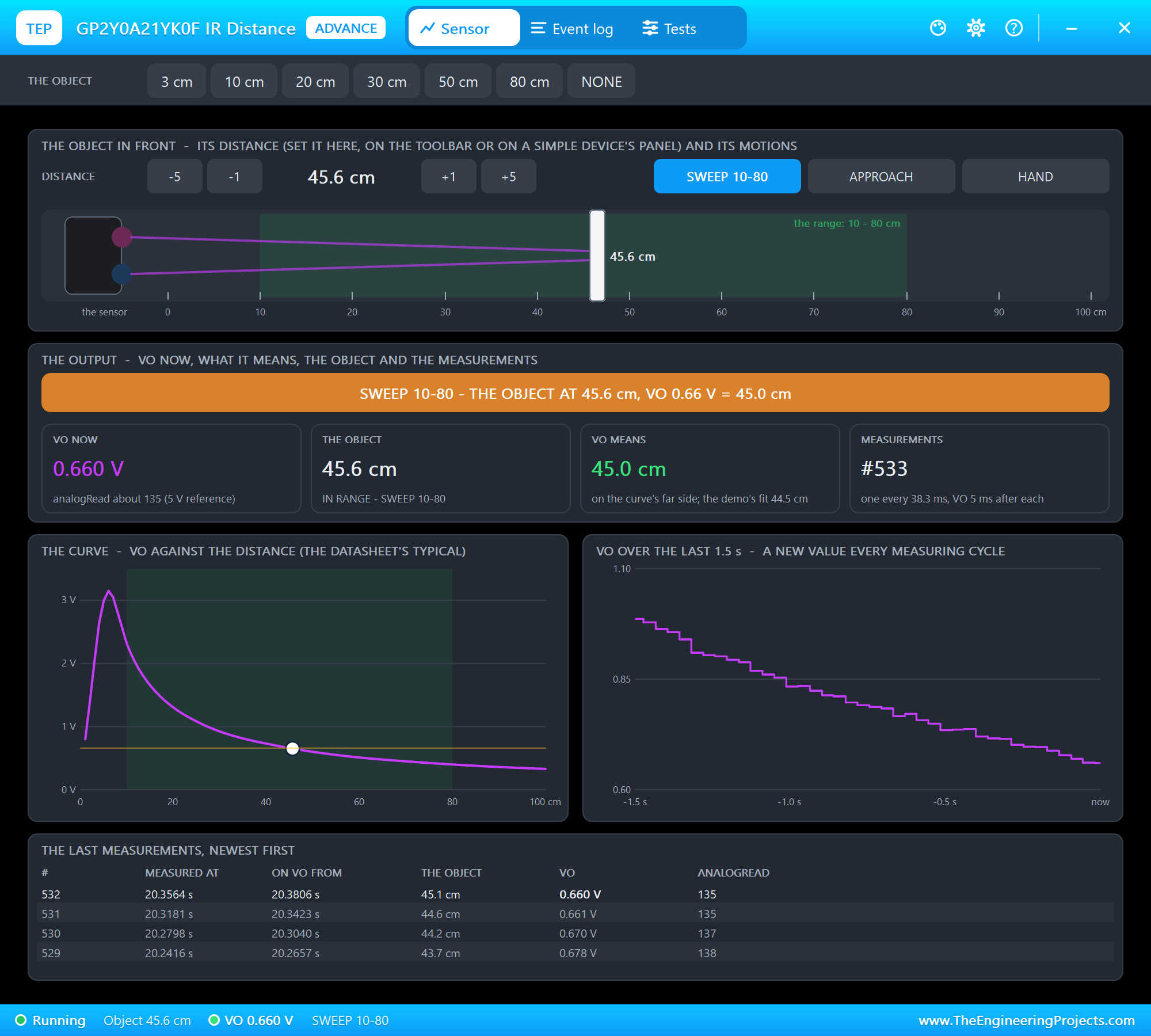
Look at VO over the last 1.5 s: not a smooth line, but a staircase with one step every 38.3 ms. Each step is one measurement. The monitor follows the sweep out:
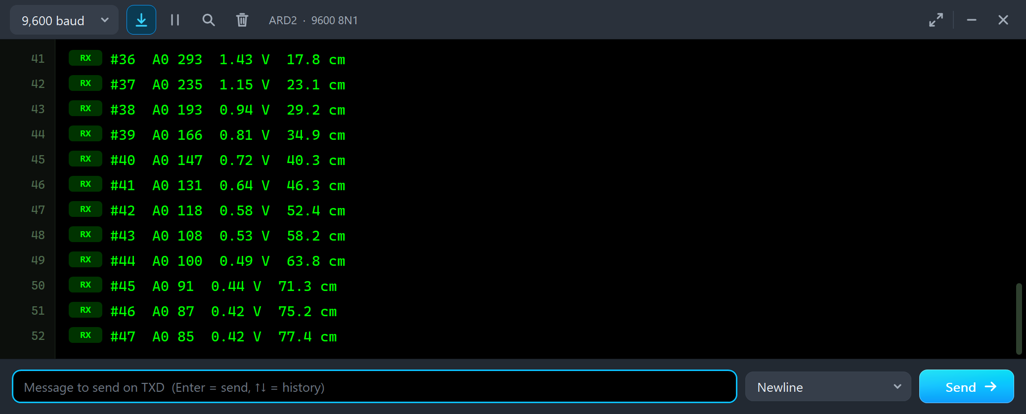
#36  A0 293  1.43 V  17.8 cm
#37  A0 235  1.15 V  23.1 cm
#38  A0 193  0.94 V  29.2 cm
#39  A0 166  0.81 V  34.9 cm
#40  A0 147  0.72 V  40.3 cm
#41  A0 131  0.64 V  46.3 cm
#42  A0 118  0.58 V  52.4 cm
#43  A0 108  0.53 V  58.2 cm
#44  A0 100  0.49 V  63.8 cm
#45  A0 91  0.44 V  71.3 cm
#46  A0 87  0.42 V  75.2 cm
#47  A0 85  0.42 V  77.4 cm
and back in:
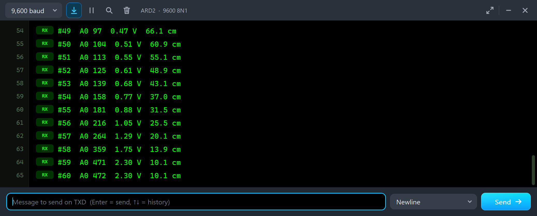
#53  A0 139  0.68 V  43.1 cm
#54  A0 158  0.77 V  37.0 cm
#55  A0 181  0.88 V  31.5 cm
#56  A0 216  1.05 V  25.5 cm
#57  A0 264  1.29 V  20.1 cm
#58  A0 359  1.75 V  13.9 cm
#59  A0 471  2.30 V  10.1 cm
#60  A0 472  2.30 V  10.1 cm
Look at the analogRead column. From 10 to 20 cm A0 changes by more than 200 counts; from 70 to 80 cm by only about 10. That is the 1 / distance curve: a centimetre far away is worth much less of VO than a centimetre close by.
APPROACH: the Trap in Motion
APPROACH brings the object from 80 cm all the way to 3 cm in 10 seconds, slower as it comes close:
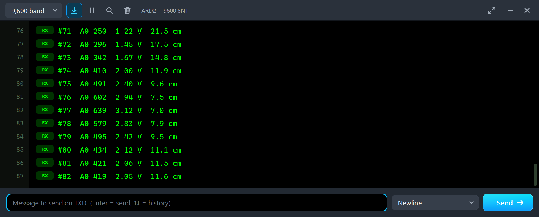
#71  A0 250  1.22 V  21.5 cm
#72  A0 296  1.45 V  17.5 cm
#73  A0 342  1.67 V  14.8 cm
#74  A0 410  2.00 V  11.9 cm
#75  A0 491  2.40 V  9.6 cm
#76  A0 602  2.94 V  7.5 cm
#77  A0 639  3.12 V  7.0 cm
#78  A0 579  2.83 V  7.9 cm
#79  A0 495  2.42 V  9.5 cm
#80  A0 434  2.12 V  11.1 cm
#81  A0 421  2.06 V  11.5 cm
#82  A0 419  2.05 V  11.6 cm
This is the trap in one picture. While the object comes in, the readings fall to 7.0 cm, the peak of the curve. Then, as the object keeps coming closer, they rise again: 7.9, 9.5, 11.1 and 11.6 cm. A robot that slows down as an obstacle gets near would speed up again just before it hits it.
The Test Tools
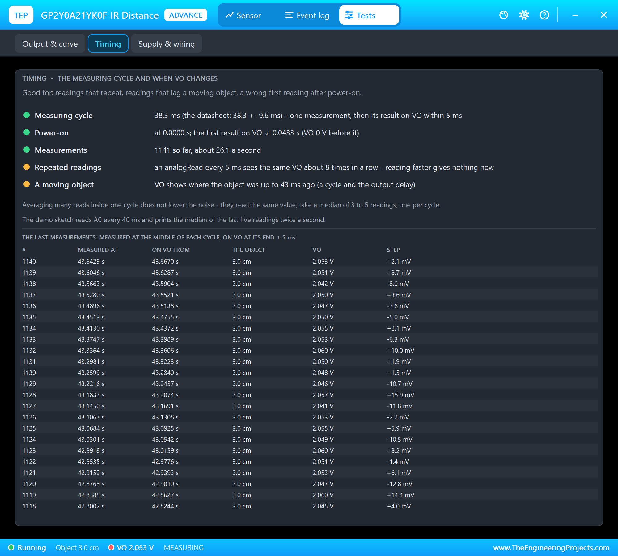
The Timing tool is the one to open for readings that repeat or lag. It shows the measuring cycle, when the first result came after power-on (43.3 ms), about 26 measurements a second, how often a fast loop reads the same value, and how old VO can be. Below, the last measurements with the time each was measured, the time its result reached VO and the step from the one before. The Supply & wiring tool checks the power and the output pin:
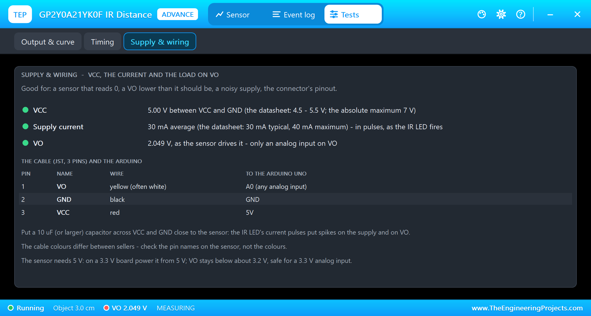
It checks VCC against 4.5 to 5.5 V, shows the current, and compares the VO the sensor drives with the VO on the pin, so a wrong load on VO stands out. Below are the connector's pins with the usual wire colours and the Arduino pins.
The Event Log
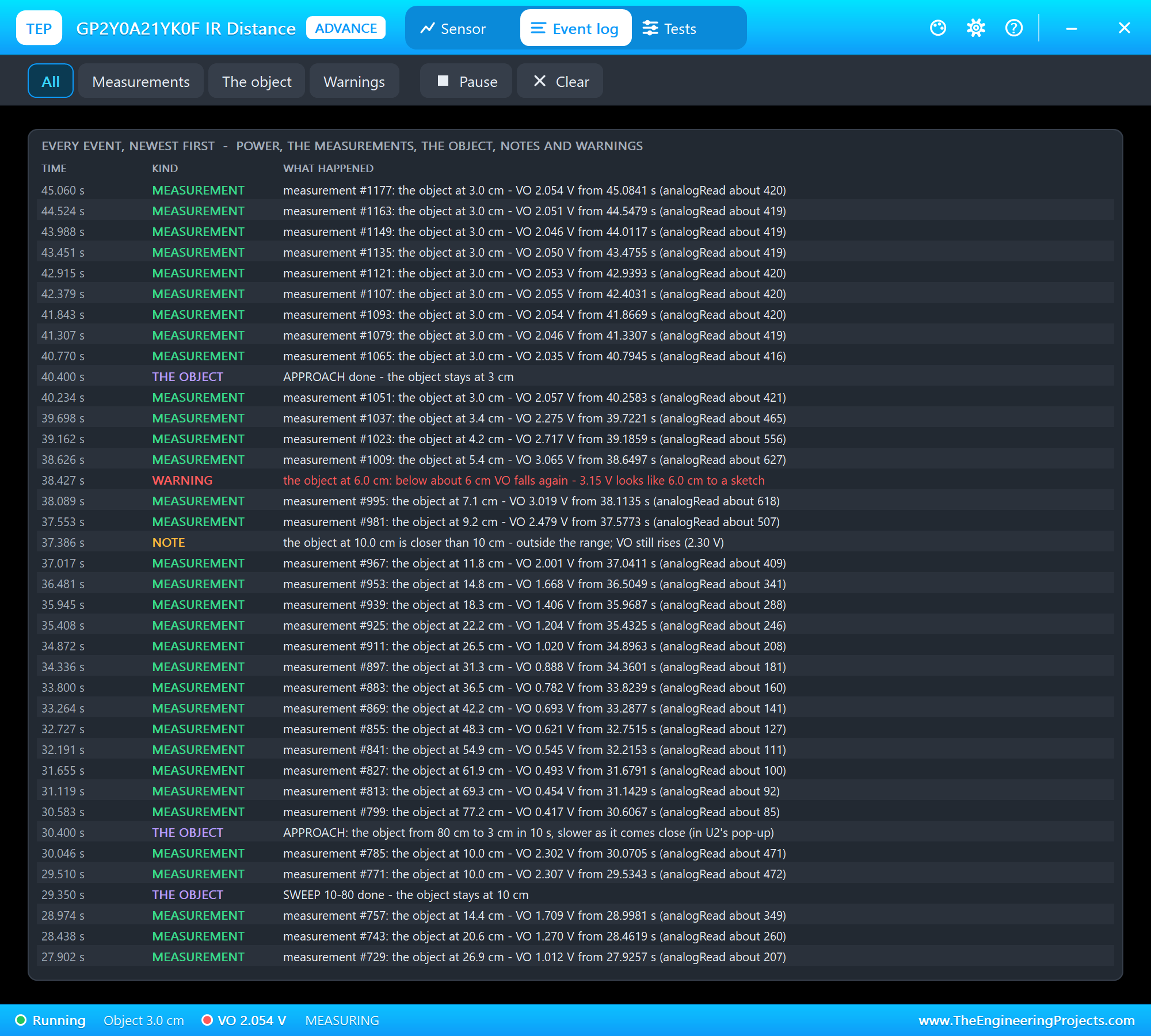
The Event log lists everything that happened, newest first: power, the measurements (two a second), the object and its motions, notes and warnings. Filter it by measurements, the object or warnings, pause it, or clear it.
The Simulation Log
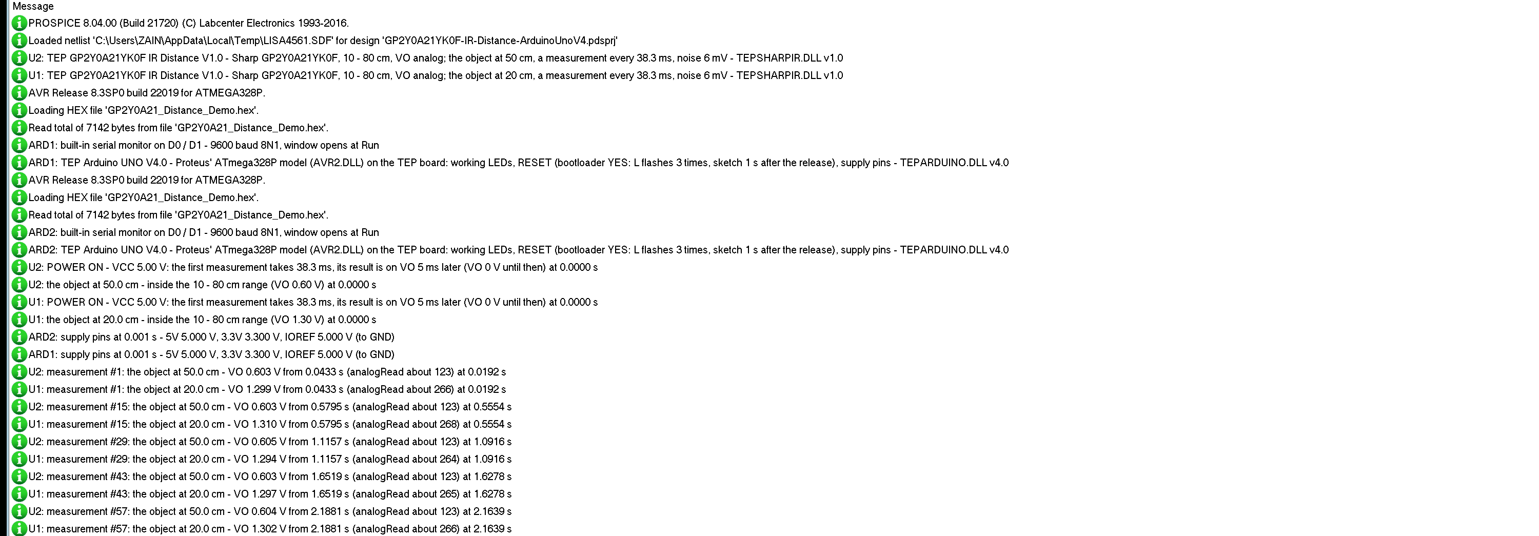
The sensors also write to the simulation log of Proteus, with the exact simulation time. This part shows node 1:
U1: TEP GP2Y0A21YK0F IR Distance V1.0 - Sharp GP2Y0A21YK0F, 10 - 80 cm, VO analog; the object at 20 cm, a measurement every 38.3 ms, noise 6 mV - TEPSHARPIR.DLL v1.0
U1: POWER ON - VCC 5.00 V: the first measurement takes 38.3 ms, its result is on VO 5 ms later (VO 0 V until then) at 0.0000 s
U1: the object at 20.0 cm - inside the 10 - 80 cm range (VO 1.30 V) at 0.0000 s
U1: measurement #1: the object at 20.0 cm - VO 1.299 V from 0.0433 s (analogRead about 266) at 0.0192 s
U1: measurement #15: the object at 20.0 cm - VO 1.310 V from 0.5795 s (analogRead about 268) at 0.5554 s
Measurement #1 is taken at 19.2 ms, the middle of the first cycle, and its result appears on VO at 43.3 ms. Every 0.5 s one measurement goes to the log; the Event log has them all.
How the Model Works
The sensor is an analog model. VCC and GND draw its 30 mA. VO is a voltage source behind 100 ohm, so the UNO's analog input reads it directly, just like the real output. Once per cycle the model takes the object's distance at that moment, looks it up on the curve and adds that measurement's noise; 5 ms after the cycle ends, VO jumps to the new value. Proteus solves the circuit at its own time points, so the model makes it place one on every change of VO - the steps are sharp, at the right time.
Troubleshooting
- A0 reads 0: no power on VCC and GND, or VO is not on the analog input; the PWR LED is off. In the first 43 ms after power-on VO is 0 V too.
- The distance grows when the object comes closer: it is closer than about 6 cm - keep objects 10 cm or more away.
- The reading jumps: take the median of a few readings, one per measuring cycle; on real hardware add the 10 uF capacitor.
- "nothing in range (beyond 80 cm)": VO is below 0.35 V - nothing within about 90 cm.
- VO lower than the curve: something loads VO - the Supply & wiring tool shows it.
- No part or no monitor: TEPSHARPIR.DLL or TEPARDUINO.DLL is missing from MODELS and the project folder; a closed monitor opens again with a click on the UNO's USB port.
Things to Know Before Using a Real GP2Y0A21YK0F
- Add a capacitor: 10 uF or more across VCC and GND, close to the sensor; the IR LED's current pulses put spikes on the supply and on VO.
- Mind the near side: nothing should come closer than 10 cm.
- Give it 5 V: 4.5 to 5.5 V; VO stays below about 3.2 V, so a 3.3 V board can read it if the sensor gets 5 V. To read it more finely, try our ADS1115 ADC Library for Proteus.
- Check the cable: the wire colours differ between sellers - go by the pin names.
- Surfaces: glass, mirrors and very dark or shiny objects can give wrong readings; strong sunlight can blind it.
Limitations of the Simulation
- Not modelled: the object's colour, material, size and angle (one typical curve), sunlight and other IR, the supply spikes of the IR LED (the current is the average), the part-to-part spread (the datasheet allows 0.25 to 0.55 V at 80 cm) and temperature. The near side below 6 cm and the tail past 80 cm follow the datasheet's graph only roughly.
- The LEDs, the badge, the panel button and the panels are TEP additions.
- The model is our own, written from the GP2Y0A21YK0F datasheet. This library is not made or endorsed by Sharp or Labcenter.
- Licences: the demo sketch needs no library. Its HEX file contains the Arduino AVR core 1.8.6 with LGPL-licensed code; the licence note and the source link are in the README.
- Tested in Proteus 8.5 in October 2026 (the demo as shipped on two Arduino UNO V4.0 boards with their built-in monitors: +, HAND, 3 cm and 20 cm on node 1 with the mouse, the red X and PANEL; 20 cm, RAW, 3 cm, NONE, SWEEP 10-80, APPROACH and the three tools on node 2; 81.7 s of simulation took 156 s, about 0.5 x real time with the pop-up and both monitors open). Proteus 7 is not supported.
So, that was all about the Sharp IR Distance Sensor Library for Proteus V1.0. I hope the curve, the measuring cycle and the too-close trap are clear now, and that your robot sees its walls from the first run. If you use the Sharp IR Distance Sensor Library for Proteus in a project, please share it in the comments or in our forum, and if you have any questions, ask in the comments and I will help you out. Till the next tutorial, take care and have fun!
Comments
0