


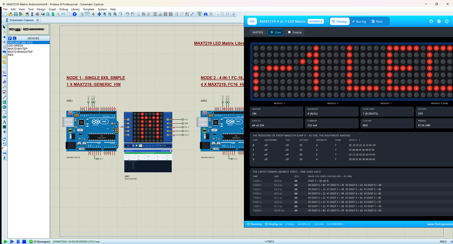
MAX7219 LED Matrix Library for Proteus V1.0 (8x8 and 4-in-1 FC-16)


Hello friends, I hope you all are doing great. Today, I am going to share the new MAX7219 LED Matrix Library for Proteus V1.0. The red 8x8 LED dot matrix with a MAX7219 behind it is the display that turns any Arduino project into a sign: scrolling names, clocks, counters, little animations. It comes as a single 8x8 module and as the long 4-in-1 FC-16 board with 32 x 8 LEDs, and both are now ready for your Proteus simulations, glowing LED by LED as the real ones do.
Behind every matrix sits our own model of the MAX7219, written from the Maxim datasheet: the 16-bit serial packets, the daisy chain through DOUT, the digit, intensity, scan-limit, shutdown and display-test registers, and the exact way each module wires its LEDs to the chip. You get four devices, the single and the 4-in-1 module, each as a Simple device with a live STATUS panel and an Advance device with a pop-up window and four test tools, and the demo runs the popular MD_Parola library on our Arduino UNO V4.0 with its serial monitor built into the board.
NOTICE: LED matrices look simple, but the questions we get are always the same: why is my text mirrored, why is one matrix dark, why does my Arduino reset when the whole display lights up? We built this model to show the answers on the screen: the module wiring, the chain and the current are all part of it, and we checked it pixel by pixel against MD_MAX72XX's own display buffer. It took our team a lot of hard work. Your feedback is the fuel that keeps us going, so please tell us what you think in the comments below or in the LCD Library board of our forum. And if our free libraries help you, you can buy us a coffee. So, let's get started with the MAX7219 LED Matrix Library for Proteus V1.0:
What is a MAX7219 LED Matrix Module?
The MAX7219 is an LED display driver from Maxim. It drives up to 64 LEDs, arranged as 8 "digits" of 8 "segments", by multiplexing them: one digit at a time, about 800 times a second, with a single resistor (RSET) setting the current of every segment. An Arduino talks to it over three wires, DIN, CLK and CS (called LOAD in the datasheet), and every message is a 16-bit packet: a register address and a data byte.
On an LED matrix module, the 8 digits and 8 segments simply become the rows and columns of an 8x8 grid of 3 mm LEDs. Two boards are everywhere:
| Single 8x8 module | 4-in-1 FC-16 module | |
|---|---|---|
| MAX7219 chips | 1 (the DIP chip under the matrix) | 4, in a daisy chain |
| LEDs | 8 x 8 = 64 | 32 x 8 = 256 |
| Board | about 50 x 32 mm | about 128 x 32 mm |
| Wiring (MD_MAX72XX name) | GENERIC_HW | FC16_HW |
| Headers | IN: VCC GND DIN CS CLK, OUT: VCC GND DOUT CS CLK | the same, at both ends |
| Devices in this library | MAX7219X1TEP / MAX7219X1ADVTEP | MAX7219X4TEP / MAX7219X4ADVTEP |
The MAX7219 Registers
| Address | Register | What it does |
|---|---|---|
| 0 | NO-OP | Nothing: lets a packet pass a chip in the chain |
| 1 - 8 | DIGIT 0 - 7 | The 8 LEDs (segments) of each digit, one bit each |
| 9 | DECODE MODE | Code B for 7-segment digits; 00 for a matrix |
| A | INTENSITY | 0 - 15: the duty from 1/32 to 31/32 |
| B | SCAN LIMIT | Digits 0 to n are shown; 7 shows all 8 |
| C | SHUTDOWN | 00 dark, 01 normal operation (the chip starts in shutdown) |
| F | DISPLAY TEST | 01 lights every LED at full duty, over everything else |
What's New in MAX7219 LED Matrix Library for Proteus V1.0
- Both popular modules: the single 8x8 module and the 4-in-1 FC-16, with their headers at both ends, drawn at 1.25 x their real size.
- Our MAX7219 model from the datasheet: 16-bit packets on DIN and CLK, latched by CS, every register, the power-up state and the daisy chain through DOUT.
- The module wiring: GENERIC_HW on the single module, FC16_HW on the 4-in-1, so a wrong hardware type in the sketch shows exactly as on a real board.
- Real brightness: each lit LED glows as bright as the intensity and the scan limit make it, in red, green, blue, yellow or white.
- The current estimate: what the LEDs draw from the supply, per chip and in total.
- Problems named on the panel: a dark matrix in shutdown, frames of the wrong size, display test, decode mode, a short scan limit.
- Four test tools on the Advance devices: Init check, Serial bus, Chain and Power.
- An MD_Parola demo on our Arduino UNO V4.0 with ten effects, a bouncing ball and commands that switch every register.
- A compact package: about 1.28 MB, without the C++ source code.
Four Devices: Single and 4-in-1, Simple and Advance
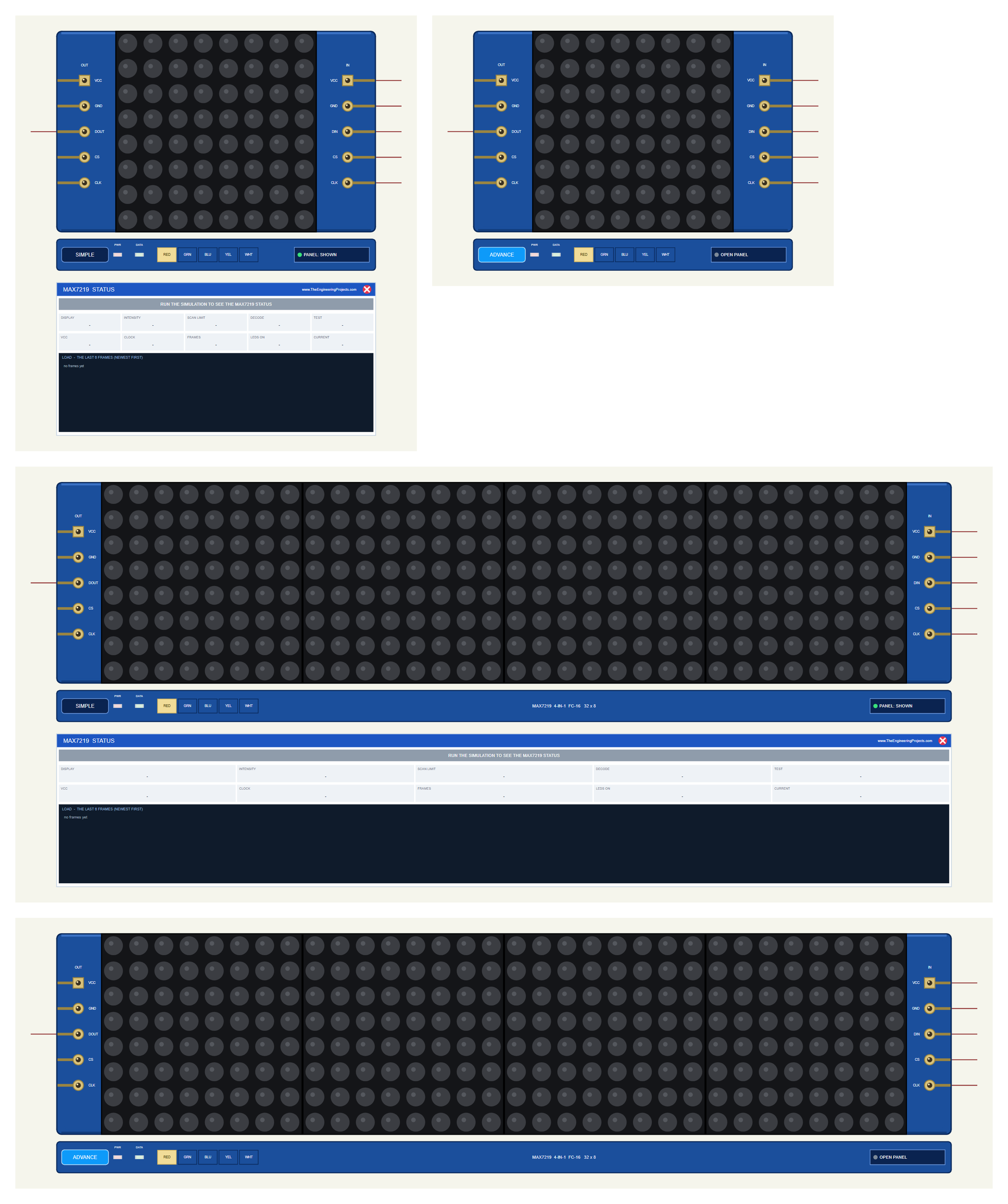
| Simple | Advance | |
|---|---|---|
| Single 8x8 | MAX7219X1TEP | MAX7219X1ADVTEP |
| 4-in-1 FC-16 | MAX7219X4TEP | MAX7219X4ADVTEP |
| On the schematic | The module + the MAX7219 STATUS panel | The module only |
| Status | Banner, 10 readouts, the last 6 frames | A pop-up window: Display, Bus log, Tests |
| Test tools | - | Init check, Serial bus, Chain, Power |
Download MAX7219 LED Matrix Library for Proteus
Click the button below to download MAX7219-LED-Matrix-Library-for-Proteus-v1.0.zip (about 1.28 MB, without the C++ source code):
MAX7219 LED Matrix Library for Proteus V1.0- README.txt: the devices, installation, the demo, wiring, chaining, the test tools and real hardware.
- Proteus Library Files:
TEPMAX7219.LIBandArduinoV4TEP.LIBfrom our Arduino Library for Proteus V4.0. - Proteus Model Files:
TEPMAX7219.DLLandTEPARDUINO.DLL. - Proteus Simulation:
MAX7219-Matrix-ArduinoUnoV4.pdsprj,MAX7219_Matrix_Demo.hexand copies of both DLLs. - Arduino Code:
MAX7219_Matrix_Demo.ino(needs "MD_Parola" and "MD_MAX72XX" from the Library Manager).
No Proteus yet? Read How to Download and Install Proteus 7 and 8. New to libraries? Follow How to Install a New Library in Proteus.
How to Install MAX7219 LED Matrix Library for Proteus
- Close Proteus and extract the whole zip file, for example to your Desktop.
- Copy the two files from Proteus Library Files into the LIBRARY folder of Proteus (usually
C:\Program Files (x86)\Labcenter Electronics\Proteus 8 Professional\LIBRARY). - Copy
TEPMAX7219.DLLandTEPARDUINO.DLLfrom Proteus Model Files into the MODELS folder. - Delete
TEPMAX7219.IDXfrom the LIBRARY folder if there is one. - Start Proteus, press P and search for MAX7219. Proteus's own MAX7219 chip shows up too; ours are the four modules.
Tip: keep the Proteus Simulation folder together, because the project needs its .hex file and the DLLs beside it. The library is tested in Proteus 8.5; Proteus 7 is not supported.
The MAX7219 Modules in Proteus
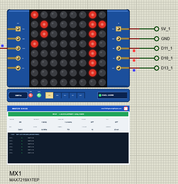
Each module is drawn at 1.25 x its real size, which keeps the 4-in-1 small enough to sit next to an Arduino UNO on one sheet. While the simulation runs, every LED of the matrix glows on its own. Under the board, a TEP strip holds the SIMPLE / ADVANCE badge, a PWR LED, a DATA LED that flashes on every LOAD, the LED COLOUR selector and the panel button. The strip, its LEDs and the panels are TEP additions; a real module has none of them.
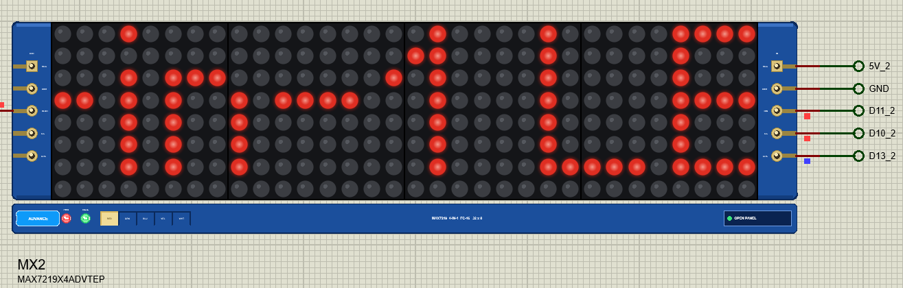
Pinout
| Pin | Function | Arduino UNO (demo) |
|---|---|---|
| VCC / GND | The 5 V supply (the MAX7219 runs from 4 - 5.5 V) | 5V / GND |
| DIN | Serial data in | D11 (MOSI) |
| CLK | Serial clock: DIN is read on its rising edge | D13 (SCK) |
| CS | LOAD: its rising edge latches the packets | D10 |
| DOUT (OUT header) | The data leaving the last chip, for the next module | open in the demo |
| Property | Values | What it does |
|---|---|---|
| PANEL | OPEN (default), CLOSED | Simple devices only: the STATUS panel at the start |
| COLOUR | RED (default), GREEN, BLUE, YELLOW, WHITE | The LED colour; the selector on the strip changes it at Run |
How the MAX7219 Takes Its Data
Every rising edge of CLK pushes the level of DIN into a 16-bit shift register, most significant bit first. When CS goes high, the chip latches the 16 bits: the address picks the register, the data byte fills it. On a MAX7219 the clocks shift in even while CS is high, so it is the rising edge of CS that matters.
In a chain, the bit that falls out of the first chip's register appears on its DOUT, 16 clocks after it went in, and enters the next chip. A frame for four chips is therefore 64 bits long, and the packet for the LAST chip is sent first. When CS rises, each chip keeps the 16 bits it holds, and a NO-OP packet leaves a chip as it was. MD_MAX72XX numbers the modules the same way: module 0 is the one at DIN, the right end of the display.
Chaining Modules in Proteus
To make a longer display, put the next module to the LEFT and wire its DIN to this module's DOUT. Only DOUT is a Proteus pin on the OUT header: on a real module VCC, GND, CS and CLK pass straight through, so in Proteus you wire the next module's VCC, GND, CS and CLK to the same nets. Then tell the sketch the total, for example 8 for two 4-in-1 modules.
GENERIC_HW or FC16_HW? The Hardware Type
There is no standard way to connect an 8x8 matrix to a MAX7219: one board wires the digits to the rows, another to the columns, and some mirror them. MD_MAX72XX therefore asks for the hardware type. The single DIP module is GENERIC_HW (digits on the columns, the columns reversed); the blue 4-in-1 is FC16_HW (digits on the rows). Our model is wired like the real boards, so a sketch with the wrong type gets the wrong picture:
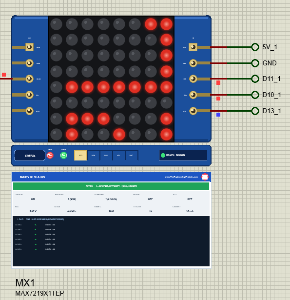
If your text is mirrored, upside down or turned on a real module, try the other types: PAROLA_HW, ICSTATION_HW and the DRxCRxRRx_HW names cover every combination.
The Module Count
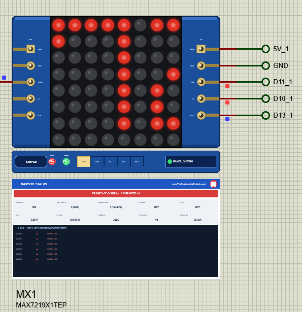
The number of devices in the sketch must match the chips in the chain. With 4 on a single module, every frame is 64 bits and the chip keeps only the last 16, which happen to be module 0's, so the picture still moves while the rest of the text disappears. The other way round, too few devices leave the far modules with stale or shifted packets.
Brightness, Scan Limit, Display Test and Shutdown
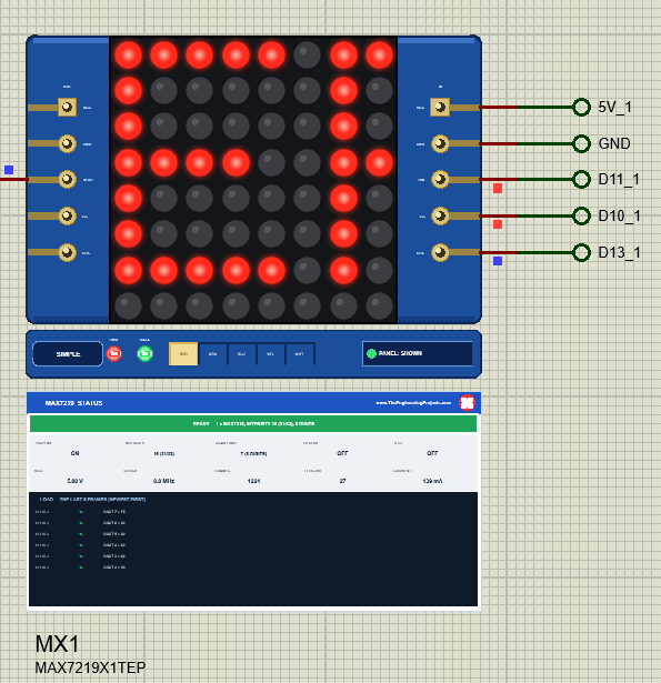
The INTENSITY register sets the duty cycle of the LEDs from 1/32 to 31/32 in 16 steps, and the model shows it the way the eye sees it: intensity 0 is dim but clearly visible, 15 is bright with a wide glow. MD_Parola's setIntensity() writes it to every chip:
intensity = constrain(atoi(arg), 0, 15); display().setIntensity(intensity);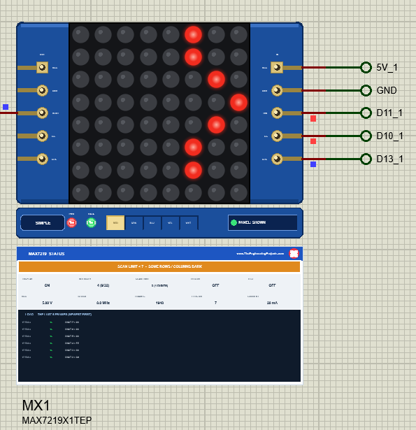
The SCAN LIMIT register decides how many digits the chip multiplexes. With fewer digits each one is on for a bigger share of the time, so it gets brighter and draws more current; that is why the datasheet warns against using it to blank part of a display. On a matrix it should always be 7:
matrix().control(0, last, MD_MAX72XX::SCANLIMIT, scanLimit);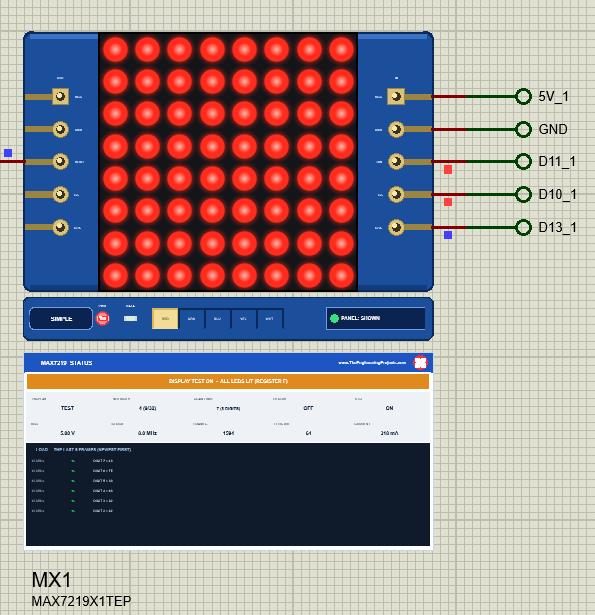
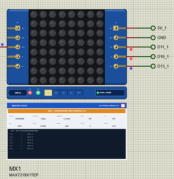
A MAX7219 wakes up in shutdown, so a matrix that stays dark after power-on usually means the sketch never wrote register C. MD_MAX72XX's begin() does it, and the demo can switch it back on purpose:
matrix().control(0, last, MD_MAX72XX::SHUTDOWN, sleeping ? MD_MAX72XX::ON : MD_MAX72XX::OFF);How Much Current Does a 4-in-1 Draw?
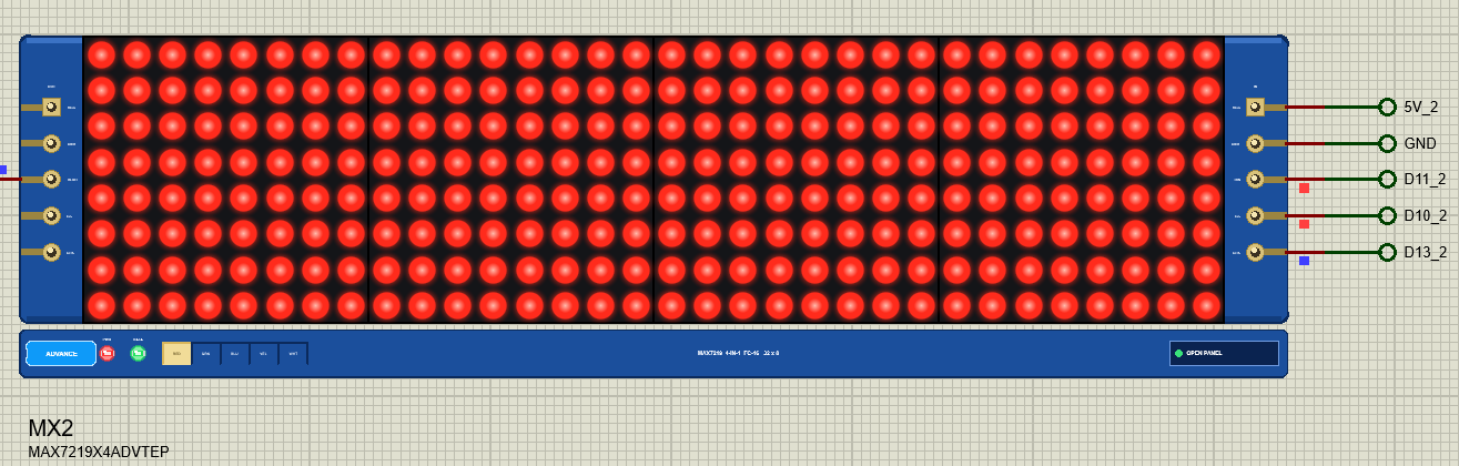
Each lit LED gets about 40 mA while its digit is on (RSET is 10 kohm on these modules), shared over the 8 digits. A full module at full duty therefore draws about 318 mA per chip, and the 4-in-1 about 1.27 A, more than twice what a USB port gives. The model adds it up from the registers and the Power tool shows it. On the bench, power a big display from a 5 V supply with a common GND, or keep the intensity low.
MAX7219 Simple: The STATUS Panel
Under the Simple devices a live MAX7219 STATUS panel shows the banner (READY, or the problem in amber or red), ten readouts - DISPLAY, INTENSITY, SCAN LIMIT, DECODE, TEST, VCC, CLOCK, FRAMES, LEDS ON and CURRENT - and the last six frames with their bits and packets. The red X closes the panel; PANEL on the strip opens it again.
MAX7219 Advance: The Pop-Up Window
The Display Page
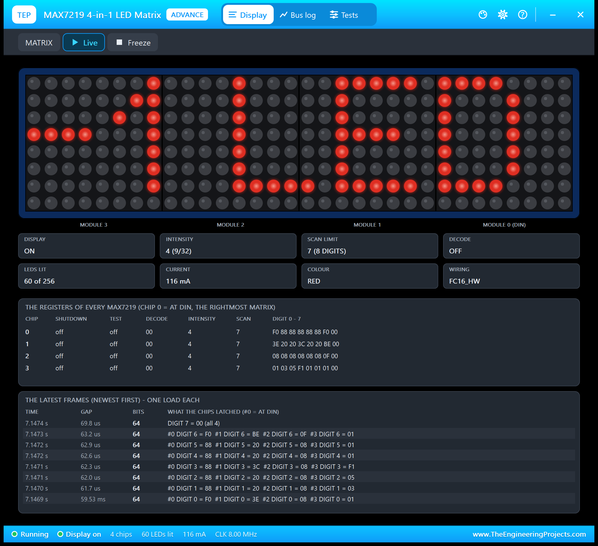
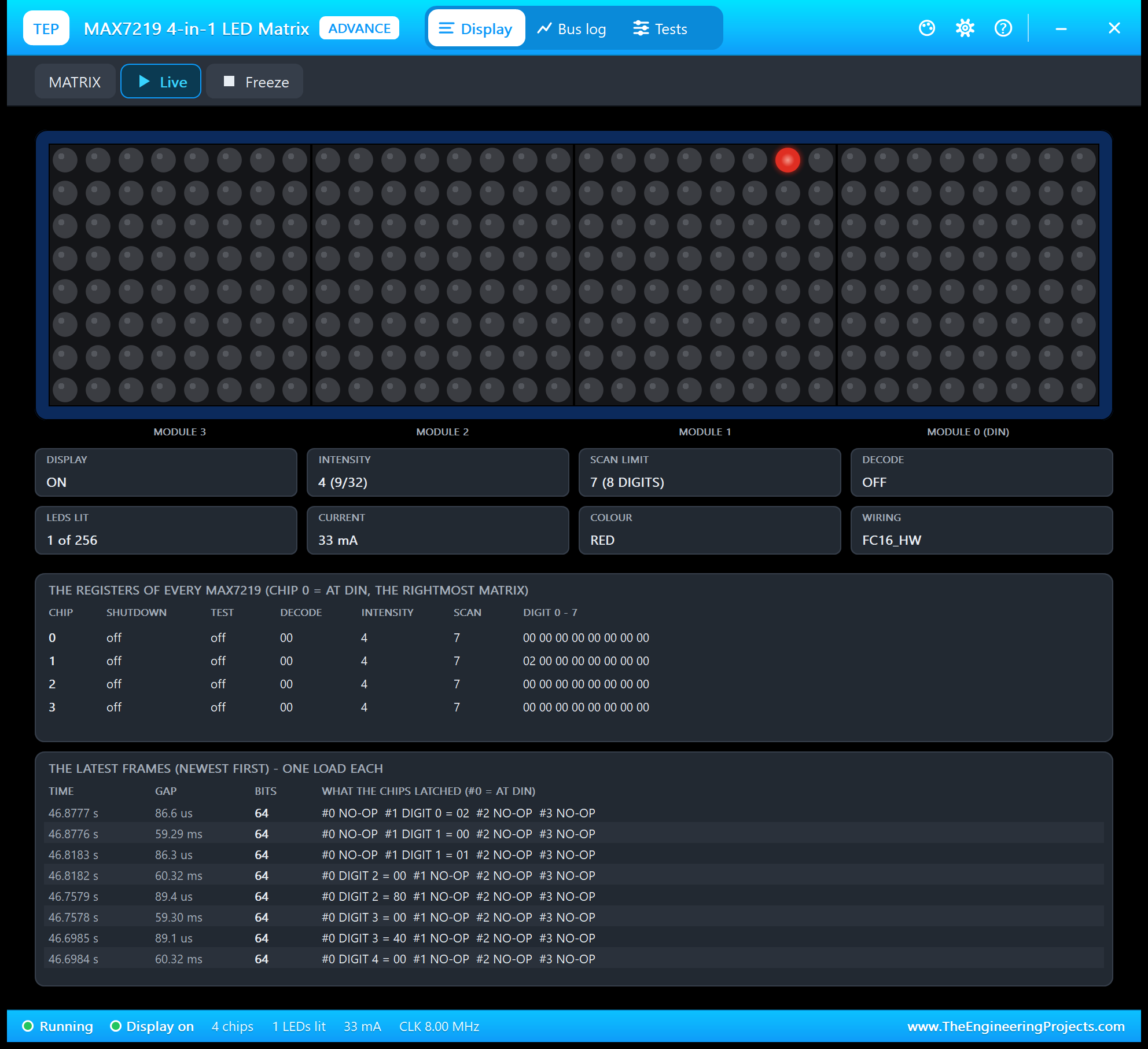
The tiles sum up the chain: display state, intensity, scan limit, decode mode, LEDs lit, current, colour and the wiring. The register table shows each chip's shutdown, test, decode, intensity, scan limit and its 8 digit bytes, so you can read the picture as the chips hold it.
The Bus Log Page
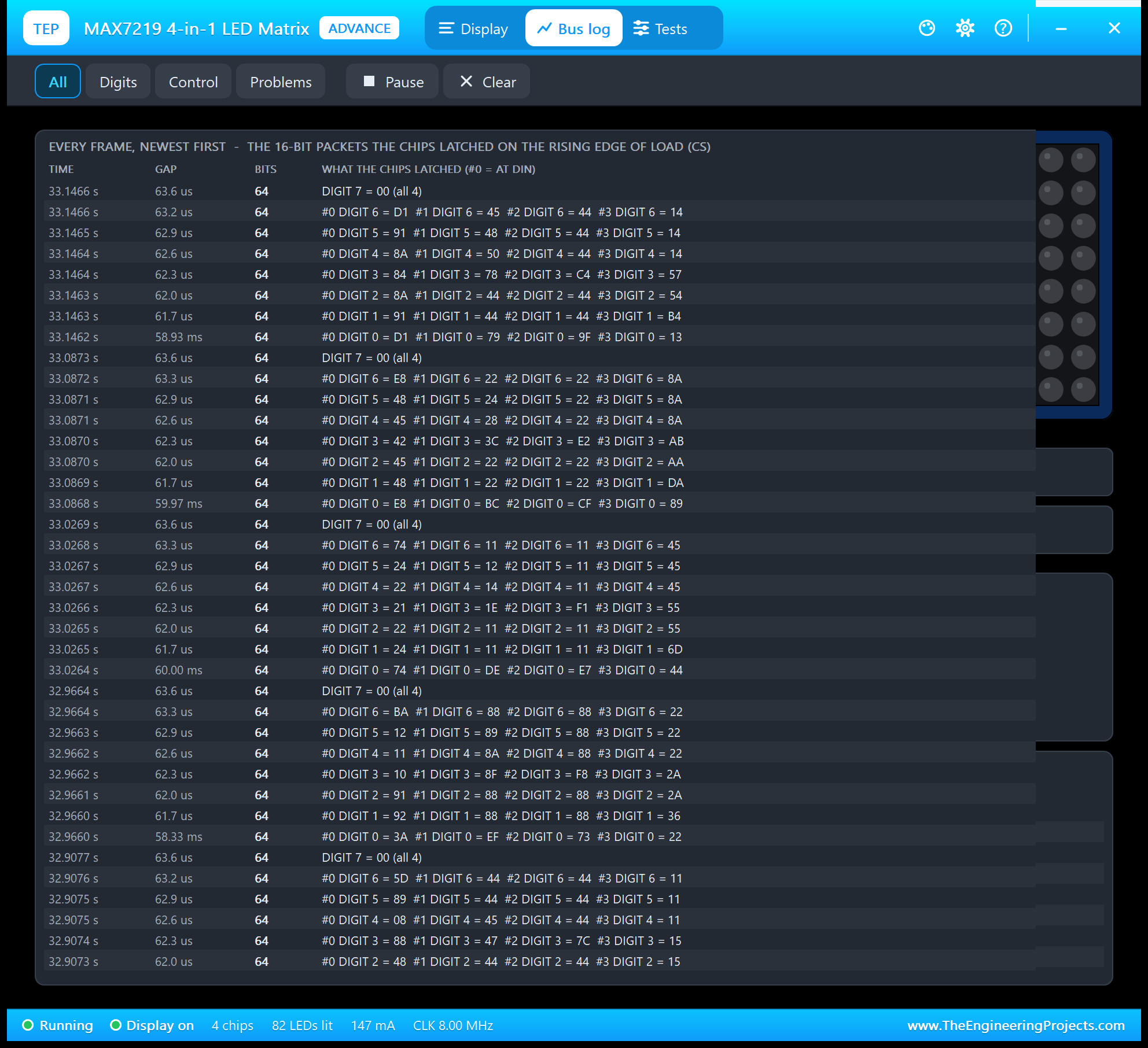
Filter it to the digit writes, the control registers or the problems only; Pause freezes the list.
Four Test Tools for the MAX7219
1. Init Check
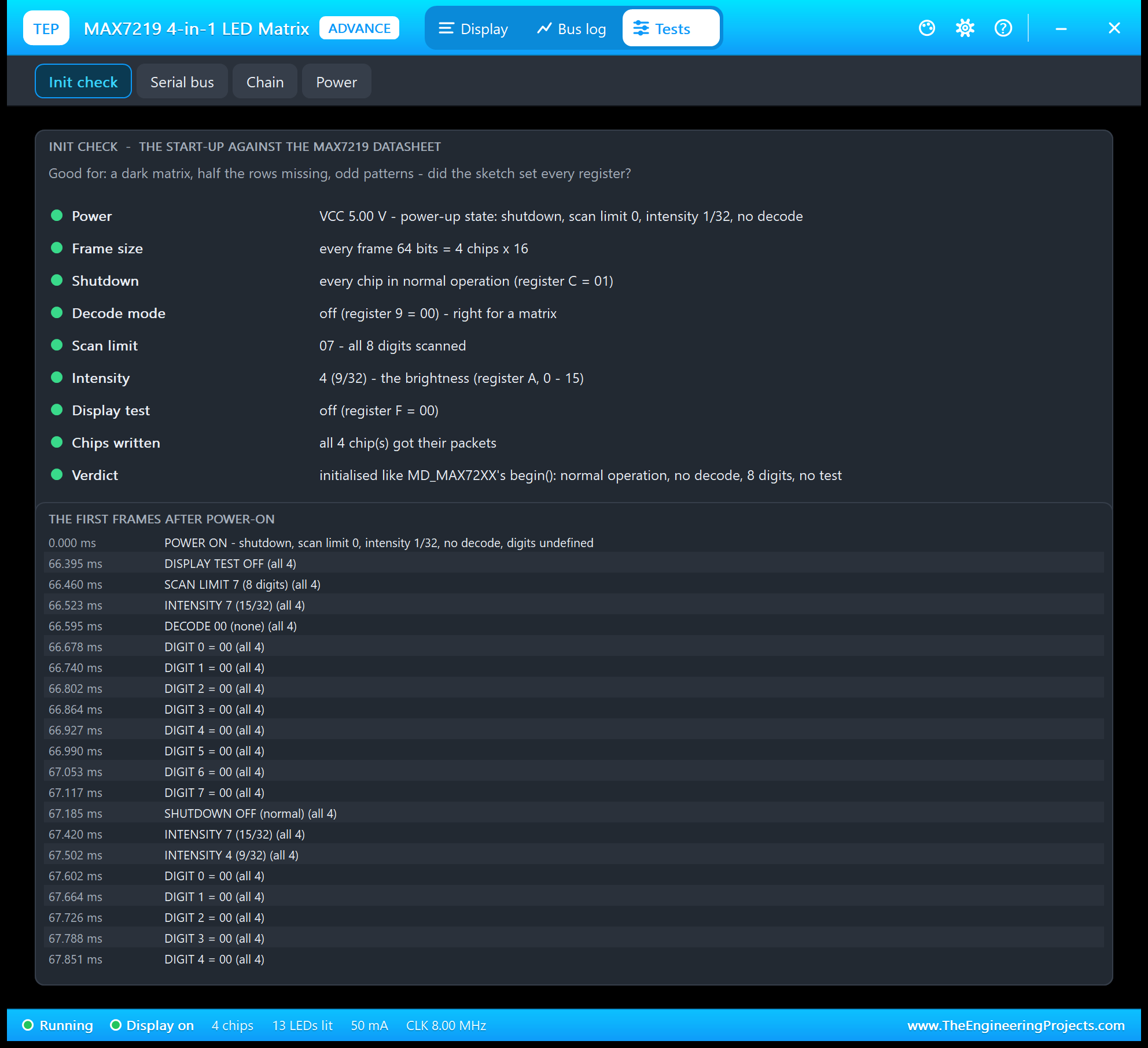
The start-up against the datasheet: the frame size, shutdown, decode mode, scan limit, intensity, display test and whether every chip got its packets, then the first frames as the sketch sent them - display test off, scan limit 7, intensity, decode 00, the 8 digits cleared and shutdown off.
2. Serial Bus
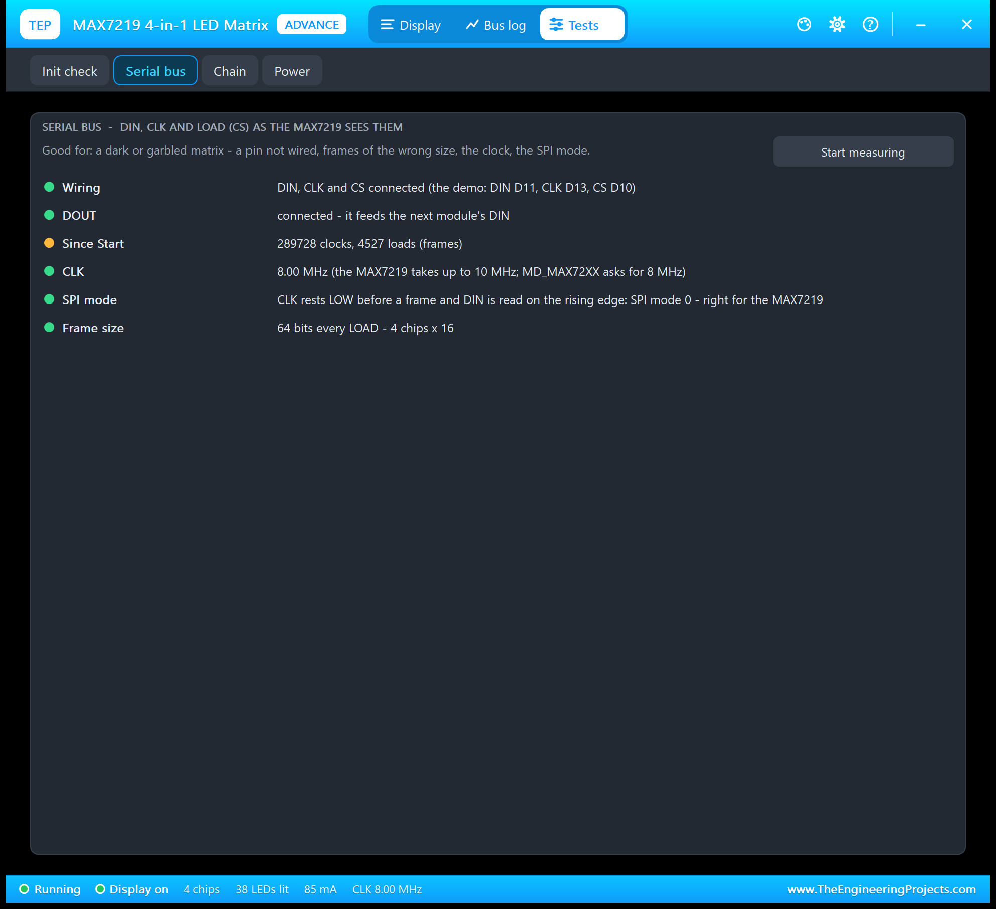
Good for a dark or garbled matrix: which pins are wired, the clocks and loads since Start, the clock against the MAX7219's 10 MHz, the SPI mode, frames of the wrong size, clocks with CS high and bits waiting for a LOAD.
3. Chain
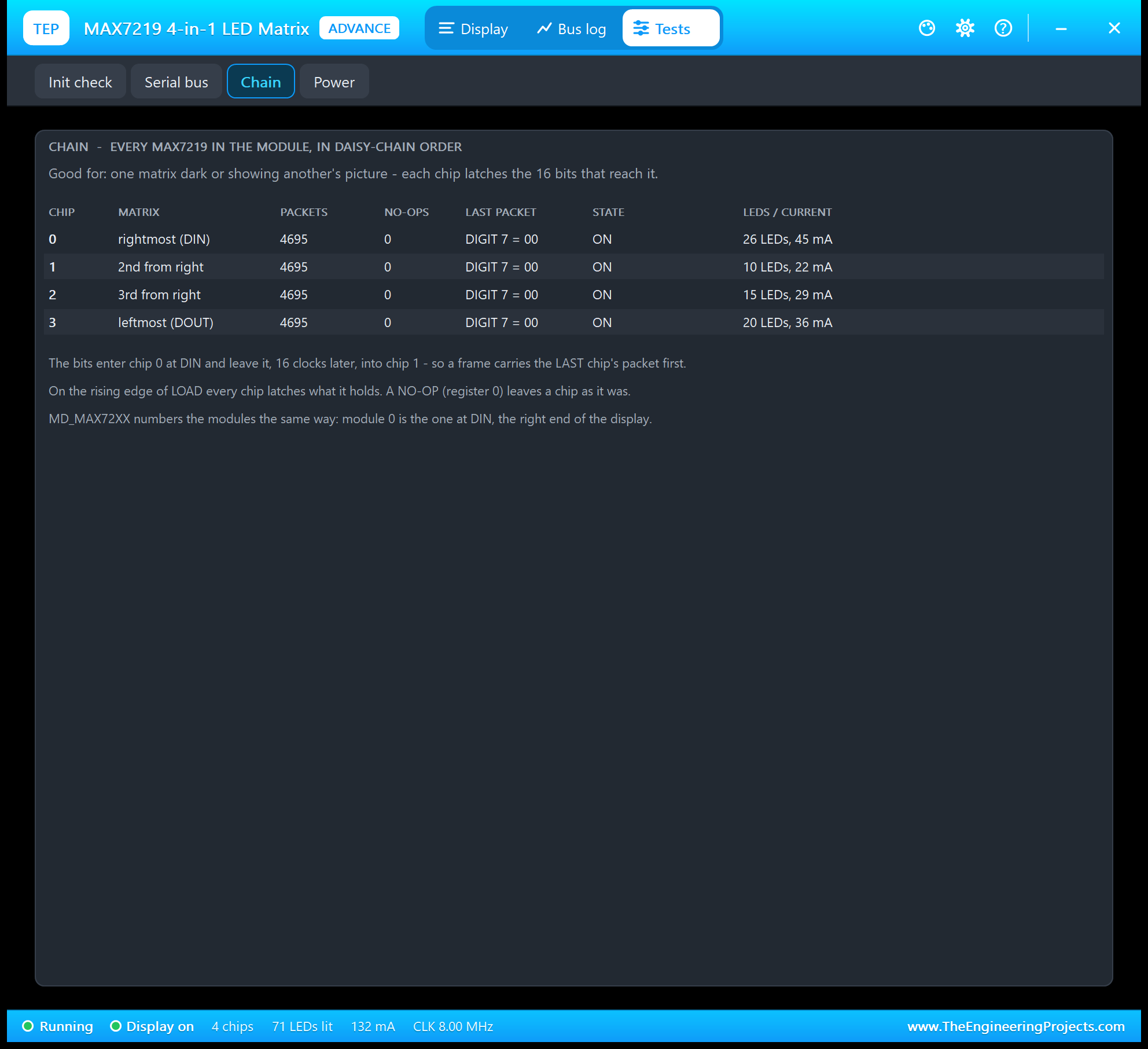
Good when one matrix is dark or shows another one's picture: each chip's packets and no-ops, its last packet, its state and the LEDs and current it drives.
4. Power
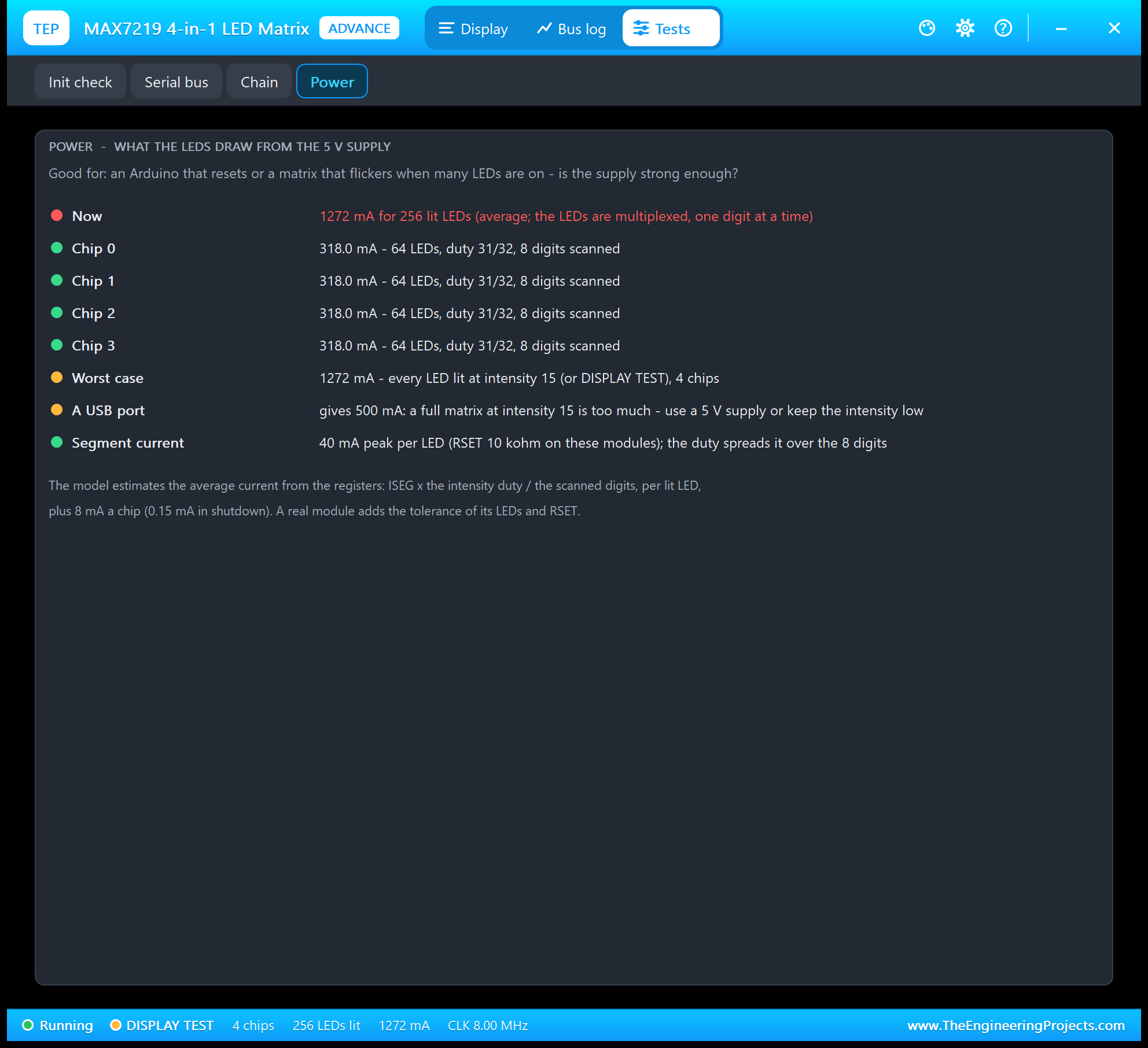
Good for an Arduino that resets or a matrix that flickers when many LEDs light up: the current now, per chip, the worst case for this module and a comparison with the 500 mA of a USB port.
MAX7219 LED Matrix with Arduino in Proteus
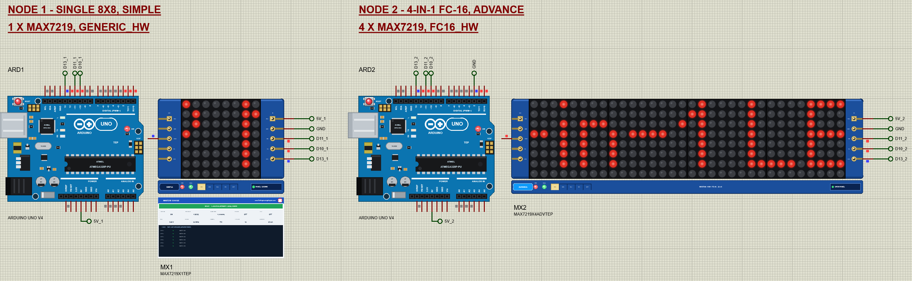
Open MAX7219-Matrix-ArduinoUnoV4.pdsprj. Two Arduino UNO V4.0 boards from our Arduino UNO Library for Proteus V4.0 run the same sketch: with D2 open it drives one module as GENERIC_HW, with D2 tied to GND (ARD2) four modules as FC16_HW. The monitors are built into the boards; our Introduction to Arduino UNO explains the pins.
Wiring
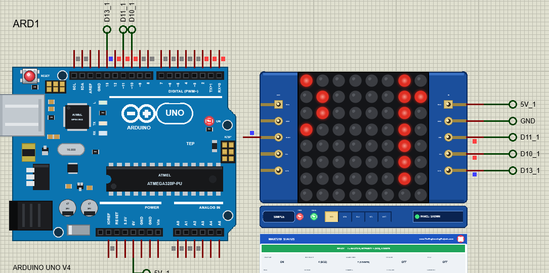
DIN goes to D11 and CLK to D13, the UNO's hardware SPI pins; CS can be any pin, the demo uses D10. VCC goes to 5V.
The Arduino Code
The sketch uses the MD_Parola library 3.7.7 and the MD_MAX72XX library 3.5.1:
#include <MD_Parola.h>
#include <MD_MAX72xx.h>
#include <SPI.h>
The display is made with the hardware type, CS and the number of modules:
parola = new MD_Parola(hw, CS_PIN, modules); // hardware SPI: DIN = D11, CLK = D13Two small helpers give the sketch the display and, through it, MD_MAX72XX's graphics object for the raw registers and pixels:
MD_Parola& display() { return *parola; }
MD_MAX72XX& matrix() { return *display().getGraphicObject(); }
D2 decides which module the sketch drives:
if (digitalRead(SIZE_PIN) == LOW) { hw = MD_MAX72XX::FC16_HW; modules = 4; strcpy(text, "TEP MAX7219 4-in-1 LED MATRIX"); }The text with an effect, and the loop that animates it:
void startText() {
  display().displayClear();
  display().displayText(text, PA_CENTER, speed, pauseMs, EFFECTS[effect], EFFECTS[effect]);
}
else if (display().displayAnimate()) display().displayReset();The ball uses MD_MAX72XX directly, one pixel at a time:
matrix().setPoint(ballR, ballC, false);To change the sketch, export a new HEX and load it into the UNO; see How to get the HEX file from Arduino. New to Arduino? Start with our Arduino Tutorial for Beginners.
Serial Monitor Commands
| Command | What it does |
|---|---|
| HELP / STATUS | The command list / the chips, type, mode, text, effect, intensity, scan limit, shutdown, test |
| TEXT <text> / EFFECT <name> | The text / LEFT RIGHT UP DOWN FADE OPEN BLINDS WIPE DISSOLVE PRINT |
| SPEED / PAUSE | The animation step and the pause (ms) |
| INTENSITY <0-15> / INVERT ON|OFF | The brightness / inverted text |
| BALL / SCROLL | A bouncing ball / the text again |
| SHUTDOWN ON|OFF, TEST ON|OFF, SCAN <0-7> | The MAX7219 registers directly |
| TYPE <type> / MODULES <1-8> | Make the display again with another hardware type / module count |
How to Run the Demo
- Press Run; move the monitor windows and MX2's pop-up aside.
- In ARD1's monitor type STATUS, TEXT Hello, EFFECT FADE, INTENSITY 15, TEST ON and TEST OFF.
- Try the mistakes: TYPE FC16 (then TYPE GENERIC) and MODULES 4 (then MODULES 1).
- On MX2 open Tests, type TEST ON in ARD2's monitor and look at Power.
MAX7219 LED Matrix Proteus Simulation Results
The Built-in Serial Monitor in Its Simple Interface
Each Arduino UNO V4.0 carries our TEP Serial Monitor Advance, wired inside the board to D0 / D1. The screenshots show its Simple interface (Ctrl+Shift+U; Esc for the full view). Read all about it in TEP Serial Monitor Advance for Proteus.
ARD1: STATUS
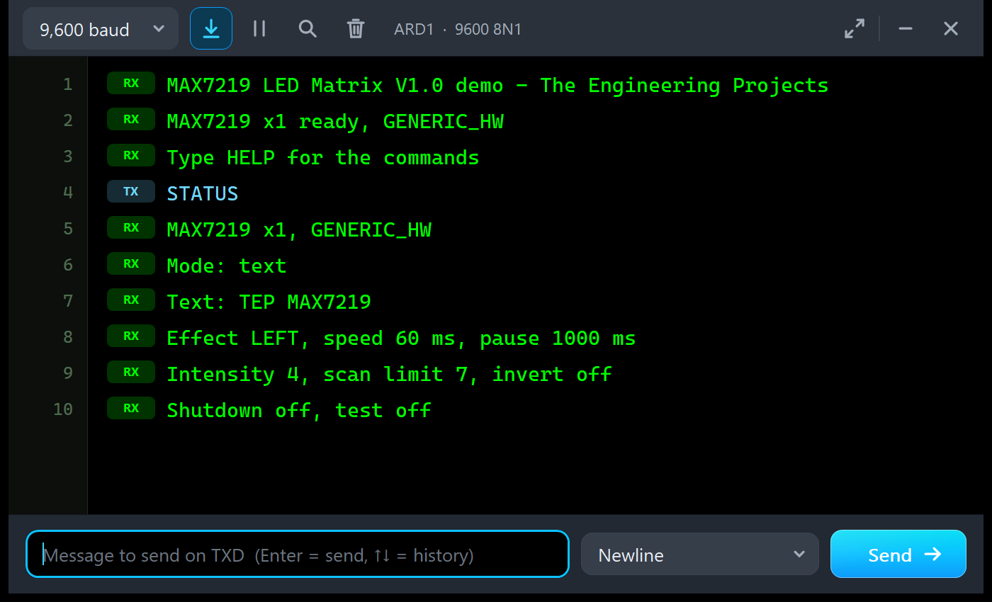
MAX7219 LED Matrix V1.0 demo - The Engineering Projects
MAX7219 x1 ready, GENERIC_HW
Type HELP for the commands
STATUS
MAX7219 x1, GENERIC_HW
Mode: text
Text: TEP MAX7219
Effect LEFT, speed 60 ms, pause 1000 ms
Intensity 4, scan limit 7, invert off
Shutdown off, test off
ARD1: The Registers and the Mistakes
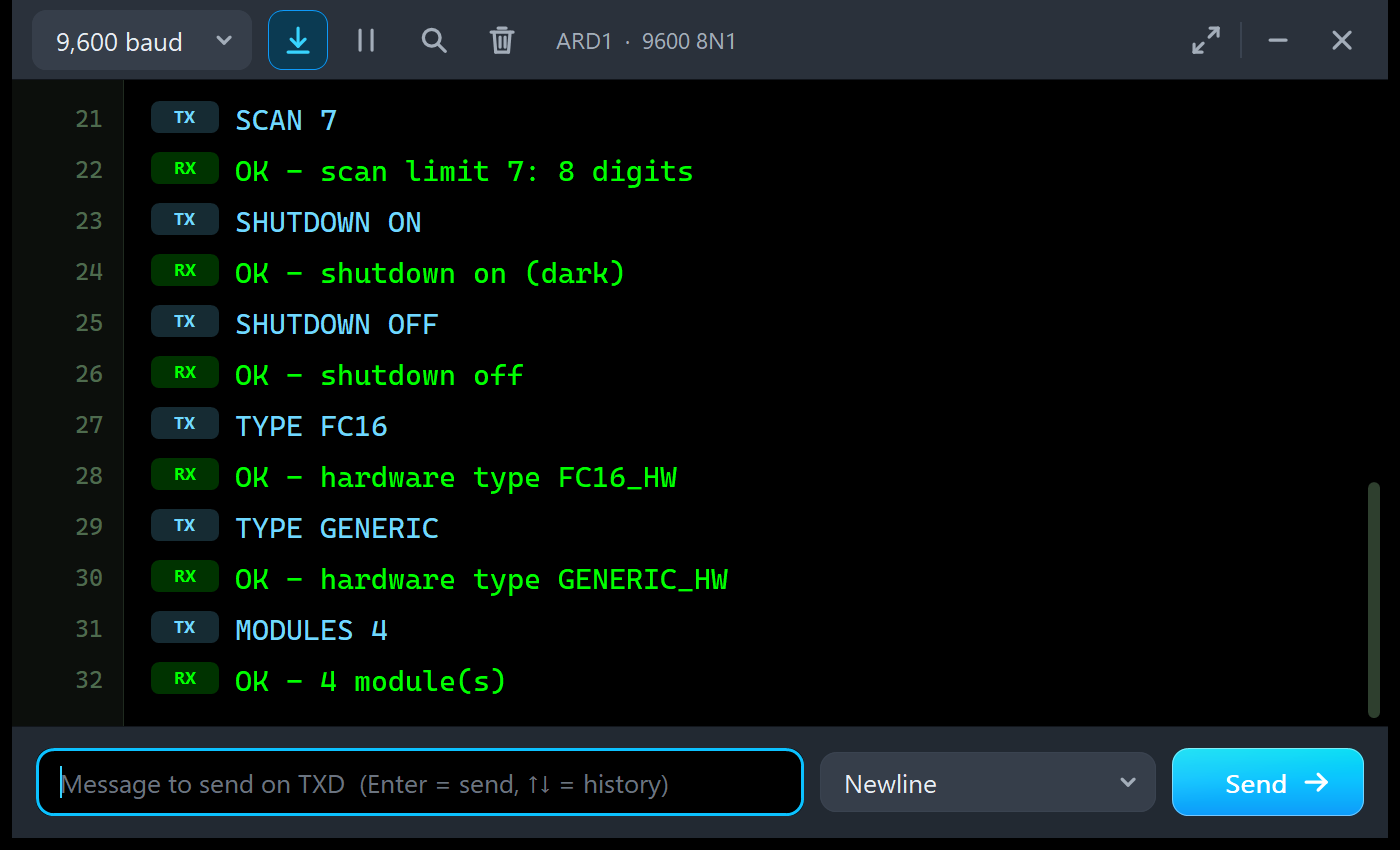
SCAN 7
OK - scan limit 7: 8 digits
SHUTDOWN ON
OK - shutdown on (dark)
SHUTDOWN OFF
OK - shutdown off
TYPE FC16
OK - hardware type FC16_HW
TYPE GENERIC
OK - hardware type GENERIC_HW
MODULES 4
OK - 4 module(s)
ARD2: The 4-in-1
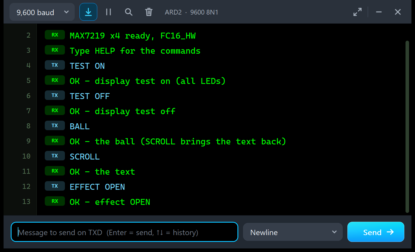
MAX7219 x4 ready, FC16_HW
Type HELP for the commands
TEST ON
OK - display test on (all LEDs)
TEST OFF
OK - display test off
BALL
OK - the ball (SCROLL brings the text back)
SCROLL
OK - the text
EFFECT OPEN
OK - effect OPEN
The Simulation Log
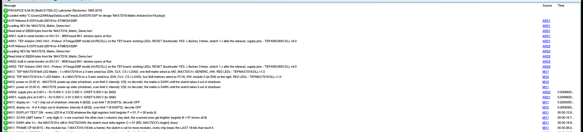
Each module writes a few lines to the simulation log: which board it is and how it is wired, the power-up state, the first picture with its intensity, scan limit and decode mode, and one line the first time each classic mistake happens. Nothing repeats, so the log stays readable in a long run.
Troubleshooting
- A dark matrix with the PWR LED off: no power - check VCC and GND.
- DARK - NOTHING ON THE BUS YET: check DIN on D11, CLK on D13 and CS on D10, and that the sketch calls
begin(). - DARK - SHUTDOWN MODE: the chip starts in shutdown;
begin()ends it. - FRAMES OF n BITS: the module count in the sketch does not match the chain.
- Mirrored, upside-down or turned text: the hardware type does not match the module.
- DISPLAY TEST ON / SCAN LIMIT < 7 / DECODE MODE ON: a register left in a test state.
- No part or no monitor: TEPMAX7219.DLL or TEPARDUINO.DLL is missing from MODELS and the project folder; a closed monitor opens again with a click on the UNO's USB port.
Things to Know Before Using a Real MAX7219 Module
- Power: a 4-in-1 can draw over 1 A; use a 5 V supply with a common GND for big displays.
- Logic level: at 5 V the MAX7219 wants 3.5 V for a high; a 5 V UNO is fine, a 3.3 V board may need a level shifter.
- Hardware type and module count: both go into the MD_Parola / MD_MAX72XX constructor.
- Chaining: modules are chained from right to left, DOUT into the next DIN.
- Memory: the demo needs 29,226 bytes of flash and 734 bytes of RAM; MD_Parola with its fonts is the bigger part.
Limitations of the Simulation
- Not modelled: the MAX7221 (its CS blocks the clock), the 800 Hz multiplex itself (the LEDs show the average), the 250 us to leave shutdown, the effect of RSET on the current, other module wirings such as PAROLA_HW or ICSTATION_HW boards, the limit of a real supply, and damage from a reversed supply.
- The strip, its LEDs and the panels are TEP additions.
- The model is our own, written from the MAX7219 datasheet; MAX7219 is a part of Maxim Integrated (Analog Devices). This library is not made or endorsed by Maxim, Analog Devices, majicDesigns or Labcenter.
- Licences: MD_Parola 3.7.7 and MD_MAX72XX 3.5.1 (LGPL-2.1) and the Arduino AVR core 1.8.6 with LGPL-licensed code are in the HEX file; the sketch is included so you can rebuild it with modified libraries.
- Tested in Proteus 8.5 in October 2026 (the demo as shipped on two Arduino UNO V4.0 boards with their built-in monitors: the scrolling text on both modules, STATUS, INTENSITY, TEST, SCAN, SHUTDOWN, TYPE, MODULES, BALL and an effect, the panel, the pop-up and the four tools; about 0.4 x real time with the pop-up and both monitors open). Proteus 7 is not supported.
Need a colour screen instead? Our ST7789 TFT LCD Library for Proteus V1.0 covers the 1.3" and 1.54" IPS TFTs and our TFT ST7735 Library for Proteus V1.0 the 1.8" TFT.
So, that was all about the MAX7219 LED Matrix Library for Proteus V1.0. I hope the packets, the chain, the hardware types and the current of a big display are clear now, so your scrolling sign works on the first real modules you plug in. If you use the MAX7219 LED Matrix Library for Proteus in a project, please share it in the comments or in our forum, and if you have any questions, ask in the comments and I will help you out. Till the next tutorial, take care and have fun!
Comments
0