


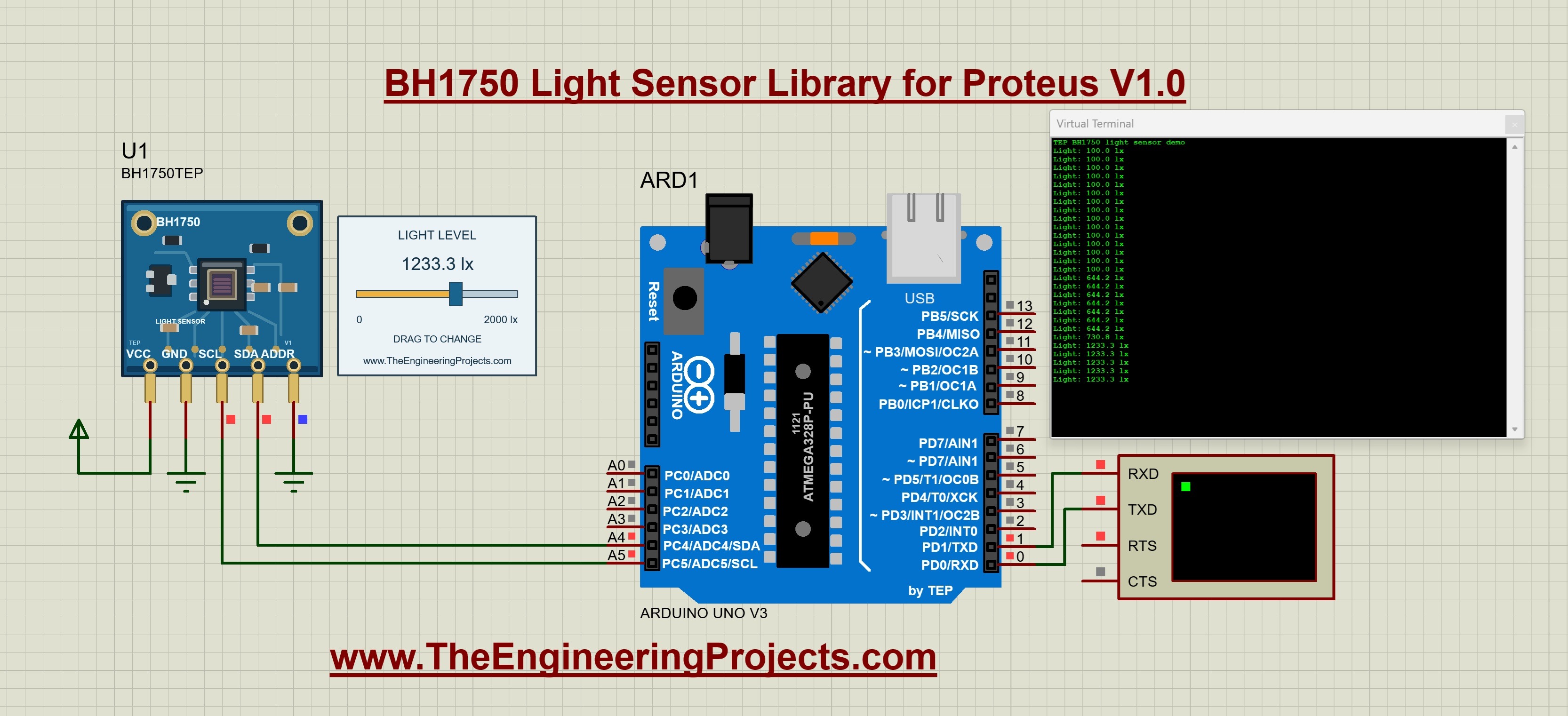
BH1750 Light Sensor Library for Proteus V1.0


Hello friends, I hope you are doing well. In today's tutorial, I am going to share our BH1750 Light Sensor Library for Proteus V1.0. With this library, we can connect a BH1750 light sensor to an Arduino Uno, change the simulated light level and display the readings on a Virtual Terminal. The sensor has an interactive slider, so you can test both bright and dark conditions while your Arduino program is running.
We will follow the same approach as our other Proteus library tutorials: first understand the sensor, download and install its files, check the connections, and then run a complete example. After that, we will look at the Arduino code and the calculations behind the lux readings. The download already includes the wired project and compiled HEX, so you can try the simulation before compiling anything yourself.
Our example uses the TEP Arduino UNO V3.0 at 16 MHz and was tested in Proteus 8.5 SP0. Once you have the basic circuit working, you can use it as the starting point for a light-controlled lamp, a brightness display or a data-logging exercise. Let us begin with what the sensor actually measures.
What Is the BH1750 Light Sensor?
The BH1750 is a digital ambient-light sensor. It measures illuminance, which describes the light arriving at a surface. We normally express this quantity in lux, written as lx. In our Proteus model, the slider supplies the simulated light input, and the Arduino receives the corresponding measurement through I2C.
This differs from connecting a light-dependent resistor to an analog input. An LDR circuit produces a voltage that your program must interpret. With the BH1750, the program requests a digital measurement and uses the sensor library to convert it into lux. We therefore need the correct communication pins and address, rather than an analogRead call.
A useful way to follow the experiment is to separate its three stages. The slider changes the light input, the sensor model responds to I2C requests, and the Arduino prints the result over its serial connection. If the address or wiring is wrong, moving the slider alone will not give the Arduino a valid reading.
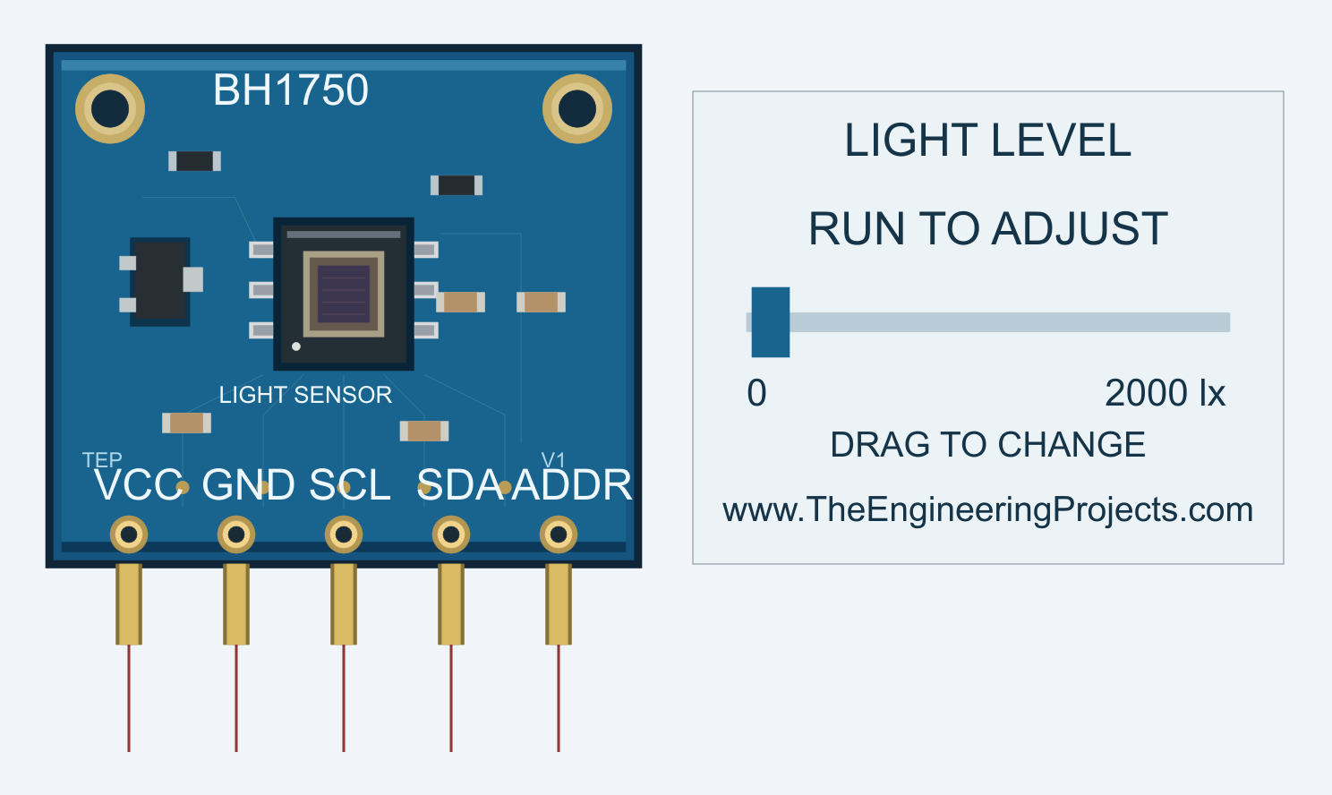
The component is called BH1750TEP in the Proteus device picker. Its light-control panel operates during simulation and defaults to a range of 0 to 2000 lux. These are simulated inputs: changing your room lighting or placing a lamp graphic beside the component does not alter the reading.
Download the BH1750 Library for Proteus
First of all, download the library package using the button below. Extract the complete ZIP into a normal folder before opening the project. Keep its folder structure together because the supplied circuit uses the firmware and model files stored beside it.
BH1750 Proteus Library and Arduino Simulation V1.0Inside the package, you will find the following folders. Each has a different purpose, so we will install the Proteus files first and leave the Arduino source files available for later.
| Folder | Files and purpose |
|---|---|
| Proteus Library Files | TEPBH1750.LIB, TEPBH1750.IDX, ArduinoV3TEP.LIB and ArduinoV3TEP.IDX add the sensor and Uno board to Proteus. |
| Proteus Model Files | TEPBH1750.DLL provides the functional light-sensor simulation. |
| Proteus Simulation | The wired BH1750-ArduinoUnoV3.pdsprj project, BH1750_Demo.hex and a local copy of the sensor DLL. |
| Arduino Code | The editable sketch, BH1750 programming library, AVR core source archive and firmware rebuild script. |
| Documentation | Installation instructions, test notes and notices for the included third-party software. |
The Proteus library and Arduino library are separate things. The LIB and IDX pair lets Proteus find and place the component. The DLL gives the sensor its simulation behavior. The Arduino BH1750 library supplies the C++ functions used by the sketch. Copying the Arduino library into the Proteus directory will not install the simulation model.
You also need a Proteus installation with AVR simulation support for the included Uno example. The connected project uses the Proteus 8 project format. Proteus 7 and other releases have not been verified for this package, so the walkthrough below describes the tested Proteus 8.5 configuration.
How to Install the BH1750 Sensor Library
Now let us add the sensor to Proteus. Save your current work and close the program before copying the files. This allows Proteus to load the new library when it starts again.
- Open the extracted Proteus Library Files folder.
- Copy
TEPBH1750.LIBandTEPBH1750.IDXinto the library directory configured for your Proteus installation. - Add
ArduinoV3TEP.LIBandArduinoV3TEP.IDXfrom the same folder if you do not already have the TEP Arduino UNO V3.0 library. - Open Proteus Model Files and copy
TEPBH1750.DLLinto your configured ProteusMODELSdirectory. - Restart Proteus and open the device picker, normally using the P button.
- Search for BH1750TEP, select it and place it on the schematic.
Library and model directory locations can vary between installations. Use the folders your copy of Proteus actually searches. Keep each LIB file with its matching IDX file, and avoid leaving several older BH1750 libraries in different search directories.
The example also includes a DLL beside its project. Keep that local copy in place when moving the simulation folder. The sensor uses this DLL model; it does not require you to load a sensor HEX file into its properties. BH1750_Demo.hex belongs to the Arduino's Program File property.
If a previously saved project still shows old artwork, restart Proteus and update its placed BH1750 instances from the installed library. A project can retain an earlier device definition even after the library files have changed. Check the pin endpoints again after updating the component.
The included Uno board is the one used in our Arduino Library for Proteus V3.0 tutorial. For your first test, use the supplied circuit so that the sensor, board and firmware match the example.
BH1750 Pinout and Arduino Uno Wiring
With the sensor in its default orientation, its five pins run from left to right as VCC, GND, SCL, SDA and ADDR. The labels are drawn on the blue board, while the electrical connection points extend below it. Start each wire at the exposed end of its pin.
| Sensor pin | Connect to | Function |
|---|---|---|
| VCC | Positive supply rail in the simulation | Powers the sensor model. |
| GND | Common ground | Provides a shared reference. |
| SCL | Arduino Uno A5 | Carries the I2C clock. |
| SDA | Arduino Uno A4 | Carries bidirectional I2C data. |
| ADDR | Ground | Selects the seven-bit address 0x23. |
Although A4 and A5 are also labeled as analog inputs, we use their I2C functions here. This mapping applies to the classic Uno used in this demonstration. If you change to another board, check its I2C pin assignments before copying the wiring.
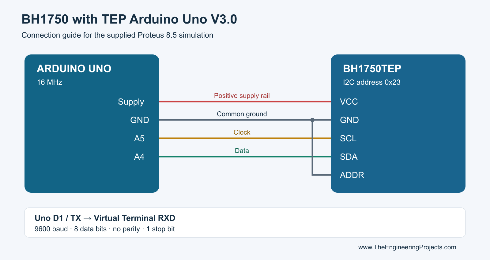
Connect Arduino D1/TX to RXD on the Virtual Terminal. The Arduino transmits the text, and the terminal receives it. The supplied circuit also has a return connection from terminal TXD to Arduino D0/RX, but this sketch does not require incoming serial commands.
Set the terminal to 9600 baud, eight data bits, no parity and one stop bit. These settings must agree with the firmware. A sensor can communicate correctly over I2C while the terminal still displays unreadable characters if the serial settings are wrong.
The included digital demonstration uses the AVR Wire implementation's enabled internal pull-ups. For a physical circuit, check the actual breakout's supply voltage, logic levels and pull-up requirements. The simulation does not establish suitable resistance, bus rise time or voltage compatibility for an unknown real module.
Run the BH1750 Simulation in Proteus
We are now ready to run the complete example. The screenshot below shows the circuit before simulation starts. The light panel displays RUN TO ADJUST; this is normal because the interactive control becomes active during the run.
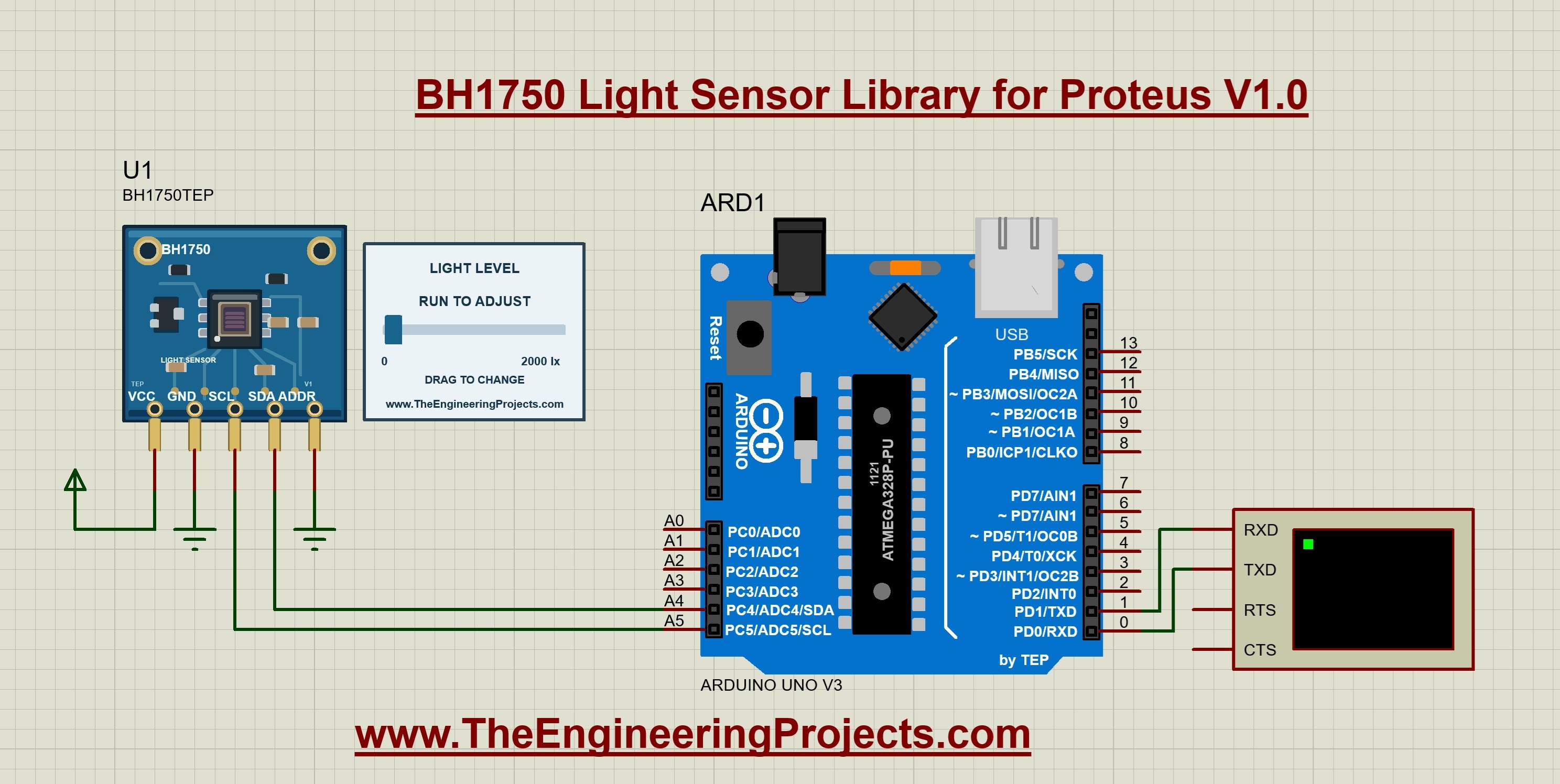
- Open
Proteus Simulation/BH1750-ArduinoUnoV3.pdsprjfrom the extracted download. - Keep
BH1750_Demo.hexandTEPBH1750.DLLbeside the project. - Double-click the Arduino and check that its Program File points to that HEX file.
- Confirm the Uno clock is 16 MHz and the Virtual Terminal uses 9600 baud.
- Press Run, then open the Virtual Terminal window if it is hidden.
After the startup message, you should see repeated lines reading Light: 100.0 lx. Let a few lines appear before moving the slider. This confirms that the firmware is running, the sensor initialization has succeeded and the serial connection is working.
Now drag the blue handle to change the light level. Moving left reduces the input, and moving right increases it. Pause briefly at each position so that the model can complete a measurement and the Arduino can print its next line.
In this running example, the panel is set to approximately 1233.3 lx, and the later terminal lines report the same rounded value. Earlier lines show the previous 100.0 lx starting point and intermediate readings. The terminal retains that history, which makes it useful for observing the response to your changes.
Keep the first experiment focused on the sensor and serial output. Once it responds correctly, save a separate copy before adding an LCD, relay or another device. You will then have a working reference circuit to return to if a later modification introduces a problem.
Arduino Code for the BH1750 Sensor
The existing example sketch is included below. It uses Wire for I2C communication and the claws BH1750 library to configure the sensor and convert its measurement into lux. The supplied firmware was built for the classic Arduino Uno with Arduino AVR core 1.8.6.
#include <Arduino.h>
#include <Wire.h>
#include <BH1750.h>

// Arduino Uno: SDA=A4, SCL=A5. Tie ADDR to GND for address 0x23.
// Set the Proteus terminal to 9600 baud, 8 data bits, no parity, 1 stop bit.
BH1750 lightMeter;
bool sensorReady = false;

void setup() {
  Serial.begin(9600);
  Wire.begin();
  Wire.setClock(100000);
  Wire.setWireTimeout(25000, true);
  sensorReady = lightMeter.begin(BH1750::CONTINUOUS_HIGH_RES_MODE, 0x23);
  Serial.println(F("TEP BH1750 light sensor demo"));
  if (!sensorReady) {
    Serial.println(F("Sensor not found: check VCC, GND, SDA, SCL and ADDR."));
  }
  delay(200);
}

void loop() {
  if (sensorReady) {
    const float lux = lightMeter.readLightLevel();
    if (lux >= 0) {
      Serial.print(F("Light: "));
      Serial.print(lux, 1);
      Serial.println(F(" lx"));
    } else {
      Serial.println(F("Read failed: check the I2C bus."));
    }
  }
  delay(500);
}
Understand the Initialization
Serial.begin(9600) starts the serial output at the same baud rate as the Virtual Terminal. Wire.begin() starts I2C, and Wire.setClock(100000) requests a 100 kHz clock. The timeout gives Wire a bounded wait if a transaction becomes stuck.
The next important call is lightMeter.begin(BH1750::CONTINUOUS_HIGH_RES_MODE, 0x23). It selects continuous high-resolution measurements and uses the address chosen by ADDR being connected to ground. The result is stored in sensorReady, so the program knows whether initialization succeeded.
If initialization fails, the sketch prints the connections to check. It does not keep retrying initialization in loop. After correcting the wiring or address, restart the simulation so that setup runs again.
Read and Print the Light Level
Inside loop, readLightLevel() obtains a reading. A nonnegative value is printed with one decimal place and the unit lx. A negative return produces a read-error message instead of being displayed as a real negative light level.
The 500 ms delay makes the sketch print approximately twice per second, with some additional execution time. Printing one decimal place does not give the sensor an accuracy of 0.1 lux. Display formatting, digital resolution and physical measurement accuracy are different properties.
Compile the Sketch After Making Changes
- Open
Arduino Code/BH1750_Demo/BH1750_Demo.inoin Arduino IDE. - Select Arduino Uno and use the documented Arduino AVR Boards 1.8.6 core for the same build environment.
- Install the supplied BH1750 library from
Arduino Code/librariesinto your sketchbook's libraries folder. - Compile the sketch and export the compiled application binary.
- Select the resulting application HEX in the Uno's Program File property, then restart the simulation.
If your Wire library does not provide setWireTimeout(), check the board package and core version before changing the example. The download also includes an AVR core source archive and a standalone rebuild script. Its installation notes explain the compiler and core paths required by that route.
How the Light Slider and Sensor Properties Work
The slider changes the simulated illuminance supplied to the sensor model. It does not write numbers directly into the terminal. Your sketch still has to configure the sensor, request data over I2C and print the returned measurement.
| Property | Initial setting | Effect |
|---|---|---|
| Illuminance, LUX | 100 lux | Sets the light input at the start of a run. |
| Illuminance after step, LUX2 | 1000 lux | Sets the target for an optional timed change. |
| Light step time, STEP_TIME | 0 seconds | Zero disables the timed change. |
| Slider maximum, LUX_MAX | 2000 lux | Sets the right-hand end of the interactive range. |
During a run, drag the blue handle or click its track. Clicking the board artwork does not change the light level. To enter an exact starting value or change the maximum, stop the simulation, edit the component properties and restart.
For an automatic test, use LUX = 100, LUX2 = 1000 and STEP_TIME = 3. Leave the slider untouched after starting. The light input changes at three seconds of simulation time, and the new terminal reading appears after the measurement and printing delays.
A manual slider action overrides the timed input for the rest of that run. Stop and restart to repeat the configured sequence. Simulation time can differ from wall-clock time when Proteus is paused or running slowly, so use the simulation clock when interpreting this test.
The NAME, VERSION and Designed by fields identify the component and are read-only. They are separate from the editable light settings. Restarting returns to the configured initial light input; a previous drag does not permanently rewrite the Illuminance property.
Understand the Lux Calculation
Let us look at why the slider and terminal can sometimes differ slightly. The model returns a two-byte integer measurement, while the panel can display a fractional light input. With the example's high-resolution mode and default measurement-time value of 69, the library converts the raw value using:
Illuminance in lux = raw measurement / 1.2
If the two received bytes are called MSB and LSB, the combined value is raw measurement = 256 × MSB + LSB. For example, bytes 0x00 and 0x78 represent decimal 120, which gives 120 / 1.2 = 100 lux. The BH1750 library performs this decoding for us.
Our model converts the requested light input back into an integer count. At an input of 991.1 lux, 991.1 × 1.2 gives 1189.32, which rounds to 1189 counts. Decoding 1189 / 1.2 gives approximately 990.83 lux, printed as 990.8 lx. This explains the small difference recorded in the development tests.
The formula above applies to the example settings. Changing the measurement-time register or using the alternative high-resolution mode changes the scaling, and the library accounts for that. Do not apply another division by 1.2 to readLightLevel(), because that function already returns lux.
Measurement Time and Display Updates
The functional model uses a 120 ms conversion period for the default high-resolution setting. Its low-resolution setting uses 16 ms, and changing the measurement-time value scales the modeled period. These are model timings, not a new measurement of a physical sensor.
Our example prints more slowly because of its 500 ms loop delay. You should therefore expect a short delay between moving the slider and seeing the new line. Reducing the printing delay cannot make a sensor conversion finish earlier, and repeatedly reading a result can return the same completed measurement.
Test the Circuit with Repeatable Light Levels
Once the first reading appears, check more than one light level. A small sequence of predictable tests is more useful than dragging randomly and trying to remember what changed.
- Start with the supplied settings and confirm repeated readings around 100.0 lx.
- Drag fully left and wait for the terminal to show 0.0 lx.
- Drag fully right and confirm the default upper endpoint of 2000.0 lx.
- Choose an intermediate position and compare the panel and terminal, allowing for integer conversion and rounding.
- Stop and restart, then confirm the configured 100 lux starting value returns.
- Enable the optional three-second 100-to-1000-lux step and repeat the run without touching the slider.
The development notes record the endpoint, intermediate and timed-step checks with the TEP Uno in Proteus 8.5. Those results describe the supplied demonstration. A different microcontroller, firmware library or Proteus version needs its own check.
Try an Automatic-Lighting Exercise
As a next step, print a message when the reading falls below 200 lux. Then add a separate switch-off threshold above 300 lux. Between those thresholds, keep the previous state. This introduces hysteresis and avoids repeatedly changing state around a single boundary.
The separation in this example is 300 - 200 = 100 lux. Test below 200, above 300 and within the middle band. Also decide what should happen at exactly 200 and 300. These are teaching values; choose thresholds for your real application based on its requirements.
Common Problems and Their Solutions
| Problem | What to check |
|---|---|
| BH1750TEP does not appear in Pick Devices. | Check the active library directory, the LIB/IDX pair and the exact device name. Restart Proteus after copying the files. |
| The drawing appears, but the model cannot load. | Check TEPBH1750.DLL in MODELS and beside the supplied project. The DLL and device library have different jobs. |
| The Virtual Terminal is blank. | Check Run, the Arduino HEX path, the 16 MHz clock and D1/TX to terminal RXD. Open the instrument window if it is hidden. |
| The terminal displays unreadable characters. | Match its baud rate to Serial.begin(9600), then check the clock and eight-data-bit, no-parity, one-stop-bit format. |
| The sketch reports Sensor not found. | Check VCC, ground, SDA/A4, SCL/A5 and ADDR/GND. Correct the problem and restart so setup runs again. |
| The panel says RUN TO ADJUST. | Start the simulation before using the slider. |
| The panel changes, but the terminal remains fixed. | Allow several print intervals, inspect read-error messages and confirm that the intended HEX is loaded. |
| The program ignores your source-code changes. | Recompile and select the new HEX. Editing the INO file alone does not update the running firmware. |
| The input changes unexpectedly during a run. | Check STEP_TIME. Set it to zero for a manual-only test. |
If you still have a problem, return to the original circuit and change one setting at a time. When asking for help, include the Proteus version, the selected address, the terminal message and a screenshot of the connections. Those details help identify whether the issue is installation, communication or application code.
Practical Review of the BH1750 Library
The useful part of this model is that we can supply a repeatable light input while firmware communicates through I2C. The included project and HEX make the first experiment straightforward, and the source code lets us develop the example further. Manual and timed inputs give us two ways to test the same program.
Use the simulation for address selection, unit conversion, serial displays and threshold logic. It does not reproduce optical geometry, room lighting, real sensor tolerances, analog noise or physical bus behavior. The default 2000 lux slider maximum is an adjustable control setting, not a specification of the physical sensor's complete measurement range.
Frequently Asked Questions
Does the Download Include the Arduino Uno Library?
Yes. The package includes the TEP Arduino UNO V3.0 LIB and IDX files used by the supplied project. It also includes the BH1750 programming library for rebuilding the sketch. Install the Proteus files in Proteus and the programming library in your Arduino sketchbook's libraries folder.
Do I Need a HEX File for the Sensor?
The sensor uses TEPBH1750.DLL. Load BH1750_Demo.hex into the Arduino's Program File property. This distinction matters if you have used older sensor libraries that placed a separate HEX inside the sensor component.
Can I Use Address 0x5C?
The model supports 0x5C when ADDR is high and 0x23 when ADDR is low. Change both the connection and the sketch address together. The walkthrough uses 0x23; the alternate address has automated core coverage rather than a separately demonstrated circuit in this tutorial.
Can I Connect Another Microcontroller?
Another controller needs compatible I2C transactions, suitable simulated pins and its own firmware. The included HEX targets the Uno's ATmega328P and cannot be reused on an unrelated processor. Begin with the supplied example, then verify your port independently.
Why Do Readings Return to 100 Lux After Restarting?
Restarting restores the Illuminance property. The slider changes the input during a run without permanently changing that saved property. Edit Illuminance before starting if you want a different initial condition.
Does This Library Work in Proteus 7?
The completed demonstration was tested in Proteus 8.5 SP0. Proteus 7 compatibility is not established, and the packaged circuit uses the Proteus 8 project format. A recognized library filename alone does not prove that the model and interactive controls will work in another version.
That completes our BH1750 Light Sensor Library for Proteus tutorial. Install the files, run the supplied Uno example and confirm the light readings before building your own application. Try the slider and timed-step exercises, then share your results and questions in the comments.
Comments
0