


Wind Turbine Generator Library for Proteus V1.0 (Arduino + 12V)


Hello friends, I hope you all are doing great. Today, I am going to share the new Wind Turbine Generator Library for Proteus V1.0. Small wind turbines are everywhere in renewable energy projects: on rooftops and boats, in school science fairs and on the bench next to an Arduino that logs how much power they make. The common hobby type is a 12 V DC wind turbine: three blades on a hub, a permanent-magnet DC generator behind them and two wires down the tower. The wind turns the blades, the blades turn the generator, and the generator gives a voltage that climbs with the wind.
Wind Turbine Generator Library for Proteus
Latest version: V1.0 (November 2026, this tutorial)
Helping Tools
- Serial Monitor Advance: a serial terminal window for the UART of your board
- Serial Monitor Expert: the serial monitor with extra debugging tools
- LCD Library for Proteus V3.0: 16x2, 20x4 and I2C LCDs to show your readings
This library puts such a turbine into Proteus as a part of its own. Its generator is in the circuit with its EMF, its winding resistance and its inductance, and its current brakes the rotor, so the load you connect really changes how fast it turns. The wind comes from a property, from wind buttons on its pop-up during the simulation, or from a built-in demo profile that goes from calm to a strong wind and back. The pop-up shows the rotor, the tip speed ratio, the power curve and the reason when the turbine stalls or runs away. The demo reads it from an Arduino UNO V4.0 and switches a load with our relay module.
NOTICE: a wind turbine on a schematic is usually a battery symbol with a fancy name. Our team put a lot of effort into building one that behaves like the real thing: it needs a breeze to start, it slows down when you load it, it gives its best power only at the right speed, and it runs away when you leave it without a load in a strong wind. Your feedback is the fuel that keeps us going, so please tell us what you think in the comments below or in the Motor Driver board of our forum. And if our free libraries help you, you can buy us a coffee. So, let's get started with the Wind Turbine Generator Library for Proteus V1.0:
What is a Wind Turbine Generator?
A wind turbine generator turns the energy of moving air into electricity in two steps. The rotor - the blades and their hub - turns the wind into torque on a shaft. The generator on that shaft turns the torque into a voltage and a current. In a small DC turbine the generator is a permanent-magnet DC machine, much like a DC motor run backwards: spin it and it gives a DC voltage proportional to its speed; draw current from it and that current pushes back against the shaft.
| The mini wind turbine (the model) | |
|---|---|
| Rotor | 3 blades, 0.5 m across; a power coefficient Cp of 0.25 at a tip speed ratio of 4 |
| Generator | permanent-magnet DC: 0.10 V per rad/s (10.5 V per 1000 RPM) behind 1.5 ohm and 3 mH |
| Cut-in | about 2.5 m/s - below that the cogging and the bearings hold the rotor |
| Output | about 24 W at 10 m/s into 10 ohm (15.6 V, 1.56 A, 1711 RPM) |
| Limits | 3 A, 3000 RPM; free at 13 m/s it runs away to about 3900 RPM and 40 V |
| Wind | the WIND property (m/s or DEMO), GUSTS, and the pop-up's wind chips during the run |
Tip Speed Ratio and Cp
The power in the wind grows with the cube of the wind speed: double the wind and there is eight times more power. No rotor can take all of it; the share it takes is its power coefficient Cp. For a small three-blade rotor that share is about a quarter at best, and it depends on one number: the tip speed ratio, the speed of the blade tips divided by the wind speed. Turn too slowly and the blades stall; turn too fast and they slice through the air without catching it. Our rotor takes its best share, Cp 0.25, at a tip speed ratio of 4, nothing when it stands still and nothing again at 8, the speed at which a free rotor settles.
Why a Turbine Needs a Load
The generator's current is what holds the rotor back. With no load, nothing brakes the rotor but its own friction, so it speeds up until the blades stop pulling - and in a strong wind that is far faster than the turbine is built for. Real small turbines are never left unloaded: when the battery is full, the charge controller switches the power to a dump load, or shorts the generator through a brake resistor. Too heavy a load is a problem too: it holds the rotor so slow that the blades stall and the turbine gives far less than it could.
Why Not Straight to an Arduino Pin?
Because the voltage swings from zero in a calm to well over 30 V when the rotor runs free in a strong wind. An Arduino pin takes 5 V at most, so the turbine is read through a voltage divider, and its load is switched by something that can carry amps at tens of volts - a relay or a power MOSFET, never a pin.
What's New in Wind Turbine Generator Library for Proteus V1.0
- A part of its own: a 12 V DC mini wind turbine drawn from upwind: the tower, the nacelle, the spinner and three blades that turn at Run.
- The real generator: its EMF from the rotor's speed behind its winding's resistance and inductance - and its current braking the rotor.
- The real rotor: a power coefficient that depends on the tip speed ratio, a starting torque, the cogging, the bearings and the inertia.
- The real wind: a property, wind chips on the pop-up during the run, gusts, and a 90 s demo profile from calm to a strong wind.
- A pop-up window with four pages - Turbine, Graphs, Event log and Check - with a live power curve that shows where the load holds the rotor.
- An A3 demo on our Arduino UNO V4.0 with our relay module: a divider, an automatic load switch, readings every 3 s and an overspeed test.
The Wind Turbine in Proteus
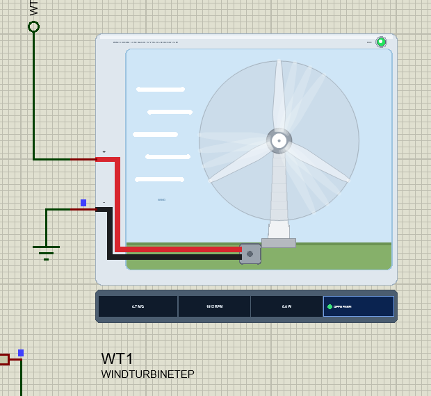
Search wind in Pick Devices; the device WINDTURBINETEP is in TEPWIND.LIB (category Electromechanical, Motors) and its model is TEPWIND.DLL. It is drawn from upwind, the way you look at a turbine facing the wind: a sky with a strip of grass, the tapered white tower on its concrete pad, the grey nacelle behind the white spinner, three white blades, wind streaks on the left, and the red + and black - cables running from the pins along the ground to the junction box at the tower's foot.
At Run the blades turn. Slowly, you see each blade move; above 60 RPM they blur into a faint disc with smeared blades, as your eye sees a real rotor. The OUT LED lights green while the generator gives more than 1 V, and the strip under the plate shows the wind, the rotor's speed, the power into the load and the OPEN PANEL button. The plate, the LED, the rating line and the strip are TEP additions; the real turbine has none of them.
The Pins and the Properties
| Pin | What the model does with it |
|---|---|
| + | the generator's positive output: its EMF behind 1.5 ohm and 3 mH |
| - | the generator's negative output |
| Property | Default | What it does |
|---|---|---|
| WIND | 6 | the wind in m/s (0 - 25), or DEMO for the 90 s demo profile |
| GUSTS | 10 | the gusts, in % of the wind (0 - 50; 0 = steady) |
The DEMO profile runs for 90 s and then starts again: calm for 4 s, 3 m/s until 14 s, 7 m/s until 30 s, 10 m/s until 46 s, 13 m/s until 58 s, 7 m/s until 72 s, 3 m/s until 82 s and calm again. A new wind does not arrive in a step: the mean wind moves to it over about 1.5 s, and the gusts ride on top as three slow waves.
Download Wind Turbine Generator Library for Proteus
Click the button below to download Wind-Turbine-Generator-Library-for-Proteus-v1.0.zip (about 1.2 MB, without the source code of the models):
Wind Turbine Generator Library for Proteus V1.0- README.txt: installation, the demo, the wiring, the properties, real hardware, troubleshooting and the limits.
- Proteus Library Files:
TEPWIND.LIBandArduinoV4TEP.LIBfrom our Arduino Library for Proteus V4.0. - Proteus Model Files:
TEPWIND.DLLandTEPARDUINO.DLL. - Proteus Simulation:
Wind-Turbine-Relay-ArduinoUnoV4.pdsprj,Wind_Demo.hexand copies of the two DLLs. - Arduino Code:
Wind_Demo.ino(no library needed).
Good to know: the demo's relay is our Relay Module, a separate library that is not in this zip. Download it from its own article, the Relay Module Library for Proteus, and install TEPRELAY.LIB and TEPRELAY.DLL the same way.
No Proteus yet? Read How to Download and Install Proteus 7 and 8. New to libraries? Follow How to Install a New Library in Proteus.
How to Install Wind Turbine Generator Library for Proteus
- Close Proteus and extract the whole zip file, for example to your Desktop.
- Copy
TEPWIND.LIBandArduinoV4TEP.LIBfrom Proteus Library Files into the LIBRARY folder of Proteus (usuallyC:\Program Files (x86)\Labcenter Electronics\Proteus 8 Professional\LIBRARY). - Copy
TEPWIND.DLLandTEPARDUINO.DLLfrom Proteus Model Files into the MODELS folder. The two Arduino files are the ones of our Arduino Library V4.0; if you have it, they are the same. - Install the Relay Module library the same way if you do not have it yet.
- Delete
TEPWIND.IDXfrom the LIBRARY folder if it is there. - Start Proteus, press P and search for wind.
Tip: keep the Proteus Simulation folder together, because the project needs its .hex file and the DLLs beside it. The library is tested in Proteus 8.5; Proteus 7 is not supported.
The Demo Circuit
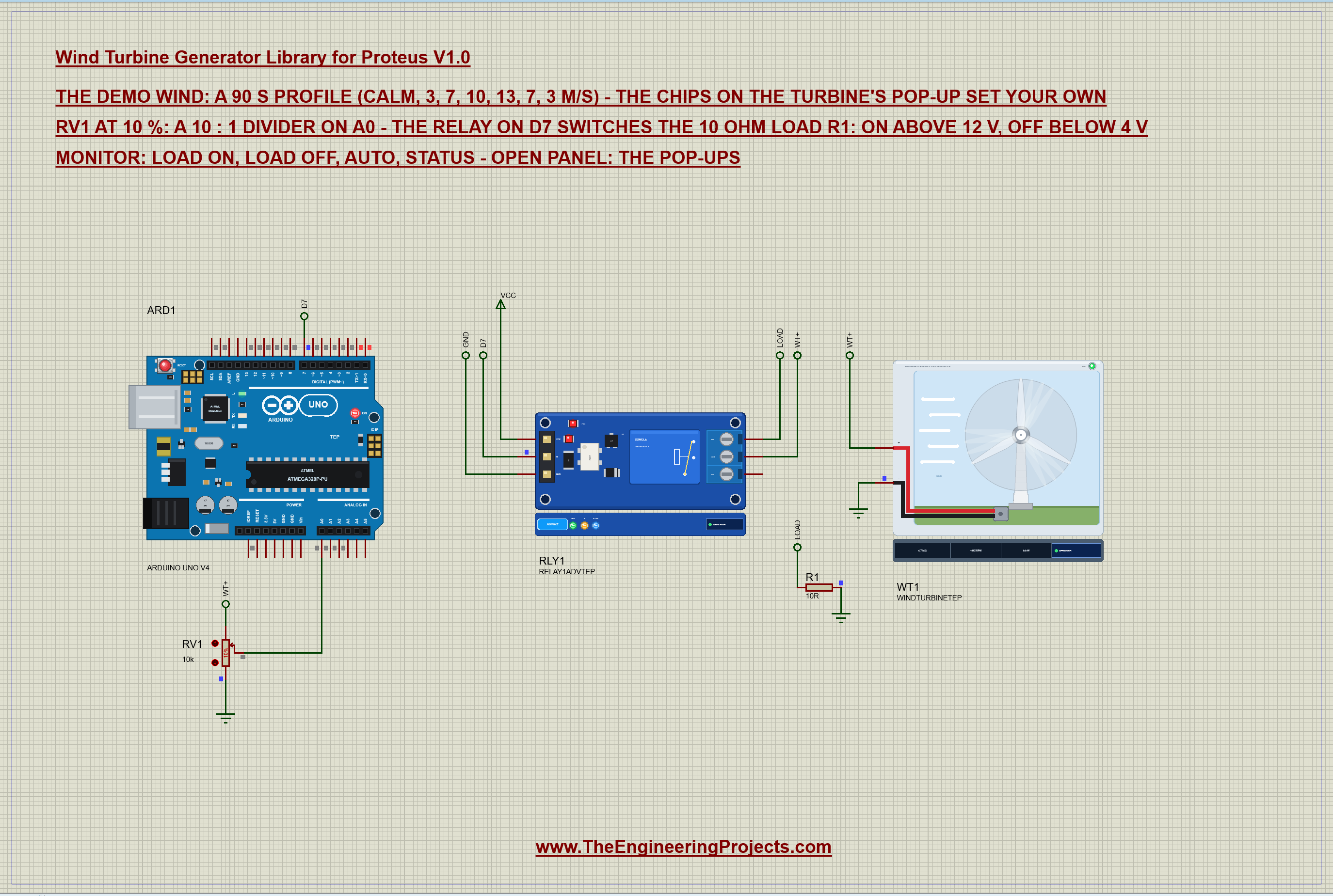
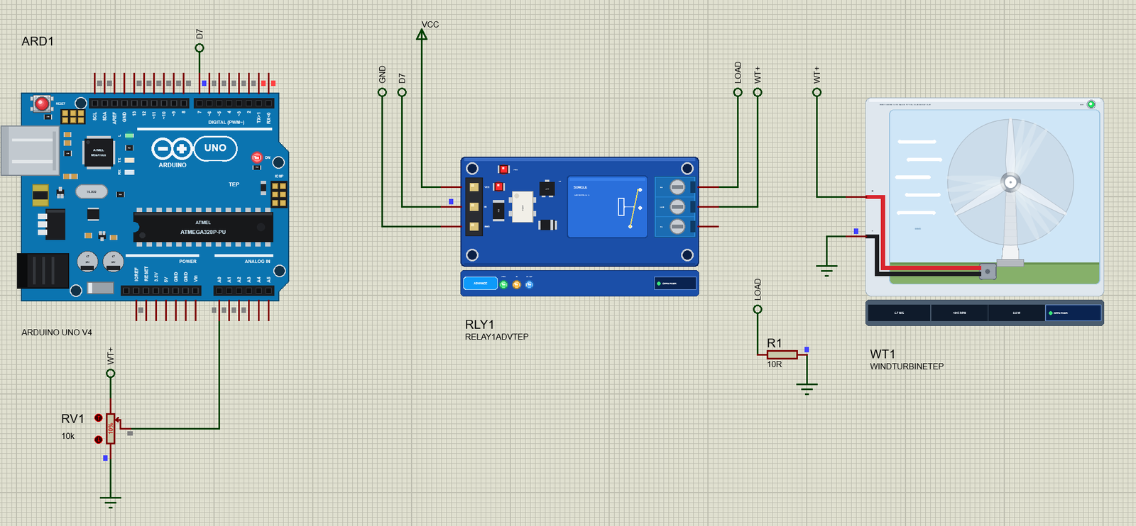
Open Wind-Turbine-Relay-ArduinoUnoV4.pdsprj. ARD1 is an Arduino UNO V4.0 from our Arduino UNO Library for Proteus V4.0, running Wind_Demo.hex with its serial monitor built in. RLY1 is our 1-channel relay module in its pop-up version. WT1 is the turbine with WIND set to DEMO, R1 is the 10 ohm load and RV1 is a 10k pot at 10 %: a 10 : 1 divider from the turbine's + into A0. The nets are joined by labels.
| Part | Pin | Goes to |
|---|---|---|
| Relay module | IN | D7 (active LOW: LOW = the relay on) |
| Relay module | VCC, GND | 5 V, ground |
| Relay module | COM, NO | WT+ (the turbine's +), LOAD (R1) |
| Turbine | +, - | WT+, ground |
| R1 (10 ohm) | 1, 2 | LOAD, ground |
| RV1 (10k, 10 %) | top, wiper, bottom | WT+, A0, ground |
Why a Relay and a Divider?
The relay's contact sits between the turbine and its load, so the UNO decides whether the turbine works into 10 ohm or into nothing at all. The relay module takes care of the coil current, the flyback diode and the optocoupler; the UNO only pulls IN low. The pot set to 10 % passes a tenth of the turbine's voltage to A0, so 50 V would still read as 5 V. In a real build, use two fixed resistors (for example 90k and 10k) - a pot can be turned by accident.
The Arduino Code
The sketch needs no library. New to Arduino? Start with Arduino Tutorial for Beginners and Introduction to Arduino UNO. The pins and the numbers come first:
const byte RELAY = 7;                         // the relay module's IN: LOW = the load on
const byte SENSE = A0;                        // RV1's wiper: the turbine's + through a 10 : 1 divider
const float DIVIDER = 10.0;                   // RV1 at 10 %
const float R_LOAD = 10.0;                    // RL1, ohm
const float ON_V = 12.0, OFF_V = 4.0;         // the automatic switching
One more number turns the voltage into the rotor's speed when there is no load: the generator gives 10.5 V per 1000 RPM.
const float RPM_PER_V = 95.5; // open circuit: 10.5 V per 1000 RPMSwitching the load is one line. The relay module is active LOW, so LOW on its IN pin closes the contact:
void load(bool on) { digitalWrite(RELAY, on ? LOW : HIGH); loadOn = on; }For the same reason the sketch writes the pin HIGH before it makes it an output. That way the relay never clicks on for a moment at power-up:
  digitalWrite(RELAY, HIGH);                  // the relay OFF before the pin drives (no click at power-up)
  pinMode(RELAY, OUTPUT);
The voltage is read sixteen times and averaged, which smooths the ripple of the gusts, then scaled back up by the divider:
float volts() {                               // 16 readings averaged
  long sum = 0;
  for (byte k = 0; k < 16; k++) sum += analogRead(SENSE);
  return sum / 16.0 * 5.0 / 1023.0 * DIVIDER;
}
Every 200 ms the automatic mode decides about the load. It connects the load only above 12 V, when the rotor is spinning fast enough to carry it, and drops it below 4 V, so a light wind can spin the rotor up again before the load brakes it. The wide gap between the two thresholds stops the relay from chattering:
    if (!loadOn && v > ON_V) { load(true); Serial.print(F("Load ON - ")); Serial.print(v, 1); Serial.println(F(" V")); }
    else if (loadOn && v < OFF_V) { load(false); Serial.print(F("Load OFF - ")); Serial.print(v, 1); Serial.println(F(" V: too little wind")); }
Every 3 s the sketch prints a reading. With the load on, Ohm's law gives the current and the power from the voltage alone; with no load, the voltage is the generator's EMF, which gives the rotor's speed - 95.5 RPM per volt for this turbine:
  if (loadOn) {
    Serial.print(F("load ON  ")); Serial.print(v / R_LOAD, 2); Serial.print(F(" A  "));
    Serial.print(v * v / R_LOAD, 1); Serial.println(F(" W"));
  } else {
    Serial.print(F("load off  (about ")); Serial.print(v * RPM_PER_V, 0); Serial.println(F(" RPM)"));
  }
Two commands take the load out of the automatic mode, so you can try what happens without it:
  if (!strcmp(s, "load on")) { autoMode = false; load(true); Serial.println(F("Load ON - held until auto")); return; }
  if (!strcmp(s, "load off")) { autoMode = false; load(false); Serial.println(F("Load OFF - held until auto: no load, the rotor speeds up")); return; }
The HEX file is in the package. To change the sketch, open it in the Arduino IDE and export the compiled binary, as in How to get the HEX file from Arduino. It needs 6,024 bytes of flash (18 % of the UNO) and 281 bytes of RAM.
Running the Demo
Press Run. The UNO's serial monitor, the turbine's pop-up and the relay module's pop-up open over the schematic; move them aside. The monitor starts with:
Wind Turbine demo - The Engineering Projects
RV1 on A0: a 10 : 1 divider. The relay on D7 switches the 10 ohm load: ON above 12 V, OFF below 4 V.
Commands: load on | load off | auto | status | help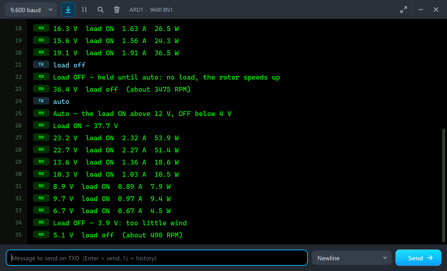
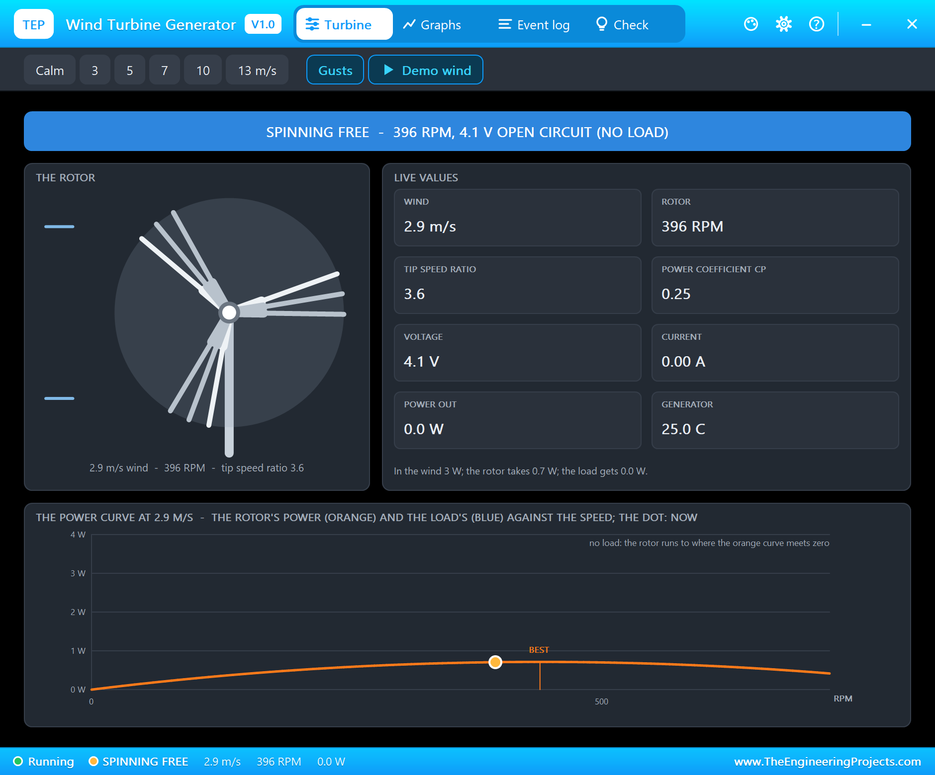
The demo wind starts calm. At 4 s it rises to 3 m/s, and a few seconds later the log says "SPINNING - the rotor cut in at 2.5 m/s": the gusts have just pushed the wind over the cut-in. With no load, the rotor speeds up slowly - a light wind has little torque to give - and settles towards its free speed: "FREE - 3.4 V open circuit at 321 RPM (2.8 m/s, tip speed ratio 3.0): no load". The sketch leaves the load off, because 4 V is far under its 12 V threshold.
The Load Comes On
At 14 s the demo wind rises to 7 m/s. The free rotor speeds up, its voltage passes 12 V and the sketch switches the relay on. The log shows the moment: "LOAD ON - 1.04 A at 10.5 V: 10.9 W" - the voltage drops as soon as the current flows, and the rotor slows down under its new load. Four seconds later it has settled: "OUTPUT - 7.5 W at 8.7 V and 0.87 A (7.1 m/s, 955 RPM, tip speed ratio 3.5, Cp 0.25)".
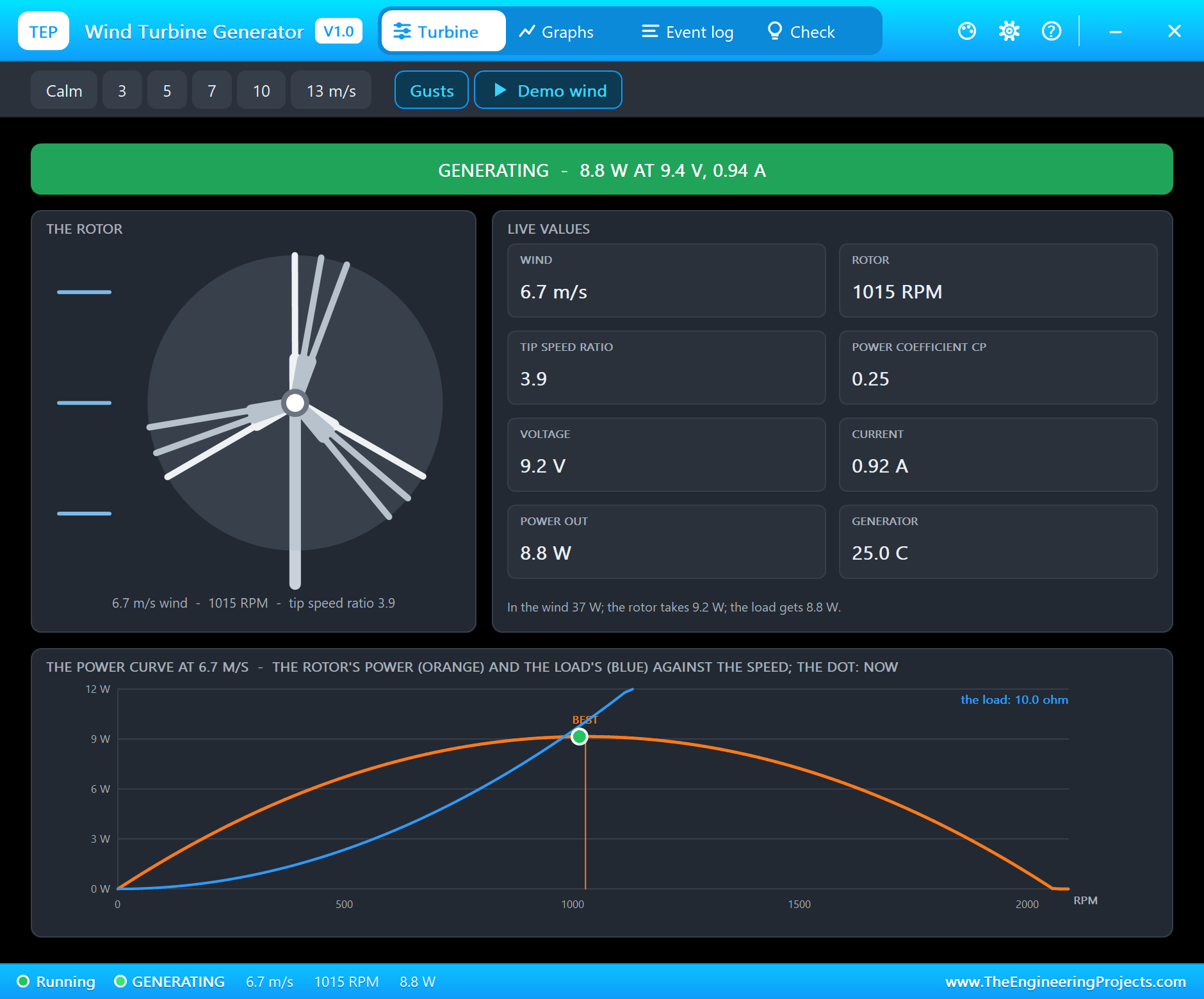
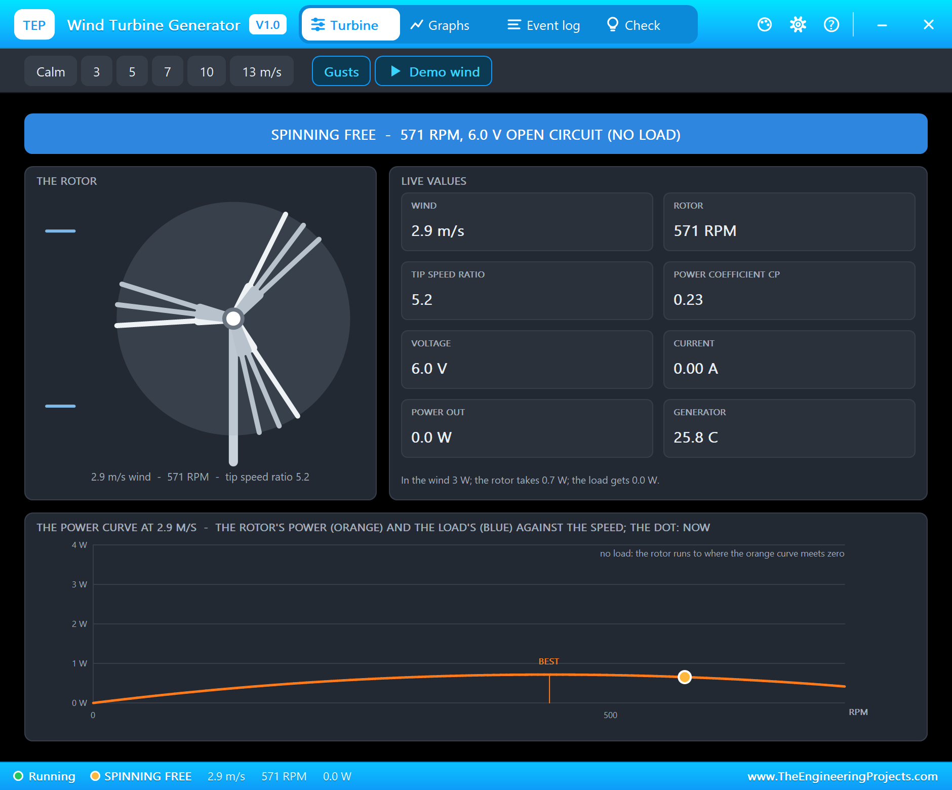
The pop-up has the look of our TEP Serial Monitor Advance for Proteus and four tabs: Turbine, Graphs, Event log and Check. The Turbine page has the wind chips on top - Calm, 3, 5, 7, 10 and 13 m/s, Gusts and Demo wind - then the state in big letters, here "GENERATING - 8.8 W AT 9.4 V, 0.94 A". Below are the rotor and eight live values: the wind, the rotor's speed, the tip speed ratio, Cp, the voltage, the current, the power out and the generator's temperature. A line under them puts the numbers side by side: "In the wind 37 W; the rotor takes 9.2 W; the load gets 8.8 W".
The bottom of the page is the power curve at the present wind. The orange curve is the power the rotor can take at each speed: zero at standstill, a peak at the best tip speed ratio (marked BEST), and zero again where a free rotor settles. The blue curve is what the load asks for at each speed - with 10 ohm it grows with the square of the speed. The turbine settles where the two curves meet, and the dot shows where it is now. At 7 m/s, our 10 ohm load meets the orange curve almost at its peak: a good match.
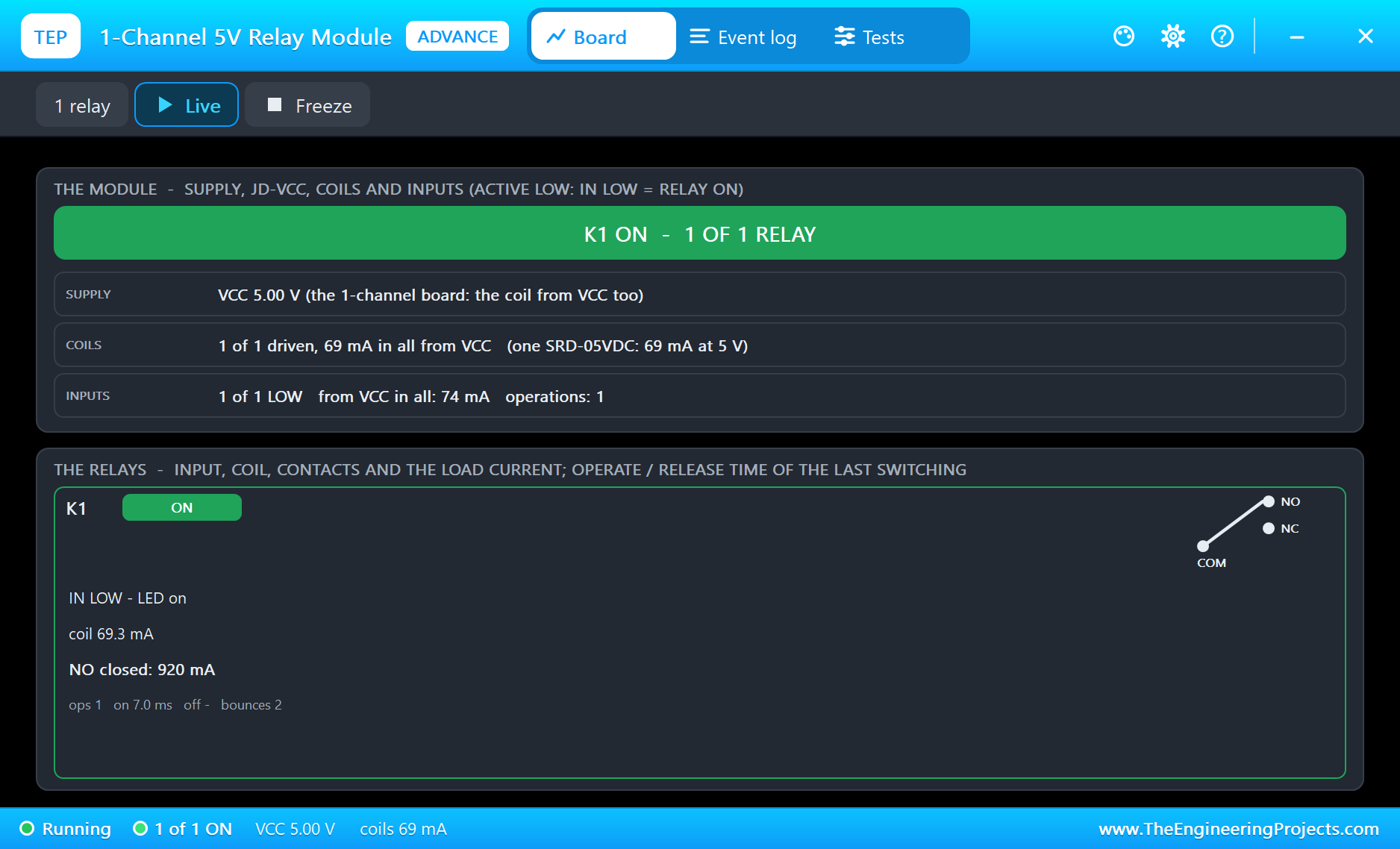
The relay module's pop-up shows the other side of the switch: K1 is on, its coil takes 69 mA, and its NO contact carries 920 mA from the turbine to the load. It also measured the relay's operate time, 7.0 ms, and counted two contact bounces.
The Rated Wind
At 30 s the wind rises to 10 m/s, the wind this turbine is rated for. The rotor speeds up, the voltage rises, and the power climbs with it: "OUTPUT - 17.8 W at 13.3 V and 1.33 A (9.5 m/s, 1465 RPM, tip speed ratio 4.0, Cp 0.25)", and 21.3 W a little later.
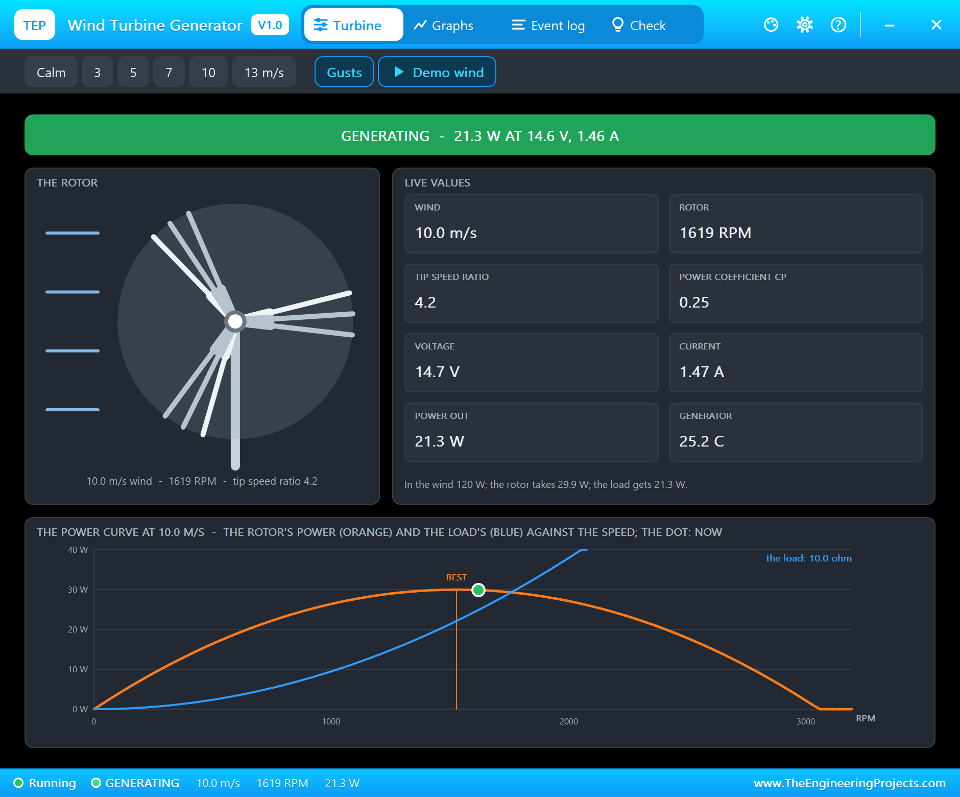
Look at the power curve again. At 10 m/s the peak is higher and further right, and the blue curve of the 10 ohm load now crosses the orange one a little past the peak. That is the catch with a fixed resistor: it is the best load at one wind speed only. Battery chargers for wind turbines with MPPT (maximum power point tracking) change the load as the wind changes, to keep the rotor at its best tip speed ratio.
A Strong Wind Without a Load: Overspeed
At 46 s the wind rises to 13 m/s. With the load connected, the rotor stays below 2700 RPM and the turbine gives about 50 W. Now try the classic mistake: type load off.
load off
Load OFF - held until auto: no load, the rotor speeds up
36.4 V  load off  (about 3475 RPM)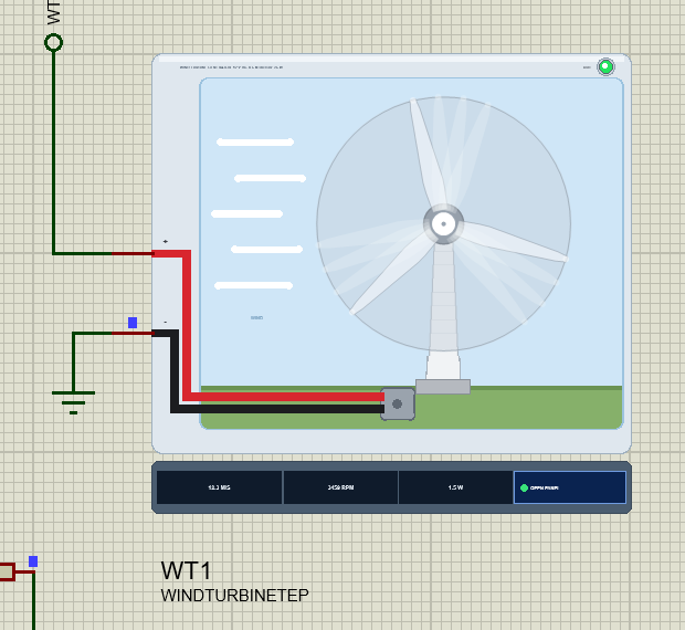
Without the load nothing holds the rotor back. Within a second it passes 3000 RPM and the warning comes: "OVERSPEED - 3211 RPM with no load in 13.1 m/s: keep a turbine loaded (or braked) in a strong wind". A second later it is at 3459 RPM (3599 RPM at its highest), and the open-circuit voltage reaches 36 V - the sketch reads 36.4 V and works out about 3475 RPM. On a real turbine this is how blades crack and bearings fail.
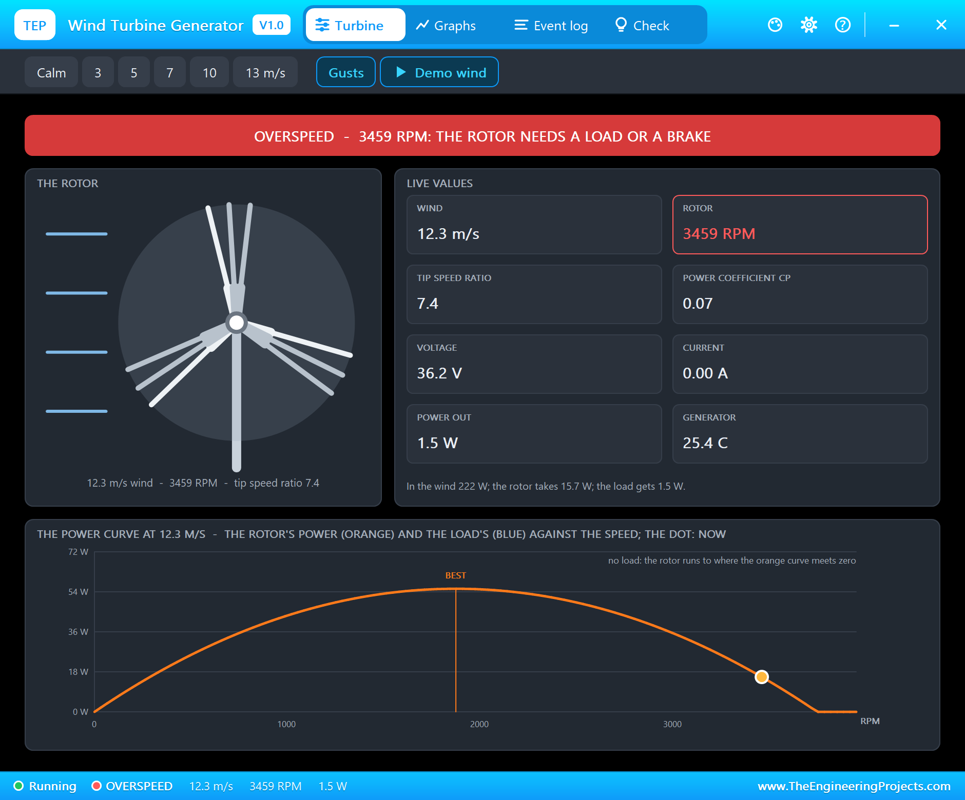
The pop-up turns red: "OVERSPEED - 3459 RPM: THE ROTOR NEEDS A LOAD OR A BRAKE". The power curve shows why the rotor stopped where it did: the dot has slid far down the right side of the orange curve, to a tip speed ratio of 7.4, where the blades take only enough power to cover the friction.
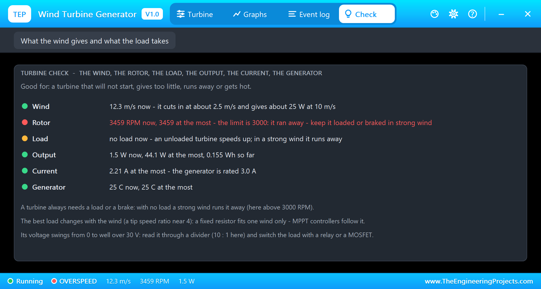
The Check page goes through the wind, the rotor, the load, the output, the current and the generator, each with a coloured dot. Here the Rotor row is red - the rotor ran past the 3000 RPM limit - and the Load row says there is no load and that an unloaded turbine runs away in a strong wind. Now type auto:
auto
Auto - the load ON above 12 V, OFF below 4 V
Load ON - 37.7 V
23.2 V  load ON  2.32 A  53.9 W
22.7 V  load ON  2.27 A  51.4 W
13.6 V  load ON  1.36 A  18.6 W
The sketch sees 37.7 V, far above 12 V, and switches the load straight back on. That is a hard moment for a turbine: the runaway rotor meets a 10 ohm load at full speed, and the log records the kick - "LOAD ON - 3.20 A at 32.1 V: 102.9 W". The current brakes the rotor, and within seconds it is back at a working point: "OUTPUT - 59.2 W at 24.4 V and 2.43 A (13.6 m/s, 2677 RPM, tip speed ratio 5.2, Cp 0.23)". Real controllers avoid that kick by never letting the rotor run away in the first place.
Light Wind Again
At 58 s the wind drops back to 7 m/s ("OUTPUT - 15.8 W at 12.6 V and 1.25 A"), and at 72 s to 3 m/s. With the load still connected, the rotor slows down, and with it the voltage, until the sketch's second threshold is reached:
6.7 V  load ON  0.67 A  4.5 W
Load OFF - 3.9 V: too little wind
5.1 V  load off  (about 490 RPM)
Below 4 V the sketch drops the load: in light wind, a 10 ohm load would hold the rotor so slow that it stalls. Freed, the rotor speeds up again, and the turbine waits for a wind strong enough to carry the load. If you hold the load on with load on in light wind, the model warns about the opposite mistake: in our tests, 10 ohm at 3.3 m/s held the rotor at 261 RPM and 2.4 V, far below its best tip speed ratio, and the Event log said STALLED.
Graphs and the Log
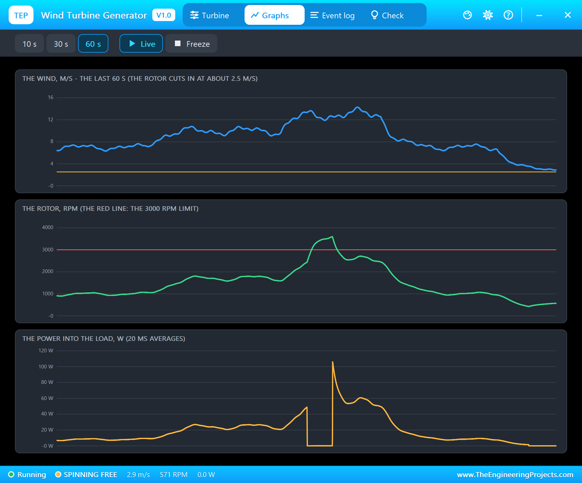
Graphs draws the wind, the rotor's speed and the power into the load over the last 10, 30 or 60 seconds. The 60 s view tells the whole story of the demo: the gusty wind rising to 10 and 13 m/s and falling back; the rotor following it, then jumping over the red 3000 RPM line when the load was switched off; and the power, which drops to zero while the load is off and comes back with the kick of more than 100 W when it is switched on again.
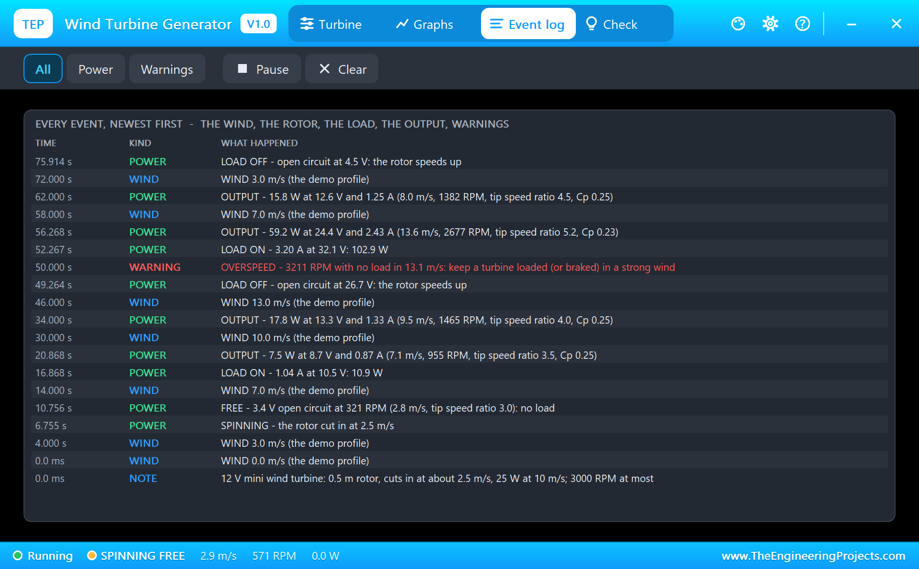
The Event log keeps every wind change, every start and stop of the rotor, every switching of the load, the settled output four seconds after each change, and every warning with its reason. Filter it to Power or Warnings, pause it, or clear it.
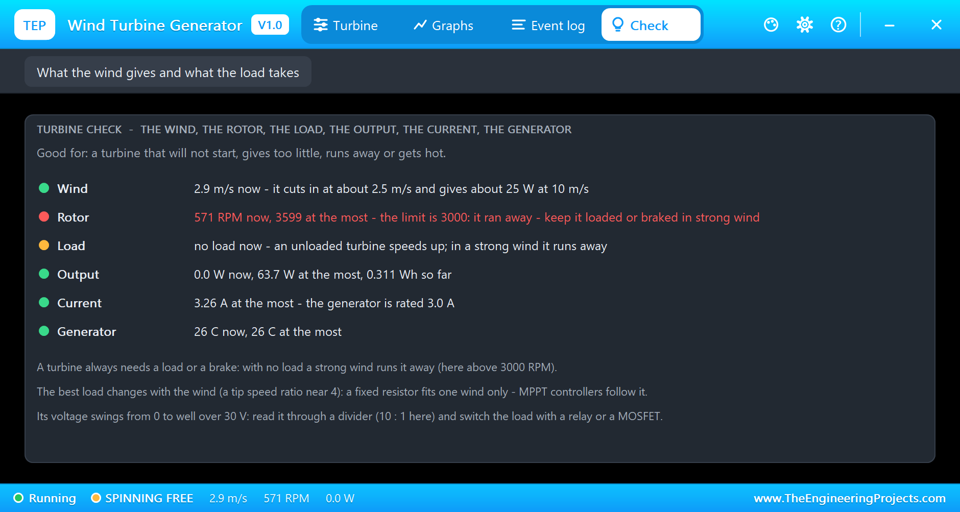
The Check page at the end of the run remembers the overspeed - 3599 RPM at the most - and adds up the run: 63.7 W at the most and 0.311 Wh in total, with the generator at a cool 26 C. Its tips sum up this article: a turbine always needs a load or a brake, the best load changes with the wind, and its voltage needs a divider before it reaches a pin.
How the Model Works
The generator sits between + and - as its EMF - 0.10 V for every rad/s of the rotor - behind the winding's resistance (1.5 ohm at 25 C, rising as the copper warms) and its 3 mH inductance. At every analog step the model puts a conductance and a current source into the circuit that stand for that winding, so whatever is connected - a resistor, a relay, a battery through a diode - draws the right current. That current, times the same 0.10, is the torque that brakes the rotor.
The rotor follows the wind's torque, the generator's torque and the friction. The wind's torque comes from the power coefficient: Cp = 0.25 x (tip speed ratio / 4) x (2 - tip speed ratio / 4), which gives the rotor a starting torque at standstill and a braking torque beyond its runaway speed. The cogging and the bearings need 24 mN.m to break the rotor away from rest - that is the 2.5 m/s cut-in - and 6 mN.m while it turns. The rotor and the generator's heat run in steps of at most 1 ms between the analog points, which are held to 1 ms while the rotor turns (5 ms at rest).
We checked the model on a PC with 10 automatic tests: it cuts in between 2.3 and 2.8 m/s; free at 7 m/s it runs at about 2000 RPM and 21 V; into 10 ohm it gives 2.7 W at 5 m/s, 8.2 W at 7 m/s, 24.3 W at 10 m/s and 51 W at 13 m/s within its limits; free at 13 m/s it runs away to 3882 RPM with the OVERSPEED warning; at 3.3 m/s the 10 ohm load stalls it; and a short circuit at 10 m/s brakes it from 1711 to 463 RPM in 3 s. The demo project is read back from disk with 69 checks.
Troubleshooting
- The rotor stands still (BECALMED): the wind is under about 2.5 m/s - click a stronger wind chip, or set WIND above 3.
- It spins but gives nothing (SPINNING FREE): no load on + and -, or the relay is off.
- OVERSPEED: no load, or too light a load, in a strong wind - connect the load.
- STALLED: the load is too heavy for this wind - use a bigger resistor, or let the sketch drop the load below 4 V.
- The turbine is not simulated:
TEPWIND.DLLis missing from MODELS and from the project folder. - No relay: install our Relay Module library (
TEPRELAY.LIBandTEPRELAY.DLL). - No UNO or no monitor:
TEPARDUINO.DLLis missing; a closed monitor opens again with a click on the UNO's USB port. - No pop-up: click OPEN PANEL on the strip, or turn "Open the panel at Run" back on in its Settings.
Things to Know Before Building a Real One
- Divide the voltage: an unloaded turbine gives well over 30 V in a strong wind. Read it through a divider, with a Zener or a clamp on the analog pin.
- Never leave it unloaded: keep a dump load connected when the battery is full, or brake the generator by shorting it through a resistor.
- Match the load: a fixed resistor suits one wind speed; an MPPT charge controller follows the best point as the wind changes.
- Charging a battery: put a blocking Schottky diode in the line, so the battery does not drive the generator as a motor when the wind drops, and a fuse.
- Switch it with care: a relay or a MOSFET rated for the current and the voltage - and expect a current kick if a load meets a fast rotor.
Limitations of the Simulation
- Not modelled: the tail turning the rotor into the wind, furling, blade pitch, the tower's shadow, the sound, and the 3-phase alternators and rectifiers of bigger turbines.
- The plate, the OUT LED, the rating line and the strip are TEP additions.
- The model is our own, written from the typical data of small DC wind turbines; this library is not made or endorsed by any wind turbine maker, Arduino or Labcenter.
- Licences: the demo HEX contains the Arduino AVR core 1.8.6 (LGPL); the sketch is included and the README gives the source link. The relay module of the demo is our separate library.
- Tested in Proteus 8.5 in October 2026 with the demo as shipped: the demo wind from calm to 13 m/s and back, the automatic switching, the overspeed, the reconnection and all four pages of the pop-up. Proteus 7 is not supported.
So, that was all about the Wind Turbine Generator Library for Proteus V1.0. I hope it helps you with your wind power logger, your charge controller or your science fair turbine - and saves a real rotor from running away. If you have any questions, ask in the comments and I will help you out. Till the next tutorial, take care and have fun!

Comments
0