


TTP229 Touch Keypad Library for Proteus V1.0: 16-Key Capacitive Keypad


Hello friends, I hope you all are doing great. Today, I am going to share the new TTP229 Touch Keypad Library for Proteus V1.0. The red TTP229 16-key capacitive touch keypad is the easiest way to give an Arduino project a modern, button-free front panel: sixteen round pads under a thin cover, no moving parts, nothing to wear out. It talks to the Arduino over two wires, SCL and SDO, and for a hobby board it hides a surprising number of traps: it comes with only 8 of its 16 keys switched on, it reports one key at a time unless you bridge two pads, and its serial interface is not I2C at all.
Behind the parts sits our own model, written from the TTP229-BSF datasheet. You click the pads on the board while the simulation runs, and the chip answers the way the real one does: it calibrates at power-on, sleeps and wakes up, scans its keys every 16 or 32 ms, shifts the keys out bit by bit on SDO, pulses SDO when a key is ready, and resets its interface after 2 ms without a clock. The eight option pads TP0 - TP7 are clickable too. You get a Simple device with a live STATUS panel and an Advance device with a pop-up window that draws SCL and SDO through the last read, bit by bit. The demo runs on our Arduino UNO V4.0.
NOTICE: a touch keypad is easy to fake: a part that hands the key you click straight to the sketch. We wanted more. Our TTP229 talks only the way the real chip talks - a bit on SDO for each clock on SCL - so a sketch that reads too few bits, clocks too fast, reads too often, gets the polarity wrong or forgets the 16-key jumper fails exactly as it does on a real board, and the model tells you why. It took our team a lot of hard work. Your feedback is the fuel that keeps us going, so please tell us what you think in the comments below or in the touch keypad board of our forum. And if our free libraries help you, you can buy us a coffee. So, let's get started with the TTP229 Touch Keypad Library for Proteus V1.0:
What is the TTP229 Touch Keypad?
The TTP229-BSF from Tontek is a capacitive touch pad detector: it measures the tiny capacitance of up to 16 copper pads and notices when a finger comes close. The module sold for Arduino puts the chip on a square board with 16 round pads, numbered 1 - 16, a header with VCC GND SCL SDO OUT1 - OUT8, and eight small option pads, TP0 - TP7, that you bridge with solder to change what the chip does.
| TTP229 16-key touch keypad module | |
|---|---|
| Chip | TTP229-BSF (TonTouch), SSOP-28 |
| Supply | 2.4 V - 5.5 V (5 V from the UNO) |
| Pads | 16 (8 as the board comes - bridge TP2 for 16) |
| Interface | 2-wire serial: SCL in, SDO out (not I2C); 8 direct outputs OUT1 - OUT8 in 8-key mode |
| Response | a scan every 32 ms with 16 keys, 16 ms with 8 |
| Power-on | 0.5 s of calibration - keep fingers off |
How the Arduino Reads the Keys
The two-wire interface is simple. As the board comes it is active-low: SCL rests HIGH, and each time the Arduino pulls SCL LOW the chip puts the next key's bit on SDO - key 1 first. SDO LOW means touched. Sixteen clock pulses read all sixteen keys. After the last clock the Arduino waits: when SCL has not changed for 2 ms, the interface resets and the next read starts again at key 1. While a key is reported, the chip also pulses SDO LOW for 93 us after each scan - the data-valid (DV) pulse - so a sketch can wait for it instead of reading all the time.
The Option Pads TP0 - TP7
The chip reads its option pads once, at power-on. A bridged pad is the datasheet's resistor to ground; an open pad keeps the default:
| Pad | Open (as the board comes) | Bridged |
|---|---|---|
| TP0 | OUT1 - OUT8 CMOS | open drain / open collector |
| TP1 | SDO active-low, OUT active-high | SDO active-high, OUT active-low |
| TP2 | 8 keys (TP0 - TP7) | 16 keys |
| TP3 + TP4 | single-key: the lowest pad touched | both bridged: multi-key; one: two groups |
| TP5 | wake-up 8 times a second | 64 times a second |
| TP6 | wake-up sampling 4 ms | 2 ms |
| TP7 | a pad may stay touched for ever | let go after about 80 s |
What's New in TTP229 Touch Keypad Library for Proteus V1.0
- Clickable pads: click a pad on the board while the simulation runs - it is touched while the mouse button is down, at least PRESS ms (150 by default).
- Clickable option pads: TP0 - TP7 on the board (or in the pop-up) bridge and open with a click; the chip starts again with the new options.
- The real 2-wire interface: a bit on SDO for each clock on SCL, active-low or active-high, the 2 ms reset, the 93 us DV pulse.
- The chip's timing: the 0.5 s calibration, sleep and the 8 Hz wake-up, a scan every 16 or 32 ms, single-key and multi-key, the maximum key-on time.
- The reader seen from the board: reads a second or after DV, clocks per read, the clock frequency, the level SCL rests at, reads closer than 2 ms, keys no read got.
- Four actions: SWEEP 1-16, HOLD 1 2 3, LATCH (a click puts a finger on a pad, the next lifts it) and ALL OFF.
- The last read in the Advance pop-up: SCL and SDO with the bits D0 - D15 named on the clock edges.
- Three test tools on the Advance device: Options & mode, Serial read, and Touch & timing.
- A two-node demo on our Arduino UNO V4.0 with no library: a 16-key board and a board as it comes, the same sketch, and the KEYS, READ, RATE, POL, RAW and STATUS commands.
- A compact package: about 1.26 MB, without the C++ source code of the model.
Two Devices: Simple and Advance
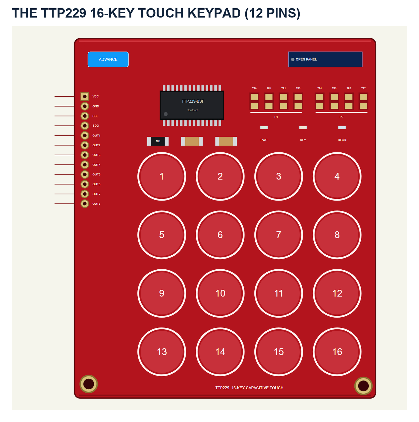
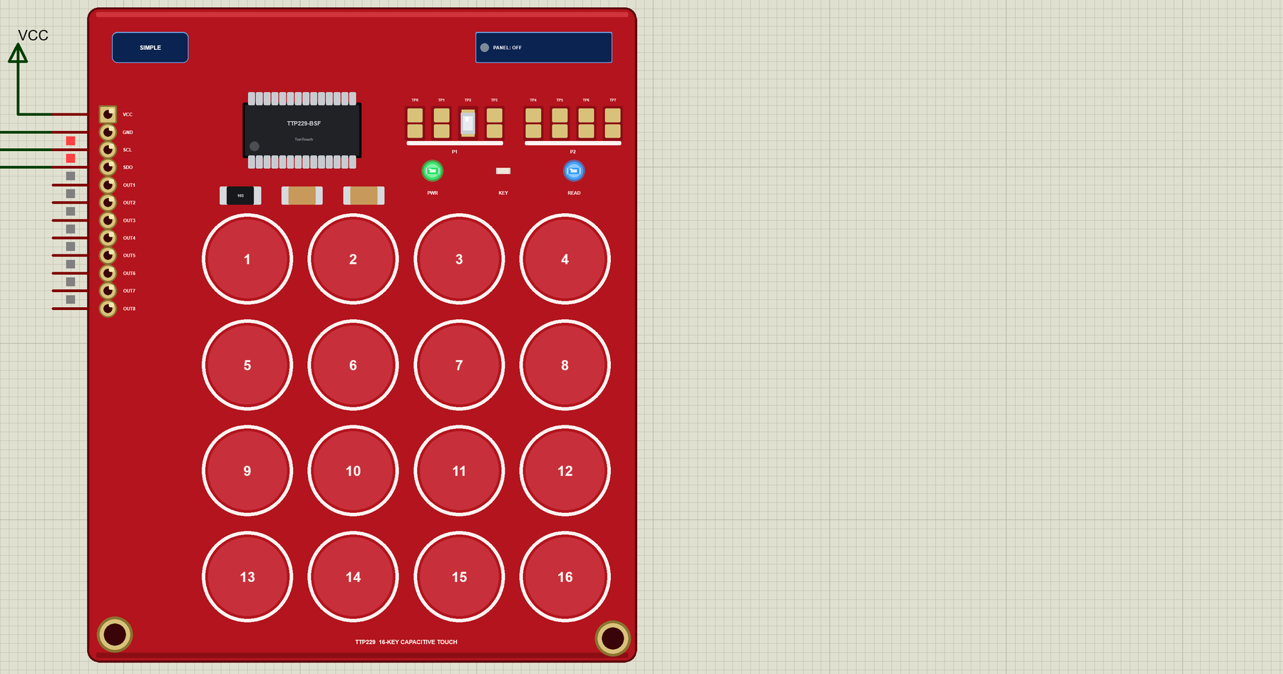
The part shows the red board with the white rings of its 16 pads, the TTP229-BSF chip and the eight option pads in two groups, P1 (TP0 - TP3) and P2 (TP4 - TP7). The pins point left: VCC GND SCL SDO OUT1 - OUT8. The SIMPLE / ADVANCE badge, the PWR, KEY and READ LEDs and the panel button are TEP additions: PWR lights with power, KEY while the chip reports a key, READ for a moment after each read.
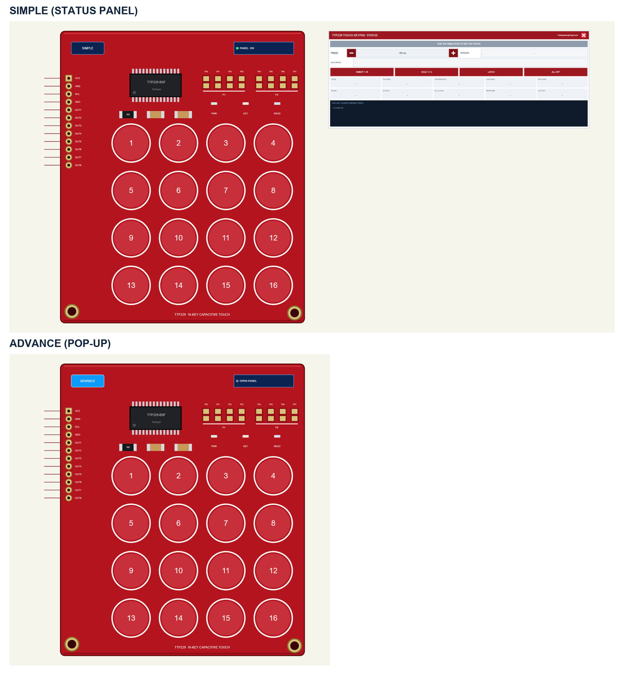
| Simple | Advance | |
|---|---|---|
| Device | TTP229TEP | TTP229ADVTEP |
| On the schematic | The board and the STATUS panel | The board |
| The pads | Clickable on the board | Clickable on the board and in the pop-up |
| The option pads | Clickable on the board | On the board and in the pop-up |
| Status | Banner, 10 readouts, the last 4 events | A pop-up: Keypad, Event log, Tests |
Download TTP229 Touch Keypad Library for Proteus
Click the button below to download TTP229-Touch-Keypad-Library-for-Proteus-v1.0.zip (about 1.26 MB, without the C++ source code of the model):
TTP229 Touch Keypad Library for Proteus V1.0- README.txt: the devices, installation, the demo, wiring, the test tools and real hardware.
- Proteus Library Files:
TEPTTP229.LIBandArduinoV4TEP.LIBfrom our Arduino Library for Proteus V4.0. - Proteus Model Files:
TEPTTP229.DLLandTEPARDUINO.DLL. - Proteus Simulation:
TTP229-Touch-Keypad-ArduinoUnoV4.pdsprj,TTP229_Touch_Keypad_Demo.hexand copies of the two DLLs. - Arduino Code:
TTP229_Touch_Keypad_Demo.ino- it needs no library.
No Proteus yet? Read How to Download and Install Proteus 7 and 8. New to libraries? Follow How to Install a New Library in Proteus.
How to Install TTP229 Touch Keypad Library for Proteus
- Close Proteus and extract the whole zip file, for example to your Desktop.
- Copy the two files from Proteus Library Files into the LIBRARY folder of Proteus (usually
C:\Program Files (x86)\Labcenter Electronics\Proteus 8 Professional\LIBRARY). - Copy
TEPTTP229.DLLandTEPARDUINO.DLLfrom Proteus Model Files into the MODELS folder. - Delete
TEPTTP229.IDXfrom the LIBRARY folder if it is there. - Start Proteus, press P and search for TTP229.
Tip: keep the Proteus Simulation folder together, because the project needs its .hex file and the DLLs beside it. The library is tested in Proteus 8.5; Proteus 7 is not supported.
The TTP229 Part in Proteus
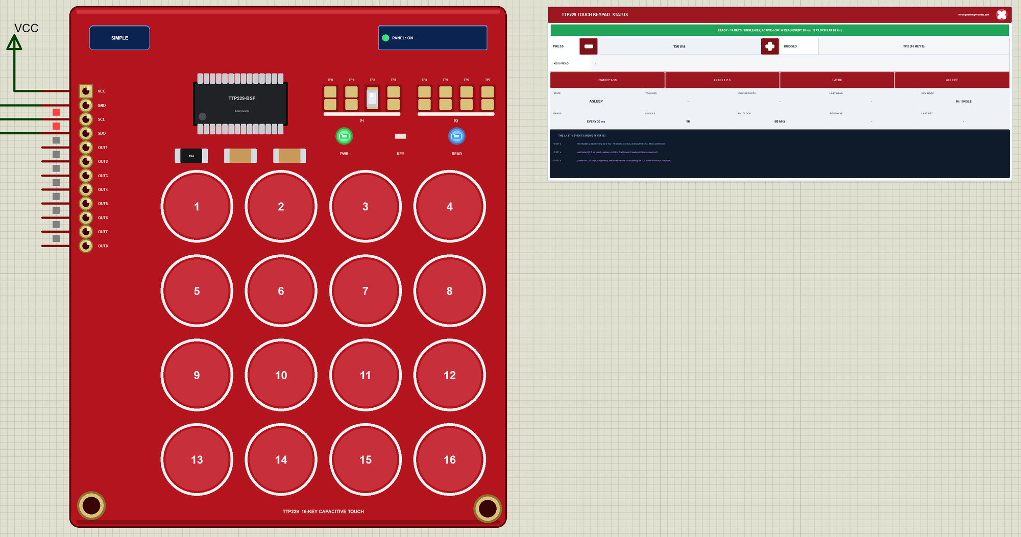
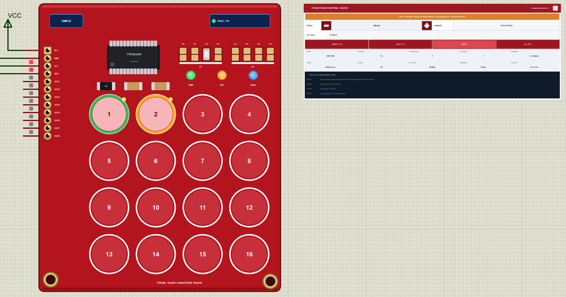
The Simple device adds the STATUS panel beside the board. Its banner says what the chip reports and what the sketch's reads get: green when all is well; amber for pads the chip ignores (8-key mode, single-key mode, a pad in the baseline) and for reads that clock too few bits; red for a clock that rests at the wrong level, reads closer than 2 ms, a clock faster than 512 kHz, or a key nothing reads; grey while the chip calibrates. Below it are - and + for PRESS (50 ms a click), the option pads bridged, the keys the reads got, four actions, ten readouts and the last four events.
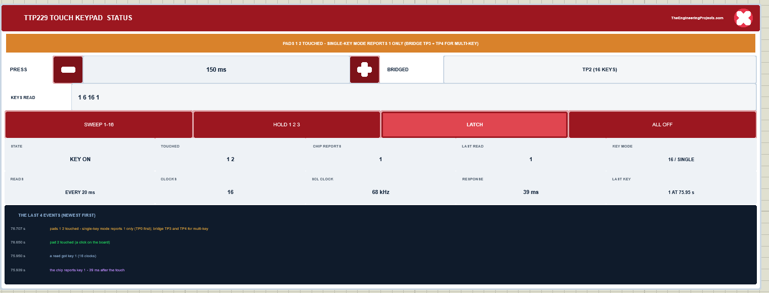
The readouts are the state, the pads touched, the keys the chip reports, what the last read got, the key mode, how often the sketch reads, the clocks per read, the clock frequency, the response time and the last key read. The actions: SWEEP 1-16 touches the pads one after the other, each for PRESS ms, 150 ms apart; HOLD 1 2 3 touches three pads at once, and a second click lets them go; LATCH changes what a click does - a click puts a finger on a pad and the next click lifts it, so you can hold several pads with the mouse; ALL OFF lifts every finger. The red X closes the STATUS panel, and the PANEL button opens it again:
The Advance device keeps the schematic clean: only the board. The live data opens in a pop-up window at Run, and the OPEN PANEL button on the board brings the window back. Its pads and option pads can be clicked on the schematic too:
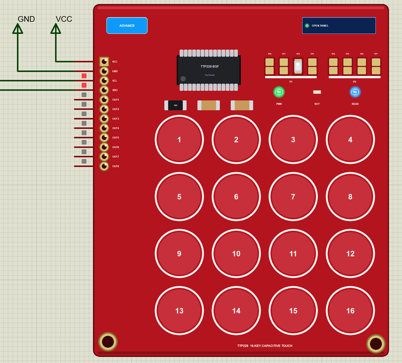
The properties set the start: OPTIONS, the option pads bridged (NONE as the board comes, or for example TP2, or TP2 TP3 TP4), and PRESS, the shortest touch of a click in ms (150). The Simple device also has PANEL (open or closed). Every run starts again from the properties.
The Demo Circuit
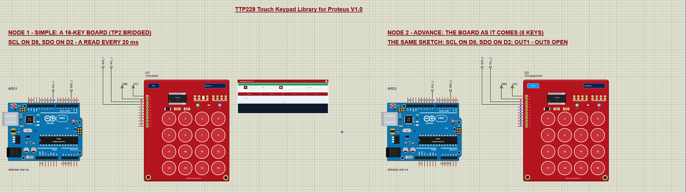
The demo project has two nodes, each an Arduino UNO V4.0 from our Arduino UNO Library for Proteus V4.0 with a TTP229 board. Node 1 has the Simple board with TP2 bridged - 16 keys. Node 2 has the Advance board as it comes, with no pad bridged - 8 keys, the trap most people fall into first. Both UNOs run the same TTP229_Touch_Keypad_Demo.hex.

Wiring
| Board pin | Arduino UNO (the demo) | Notes |
|---|---|---|
| VCC | 5V | 2.4 V - 5.5 V |
| GND | GND | |
| SCL | D8 | any digital pin, an OUTPUT |
| SDO | D2 | any digital pin, an INPUT; D2 / D3 for READ DV's interrupt |
| OUT1 - OUT8 | open | one output per key 1 - 8 in 8-key mode |
In the demo VCC and GND go to power terminals, and SCL and SDO run to labels (SCL_1, SDO_1 and SCL_2, SDO_2) at the UNO's header. The serial monitor needs no wires at all, because it is built into the UNO V4.0.
The Arduino Code
The demo sketch needs no library - sixteen clock pulses and a digitalRead() after each are all it takes. New to Arduino? Start with Arduino Tutorial for Beginners and Introduction to Arduino UNO. The pins:
const byte SCL_PIN = 8, SDO_PIN = 2; // SDO on D2: INT0 for READ DVIn setup() SCL is set HIGH before it becomes an output, so the chip never sees a stray clock edge:
  Serial.begin(9600);
  restClock();                                   // HIGH before the pin becomes an output: no stray clock edge
  pinMode(SCL_PIN, OUTPUT);
  pinMode(SDO_PIN, INPUT);
One Read
readKeys() makes one clock pulse per key. The falling edge brings the next bit out on SDO; the sketch reads it, notes LOW as touched, and lets SCL rest again. With POL HIGH the levels swap:
uint16_t readKeys(char *bitsOut) {
  uint16_t k = 0;
  for (byte i = 0; i < keys; i++) {
    digitalWrite(SCL_PIN, activeHigh ? HIGH : LOW);   // the active edge: the next bit comes out on SDO
    bool b = digitalRead(SDO_PIN);
    if (bitsOut) bitsOut[i] = b ? '1' : '0';
    if (b == activeHigh) k |= 1u << i;
    restClock();
  }
  if (bitsOut) bitsOut[keys] = 0;
  return k;
}
loop() reads every rateMs (20 ms at the start) - or, with READ DV, waits for the chip's data-valid pulse: an interrupt on D2 sets dvSeen, the sketch waits until the 93 us pulse is over, adds 20 us (the datasheet's Tw of at least 10 us) and only then clocks:
  if (dvMode) {
    if (dvSeen) {
      const unsigned long t0 = micros();
      while (digitalRead(SDO_PIN) == activeHigh && micros() - t0 < 200) {}   // until the 93 us DV pulse ends
      delayMicroseconds(20);                     // Tw: at least 10 us before the first clock
      readNow();
      dvSeen = false;                            // the read's own bits on SDO are not a DV
    }
  } else if (millis() - lastRead >= rateMs) {
    lastRead = millis();
    readNow();
  }
Touched and Released
report() compares each read with the last one and prints a line for every key that changed, with the time it was held:
void report(uint16_t now) {
  for (byte i = 0; i < 16; i++) {
    const uint16_t bit = 1u << i;
    if ((now & bit) == (held & bit)) continue;
    stamp();
    Serial.print(F("key "));
    Serial.print(i + 1);
    if (now & bit) {
      since[i] = millis();
      Serial.println(F(" touched"));
    } else {
      Serial.print(F(" released ("));
      Serial.print((millis() - since[i]) / 1000.0, 2);
      Serial.println(F(" s)"));
    }
  }
  held = now;
}
The Commands
KEYS 8 / 16 sets the clocks per read, READ POLL / DV how the sketch reads, RATE ms the time between two reads (1 - 500), POL LOW / HIGH the board's TP1, RAW 1 also prints the SDO bits of each new read, and STATUS sums it up. The interrupt for READ DV:
void setRead(bool dv) {
  detachInterrupt(digitalPinToInterrupt(SDO_PIN));
  dvMode = dv;
  dvSeen = false;
  if (dv) attachInterrupt(digitalPinToInterrupt(SDO_PIN), onDv, activeHigh ? RISING : FALLING);
}
The HEX file is in the package, so you do not need the Arduino IDE to run the demo. To change the sketch, open it in the Arduino IDE and export the compiled binary, as in How to get the HEX file from Arduino. It needs 7,766 bytes of flash and 398 bytes of RAM.
The Board as It Comes: Only 8 Keys
At Run, U2 opens its own window, TTP229 Touch Keypad, with the look of our TEP Serial Monitor Advance for Proteus. It has three tabs, Keypad, Event log and Tests, plus Settings and Help behind the gear and question mark icons. We clicked pad 5 in it:
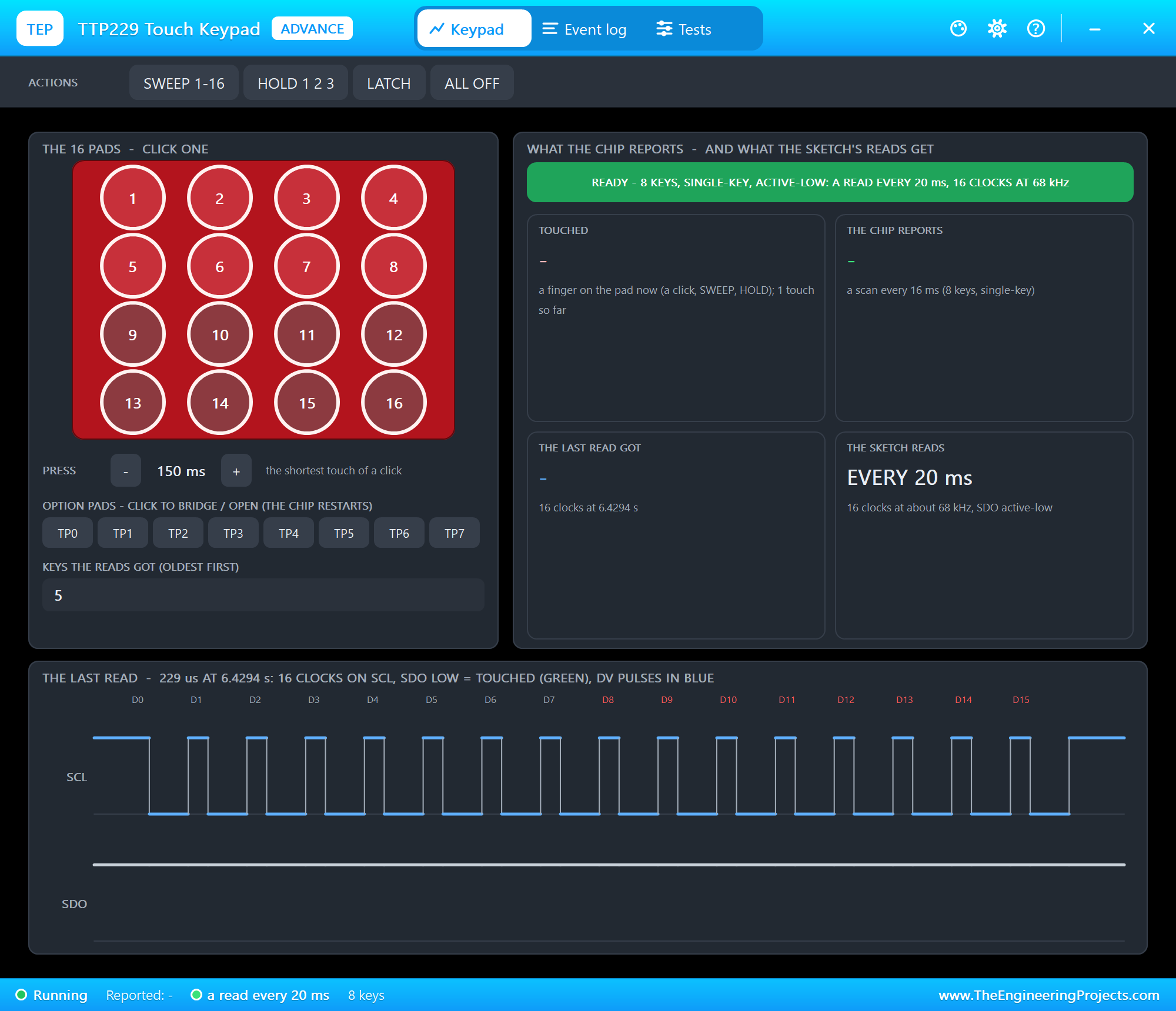
The Keypad page shows the 16 pads - click one -, PRESS, the option pads and the keys the reads got. What the chip reports has the banner and four tiles: the pads touched, the chip's report, what the last read got, and how the sketch reads. The last read draws SCL and SDO through the sketch's last read, with the bits named on the falling edges. Pads 9 - 16 are dimmed and D8 - D15 are red: this board is in 8-key mode. Then we latched pad 12:
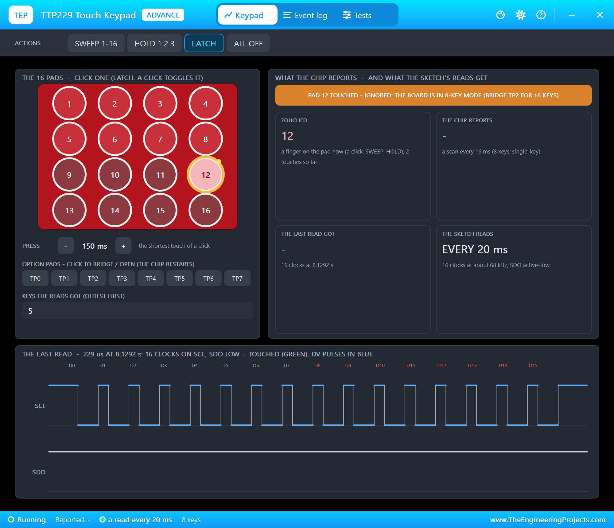
The chip simply does not look at pads 9 - 16 - the most common surprise with this board. The sketch printed key 5, and nothing for pad 12:
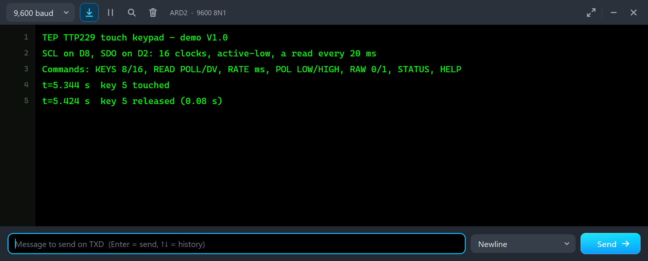
TEP TTP229 touch keypad - demo V1.0
SCL on D8, SDO on D2: 16 clocks, active-low, a read every 20 ms
Commands: KEYS 8/16, READ POLL/DV, RATE ms, POL LOW/HIGH, RAW 0/1, STATUS, HELP
t=5.344 s  key 5 touched
t=5.424 s  key 5 released (0.08 s)
The serial monitor is built into the UNO V4.0 and opens at Run; the screenshots use its Simple interface. Key 5 was reported only briefly: the chip was asleep, and a short click is half over before its 8 Hz wake-up sample finds it.
Options & Mode
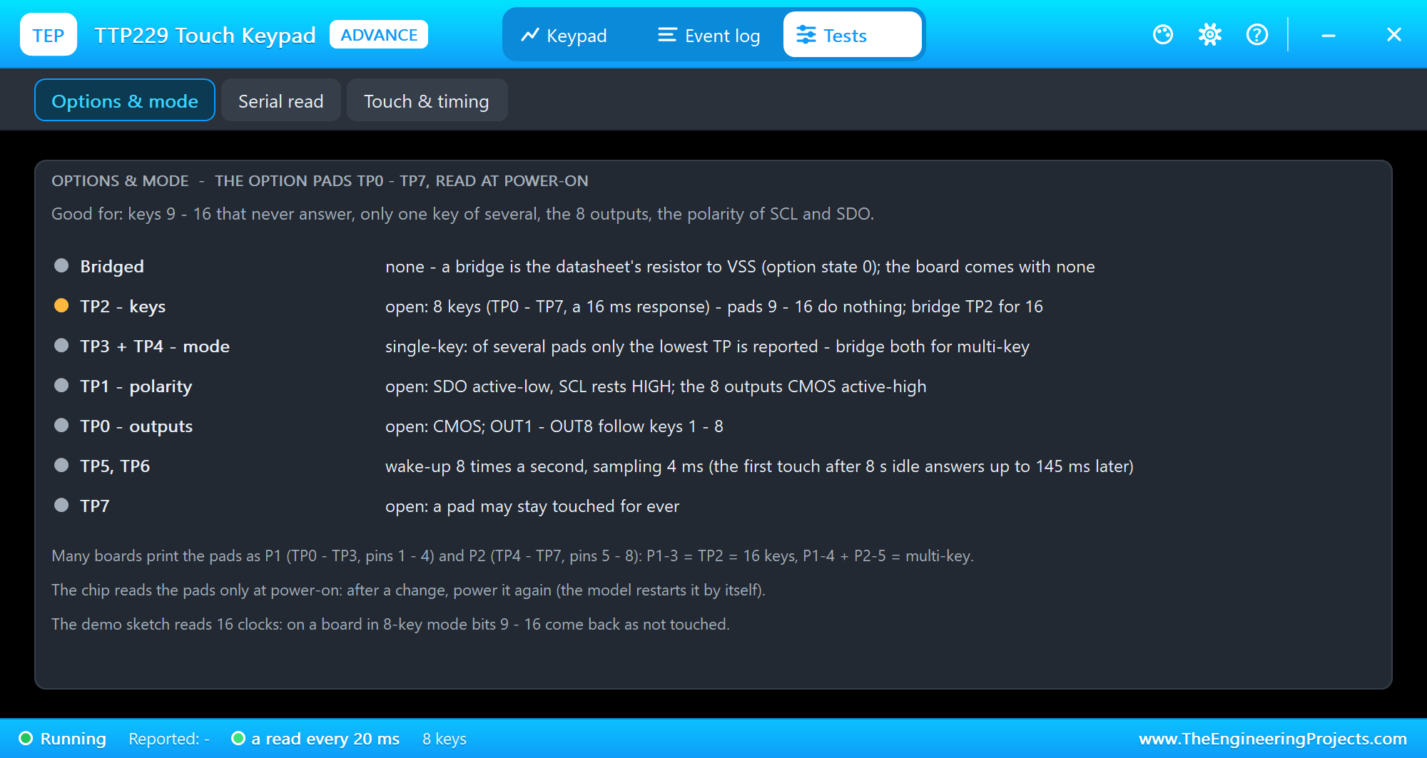
The Options & mode tool lists the pads bridged and what each of TP0 - TP7 does right now: the key count, single or multi-key, the polarity of SCL and SDO, the 8 outputs, the wake-up rate and the maximum key-on time. Open it first when keys 9 - 16 never answer or only one key of several comes.
TP2: All 16 Keys
We clicked TP2 in the pop-up. The chip reads its option pads only at power-on, so the model starts it again - 0.5 s of calibration - and then pad 12 works:
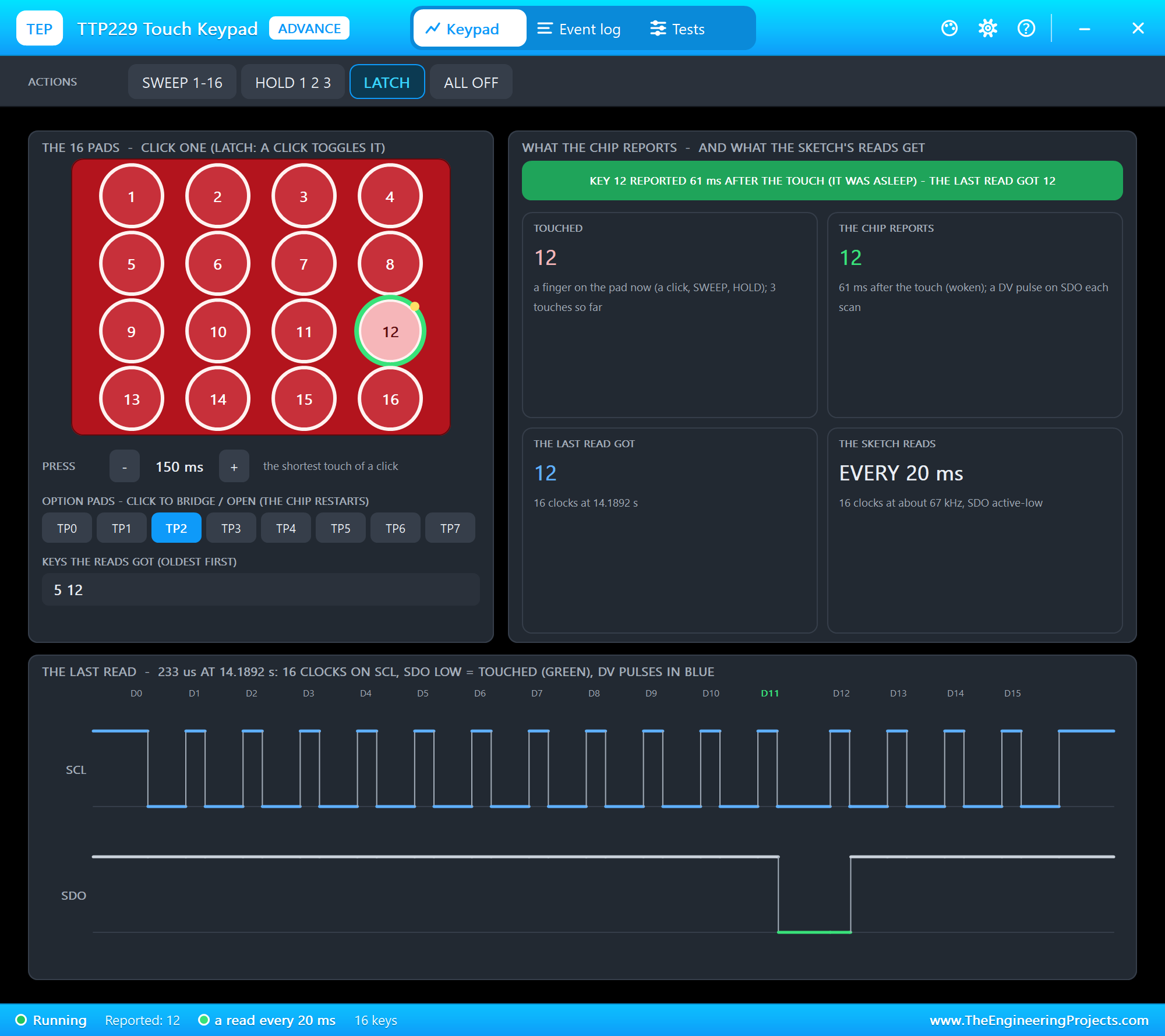
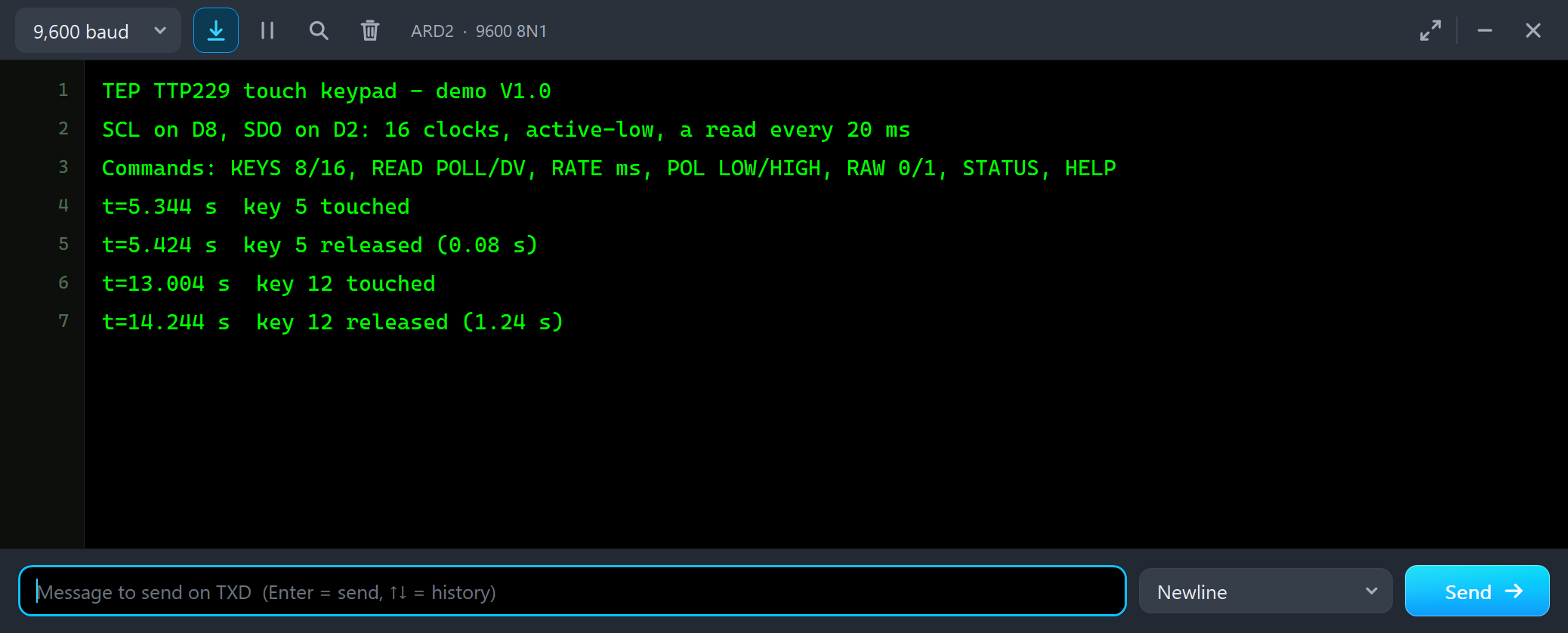
t=13.004 s  key 12 touched
t=14.244 s  key 12 released (1.24 s)
On a real board this is a drop of solder on TP2 - on many boards printed as pin 3 of the P1 group - and a power cycle.
Single-Key and Multi-Key
As the board comes, the TTP229 reports one key at a time: of several pads touched, the one with the lowest number wins. We clicked HOLD 1 2 3:
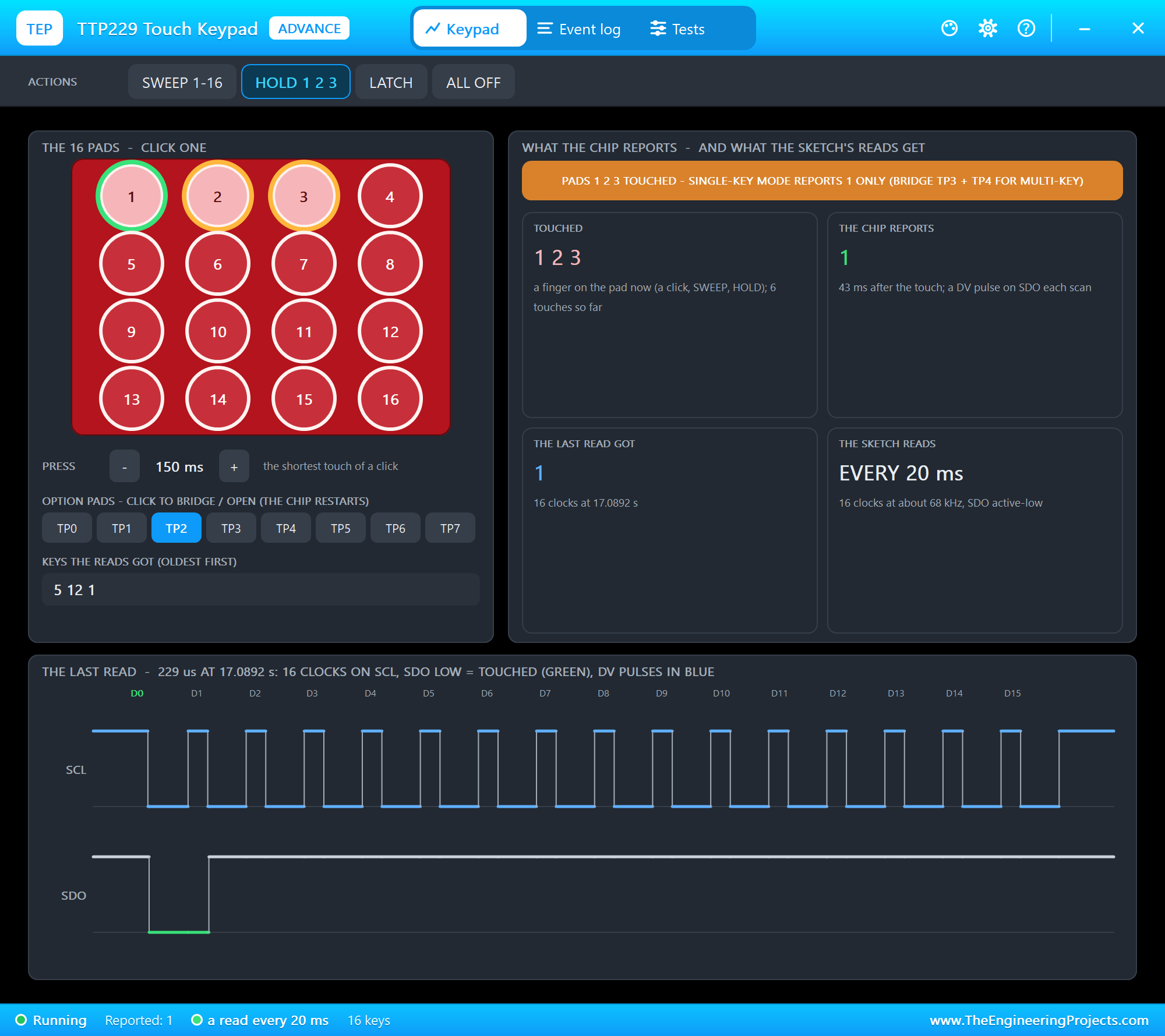
Three pads touched, one key reported. Bridging TP3 and TP4 switches the chip to multi-key (one of them alone makes two groups, each with its own rule). We clicked both and HOLD 1 2 3 again:
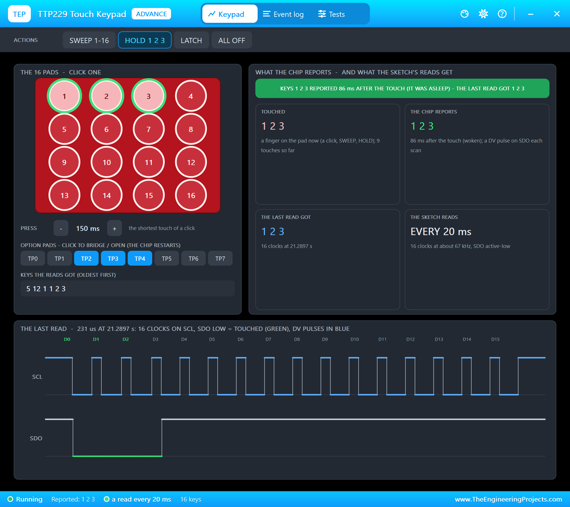
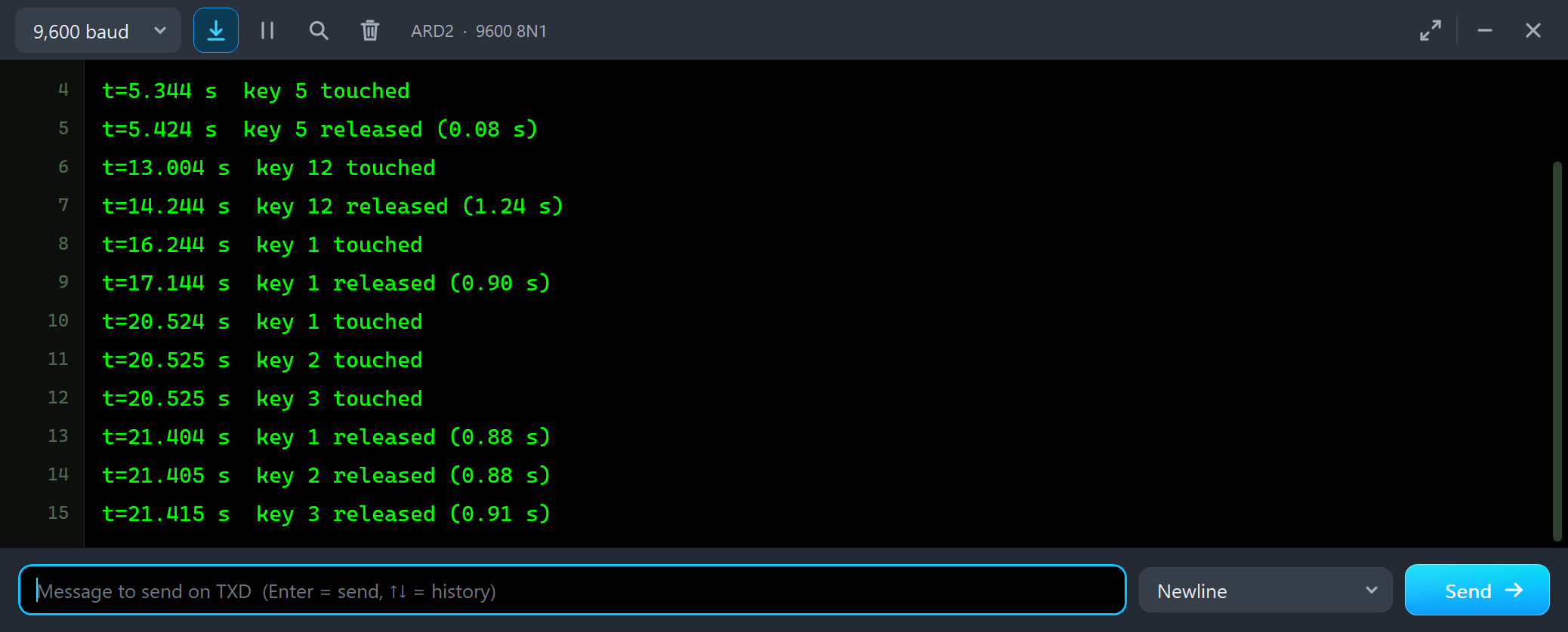
t=16.244 s  key 1 touched
t=17.144 s  key 1 released (0.90 s)
t=20.524 s  key 1 touched
t=20.525 s  key 2 touched
t=20.525 s  key 3 touched
t=21.404 s  key 1 released (0.88 s)
t=21.405 s  key 2 released (0.88 s)
t=21.415 s  key 3 released (0.91 s)
READ DV: the Data-Valid Pulse
Reading every 20 ms works, but the chip offers something smarter. While it reports a key it pulses SDO LOW for 93 us after each scan. We typed READ DV in ARD2's monitor and latched pad 7:
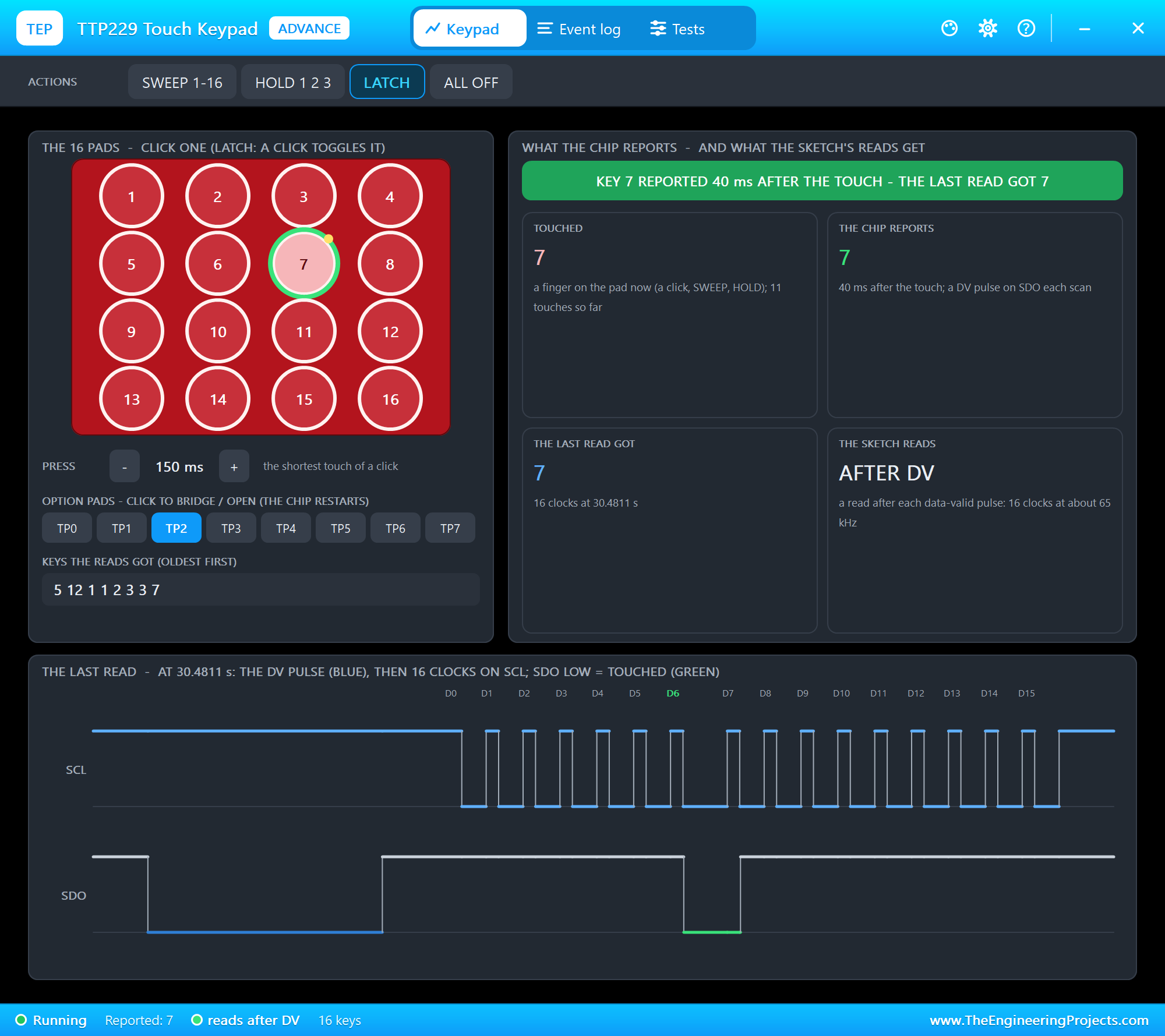
The last read now starts with the DV pulse in blue; about 30 us after it ends, the sketch clocks the 16 bits, and D6 - key 7 - is LOW. While the pad is held, a read follows every scan, 32 ms apart; when nothing is touched, nothing is read at all.
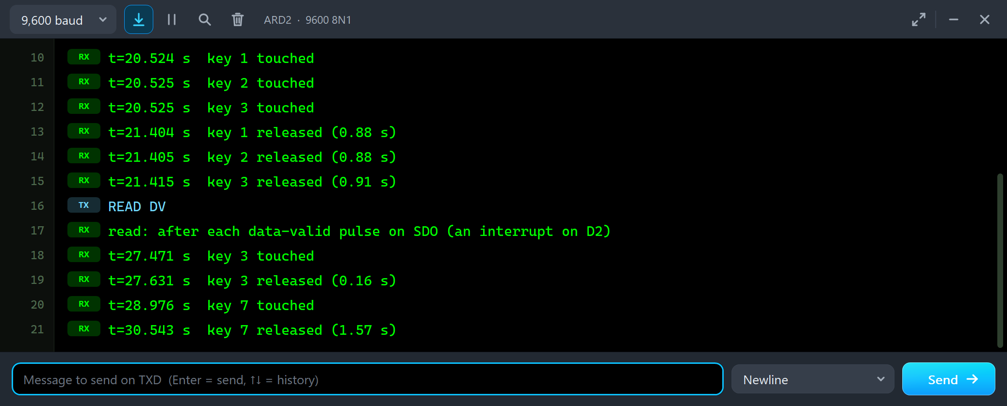
READ DV
read: after each data-valid pulse on SDO (an interrupt on D2)
t=27.471 s  key 3 touched
t=27.631 s  key 3 released (0.16 s)
t=28.976 s  key 7 touched
t=30.543 s  key 7 released (1.57 s)
Serial Read
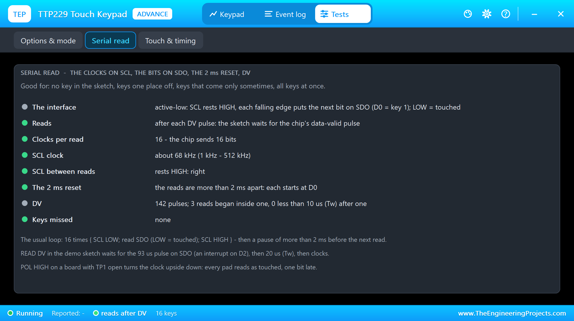
The Serial read tool judges the reader: how often it reads (or that it waits for DV), the clocks per read against the chip's bits, the clock frequency against the chip's 1 kHz - 512 kHz, the level SCL rests at, the 2 ms reset, the DV pulses and the keys no read got.
When the Reads Go Wrong
Four mistakes, one after the other. First RATE 1 - a read every millisecond - with pad 6 latched:
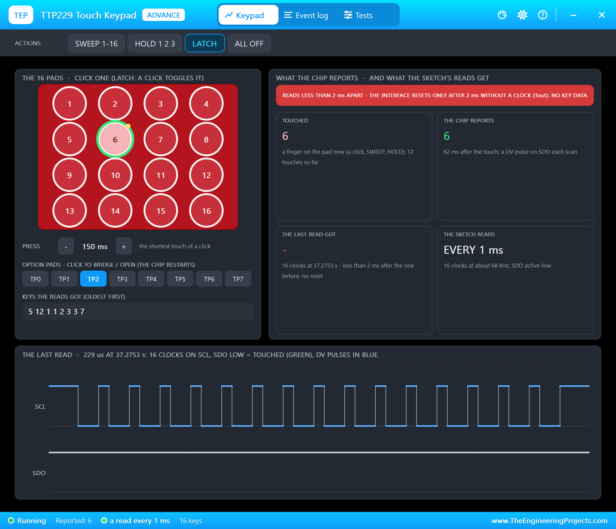
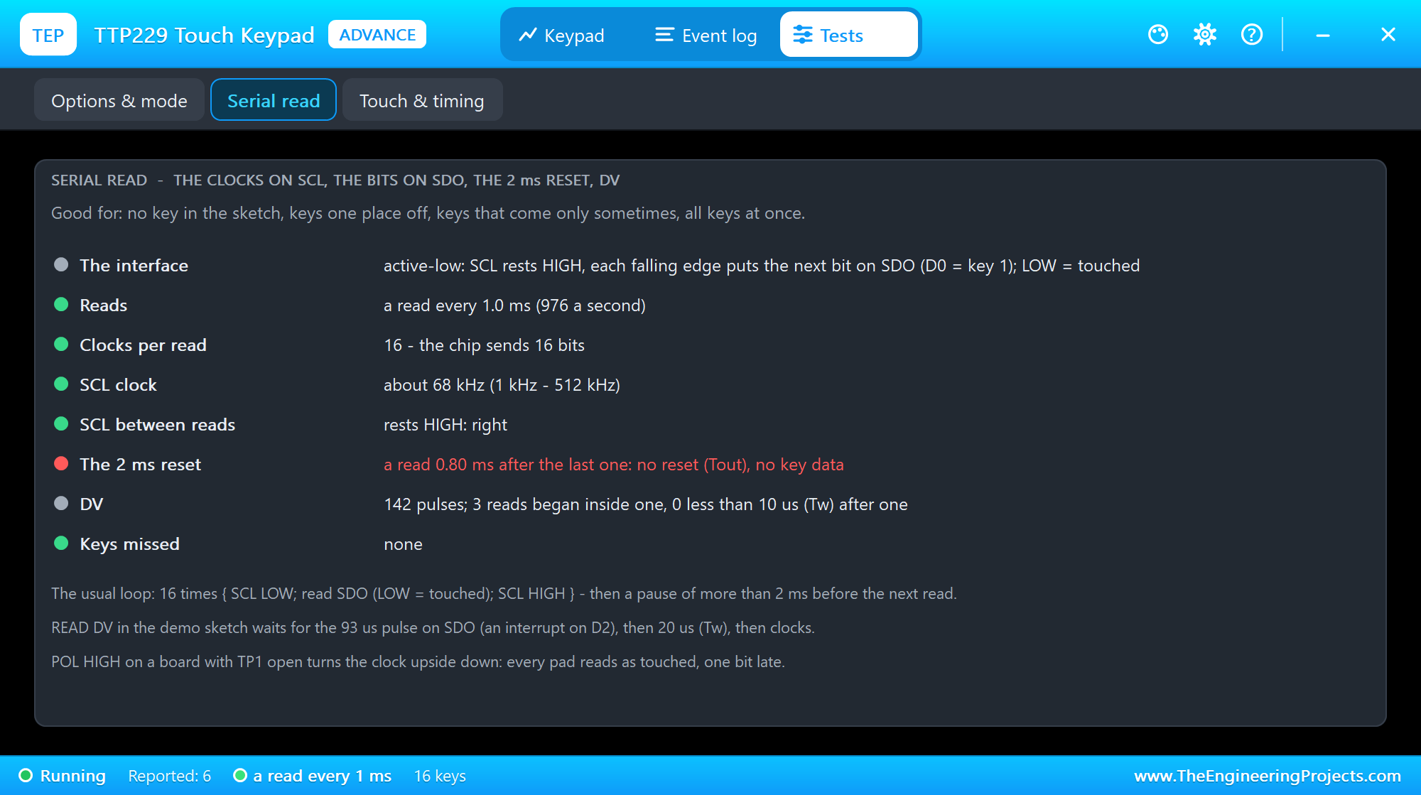
The chip reports key 6, but the sketch prints nothing: the reads come 1 ms apart, the interface never sees its 2 ms without a clock, so it never starts again at D0 - every read goes on after the last bit and gets the idle level. Keep more than 2 ms between two reads.
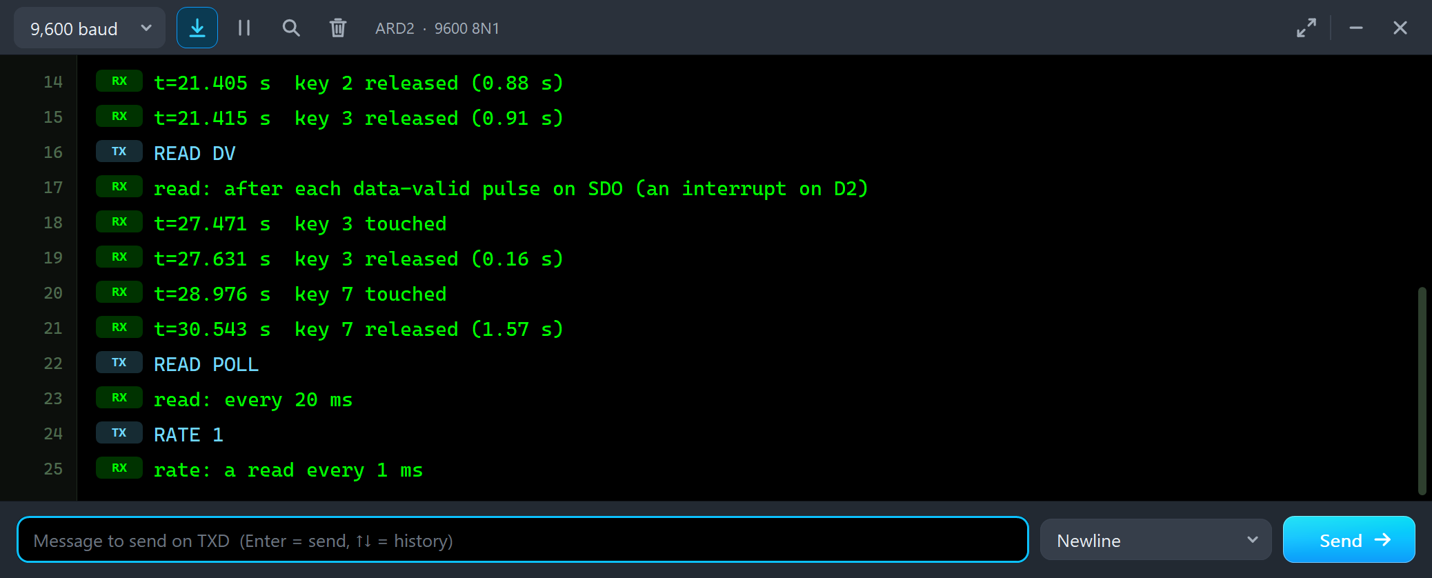
READ POLL
read: every 20 ms
RATE 1
rate: a read every 1 ms
RAW 1: the Bits on SDO
With RATE 20 back, RAW 1 prints the SDO bits of each new read. Pad 8:
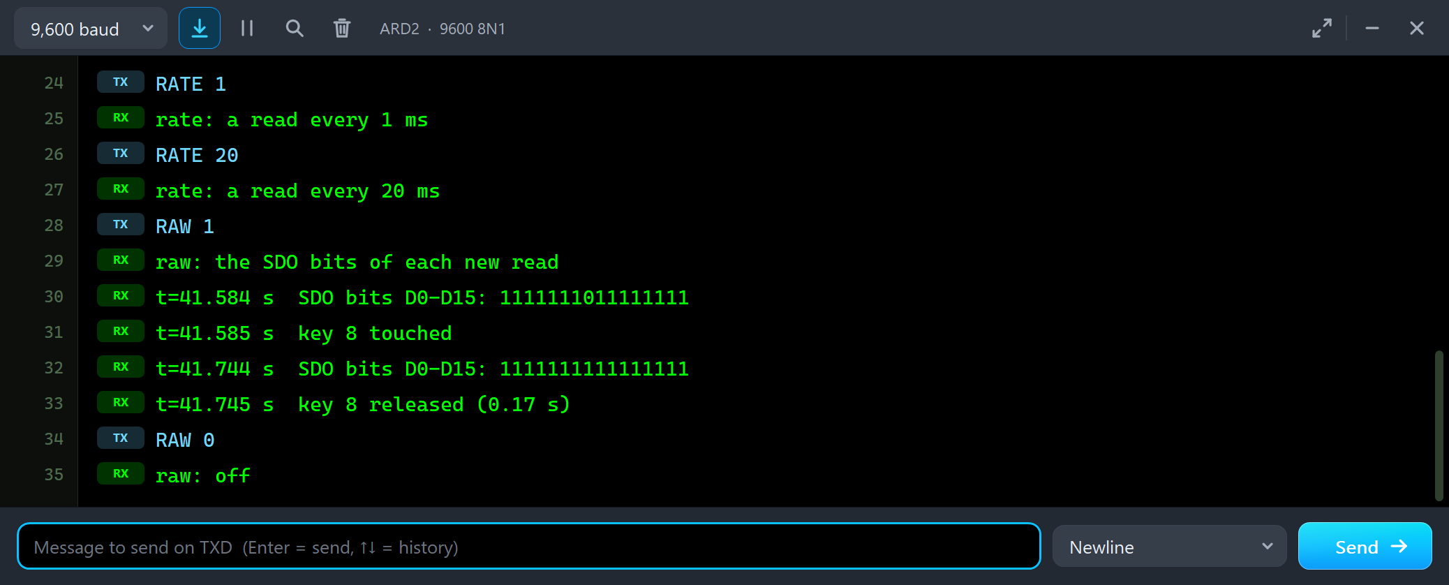
RAW 1
raw: the SDO bits of each new read
t=41.584 s  SDO bits D0-D15: 1111111011111111
t=41.585 s  key 8 touched
t=41.744 s  SDO bits D0-D15: 1111111111111111
t=41.745 s  key 8 released (0.17 s)
RAW 0
raw: off
Sixteen bits, D0 first. All are 1 - SDO HIGH, nothing touched - except D7: key 8, LOW, touched.
POL HIGH: the Clock Upside Down
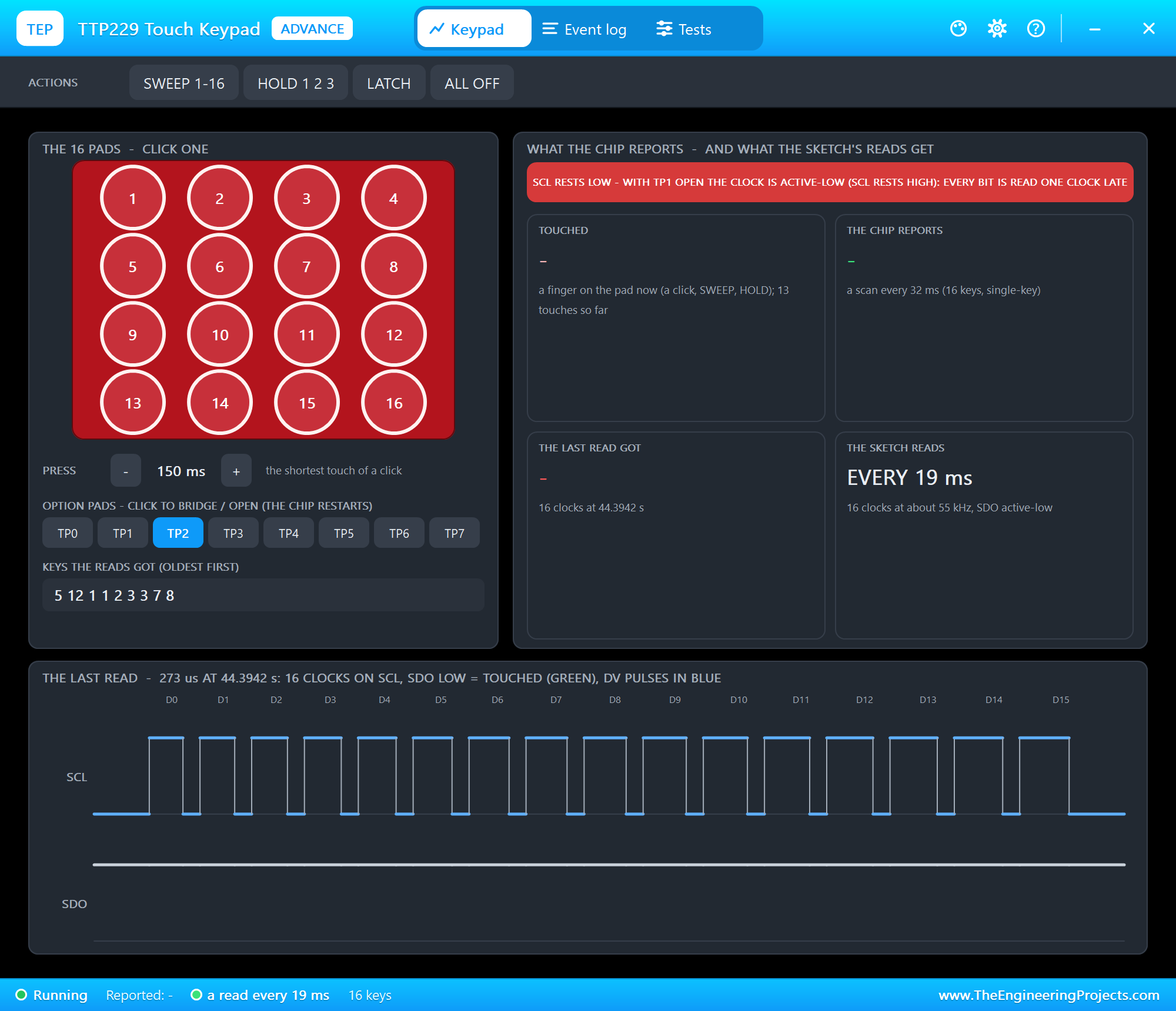
POL HIGH tells the sketch the board is active-high (TP1 bridged) - but it is not. The sketch now rests SCL LOW and reads HIGH as touched:
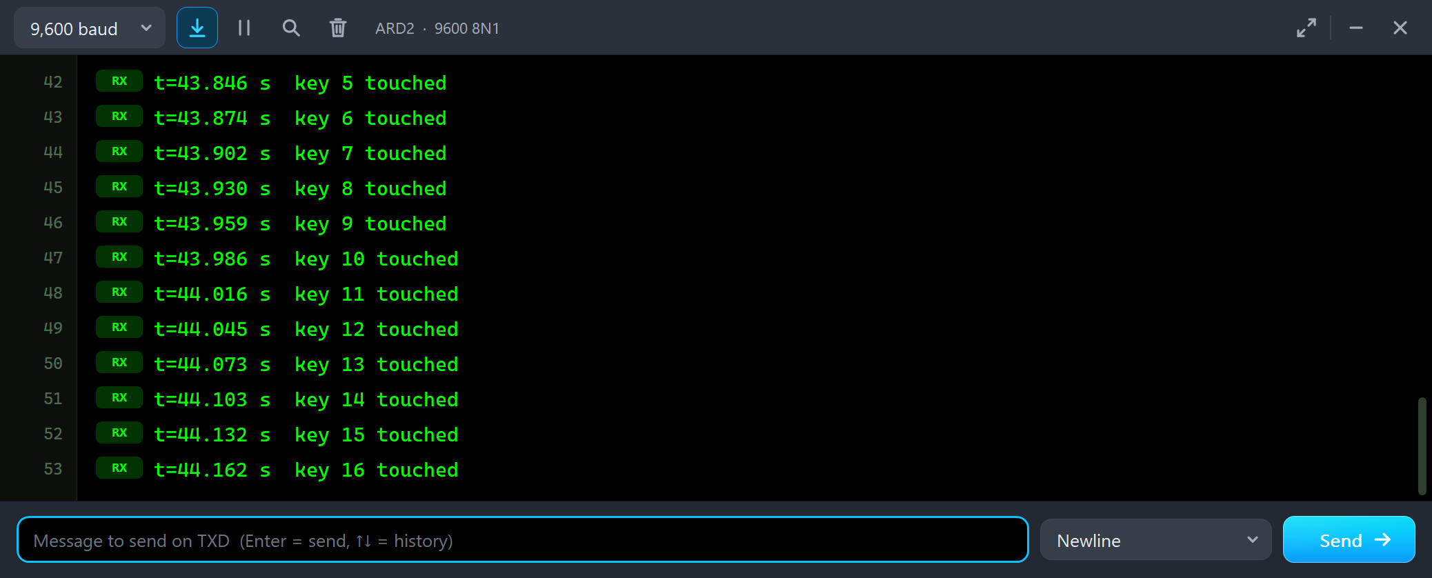
t=43.846 s  key 5 touched
t=43.874 s  key 6 touched
t=43.902 s  key 7 touched
t=43.930 s  key 8 touched
t=43.959 s  key 9 touched
t=43.986 s  key 10 touched
t=44.016 s  key 11 touched
t=44.045 s  key 12 touched
t=44.073 s  key 13 touched
t=44.103 s  key 14 touched
t=44.132 s  key 15 touched
t=44.162 s  key 16 touched
Every key reads as touched: the idle level is now taken as "touched", and each bit comes one clock late. The banner says it in one line. POL LOW put it right.
KEYS 8: a Short Read
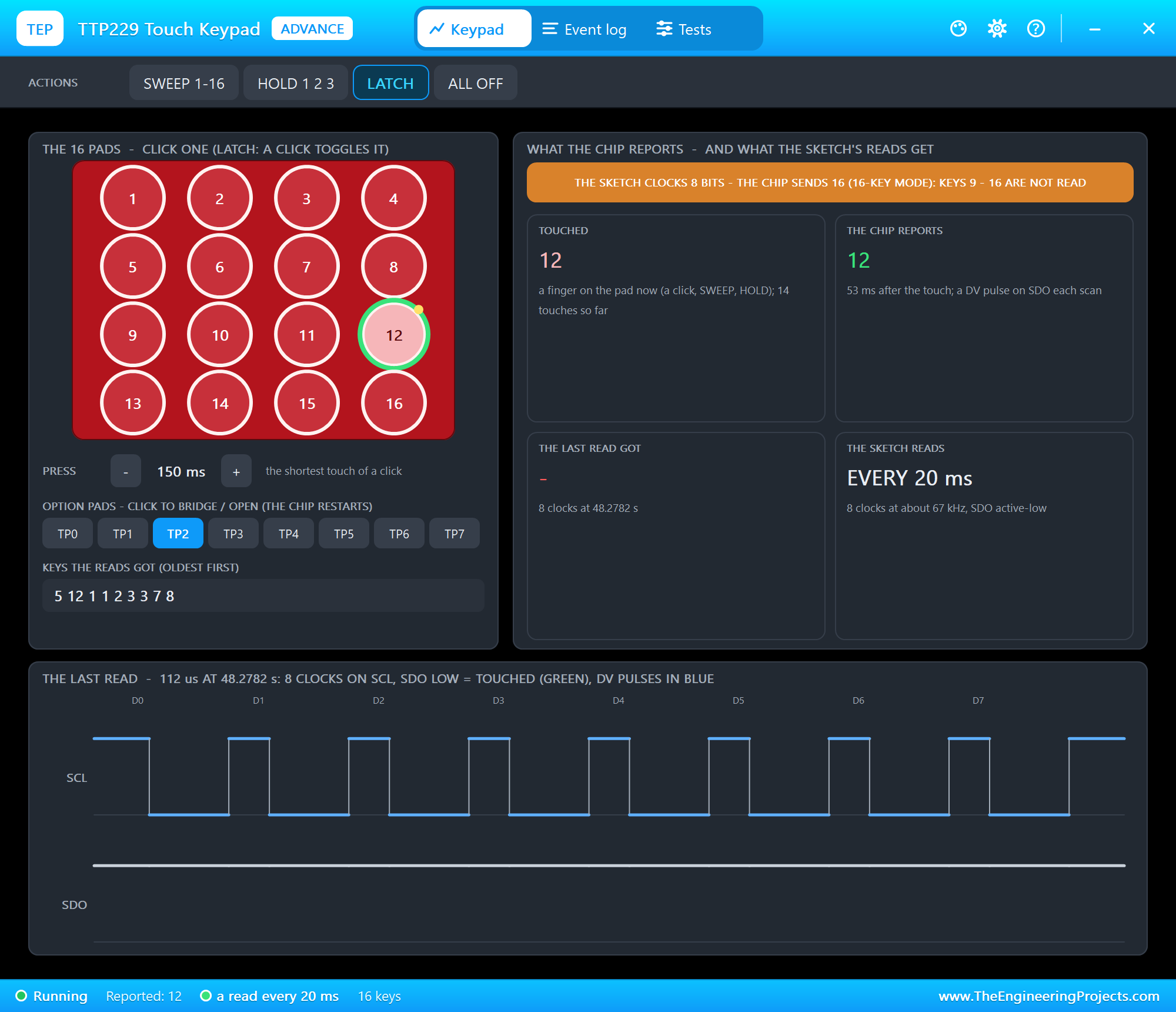
KEYS 8 makes the sketch clock only 8 bits. The chip reports key 12, the read never reaches D11, and the banner says so:
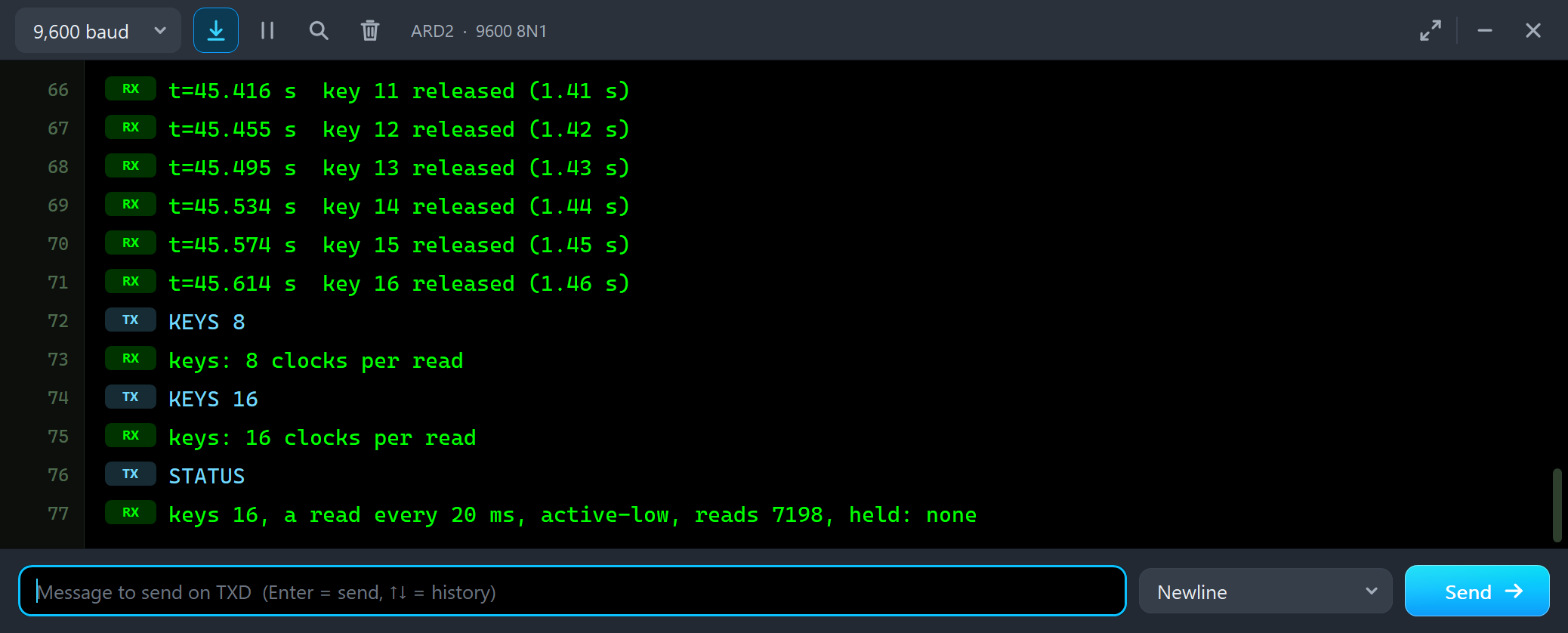
KEYS 8
keys: 8 clocks per read
KEYS 16
keys: 16 clocks per read
STATUS
keys 16, a read every 20 ms, active-low, reads 7198, held: none
SWEEP 1-16 and the Response Time
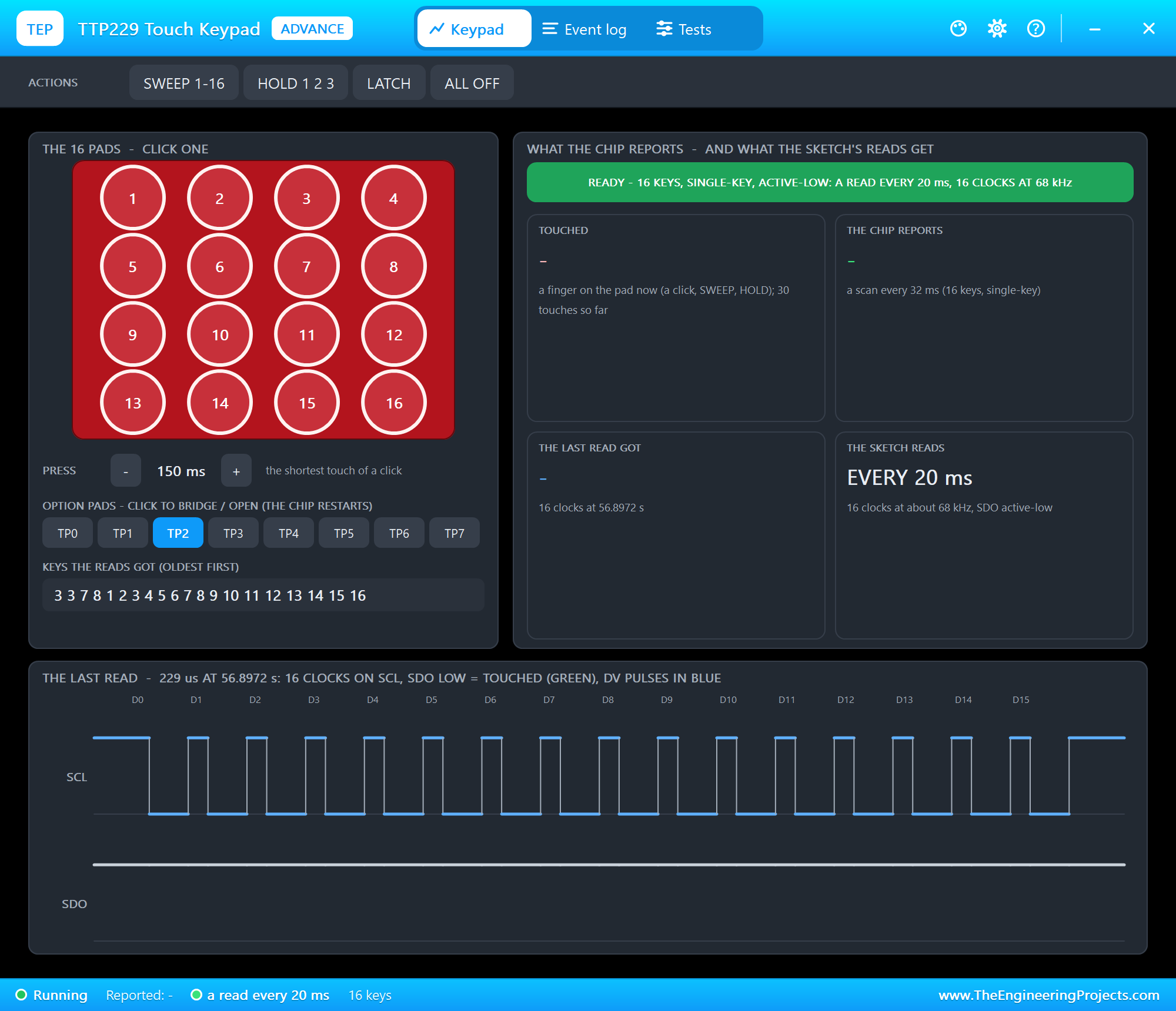
SWEEP 1-16 touched the pads one after the other, each for 150 ms. The chip reports a key only when a finger covers one whole scan - 32 ms with 16 keys - so each key came 32 - 64 ms after its touch, and the first touch after 8 s of rest up to 161 ms later, because the chip sleeps and wakes only 8 times a second.
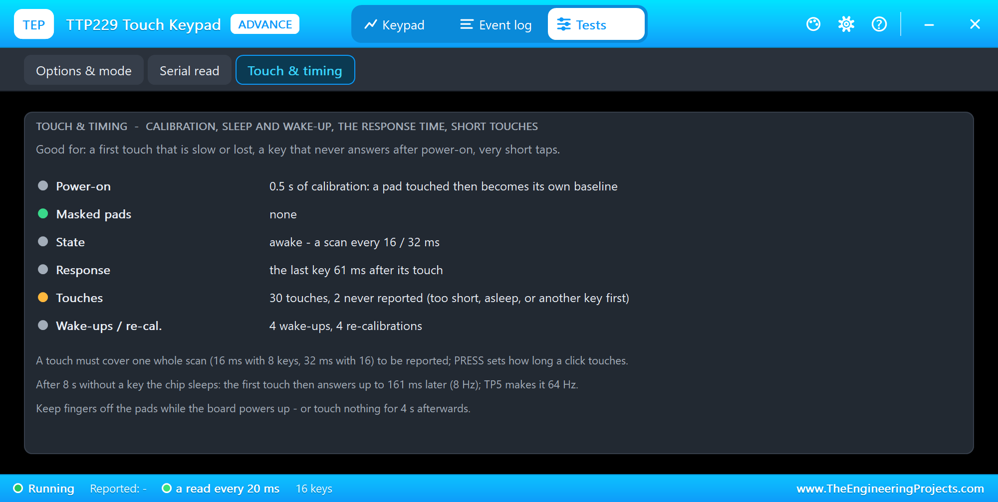
The Touch & timing tool shows the calibration, pads touched at power-on (they become their own baseline and answer again only after a re-calibration without the finger), sleep and wake-up, the last response time, and touches the chip never reported - too short, asleep, or another key first.
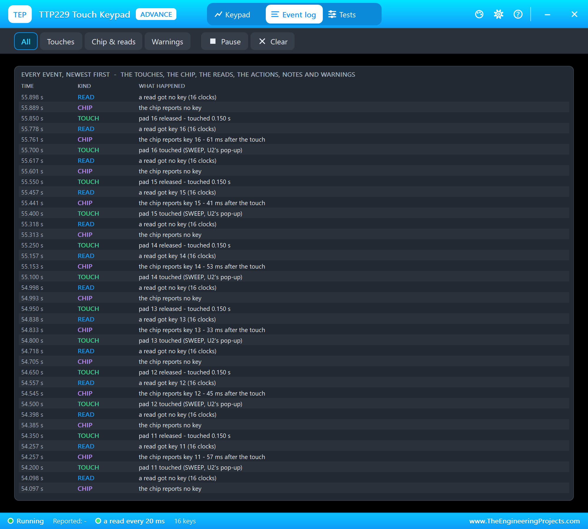
The Event log lists everything that happened, newest first: each touch and release, the chip's reports with their delay, the reads and what they got, the actions, notes and warnings. Filter it, pause it, or clear it.
The Board and the STATUS Panel with the Mouse
Back to node 1, the Simple board with TP2 bridged. We clicked its pads and its panel with the mouse while the simulation ran: pads 1, 6 and 16, then LATCH on the panel and pads 1 and 2:
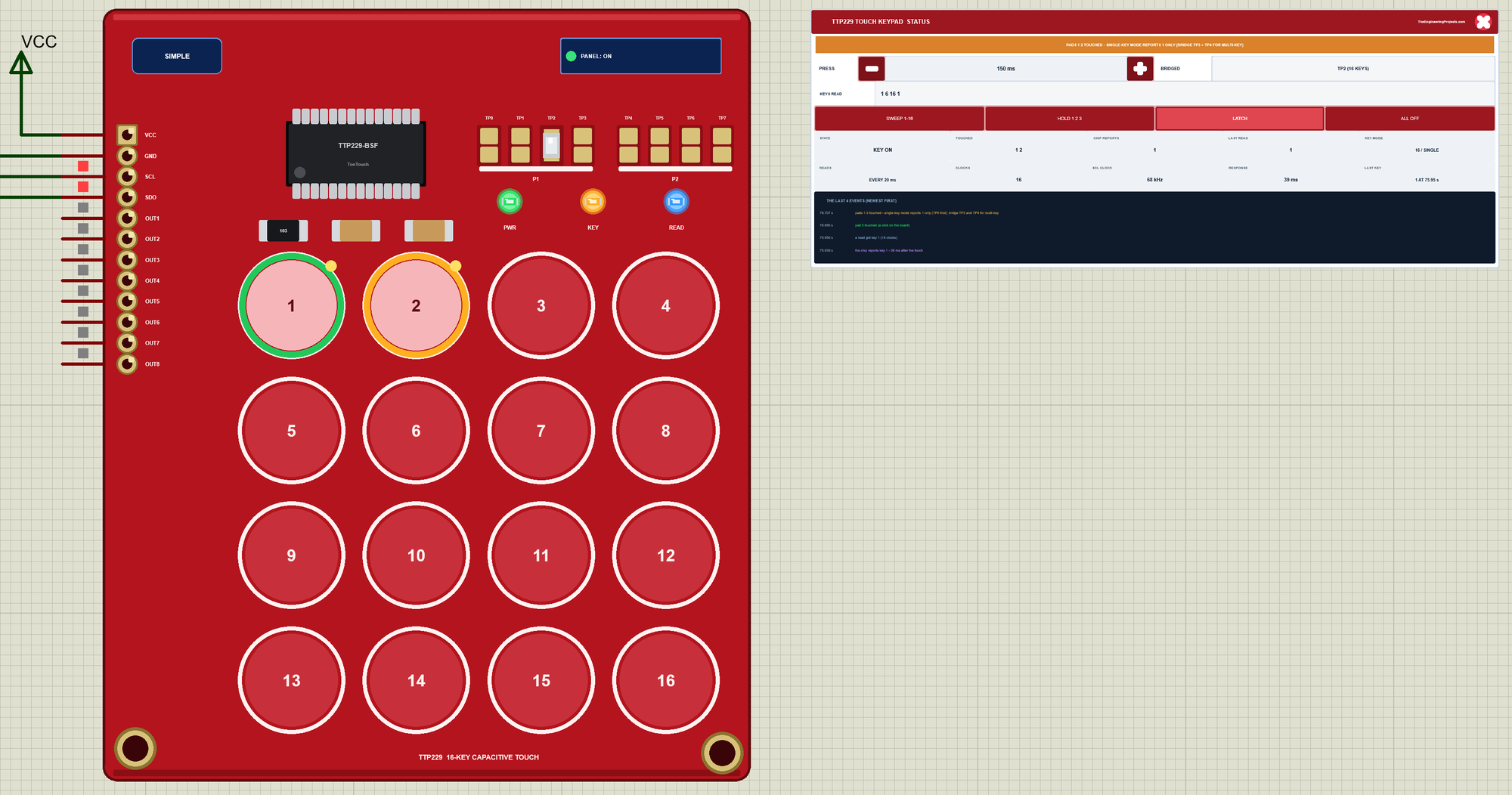
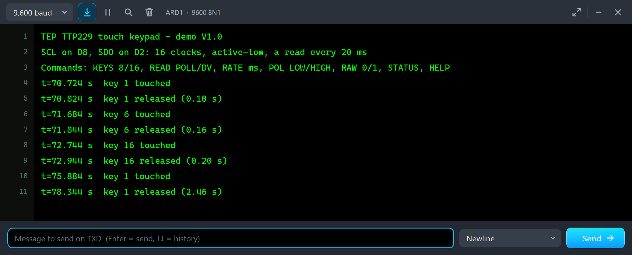
t=70.724 s  key 1 touched
t=70.824 s  key 1 released (0.10 s)
t=71.684 s  key 6 touched
t=71.844 s  key 6 released (0.16 s)
t=72.744 s  key 16 touched
t=72.944 s  key 16 released (0.20 s)
t=75.884 s  key 1 touched
t=78.344 s  key 1 released (2.46 s)
Then we clicked the option pads TP3 and TP4 on the board - each click restarts the chip - and HOLD 1 2 3 on the panel:
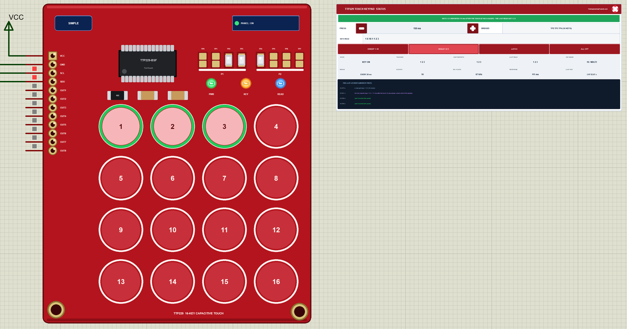
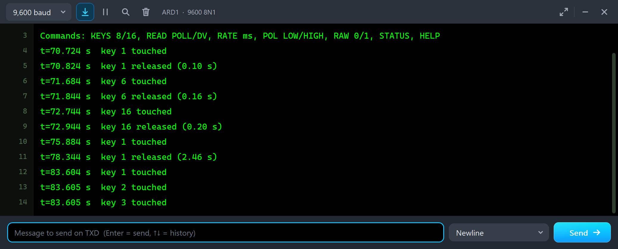
t=83.604 s  key 1 touched
t=83.605 s  key 2 touched
t=83.605 s  key 3 touched
Finally PRESS + and -, SWEEP 1-16 on the panel, and the red X and the PANEL button closed and reopened the STATUS panel:
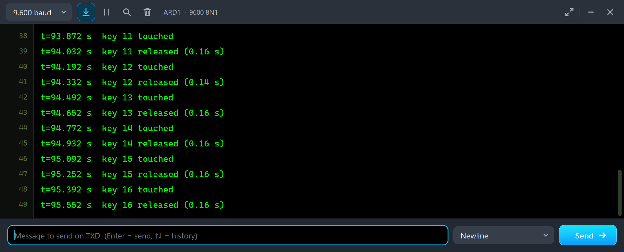
The Simulation Log
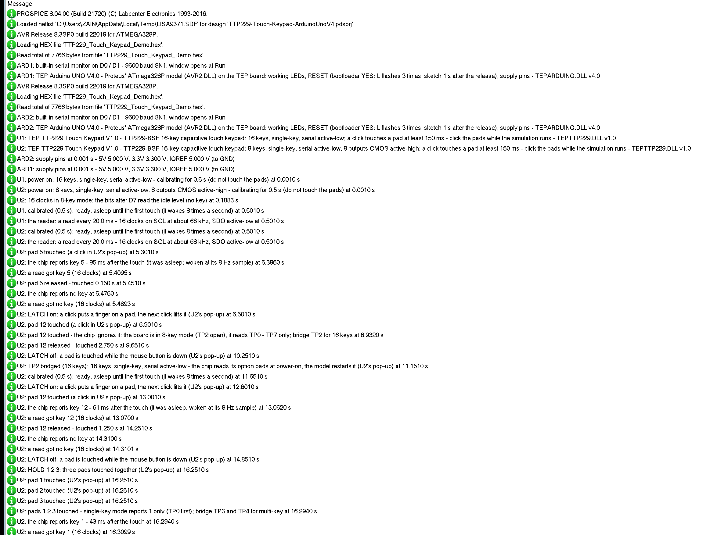
The boards also write to the simulation log of Proteus, with the exact simulation time. These lines show the start:
U1: TEP TTP229 Touch Keypad V1.0 - TTP229-BSF 16-key capacitive touch keypad: 16 keys, single-key, serial active-low; a click touches a pad at least 150 ms - click the pads while the simulation runs - TEPTTP229.DLL v1.0
U2: TEP TTP229 Touch Keypad V1.0 - TTP229-BSF 16-key capacitive touch keypad: 8 keys, single-key, serial active-low, 8 outputs CMOS active-high; a click touches a pad at least 150 ms - click the pads while the simulation runs - TEPTTP229.DLL v1.0
U2: power on: 8 keys, single-key, serial active-low, 8 outputs CMOS active-high - calibrating for 0.5 s (do not touch the pads) at 0.0010 s
U2: calibrated (0.5 s): ready, asleep until the first touch (it wakes 8 times a second) at 0.5010 s
U2: the reader: a read every 20.0 ms - 16 clocks on SCL at about 68 kHz, SDO active-low at 0.5010 s
U2: pad 5 touched (a click in U2's pop-up) at 5.3010 s
U2: the chip reports key 5 - 95 ms after the touch (it was asleep: woken at its 8 Hz sample) at 5.3960 s
U2: a read got key 5 (16 clocks) at 5.4095 s
U2: pad 12 touched - the chip ignores it: the board is in 8-key mode (TP2 open), it reads TP0 - TP7 only; bridge TP2 for 16 keys at 6.9320 s
Each board reports its options at the start, calibrates for 0.5 s, then names the reader it found - a read every 20.0 ms, 16 clocks at about 68 kHz - and logs every touch, the chip's report with its delay, and what the reads got.
How the Model Works
The TTP229 is a digital model. Each edge on SCL goes to the chip, which puts the next bit on SDO 0.3 us later - the key data it reported at the first clock after a reset. The chip's own events come at their exact times: the end of the calibration, the wake-up samples, the scans (a pad counts when a finger covers a whole scan), the re-calibration every 4 s without a key, the 93 us DV pulse, and the 2 ms timeout that resets the interface. From the clock edges alone the model learns the reader: how often it reads, how many clocks, how fast, at which level SCL rests, and whether it waits for DV.
Troubleshooting
- Keys 9 - 16 never answer: the board is in 8-key mode - bridge TP2.
- Only one of several pads comes: single-key mode - bridge TP3 and TP4 for multi-key.
- No key at all: nothing clocks SCL, the pins in the sketch are not the wired ones, or the reads come less than 2 ms apart - Serial read shows which.
- Every key reads as touched, or the keys come one place off: the clock is upside down - with TP1 open, SCL must rest HIGH.
- A key never answers after power-on: it was touched during the 0.5 s calibration - lift the finger and wait 4 s.
- A short tap gets lost: shorter than one scan, or the chip was asleep.
- No part or no monitor: TEPTTP229.DLL or TEPARDUINO.DLL is missing from MODELS and the project folder; a closed monitor opens again with a click on the UNO's USB port.
Things to Know Before Using a Real TTP229 Board
- 8 keys from the factory: bridge TP2 (on many boards P1 pin 3) for 16; TP3 and TP4 (P1 pin 4 and P2 pin 5) for multi-key; power the board again after a change.
- Hands off at power-up: a finger on a pad during the first half second becomes its baseline.
- Not I2C: SCL and SDO are plain digital pins - do not put them on A4 / A5 with the Wire library.
- Wait between reads: more than 2 ms, or the interface never resets.
- A cover: the pads work through thin plastic or glass; thicker covers need the chip's sensitivity capacitors changed.
Limitations of the Simulation
- Not modelled: the pads' capacitance and the touch's strength (a touch is on or off), the sensitivity capacitors and the cover, the supply current and the regulator, noise and water on the pads, a load on OUT1 - OUT8 in 16-key mode.
- The model's own choices: SDO 0.3 us after a clock edge; a touch counts when it covers a whole scan; a read sooner than 2 ms goes on where the last stopped; DV at each scan while a key is reported and once when the last key goes; PRESS, the SWEEP timing and the HOLD keys.
- The badge, the LEDs, the panel button and the panels are TEP additions.
- The model is our own implementation written from the TTP229-BSF datasheet. This library is not made or endorsed by Tontek, by the boards' makers or by Labcenter.
- Licences: the demo sketch uses no library; the HEX file contains the Arduino AVR core 1.8.6 with LGPL-licensed code - the source link is in the README.
- Tested in Proteus 8.5 in October 2026 (the demo as shipped on two Arduino UNO V4.0 boards with their built-in monitors: pad 5 and pad 12 in 8-key mode, TP2, HOLD 1 2 3 in single-key and multi-key mode, READ DV, RATE 1, RAW 1, POL HIGH, KEYS 8 and SWEEP 1-16 with the three tools on the Advance board; pads, LATCH, TP3 and TP4, HOLD 1 2 3, PRESS, SWEEP, the red X and PANEL with the mouse on the Simple one; 111.3 s of simulation took 276 s, about 0.40 x real time with the pop-up and both monitors open). Proteus 7 is not supported.
So, that was all about the TTP229 Touch Keypad Library for Proteus V1.0. I hope the option pads, the two-wire read and the DV pulse are clear now, and that your touch panel works from the first run. If you use the TTP229 Touch Keypad Library for Proteus in a project, please share it in the comments or in our forum, and if you have any questions, ask in the comments and I will help you out. Till the next tutorial, take care and have fun!
Comments
0