


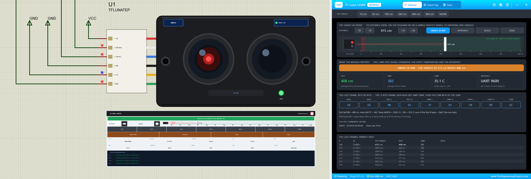
TF-Luna LiDAR Distance Sensor Library for Proteus V1.0


Hello friends, I hope you all are doing great. Today, I am going to share the new TF-Luna LiDAR Distance Sensor Library for Proteus V1.0. The TF-Luna from Benewake is a tiny single-point LiDAR: it shines modulated infrared light at a target and measures the distance from the reflection, from 20 cm to 8 m, up to 250 times a second. Robots use it to avoid walls, drones to hold their height, and makers to measure a tank, a door or a parking space. Now you can test those projects in Proteus.
Behind the part sits our own model, written from Benewake's manual. It has both interfaces - the UART with its 9-byte frames and its commands, and I2C with the register file and the data-ready pin - chosen by pin 5 at power-on, just like the real module. The signal strength falls with the distance and with a dark target, the module sends 0 when the signal is too weak, and close up it enters its dead zone. You move the target, pick a preset, sweep it, bring it closer, paint it black or put it on an edge. You get two devices: a Simple device with a live STATUS panel and an Advance device with a pop-up window and the test tools. The demo runs on our Arduino UNO V4.0.
NOTICE: a distance sensor is easy to fake: a number on a pin. We wanted more. Our TF-Luna speaks both of the real module's languages, frame by frame and register by register, so a sketch at the wrong baud rate, with the wrong pin 5, or one that trusts a reading of 0, fails exactly as it does with the real module. It took our team a lot of hard work. Your feedback is the fuel that keeps us going, so please tell us what you think in the comments below or in the TF-Luna board of our forum. And if our free libraries help you, you can buy us a coffee. So, let's get started with the TF-Luna LiDAR Distance Sensor Library for Proteus V1.0:
What is the TF-Luna?
The TF-Luna is a time-of-flight distance sensor in a small black box with two lenses: one sends near-infrared light, the other receives the reflection. Instead of timing a single pulse, it measures the phase difference between the modulated light it sends and the light that comes back, and turns that into a distance. It is a big brother of the little time-of-flight chips - see our VL53L0X Library for Proteus and the VL6180 time-of-flight proximity sensor - with a much longer reach. For laser and infrared sensing in general, read our Introduction to Laser Sensor.
| TF-Luna (the manual) | |
|---|---|
| Range | 0.2 to 8 m (90 % white target), 0.2 to 2.5 m (10 % black) |
| Accuracy | +-6 cm from 0.2 to 3 m, +-2 % from 3 to 8 m |
| Resolution | 1 cm |
| Field of view | 2 degrees |
| Frame rate | 1 to 250 Hz (500 / n), 100 Hz by default |
| Supply | 3.7 to 5.2 V, about 70 mA (150 mA peaks) |
| Signals | LVTTL (3.3 V) |
| Interfaces | UART 115200 baud (pin 5 open) or I2C at 0x10 (pin 5 to GND) |
| Devices | TFLUNATEP (Simple) and TFLUNAADVTEP (Advance) |
The Six Pins
| Pin | Name | UART (pin 5 open) | I2C (pin 5 to GND) |
|---|---|---|---|
| 1 | +5V | supply | supply |
| 2 | RXD/SDA | receives the commands | SDA |
| 3 | TXD/SCL | sends the frames | SCL |
| 4 | GND | ground | ground |
| 5 | CFG | open (or 3.3 V) | to GND |
| 6 | MUX | an on / off output (not modelled) | HIGH when new data is ready |
Pin 5 is read only at power-on: it decides whether pins 2 and 3 are a serial port or an I2C bus. Change it later and nothing happens until the module is powered again.
Amp, the Signal Strength
Every reading comes with Amp, the strength of the light that came back. It falls quickly with the distance and with a dark target, and when it drops below 100 the module no longer trusts its own distance and sends 0 instead - the dummy value. Our model gives Amp 100 at 8 m for a white target and at 2.5 m for a black one, and its noise follows the manual's table: about 3 cm at Amp 100 and 0.5 cm at Amp 2000 or more. The TF-Luna measures 500 times a second and averages them into frames, so a lower frame rate means a quieter reading.
What's New in TF-Luna LiDAR Distance Sensor Library for Proteus V1.0
- The real module: the black body with its two lenses - the transmitter shows a red light while it measures - and the 6-pin connector with its coloured cable. The body shows the interface it chose at power-on.
- Two styles: a Simple device with a STATUS panel and an Advance device with a pop-up window; the DATA LED and the panel button sit on the module's body.
- UART: 9-byte frames at 115200 baud (or any baud you set), with the checksum, and the manual's 0x5A commands with their answers - frame rate, trigger, format, baud rate, output on / off, address, save, restore and more.
- I2C: the register file at 0x10 - distance, Amp, temperature, version, mode, trigger, frame rate, thresholds - and pin 6 HIGH when new data is ready.
- The physics: Amp against the distance and the target, the dummy value under Amp 100, the manual's noise, the 20 cm dead zone and a spot on two surfaces.
- The target on the panel: the distance in 10 cm steps, seven presets (10, 50, 100, 200, 400, 800 cm and NONE) and four actions: SWEEP 20-800, APPROACH, BLACK and EDGE.
- Three test tools on the Advance device: Frames & commands, Registers, and Range & signal.
- A two-node demo on our Arduino UNO V4.0: one sketch for both interfaces - Wire for I2C, AltSoftSerial for the UART - with FPS, TRIG, CONT and RAW.
- A compact package: about 1.26 MB, without the C++ source code of the model.
Two Devices: Simple and Advance
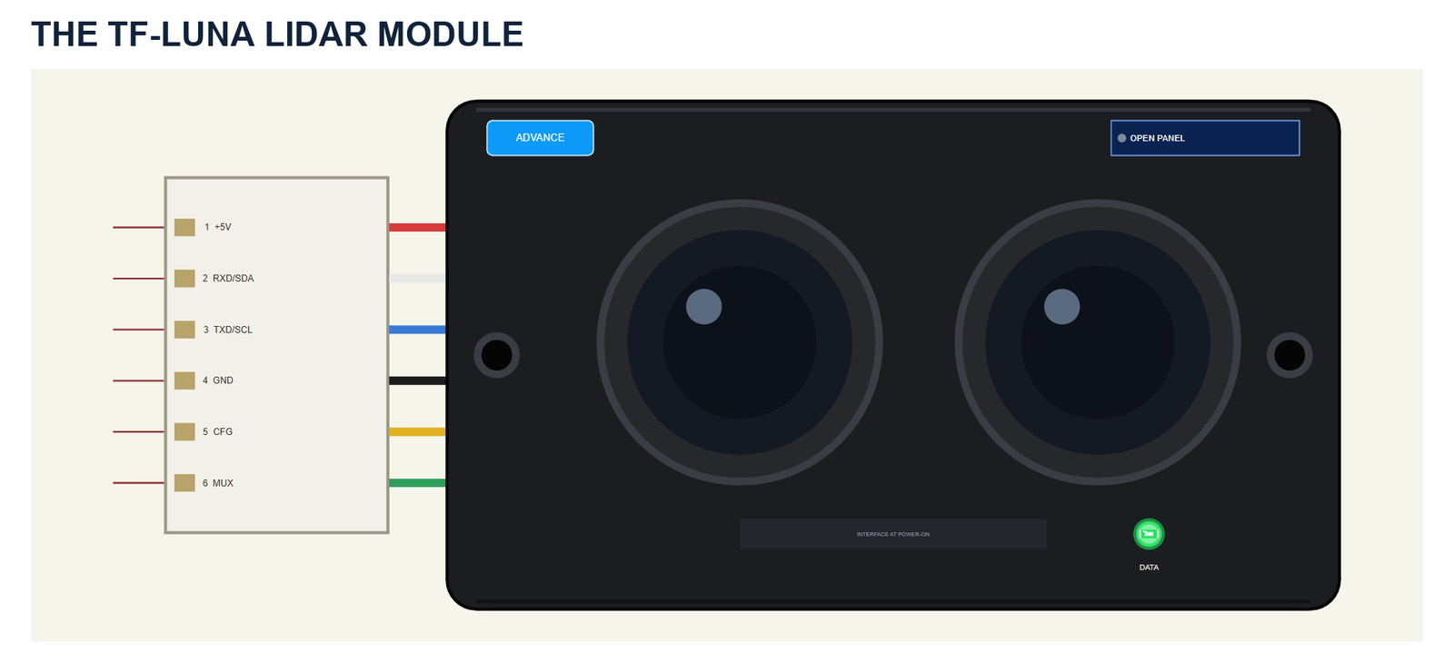
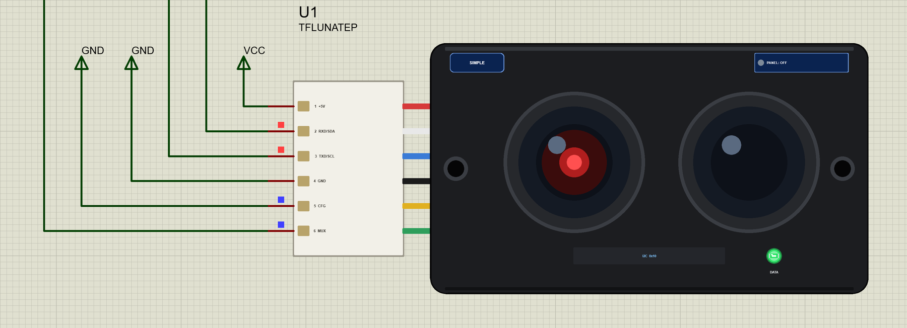
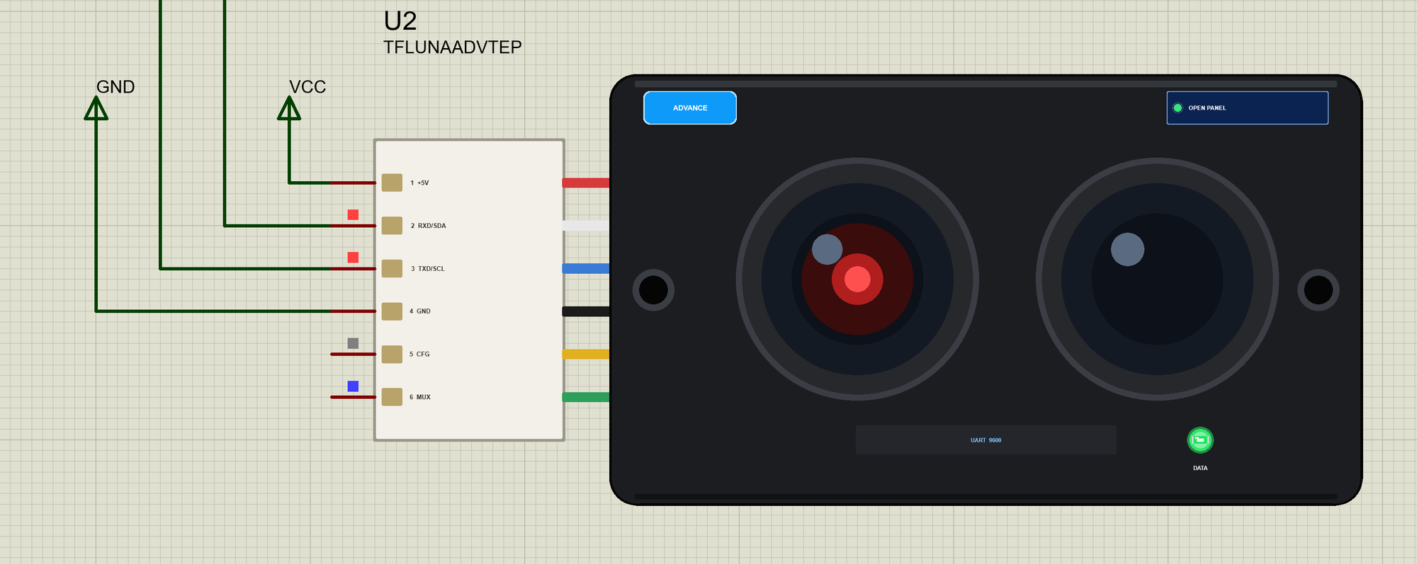
On the left is the connector with its six numbered wires; these are the part's pins. The big lens on the left is the transmitter, the one on the right the receiver. Under them a label shows the interface the module chose at power-on, and the DATA LED flashes with the frames. The module is drawn at about three times its real size, 35 x 21 mm.
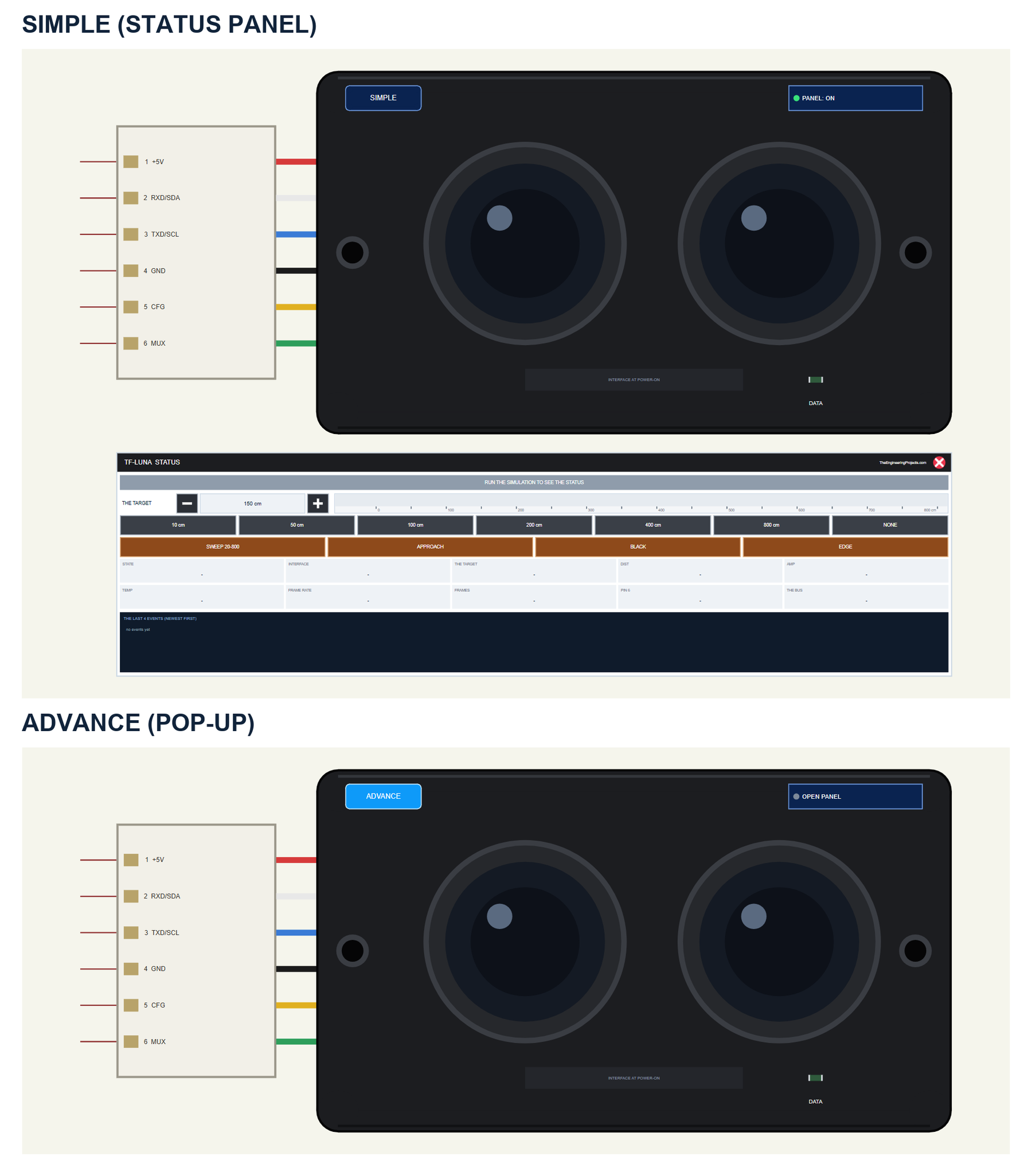
| Simple | Advance | |
|---|---|---|
| Device | TFLUNATEP | TFLUNAADVTEP |
| On the schematic | The module and the STATUS panel | The module |
| The target and the actions | On the STATUS panel | In the pop-up |
| Status | Banner, a ruler, 10 readouts, the last 4 events | A pop-up: Sensor, Event log, Tests |
Download TF-Luna LiDAR Sensor Library for Proteus
Click the button below to download TF-Luna-LiDAR-Library-for-Proteus-v1.0.zip (about 1.26 MB, without the C++ source code of the model):
TF-Luna LiDAR Distance Sensor Library for Proteus V1.0- README.txt: the devices, installation, the demo, wiring, the test tools and real hardware.
- Proteus Library Files:
TEPTFLUNA.LIBandArduinoV4TEP.LIBfrom our Arduino Library for Proteus V4.0. - Proteus Model Files:
TEPTFLUNA.DLLandTEPARDUINO.DLL. - Proteus Simulation:
TF-Luna-LiDAR-ArduinoUnoV4.pdsprj,TFLuna_LiDAR_Demo.hexand copies of the two DLLs. - Arduino Code:
TFLuna_LiDAR_Demo.ino- it needs AltSoftSerial from the Library Manager to rebuild it.
No Proteus yet? Read How to Download and Install Proteus 7 and 8. New to libraries? Follow How to Install a New Library in Proteus.
How to Install TF-Luna LiDAR Sensor Library for Proteus
- Close Proteus and extract the whole zip file, for example to your Desktop.
- Copy the two files from Proteus Library Files into the LIBRARY folder of Proteus (usually
C:\Program Files (x86)\Labcenter Electronics\Proteus 8 Professional\LIBRARY). - Copy
TEPTFLUNA.DLLandTEPARDUINO.DLLfrom Proteus Model Files into the MODELS folder. - Delete
TEPTFLUNA.IDXfrom the LIBRARY folder if it is there. - Start Proteus, press P and search for TFLUNA.
Tip: keep the Proteus Simulation folder together, because the project needs its .hex file and the DLLs beside it. The library is tested in Proteus 8.5; Proteus 7 is not supported.
The TF-Luna Parts in Proteus
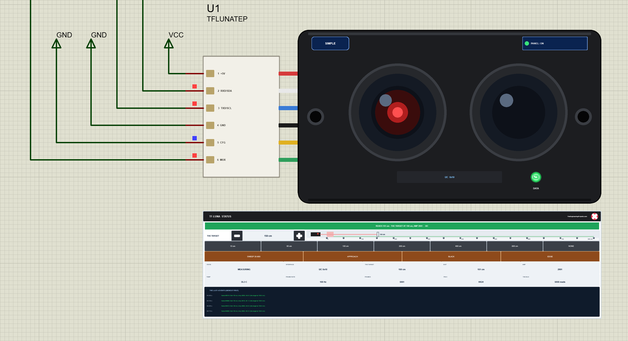
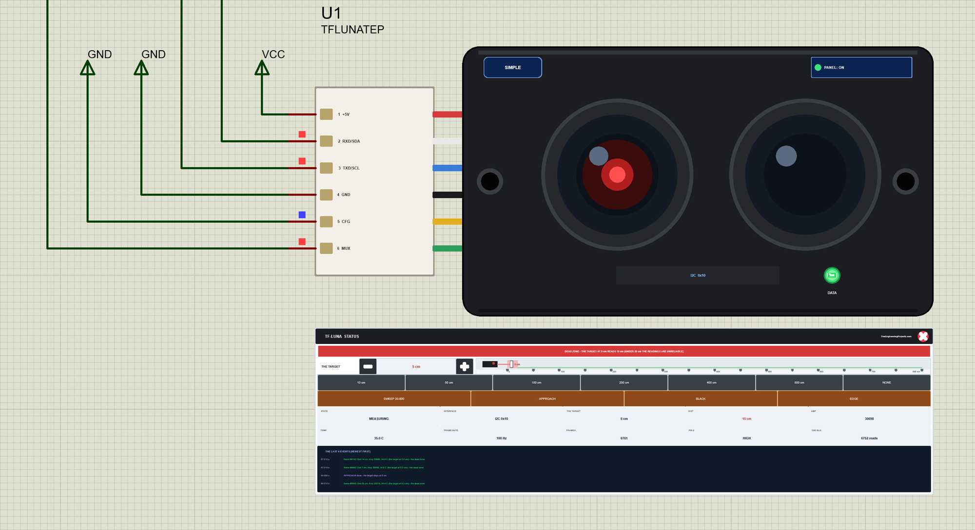
Look at the pins: CFG is LOW (blue), so the module chose I2C, and the label on its body says I2C 0x10. MUX is HIGH (red) between the reads: new data is waiting. The red light in the left lens shows that it measures, and DATA flashes with the frames. The LED, the badge, the label, the button and the panels are TEP additions; the real module has none of them, and its light is infrared, so you would not see it.
The Simple device adds the STATUS panel. Its banner says what the module reads, where the target really is and the signal; it turns amber when the signal is too weak or nothing is there, and red in the dead zone. Below it are the controls: THE TARGET with - and + (10 cm a click) and a ruler from 0 to 800 cm; seven presets - 10, 50, 100, 200, 400, 800 cm and NONE; and four actions - SWEEP 20-800, APPROACH, BLACK and EDGE. Ten readouts follow - the state, the interface, the target, Dist, Amp, the temperature, the frame rate, the frames, pin 6 and the bus - and the last four events.
The red X closes the STATUS panel, and the PANEL button on the module opens it again:
The Advance device keeps the schematic clean: only the module. Its live data opens in a pop-up window at Run, and the OPEN PANEL button on the body brings the window back. The properties set the start: DISTANCE (the target in cm, 0 for nothing), TARGET (WHITE or BLACK), FPS, BAUD and ADDR (what a real module has saved) and TEMP (the chip, 35 C).
The Demo Circuit
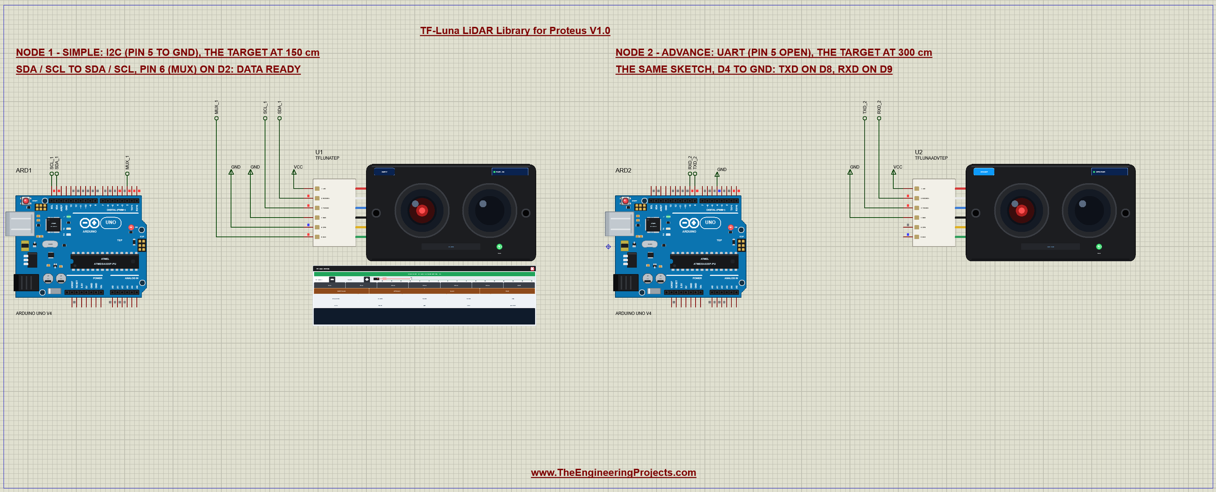
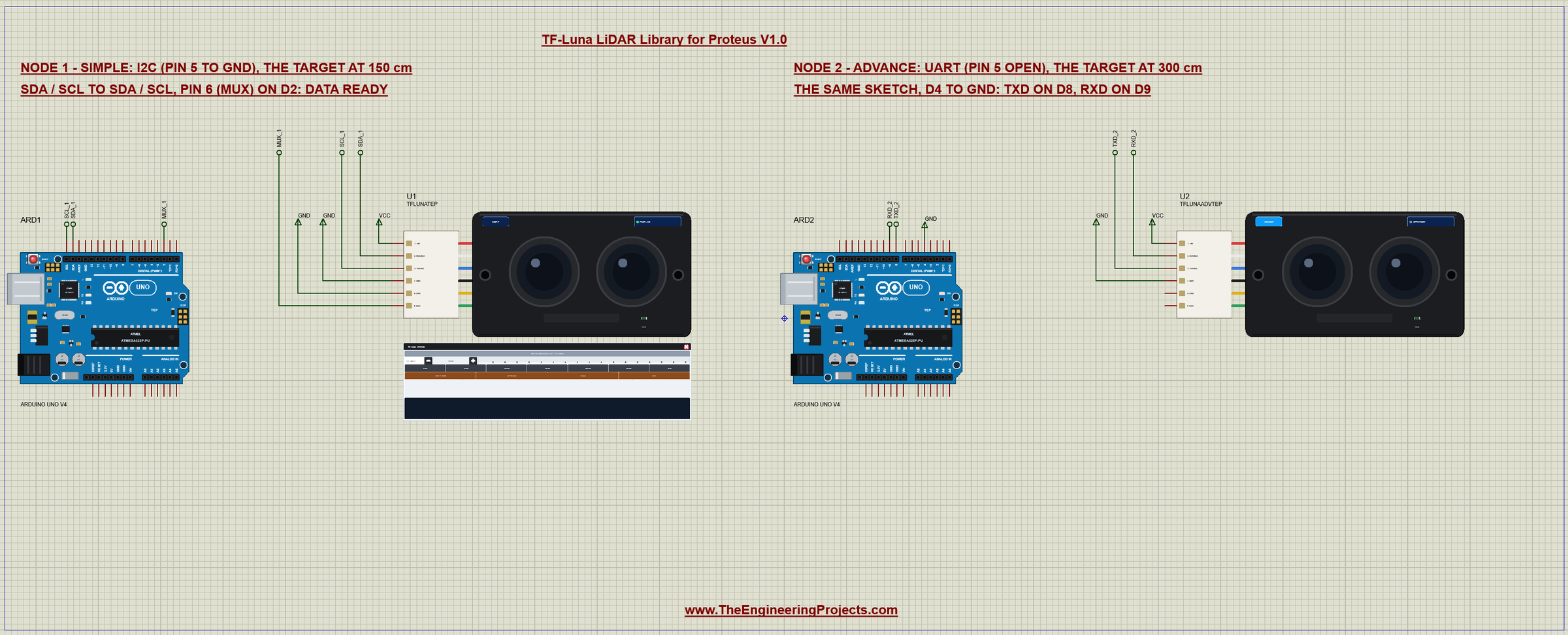
The demo project has two nodes, each an Arduino UNO V4.0 from our Arduino UNO Library for Proteus V4.0 with a TF-Luna. Node 1 uses I2C: its CFG pin goes to GND, SDA and SCL go to the UNO's SDA and SCL, and pin 6 goes to D2; the target is at 150 cm. Node 2 uses the UART: CFG stays open, the module's TXD goes to D8 and its RXD to D9, and the UNO's D4 goes to GND to tell the sketch; the target is at 300 cm. Both UNOs run the same TFLuna_LiDAR_Demo.hex.
Wiring
| TF-Luna | I2C (pin 5 to GND) | UART (pin 5 open) |
|---|---|---|
| 1 +5V | 5V | 5V |
| 2 RXD/SDA | SDA (A4) | D9 (AltSoftSerial TX) |
| 3 TXD/SCL | SCL (A5) | D8 (AltSoftSerial RX) |
| 4 GND | GND | GND |
| 5 CFG | GND | open |
| 6 MUX | D2 (data ready) | - |
Why AltSoftSerial on D8 and D9? The UNO has only one hardware serial port, and the monitor uses it. AltSoftSerial by Paul Stoffregen gives a second one with exact timing (see also How to use Arduino Software Serial), but it cannot receive 115200 baud on an UNO. So the sketch first tells the TF-Luna, at 115200, to talk at 9600 baud and to send 10 frames a second, and does not save it. In Proteus the pins reach their UNO through net labels - SDA_1, SCL_1 and MUX_1 for node 1, RXD_2 and TXD_2 for node 2 - and the serial monitor needs no wires at all, because it is built into the UNO V4.0.
The Arduino Code
One sketch reads both interfaces. New to Arduino? Start with Arduino Tutorial for Beginners and Introduction to Arduino UNO; for the idea of an I2C bus, see I2C Communication with STM32. The sketch uses two libraries:
#include <Wire.h>
#include <AltSoftSerial.h>
const uint8_t MUX_PIN = 2, MODE_PIN = 4, ADDR = 0x10;At the start it reads D4 to know which interface it has:
uartMode = digitalRead(MODE_PIN) == LOW;The UART: Commands and Frames
A command is 0x5A, the length, an ID, the data and a checksum - the low byte of the sum of the bytes before it:
void sendCmd(uint8_t* b, uint8_t n) {
  uint8_t sum = 0;
  for (uint8_t i = 0; i < n - 1; i++) sum += b[i];
  b[n - 1] = sum;
  for (uint8_t i = 0; i < n; i++) lidar.write(b[i]);
  lidar.flushOutput();
}
In setup() the sketch sends the baud rate command (ID 0x06) at 115200, waits, switches itself to 9600 and sets 10 frames a second (ID 0x03):
    lidar.begin(115200);                         // the TF-Luna starts at 115200 baud
    uint8_t b9600[] = {0x5A, 0x08, 0x06, 0x80, 0x25, 0x00, 0x00, 0};
    sendCmd(b9600, sizeof b9600);                // ... tell it 9600
    delay(20);
    lidar.end();
    lidar.begin(9600);
    setRate(10);                                 // 10 frames a second at 9600 baud
A frame is nine bytes: 0x59 0x59, Dist, Amp and Temp, two bytes each with the low byte first, and the low byte of the sum of the first eight. The sketch keeps the last nine bytes it received and accepts them only when they start with 59 59 and the sum checks:
void readFrames() {
  while (lidar.available()) {
    const uint8_t b = lidar.read();
    if (nWin < 9) win[nWin++] = b;
    else { memmove(win, win + 1, 8); win[8] = b; }
    if (nWin < 9 || win[0] != 0x59 || win[1] != 0x59) continue;
    uint8_t sum = 0;
    for (uint8_t i = 0; i < 8; i++) sum += win[i];
    if (sum != win[8]) continue;
    memcpy(frame, win, 9);
    dist = frame[2] | frame[3] << 8;
    amp = frame[4] | frame[5] << 8;
    tempC = (frame[6] | frame[7] << 8) / 8.0 - 256;
    have = true; frames++; nWin = 0;
  }
}
I2C: the Registers and Pin 6
Over I2C the TF-Luna is a set of registers at address 0x10. The distance is at 0x00, Amp at 0x02 and the temperature at 0x04 in hundredths of a degree, so one read of six bytes gets all three:
bool readRegs(uint8_t reg, uint8_t* b, uint8_t n) {
  Wire.beginTransmission(ADDR); Wire.write(reg);
  if (Wire.endTransmission() != 0) return false;
  if (Wire.requestFrom(ADDR, n) != n) return false;
  for (uint8_t i = 0; i < n; i++) b[i] = Wire.read();
  return true;
}
void readData() { // when pin 6 says new data is ready
uint8_t b[6];
if (!readRegs(0x00, b, 6)) return;
dist = b[0] | b[1] << 8;
amp = b[2] | b[3] << 8;
tempC = int16_t(b[4] | b[5] << 8) / 100.0;
have = true; frames++;
}The sketch does not poll blindly: pin 6 goes HIGH when a new measurement is ready and LOW once it has been read, so loop() reads only then:
  if (uartMode) readFrames();
  else if (digitalRead(MUX_PIN) == HIGH) readData();
FPS, TRIG and CONT
The frame rate is a command over the UART and a register over I2C. A rate of 0 means trigger mode: the module measures only when asked:
void setRate(uint16_t hz) {                      // 0 = trigger mode
  if (uartMode) {
    uint8_t c[] = {0x5A, 0x06, 0x03, uint8_t(hz & 0xFF), uint8_t(hz >> 8), 0};
    sendCmd(c, sizeof c);
  } else if (hz == 0) {
    writeReg(0x23, 0x01);                        // MODE: trigger
  } else {
    writeReg(0x23, 0x00);                        // MODE: continuous
    Wire.beginTransmission(ADDR); Wire.write(0x26); Wire.write(uint8_t(hz & 0xFF)); Wire.write(uint8_t(hz >> 8)); Wire.endTransmission();
  }
}
void trigger() {
if (uartMode) { uint8_t c[] = {0x5A, 0x04, 0x04, 0}; sendCmd(c, sizeof c); }
else writeReg(0x24, 0x01); // TRIG_ONE_SHOT
}The HEX file is in the package, so you do not need the Arduino IDE to run the demo. To change the sketch, install AltSoftSerial from the Library Manager and export the compiled binary, as in How to get the HEX file from Arduino. It needs 12,418 bytes of flash and 724 bytes of RAM.
The Serial Monitor
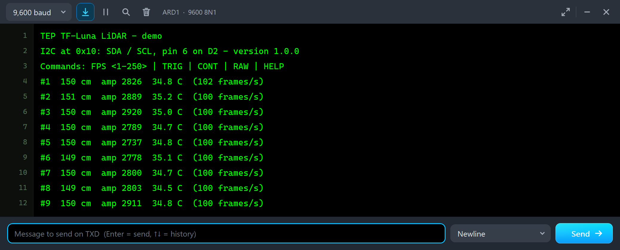
Both UNOs have the serial monitor built in, and it opens at Run. The screenshots use its Simple interface. Node 1, in I2C, first reads the version registers, then prints the latest reading twice a second:
TEP TF-Luna LiDAR - demo
I2C at 0x10: SDA / SCL, pin 6 on D2 - version 1.0.0
Commands: FPS <1-250> | TRIG | CONT | RAW | HELP
#1  150 cm  amp 2826  34.8 C  (102 frames/s)
#2  151 cm  amp 2889  35.2 C  (100 frames/s)
#3  150 cm  amp 2920  35.0 C  (100 frames/s)
#4  150 cm  amp 2789  34.7 C  (100 frames/s)
The target is at 150 cm and the readings stay at 149 to 151 cm: at Amp 2800 the noise is under a centimetre. The sketch counts about 100 frames a second - one read for each time pin 6 rose. Node 2, in UART, prints the nine bytes of each frame:
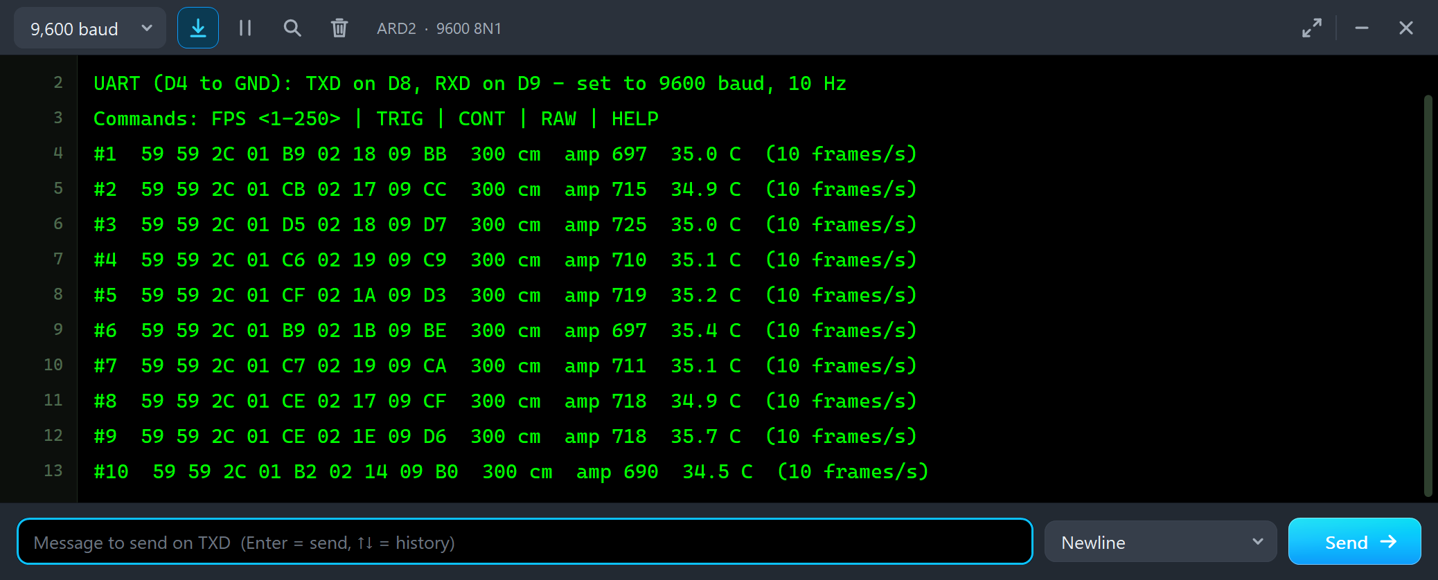
UART (D4 to GND): TXD on D8, RXD on D9 - set to 9600 baud, 10 Hz
Commands: FPS <1-250> | TRIG | CONT | RAW | HELP
#1  59 59 2C 01 B9 02 18 09 BB  300 cm  amp 697  35.0 C  (10 frames/s)
#2  59 59 2C 01 CB 02 17 09 CC  300 cm  amp 715  34.9 C  (10 frames/s)
#3  59 59 2C 01 D5 02 18 09 D7  300 cm  amp 725  35.0 C  (10 frames/s)
Take frame #1 apart: 2C 01 is 0x012C = 300 cm, B9 02 is 0x02B9 = 697, and 18 09 is 0x0918 = 2328, so the temperature is 2328 / 8 - 256 = 35.0 C. The sum of the first eight bytes is 0x1BB, and its low byte, 0xBB, is the last byte. Amp is only 697 here because the target is twice as far as on node 1: four times weaker.
The Advance Pop-Up Window
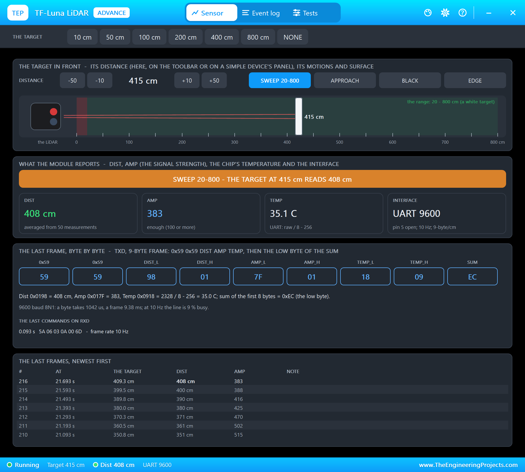
At Run, the Advance module opens its own window, TF-Luna LiDAR, with the look of our TEP Serial Monitor Advance for Proteus. It has three tabs, Sensor, Event log and Tests, plus Settings and Help behind the gear and question mark icons. The status bar at the bottom always shows the target, the reading and the interface.
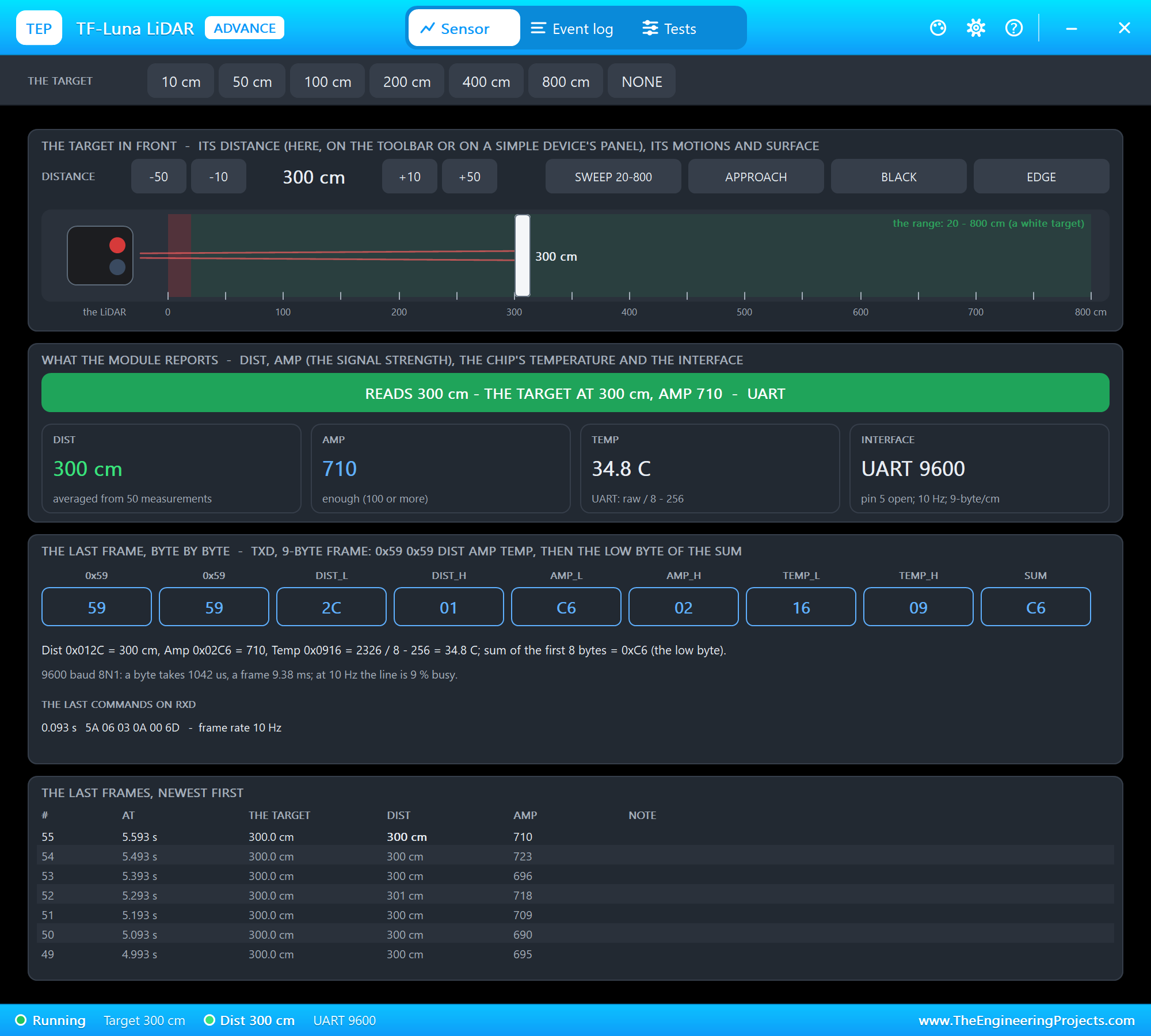
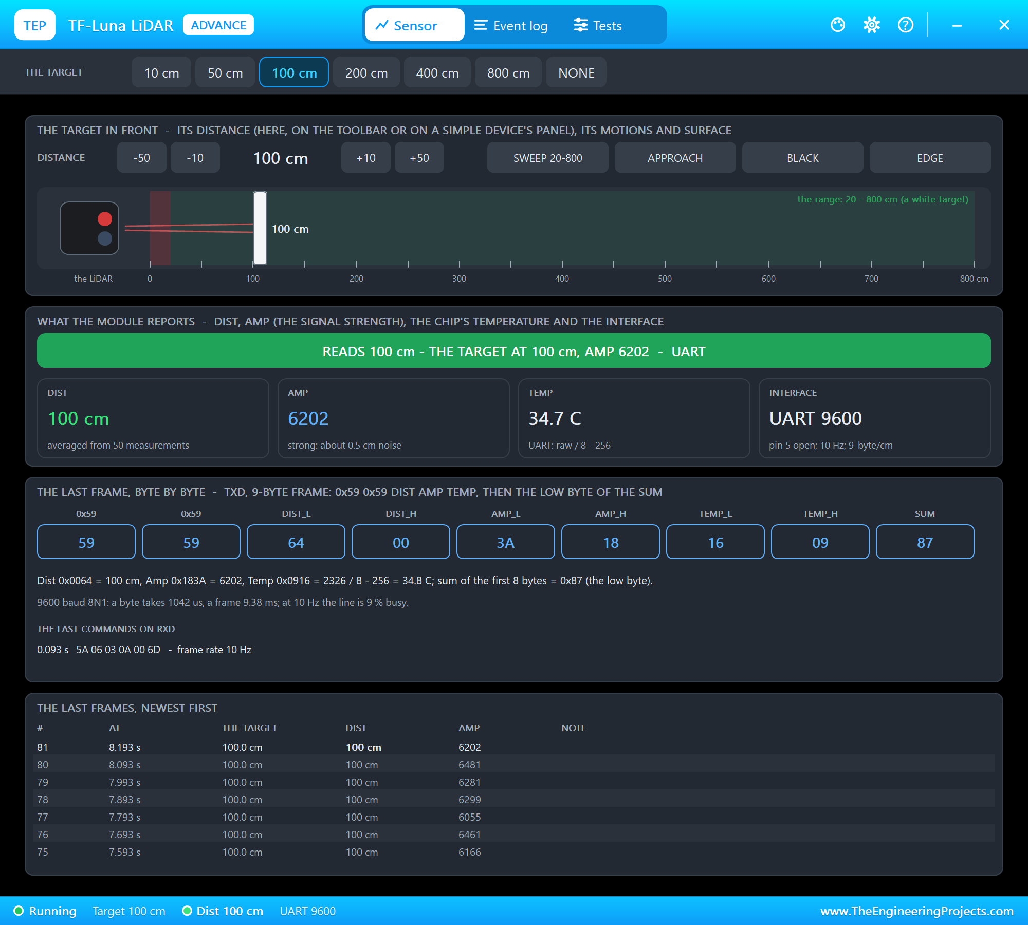
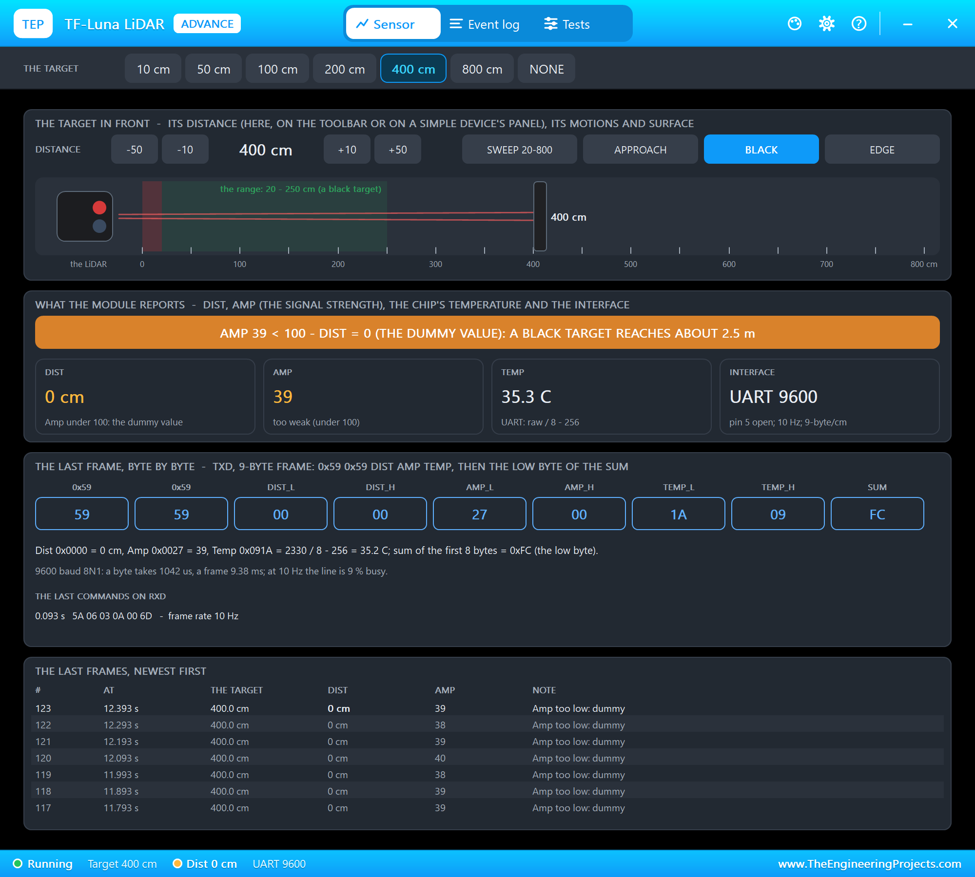
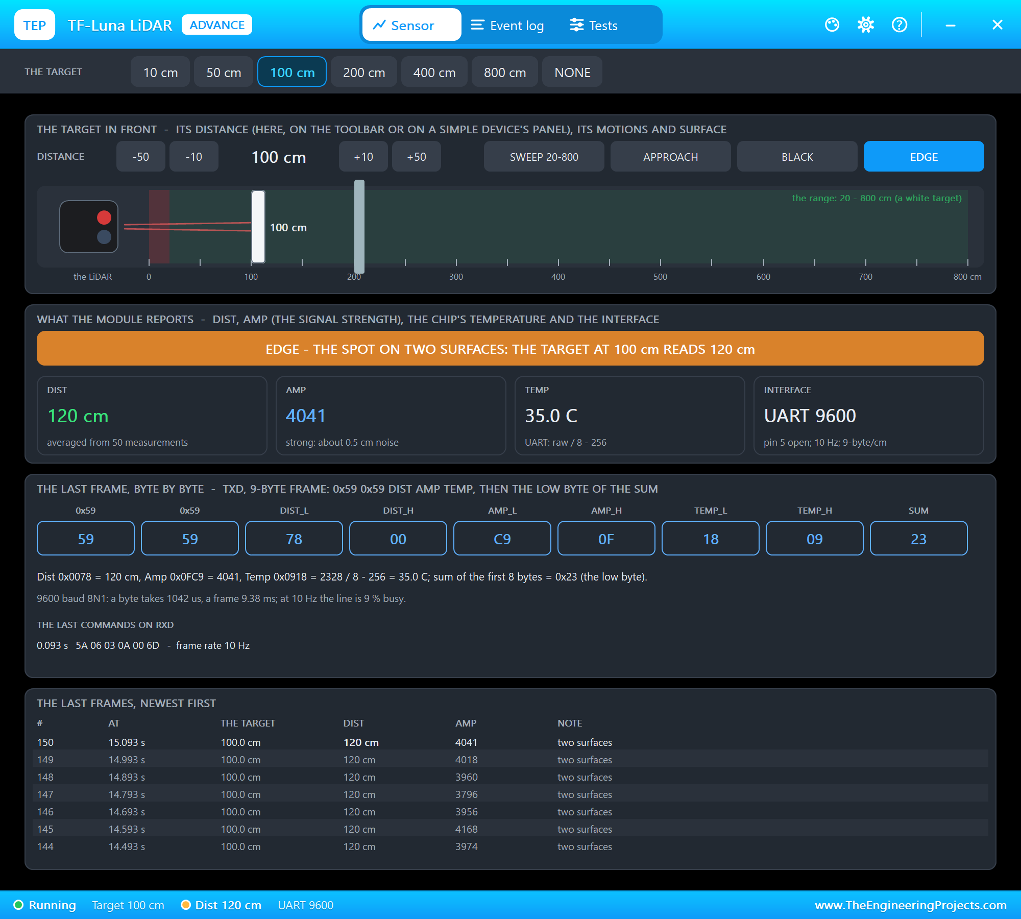
The toolbar carries the presets. The target in front has -50, -10, +10 and +50 cm, the four actions and a side view: the module, its beam, the range shaded green and the dead zone in red. What the module reports shows the banner, Dist, Amp, the temperature and the interface. The last frame, byte by byte takes the nine bytes apart and lists the last commands received - here the sketch's 10 Hz command at 0.093 s; at the bottom are the last frames, newest first, each the average of 50 measurements at 10 Hz. We clicked 100 cm:
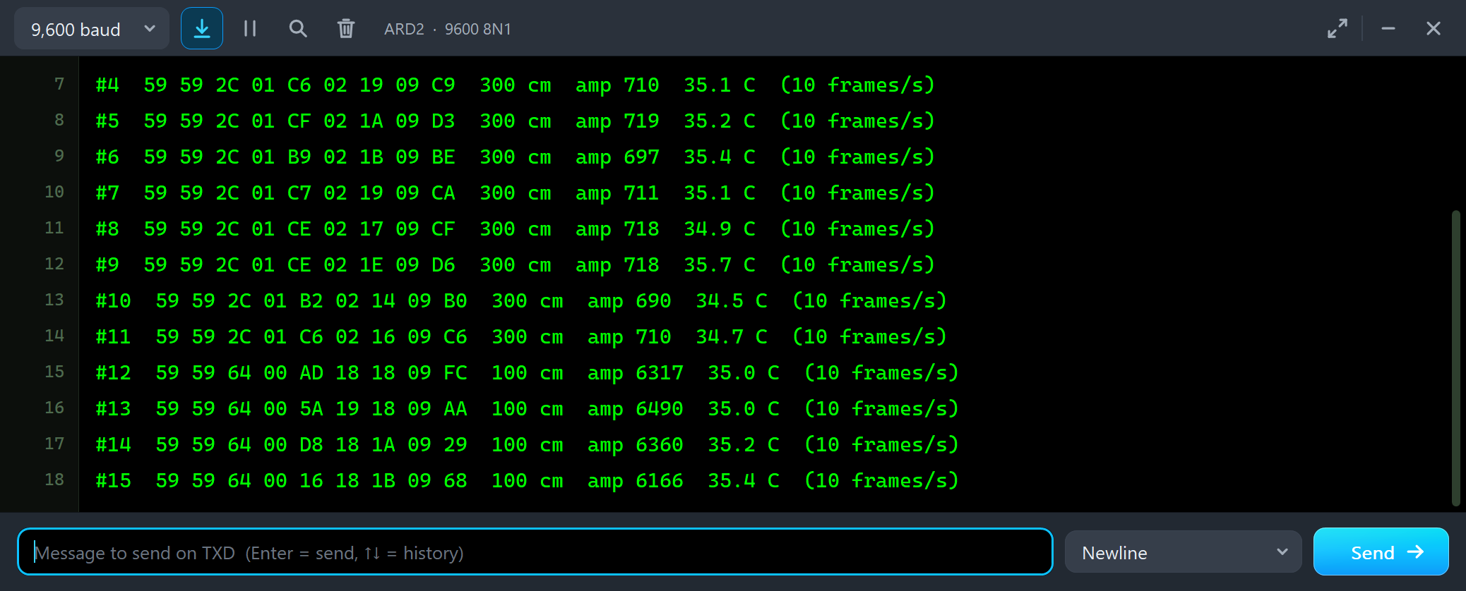
#10  59 59 2C 01 B2 02 14 09 B0  300 cm  amp 690  34.5 C  (10 frames/s)
#11  59 59 2C 01 C6 02 16 09 C6  300 cm  amp 710  34.7 C  (10 frames/s)
#12  59 59 64 00 AD 18 18 09 FC  100 cm  amp 6317  35.0 C  (10 frames/s)
#13  59 59 64 00 5A 19 18 09 AA  100 cm  amp 6490  35.0 C  (10 frames/s)
#14  59 59 64 00 D8 18 1A 09 29  100 cm  amp 6360  35.2 C  (10 frames/s)
From one frame to the next the distance goes from 0x012C to 64 00 = 100 cm, and Amp from about 700 to about 6300 - nine times more for a target three times closer. Then we typed RAW:
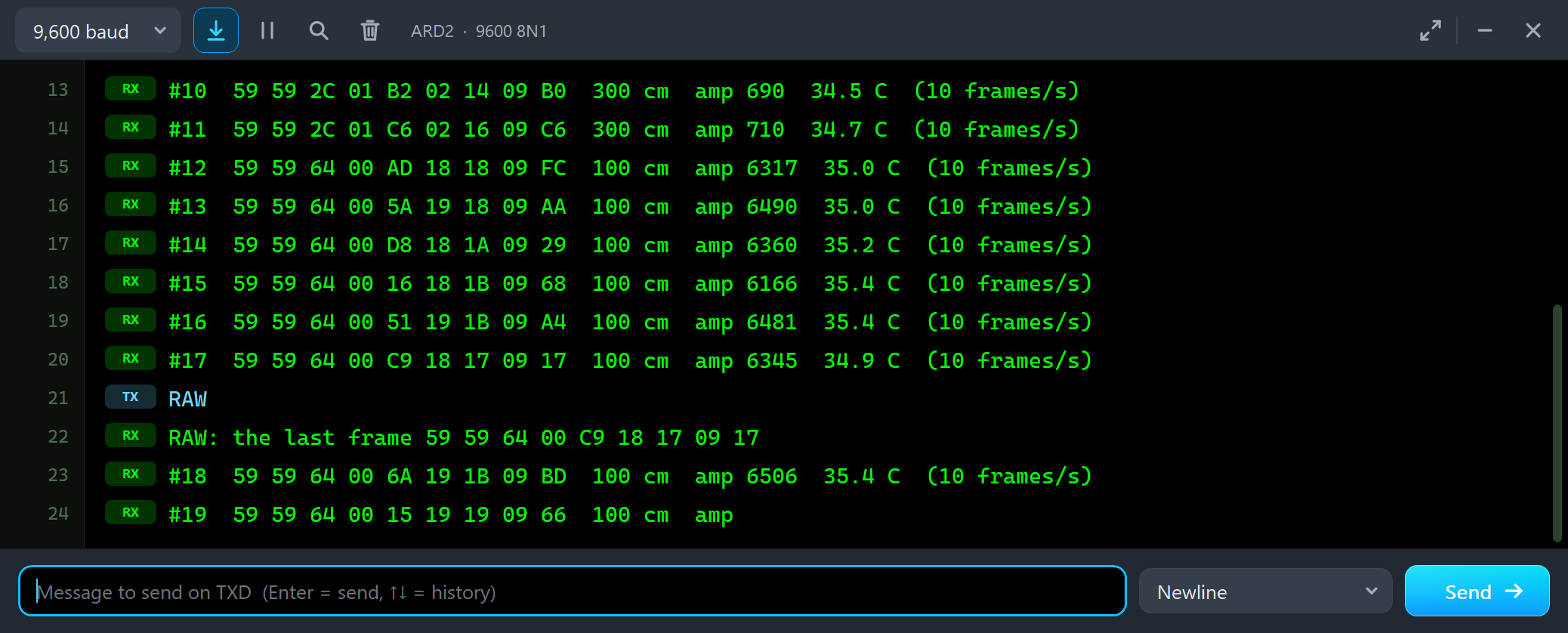
#17  59 59 64 00 C9 18 17 09 17  100 cm  amp 6345  34.9 C  (10 frames/s)
RAW
RAW: the last frame 59 59 64 00 C9 18 17 09 17
#18  59 59 64 00 6A 19 1B 09 BD  100 cm  amp 6506  35.4 C  (10 frames/s)
BLACK at 400 cm: the Dummy Value
Next we clicked BLACK and 400 cm: a black target, which reflects about a tenth of the light, far away:
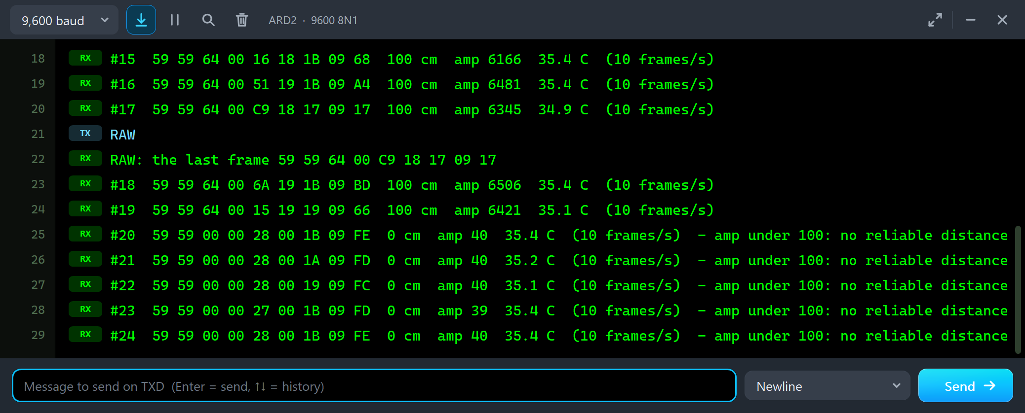
#19  59 59 64 00 15 19 19 09 66  100 cm  amp 6421  35.1 C  (10 frames/s)
#20  59 59 00 00 28 00 1B 09 FE  0 cm  amp 40  35.4 C  (10 frames/s)  - amp under 100: no reliable distance
#21  59 59 00 00 28 00 1A 09 FD  0 cm  amp 40  35.2 C  (10 frames/s)  - amp under 100: no reliable distance
#22  59 59 00 00 28 00 19 09 FC  0 cm  amp 40  35.1 C  (10 frames/s)  - amp under 100: no reliable distance
The frames still come, and their sums still check, but Dist is 0 and Amp is 40. A black target is out of reach beyond about 2.5 m. This is the most common trap with the TF-Luna: a sketch that takes 0 as "something right in front of me" will brake for nothing. Always look at Amp, as the sketch does.
EDGE: a Spot on Two Surfaces
Then BLACK off, 100 cm and EDGE: half of the light spot lands on the target, half on a wall 1 m behind it:
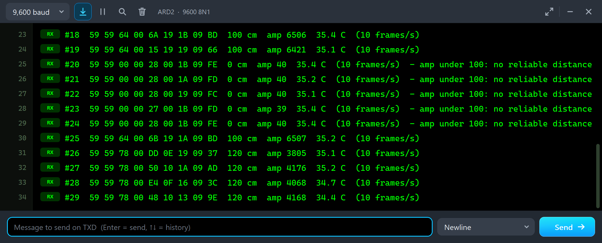
#25  59 59 64 00 6B 19 1A 09 BD  100 cm  amp 6507  35.2 C  (10 frames/s)
#26  59 59 78 00 DD 0E 19 09 37  120 cm  amp 3805  35.1 C  (10 frames/s)
#27  59 59 78 00 50 10 1A 09 AD  120 cm  amp 4176  35.2 C  (10 frames/s)
#28  59 59 78 00 E4 0F 16 09 3C  120 cm  amp 4068  34.7 C  (10 frames/s)
The TF-Luna reports a distance between the two surfaces - here 120 cm, closer to the target because the nearer surface returns more light. Its beam is 2 degrees wide, about 3.5 cm at 1 m and 28 cm at 8 m, so a narrow target or the edge of a table lets the background in. Aim at the middle of the target.
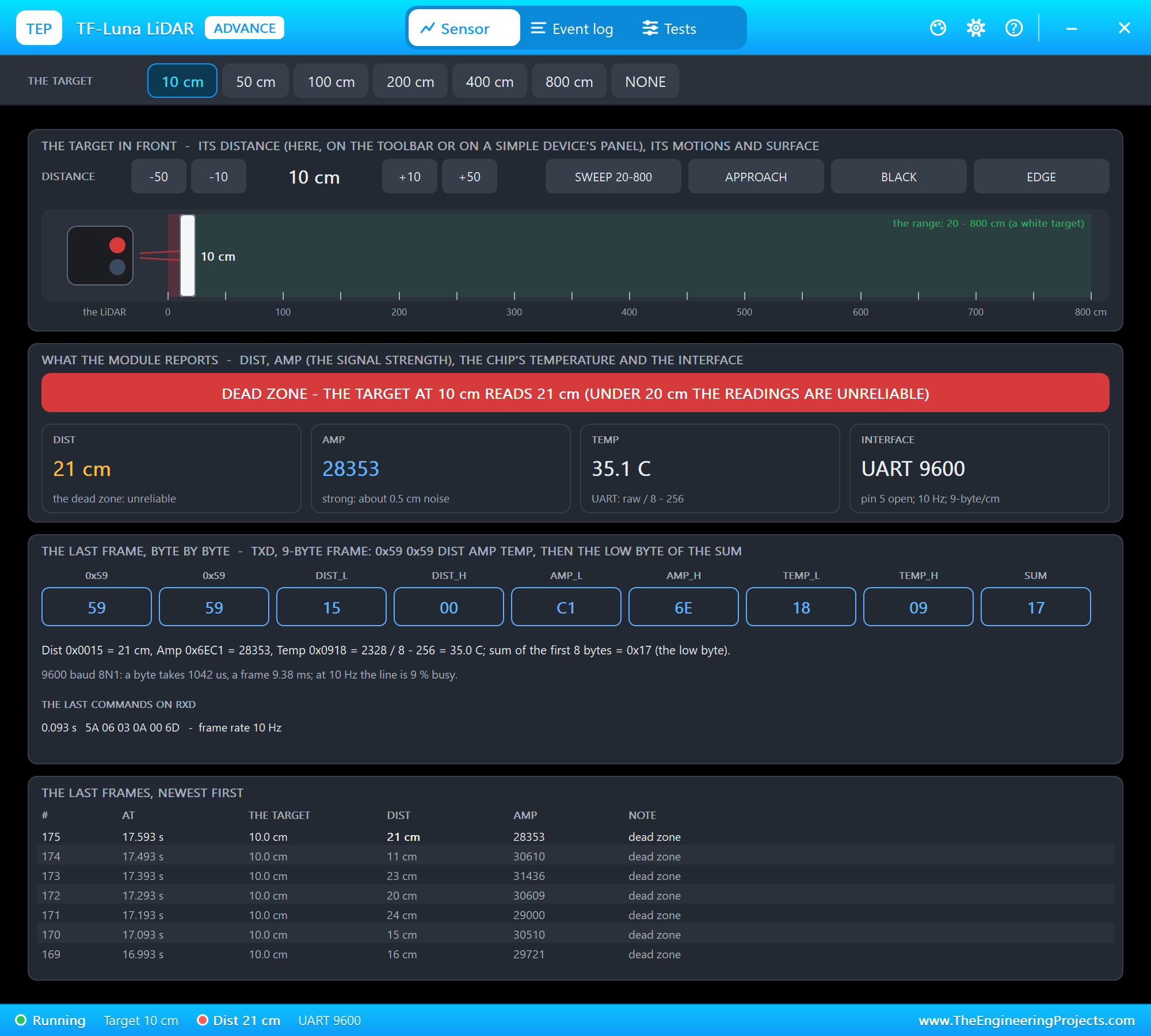
10 cm: the Dead Zone
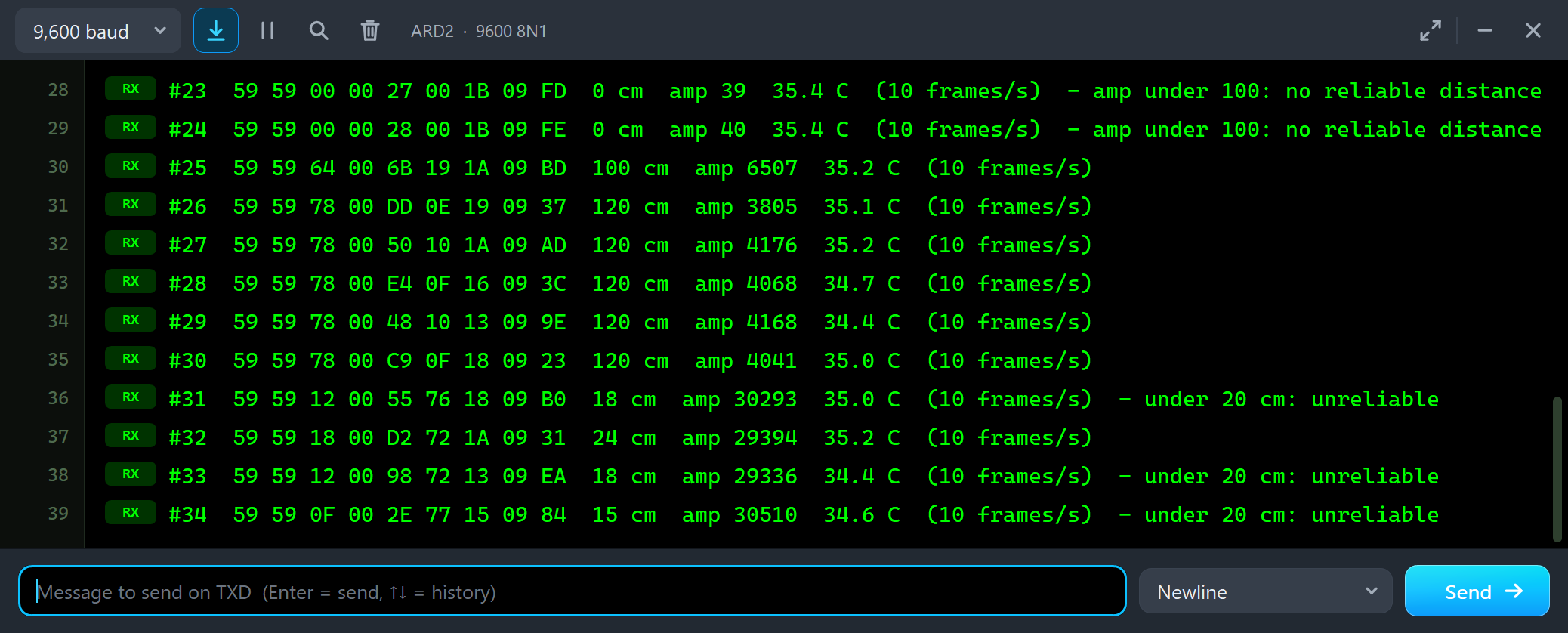
#30  59 59 78 00 C9 0F 18 09 23  120 cm  amp 4041  35.0 C  (10 frames/s)
#31  59 59 12 00 55 76 18 09 B0  18 cm  amp 30293  35.0 C  (10 frames/s)  - under 20 cm: unreliable
#32  59 59 18 00 D2 72 1A 09 31  24 cm  amp 29394  35.2 C  (10 frames/s)
#33  59 59 12 00 98 72 13 09 EA  18 cm  amp 29336  34.4 C  (10 frames/s)  - under 20 cm: unreliable
#34  59 59 0F 00 2E 77 15 09 84  15 cm  amp 30510  34.6 C  (10 frames/s)  - under 20 cm: unreliable
Under 20 cm the manual calls the readings unreliable, and our model shows why: the target at 10 cm reads 15 to 24 cm, a few centimetres too far and jumpy, while Amp is at its top. The sketch marks every reading under 20 cm - but #32 says 24 cm and slips through. Mount the TF-Luna at least 20 cm back from the closest thing it must see.
SWEEP 20-800
SWEEP 20-800 moves the target from 20 to 800 cm and back in 16 seconds:
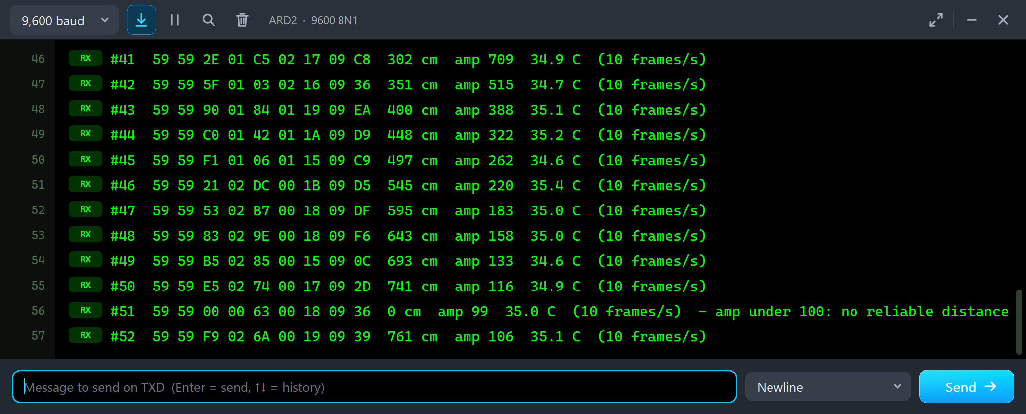
#41  59 59 2E 01 C5 02 17 09 C8  302 cm  amp 709  34.9 C  (10 frames/s)
#42  59 59 5F 01 03 02 16 09 36  351 cm  amp 515  34.7 C  (10 frames/s)
#43  59 59 90 01 84 01 19 09 EA  400 cm  amp 388  35.1 C  (10 frames/s)
#44  59 59 C0 01 42 01 1A 09 D9  448 cm  amp 322  35.2 C  (10 frames/s)
#45  59 59 F1 01 06 01 15 09 C9  497 cm  amp 262  34.6 C  (10 frames/s)
#46  59 59 21 02 DC 00 1B 09 D5  545 cm  amp 220  35.4 C  (10 frames/s)
#47  59 59 53 02 B7 00 18 09 DF  595 cm  amp 183  35.0 C  (10 frames/s)
#48  59 59 83 02 9E 00 18 09 F6  643 cm  amp 158  35.0 C  (10 frames/s)
#49  59 59 B5 02 85 00 15 09 0C  693 cm  amp 133  34.6 C  (10 frames/s)
#50  59 59 E5 02 74 00 17 09 2D  741 cm  amp 116  34.9 C  (10 frames/s)
#51  59 59 00 00 63 00 18 09 36  0 cm  amp 99  35.0 C  (10 frames/s)  - amp under 100: no reliable distance
#52  59 59 F9 02 6A 00 19 09 39  761 cm  amp 106  35.1 C  (10 frames/s)
The target moves about 97 cm a second and the lines are half a second apart. Watch Amp fall with the square of the distance - 709 at 302 cm, 262 at 497 cm, 116 at 741 cm. At about 750 cm a single frame has Amp 99 and Dist 0, and the next one 761 cm with Amp 106: near the end of the range the signal hovers around the threshold, and readings of 0 appear in between.
TRIG and CONT
At the end of the sweep we typed TRIG three times:
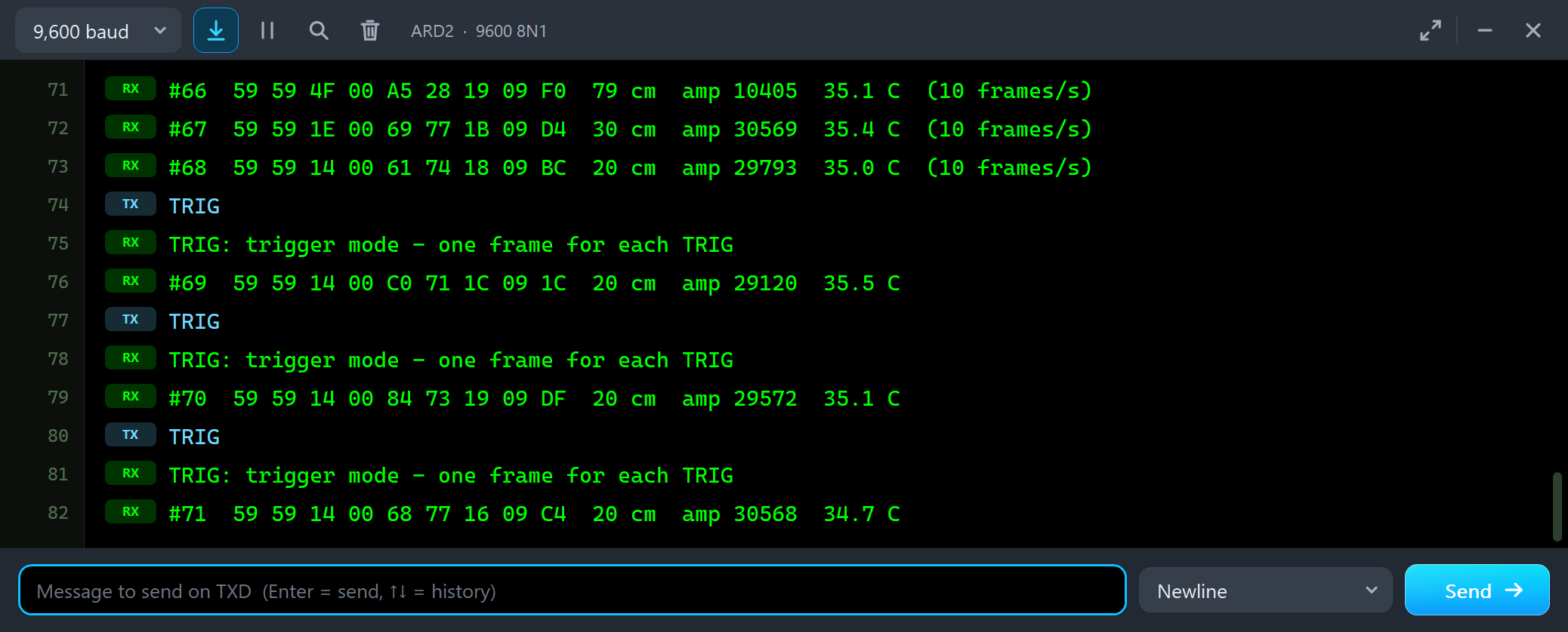
#67  59 59 1E 00 69 77 1B 09 D4  30 cm  amp 30569  35.4 C  (10 frames/s)
#68  59 59 14 00 61 74 18 09 BC  20 cm  amp 29793  35.0 C  (10 frames/s)
TRIG
TRIG: trigger mode - one frame for each TRIG
#69  59 59 14 00 C0 71 1C 09 1C  20 cm  amp 29120  35.5 C
TRIG
TRIG: trigger mode - one frame for each TRIG
#70  59 59 14 00 84 73 19 09 DF  20 cm  amp 29572  35.1 C
The first TRIG sets the frame rate to 0 - trigger mode - and sends the trigger command 5A 04 04 62; each later TRIG sends one more. Each brings exactly one frame, and the sketch prints it without a rate. CONT sets 10 Hz again.
The Test Tools
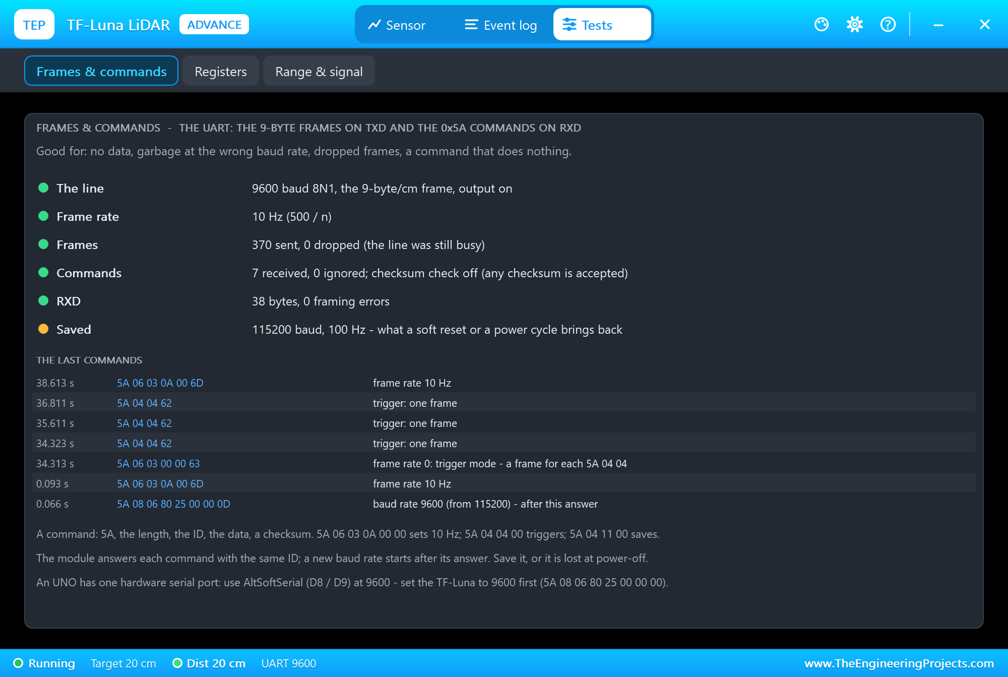
The Frames & commands tool is the one to open when no data comes, or garbage. It shows the line - 9600 baud 8N1, the 9-byte/cm frame - the frame rate, the frames sent and dropped, the commands received and ignored, the bytes and framing errors on RXD, and what is saved: still 115200 baud and 100 Hz, in amber, because the sketch never sends the save command. Below are the last commands with their bytes: the baud rate change, 10 Hz, trigger mode, the triggers and 10 Hz again.
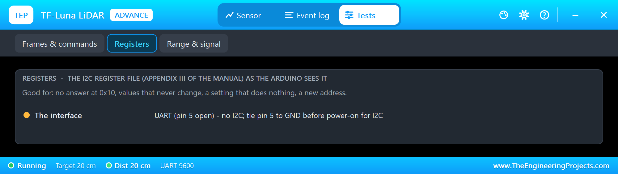
The Registers tool is for I2C: the address that answers, the mode, pin 6, the reads and writes, and the registers as the Arduino sees them. U2 talks UART, so the tool explains that pin 5 must be at GND before power-on.
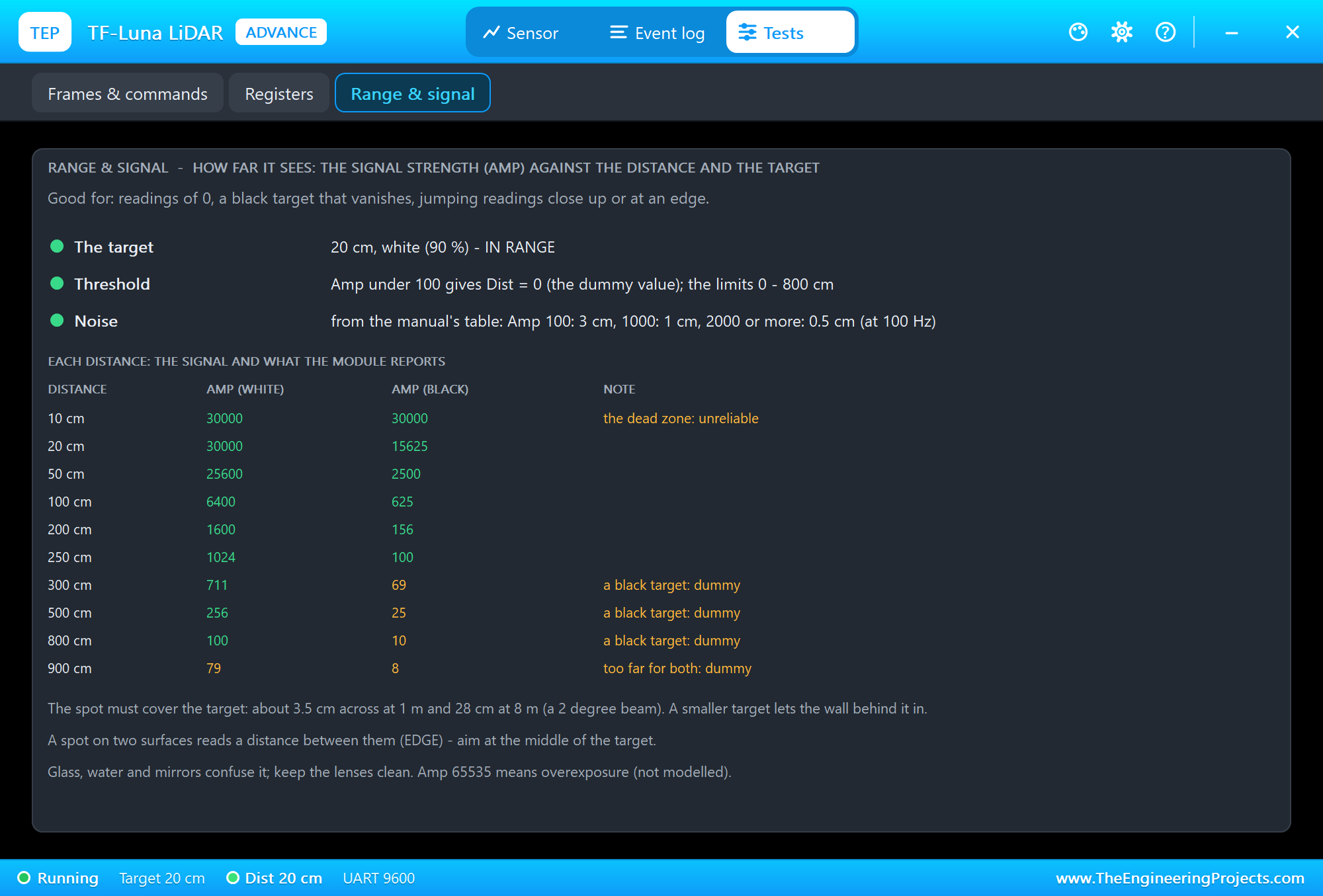
The Range & signal tool answers "why do I get 0?". It lists Amp for a white and a black target from 10 to 900 cm: a white target keeps Amp at 100 or more out to 800 cm, a black one only to 250 cm, and 10 cm is in the dead zone.
The Event Log
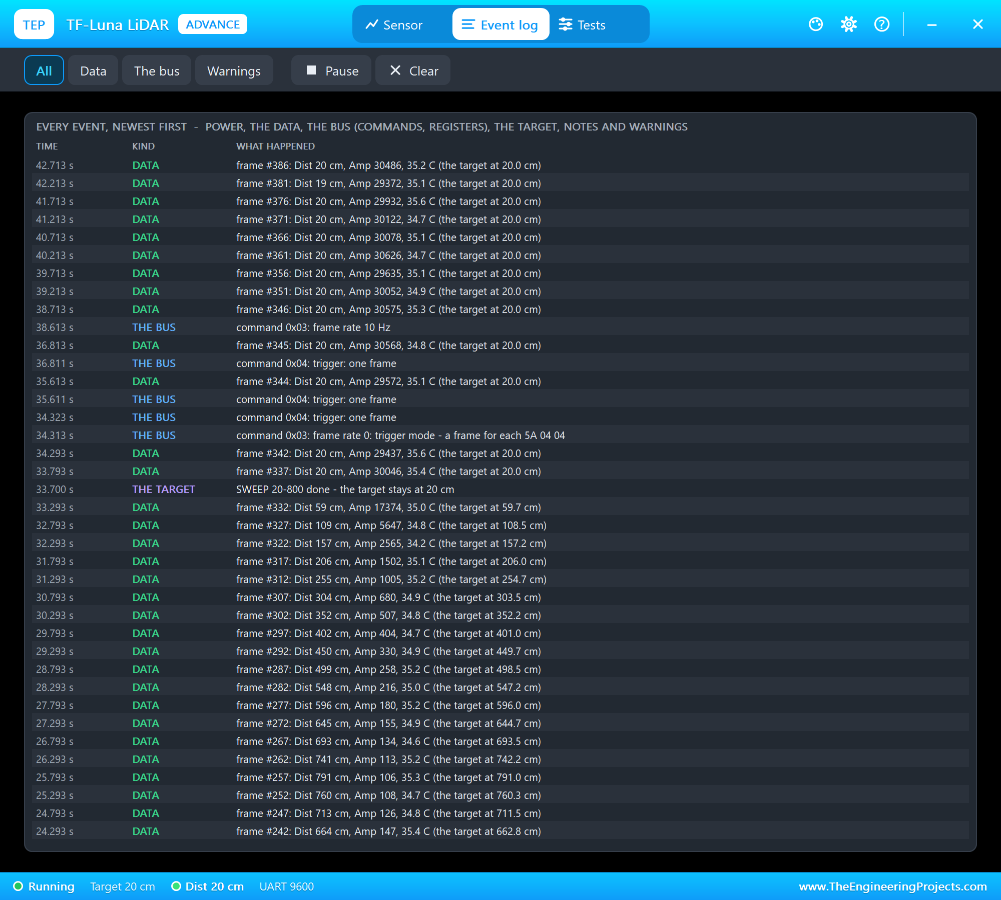
The Event log lists everything that happened, newest first: power, the data (one frame in five here), the bus - commands and register writes - the target and its actions, notes and warnings. Filter it by data, the bus or warnings, pause it, or clear it.
Move the Target on the STATUS Panel
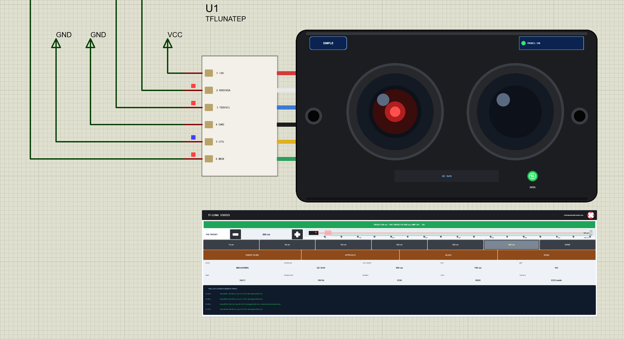
Now let's go back to node 1, the I2C node. We clicked the buttons of U1's STATUS panel with the mouse while the simulation ran. First 800 cm:
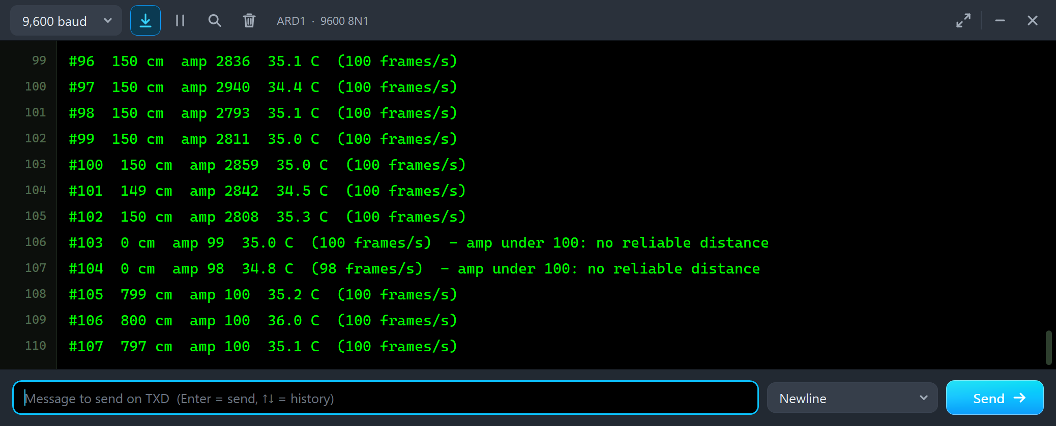
#101  149 cm  amp 2842  34.5 C  (100 frames/s)
#102  150 cm  amp 2808  35.3 C  (100 frames/s)
#103  0 cm  amp 99  35.0 C  (100 frames/s)  - amp under 100: no reliable distance
#104  0 cm  amp 98  34.8 C  (98 frames/s)  - amp under 100: no reliable distance
#105  799 cm  amp 100  35.2 C  (100 frames/s)
#106  800 cm  amp 100  36.0 C  (100 frames/s)
#107  797 cm  amp 100  35.1 C  (100 frames/s)
At 8 m a white target gives Amp right at 100. The readings say 797 to 800 cm, but two of them - with Amp 99 and 98 - are 0. That is the edge of the range: the same signal, a hair weaker, and the module gives up. Then NONE:
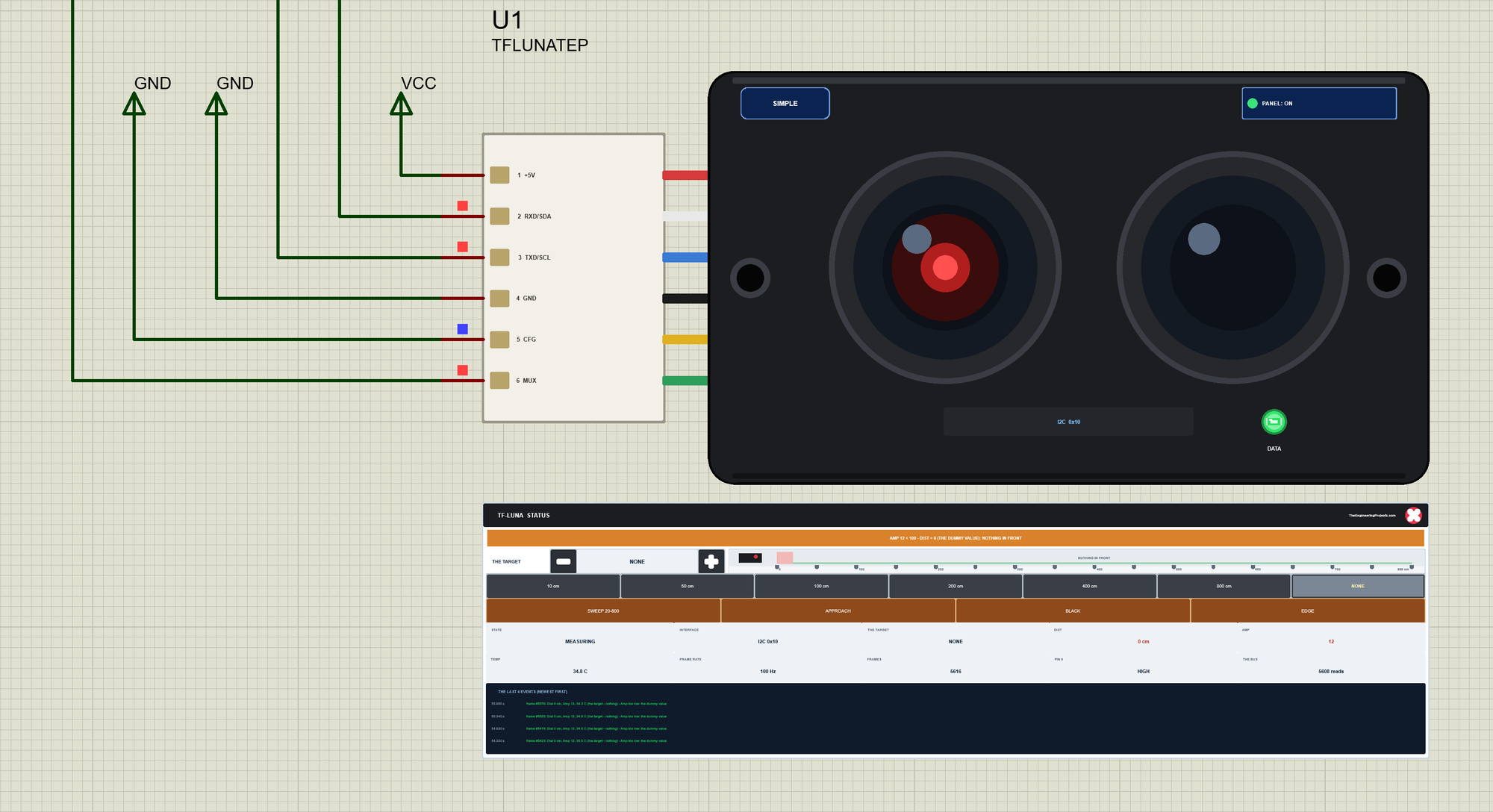
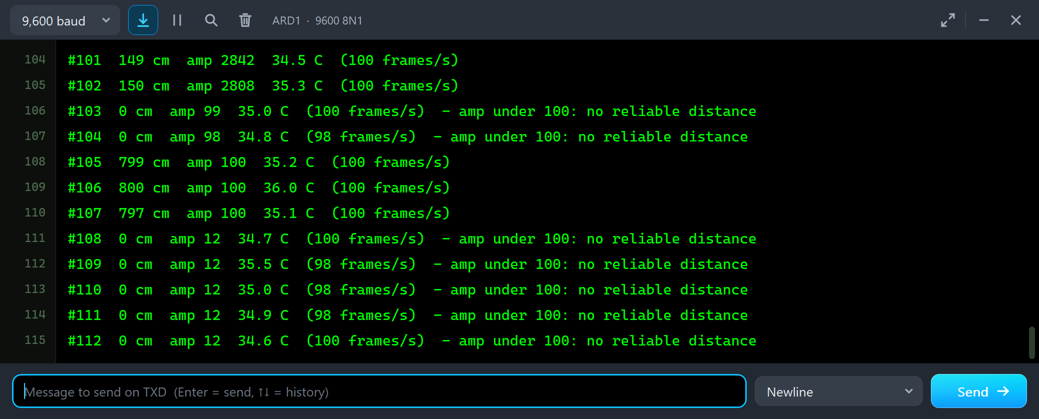
#107  797 cm  amp 100  35.1 C  (100 frames/s)
#108  0 cm  amp 12  34.7 C  (100 frames/s)  - amp under 100: no reliable distance
#109  0 cm  amp 12  35.5 C  (98 frames/s)  - amp under 100: no reliable distance
#110  0 cm  amp 12  35.0 C  (98 frames/s)  - amp under 100: no reliable distance
APPROACH: into the Dead Zone
APPROACH brings the target from 300 cm to 5 cm in 10 seconds, slower as it comes close:
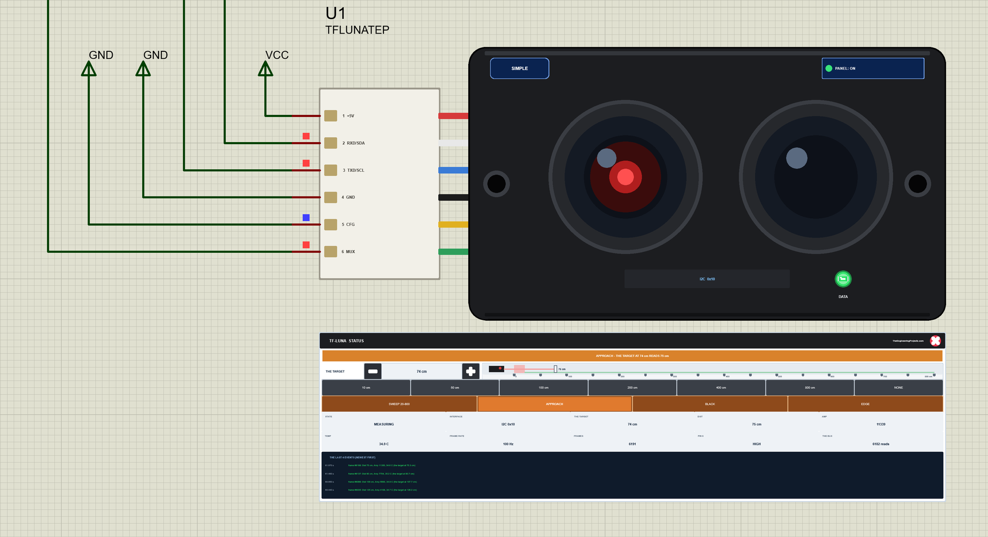
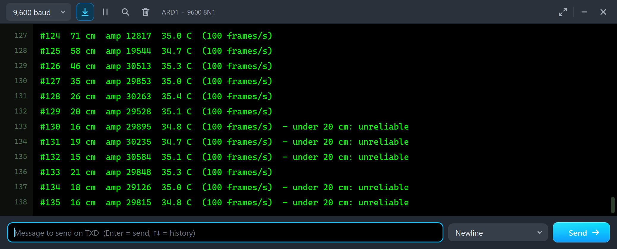
#124  71 cm  amp 12817  35.0 C  (100 frames/s)
#125  58 cm  amp 19544  34.7 C  (100 frames/s)
#126  46 cm  amp 30513  35.3 C  (100 frames/s)
#127  35 cm  amp 29853  35.0 C  (100 frames/s)
#128  26 cm  amp 30263  35.4 C  (100 frames/s)
#129  20 cm  amp 29528  35.1 C  (100 frames/s)
#130  16 cm  amp 29895  34.8 C  (100 frames/s)  - under 20 cm: unreliable
#131  19 cm  amp 30235  34.7 C  (100 frames/s)  - under 20 cm: unreliable
#132  15 cm  amp 30584  35.1 C  (100 frames/s)  - under 20 cm: unreliable
#133  21 cm  amp 29848  35.3 C  (100 frames/s)
The readings follow the target down to 20 cm. Then the target goes on to 5 cm, but the readings stay between 15 and 21 cm: in the dead zone the TF-Luna cannot tell 15 cm from 5 cm. Notice Amp too: from about 46 cm it stays near 30,000, the model's top value (a real TF-Luna dazzled by a mirror reports 65535 - overexposure, not modelled). A robot that must stop before a wall should stop at 30 cm, not at 5.
FPS 250 and RAW
We clicked 50 cm and typed FPS 250, then RAW:
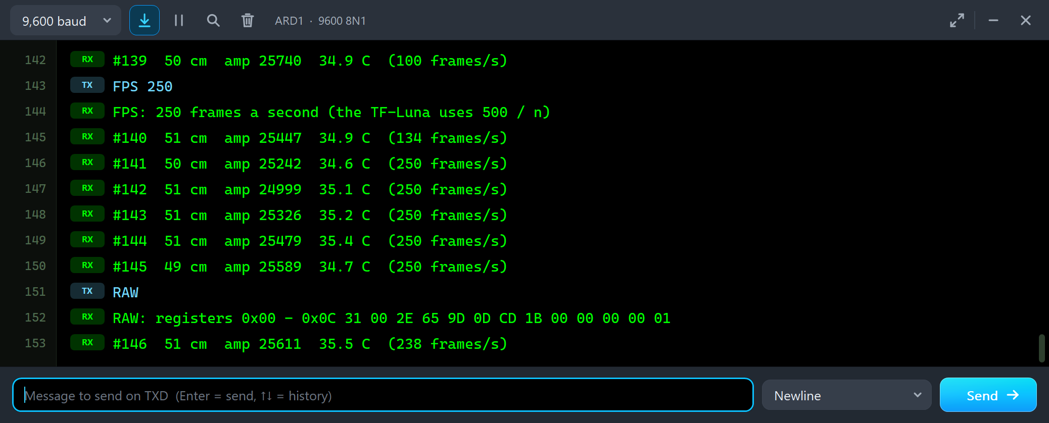
#139  50 cm  amp 25740  34.9 C  (100 frames/s)
FPS 250
FPS: 250 frames a second (the TF-Luna uses 500 / n)
#140  51 cm  amp 25447  34.9 C  (134 frames/s)
#141  50 cm  amp 25242  34.6 C  (250 frames/s)
#142  51 cm  amp 24999  35.1 C  (250 frames/s)
#145  49 cm  amp 25589  34.7 C  (250 frames/s)
RAW
RAW: registers 0x00 - 0x0C 31 00 2E 65 9D 0D CD 1B 00 00 00 00 01
#146  51 cm  amp 25611  35.5 C  (238 frames/s)
FPS 250 writes 250 to the FPS register, and the sketch now counts 250 frames a second - every one of them read over I2C, one per rising edge of pin 6. RAW reads the first 13 registers: 31 00 is 49 cm, 2E 65 is Amp 25902, 9D 0D is 3485 hundredths of a degree, 34.85 C, then the tick counter, two empty bytes and the version, 0.0.1 read backwards: 1.0.0, our model's own version. The line after RAW counts only 238 frames: while the sketch was busy printing, a few measurements came and went unread.
TRIG over I2C
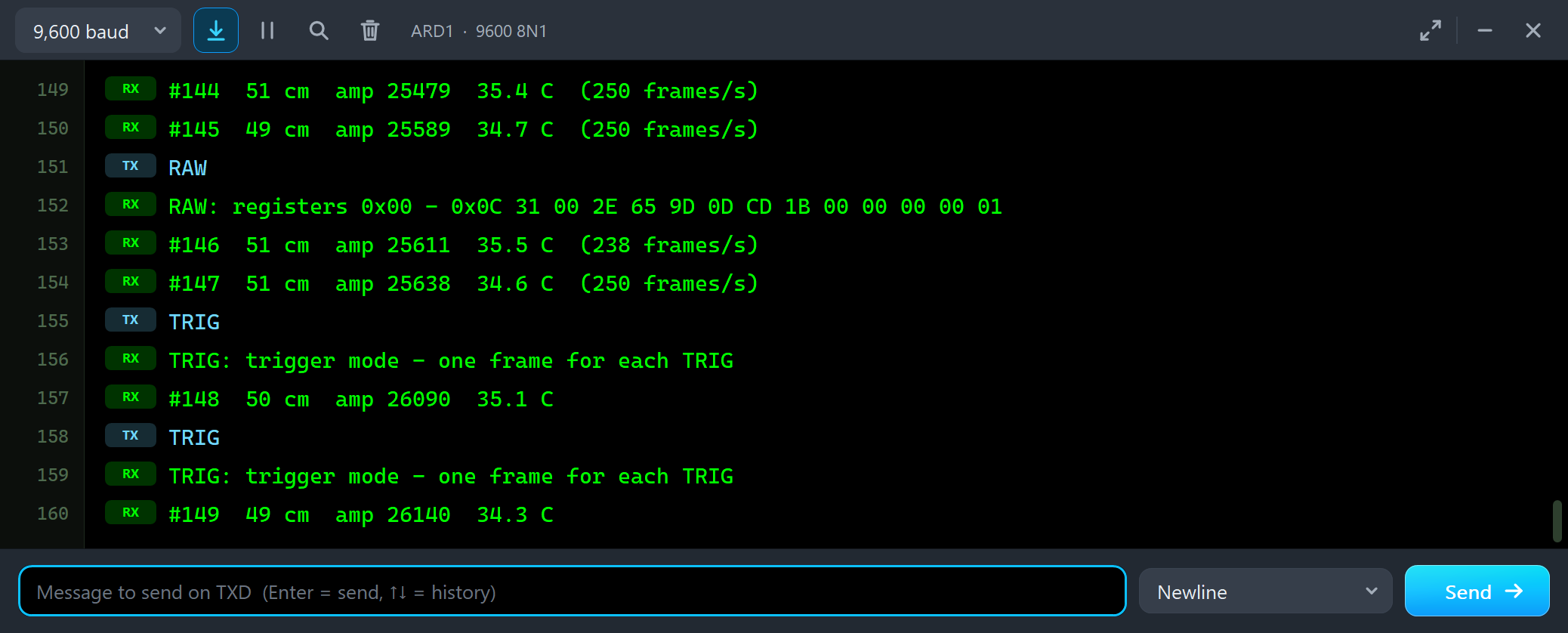
#147  51 cm  amp 25638  34.6 C  (250 frames/s)
TRIG
TRIG: trigger mode - one frame for each TRIG
#148  50 cm  amp 26090  35.1 C
TRIG
TRIG: trigger mode - one frame for each TRIG
#149  49 cm  amp 26140  34.3 C
Over I2C, trigger mode is register 0x23 = 1 and each trigger is 0x24 = 1. Pin 6 rises once for each, and the sketch reads one frame. Then CONT sets 100 Hz again.
The Simulation Log
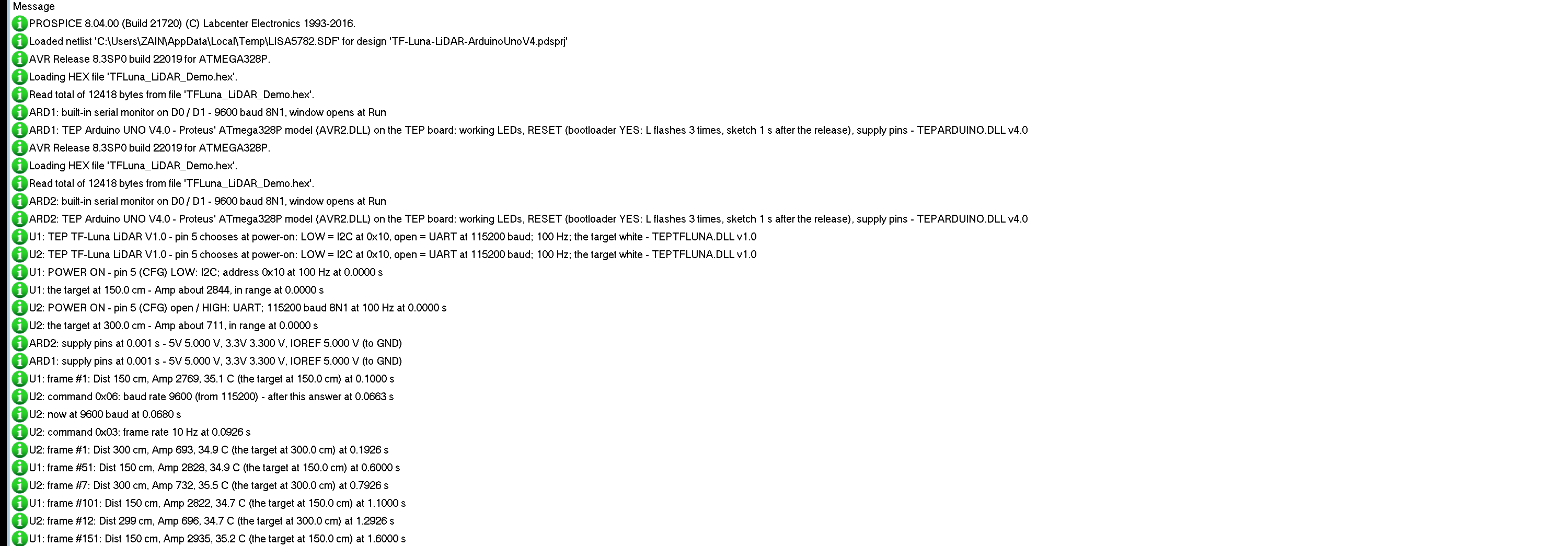
The modules also write to the simulation log of Proteus, with the exact simulation time. This part shows the start:
U1: POWER ON - pin 5 (CFG) LOW: I2C; address 0x10 at 100 Hz at 0.0000 s
U1: the target at 150.0 cm - Amp about 2844, in range at 0.0000 s
U2: POWER ON - pin 5 (CFG) open / HIGH: UART; 115200 baud 8N1 at 100 Hz at 0.0000 s
U2: the target at 300.0 cm - Amp about 711, in range at 0.0000 s
U1: frame #1: Dist 150 cm, Amp 2769, 35.1 C (the target at 150.0 cm) at 0.1000 s
U2: command 0x06: baud rate 9600 (from 115200) - after this answer at 0.0663 s
U2: now at 9600 baud at 0.0680 s
U2: command 0x03: frame rate 10 Hz at 0.0926 s
U2: frame #1: Dist 300 cm, Amp 693, 34.9 C (the target at 300.0 cm) at 0.1926 s
Both modules power on at 0 s and read pin 5: U1 chooses I2C, U2 the UART. U1 has its first frame 100 ms later. U2 gets the baud rate command at 0.0663 s, answers it at 115200, and is at 9600 from 0.0680 s; the frame rate command follows, and the first 10 Hz frame comes 100 ms after it. The log gets one frame of each module every half second; the Event log has more.
How the Model Works
The module is a digital model. VCC and GND power it, and pin 5 is read at power-on. In UART mode the model decodes the bytes on RXD bit by bit and sends each frame on TXD with every bit at its exact time. In I2C mode it is an I2C slave that only ever pulls SDA LOW, as an open-drain device should, and it drives pin 6. Inside, it makes 500 measurements a second from the target's distance, the target's colour and the manual's noise, and averages them into frames. Proteus calls the model only at the edges that matter and at the frames, so it costs little time.
Troubleshooting
- "no answer at 0x10" or "no data yet": pin 5 was not at GND at power-on (the label on the module says UART), SDA and SCL swapped, or no power. Without pin 6 on D2 the sketch never reads.
- "no frame yet": TXD and RXD swapped, pin 5 at GND, or the module is not at 9600 - the Frames & commands tool counts the framing errors on RXD.
- Dist 0: Amp under 100 - nothing there, too far, or a black target beyond about 2.5 m.
- Jumpy readings under 20 cm: the dead zone. A value between two distances: the spot is on an edge.
- No part or no monitor: TEPTFLUNA.DLL or TEPARDUINO.DLL is missing from MODELS and the project folder; a closed monitor opens again with a click on the UNO's USB port.
Things to Know Before Using a Real TF-Luna
- Power: 3.7 to 5.2 V, about 70 mA with peaks of 150 mA, and no protection against reversed or too high a voltage - check the wires first.
- Levels: the signals are 3.3 V. Its TXD is a valid HIGH for a 5 V UNO, but use a level shifter for the UNO's TX into RXD, or pull SDA and SCL up to 3.3 V only.
- Pin 5 is read at power-on: change it, then power the module again.
- Save or lose: commands act at once but are forgotten at power-off unless you send the save command.
- Light and surfaces: glass, water, mirrors and strong sunlight confuse it; keep the lenses clean. For a robot, compare it with our Sharp IR Distance Sensor Library for Proteus and JSN-SR04T Waterproof Ultrasonic Sensor Library for Proteus; for wider fields of view, see multi-zone FlightSense distance sensors.
Limitations of the Simulation
- Not modelled: the infrared light itself, the target's size against the spot, glass, water, mirrors, sunlight and overexposure (Amp 65535), the supply voltage and current, the 3.3 V signal level, the low-power modes, pin 6's on / off output in UART mode and the start-up time beyond the first frame after 100 ms. The signal strength's curve, the dead-zone readings and the 1 ms answer time are the model's values.
- The LED, the badge, the label, the panel button and the panels are TEP additions.
- The model is our own, written from Benewake's product manual. TF-Luna and Benewake are names of Benewake (Beijing) Co. Ltd. This library is not made or endorsed by Benewake or by Labcenter.
- Licences: the demo sketch uses AltSoftSerial 1.4 by Paul Stoffregen (MIT License); it is not in the package, and its licence text is in the README. The HEX file also contains the Arduino AVR core 1.8.6 with Wire and LGPL-licensed code; the licence note and the source link are in the README.
- Tested in Proteus 8.5 in October 2026 (the demo as shipped on two Arduino UNO V4.0 boards with their built-in monitors: 100 cm, RAW, BLACK at 400 cm, EDGE, 10 cm, SWEEP 20-800, TRIG and the three tools on node 2 in UART; 800 cm, NONE, APPROACH, FPS 250, RAW and TRIG on node 1 in I2C with the mouse, the red X and PANEL; 89.8 s of simulation took 202 s, about 0.44 x real time with the pop-up and both monitors open). Proteus 7 is not supported.
So, that was all about the TF-Luna LiDAR Distance Sensor Library for Proteus V1.0. I hope the two interfaces, the frames, the registers and the meaning of Amp are clear now, and that your robot or level meter works from the first run. If you use the TF-Luna LiDAR Sensor Library for Proteus in a project, please share it in the comments or in our forum, and if you have any questions, ask in the comments and I will help you out. Till the next tutorial, take care and have fun!
Comments
0