


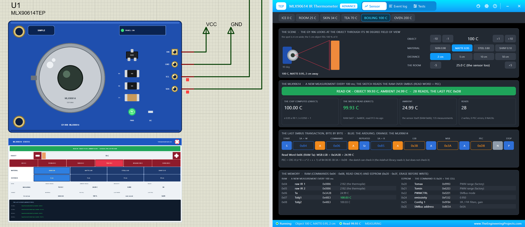
MLX90614 IR Thermometer Library for Proteus V1.0: GY-906 Non-Contact


Hello friends, I hope you all are doing great. Today, I am going to share the new MLX90614 IR Thermometer Library for Proteus V1.0. The MLX90614 is the sensor inside many non-contact thermometers: point it at a forehead, a cup of tea, a motor or a soldering iron, and it tells you the temperature without touching it. On the blue GY-906 module it is one of the most popular sensors for Arduino projects, and now you can build and test those projects in Proteus.
Behind the part sits our own model, not a part that shows a number. The MLX90614 answers the Arduino on the SMBus exactly as the datasheet says: Read Word with a repeated start, Write Word, and a PEC checksum on every word. It measures every 100 ms, keeps its emissivity in its EEPROM, and works out the object's temperature from the infra-red it sees, so a shiny object reads low and a far one reads like the room, just as on your desk. You get two devices: the GY-906 as a Simple device with a live STATUS panel and as an Advance device with a pop-up window and three test tools. The demo runs the Adafruit MLX90614 Library on our Arduino UNO V4.0.
NOTICE: an IR thermometer is easy to fake: read a temperature from a property and hand it to the Arduino. We wanted more. Our MLX90614 answers the SMBus bit by bit with the real PEC, stores the emissivity in its EEPROM and sees the object through its field of view, so the Adafruit library reads it exactly as on your desk, and the classic mistakes fail exactly as they do there. It took our team a lot of hard work. Your feedback is the fuel that keeps us going, so please tell us what you think in the comments below or in the MLX90614 board of our forum. And if our free libraries help you, you can buy us a coffee. So, let's get started with the MLX90614 IR Thermometer Library for Proteus V1.0:
What is the MLX90614?
The MLX90614 from Melexis is an infra-red thermometer in a small TO-39 metal can. Behind the window on top sit a thermopile, which turns the infra-red falling on it into a tiny voltage, and a sensor for the temperature of the chip itself. A built-in processor turns both into two temperatures: the object the sensor looks at and the ambient, the sensor itself. The GY-906 module adds a 3.3 V regulator, two 10 kohm pull-up resistors and a four-pin header: VIN, GND, SCL and SDA. For temperature sensors in general, read our What are Temperature Sensors?
| MLX90614 (GY-906, the BAA version) | |
|---|---|
| Object temperature | -70 to 382.19 C, 0.02 C a step |
| Ambient temperature | -40 to 125 C (the sensor itself) |
| Field of view | 90 degrees |
| Measurements | a new one every 100 ms, the first 250 ms after power-up |
| Emissivity | in the EEPROM, 0.1 to 1.0, factory 1.000 |
| Interface | SMBus (I2C) at address 0x5A, 10 to 100 kHz, with a PEC on every word |
| Supply | VIN 3.3 to 5 V on the GY-906 (the chip runs at 3.3 V) |
| Devices | MLX90614TEP (Simple), MLX90614ADVTEP (Advance) |
How an IR Thermometer Works
Every object sends out infra-red, and the hotter it is, the more: the power grows with the fourth power of its absolute temperature. The MLX90614 does not measure the object's temperature directly; it measures the difference between the infra-red coming from the object and what the sensor itself sends back, and works out the temperature that would give that difference. That is why it needs its own temperature, the ambient, too.
Emissivity
A perfect black object sends out all the infra-red its temperature allows; real surfaces send less. That fraction is the emissivity: about 0.98 for skin, 0.95 for a matte or painted surface, 0.8 for oxidised steel and only about 0.1 for shiny metal. The MLX90614 keeps one emissivity in its EEPROM, 1.000 from the factory, and assumes the object has it. When the object's real emissivity is lower, the sensor sees less infra-red than it expects, and the reading is too close to the room's temperature. In kelvin: To^4 = Ta^4 + (e_object / e_EEPROM) x (T^4 - Ta^4).
The Field of View
The GY-906 uses the BAA version with a 90 degree field of view: the sensor sees a spot about twice as wide as the distance. At 2 cm the spot is 4 cm wide, at 50 cm it is a metre. When the object is smaller than the spot, the rest of the spot is the room, and the reading moves towards the room's temperature. The model gives the object a width of 5 cm, so it fills the spot up to 2.5 cm away.
The SMBus and the PEC
The MLX90614 talks SMBus, a stricter version of I2C. A Read Word is: START, the address 0x5A with the write bit (0xB4), the command, then a repeated START without a STOP, the address with the read bit (0xB5), and three bytes from the sensor: the low byte, the high byte and the PEC. The PEC is a CRC-8 (x^8 + x^2 + x + 1) over all the bytes before it, so the Arduino can check that nothing was garbled. Commands 0x00 to 0x1F read the RAM (0x06 is the ambient, 0x07 the object), commands 0x20 to 0x3F the EEPROM (0x24 is the emissivity). A temperature word is kelvin x 50, so 0x3A3B = 14907 x 0.02 - 273.15 = 24.99 C.
What's New in MLX90614 IR Thermometer Library for Proteus V1.0
- A real part: the blue GY-906 module drawn at about three times its real size, with the MLX90614 can and its IR window, the regulator, the pull-ups and the header VIN, GND, SCL and SDA.
- Two styles: a Simple device with a STATUS panel and an Advance device with a pop-up window; the LEDs and the panel button sit on the board itself.
- The real SMBus: Read Word with the repeated start, Write Word, the PEC both ways, NACKs where the datasheet asks for them.
- The real memory: the RAM with Ta, Tobj1 and Tobj2, and the EEPROM with the emissivity, erase before write, 5 ms a cell.
- The physics: the object's temperature from its infra-red, its emissivity and the 90 degree field of view.
- Scene controls: the object from ICE 0 C to OVEN 200 C, four materials and four distances, on the STATUS panel or in the pop-up; the room's temperature in the pop-up.
- Mistake detection: a read without the repeated start, a read before the first measurement, a wrong PEC, an EEPROM write without the erase, an access during an EEPROM write.
- Three test tools on the Advance device: SMBus, Readings and Emissivity and FOV.
- A two-node demo on our Arduino UNO V4.0 with the Adafruit library: skin on node 1 and a cup of tea on node 2.
- A compact package: about 1.29 MB, without the C++ source code of the model.
The GY-906 Module
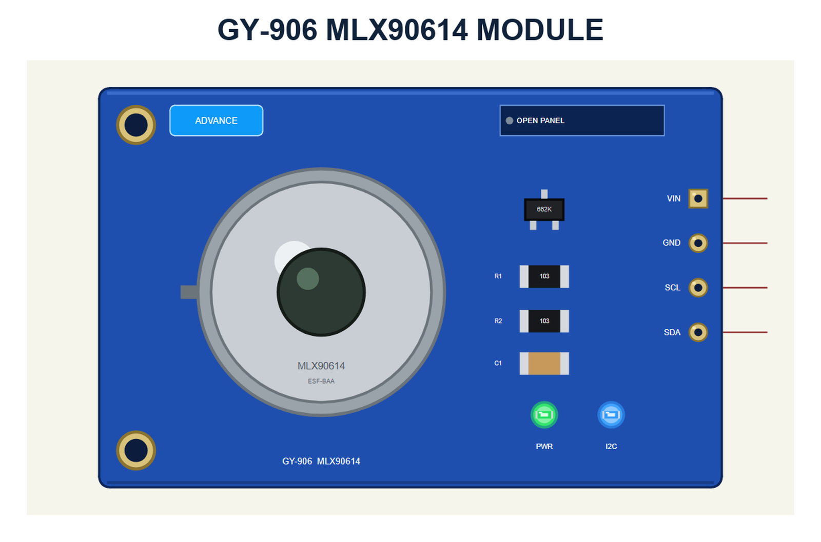
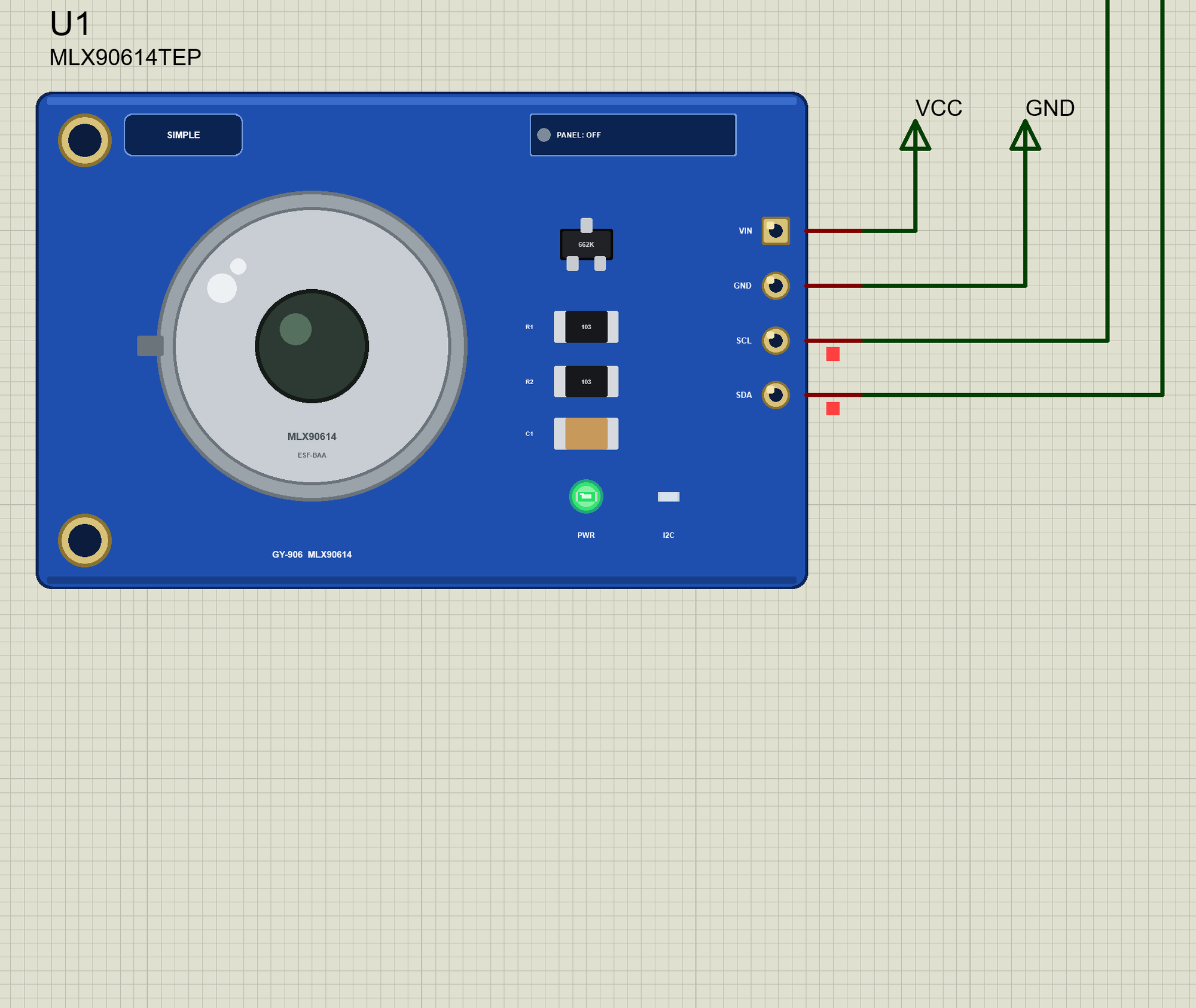
The part looks like the one in your kit: the blue board with the MLX90614 in its silver TO-39 can and the dark IR window in the middle, the 662K regulator, the two 103 pull-ups R1 and R2, the capacitor C1, two mounting holes and the gold pads of the header VIN, GND, SCL and SDA on the right.
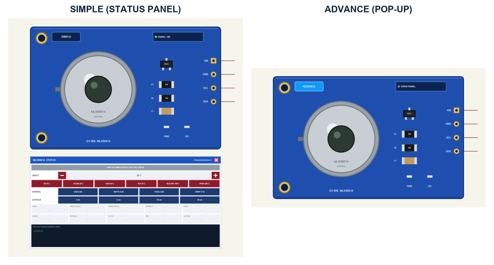
| Simple | Advance | |
|---|---|---|
| Device | MLX90614TEP | MLX90614ADVTEP |
| On the schematic | The module and the STATUS panel | The module |
| The scene | Object, material and distance on the panel | The same, and the room, in the pop-up |
| Status | Banner, 10 readouts, the last 4 events | A pop-up: Sensor, Event log, Tests |
| Interaction | The red X, PANEL on the board | The pop-up, OPEN PANEL on the board |
Download MLX90614 IR Thermometer Library for Proteus
Click the button below to download MLX90614-IR-Thermometer-Library-for-Proteus-v1.0.zip (about 1.29 MB, without the C++ source code of the model):
MLX90614 IR Thermometer Library for Proteus V1.0: GY-906 Non-Contact- README.txt: the devices, installation, the demo, wiring, the test tools and real hardware.
- Proteus Library Files:
TEPMLX90614.LIBandArduinoV4TEP.LIBfrom our Arduino Library for Proteus V4.0. - Proteus Model Files:
TEPMLX90614.DLLandTEPARDUINO.DLL. - Proteus Simulation:
MLX90614-IR-Thermometer-ArduinoUnoV4.pdsprj,MLX90614_Demo.hexand copies of the two DLLs. - Arduino Code:
MLX90614_Demo.ino. It needs the Adafruit MLX90614 Library from the Library Manager of the Arduino IDE, only if you want to change the sketch.
No Proteus yet? Read How to Download and Install Proteus 7 and 8. New to libraries? Follow How to Install a New Library in Proteus.
How to Install MLX90614 IR Thermometer Library for Proteus
- Close Proteus and extract the whole zip file, for example to your Desktop.
- Copy the two files from Proteus Library Files into the LIBRARY folder of Proteus (usually
C:\Program Files (x86)\Labcenter Electronics\Proteus 8 Professional\LIBRARY). - Copy
TEPMLX90614.DLLandTEPARDUINO.DLLfrom Proteus Model Files into the MODELS folder. - Delete
TEPMLX90614.IDXfrom the LIBRARY folder if it is there. - Start Proteus, press P and search for MLX90614.
Tip: keep the Proteus Simulation folder together, because the project needs its .hex file and the DLLs beside it. The library is tested in Proteus 8.5; Proteus 7 is not supported.
The MLX90614 Parts in Proteus
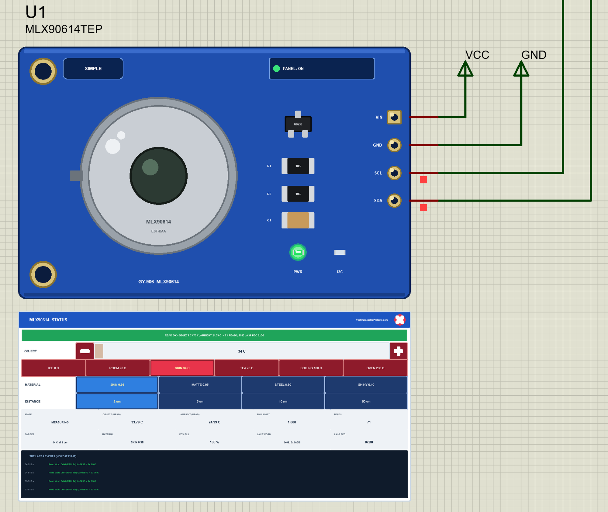
Two LEDs sit on the board: PWR while the module has power, and I2C, which flashes when the Arduino talks to the sensor. Next to the SIMPLE or ADVANCE badge is the panel button. The LEDs, the badge, the button and the panels are TEP additions; the real module has none of them.
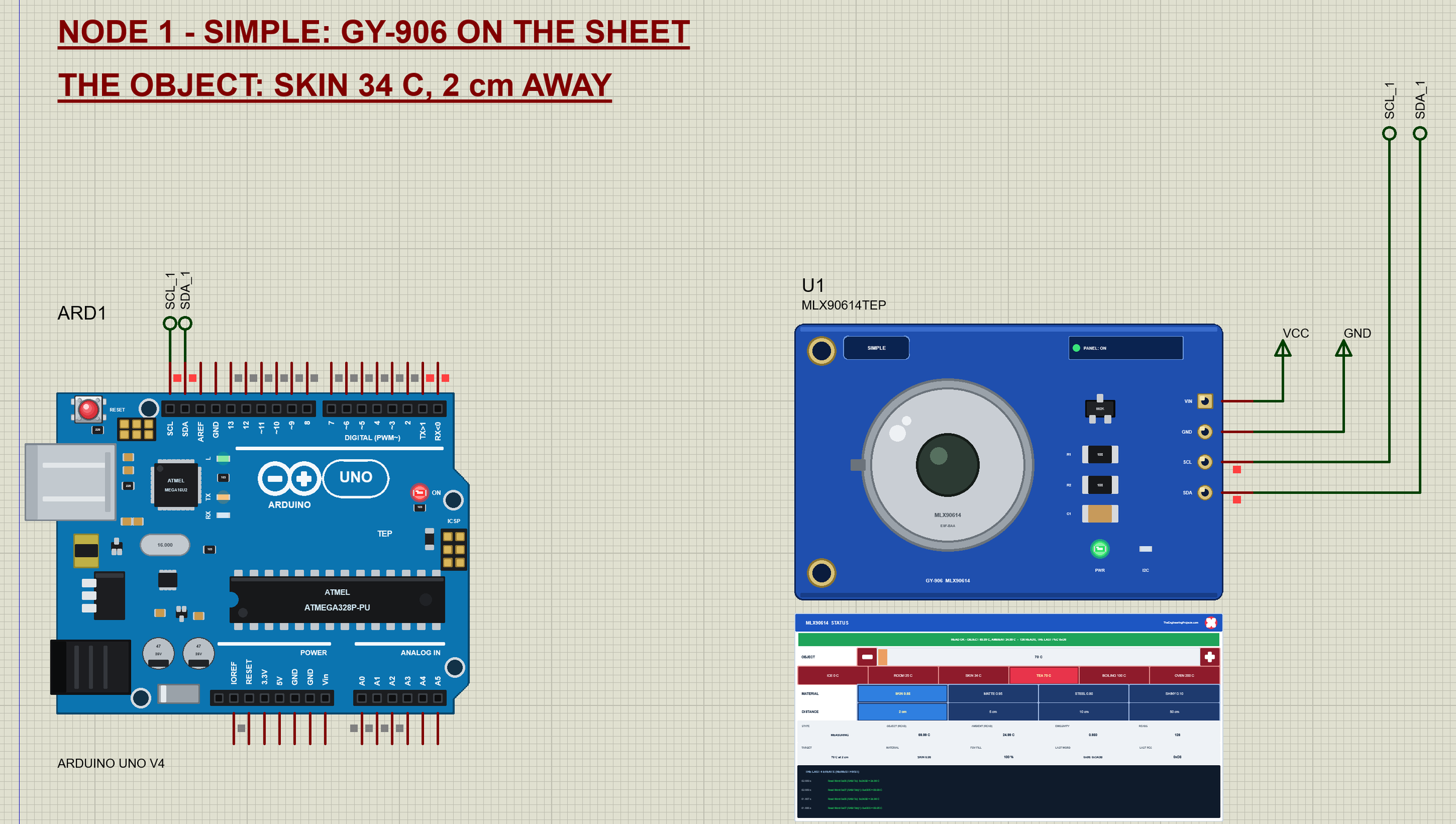
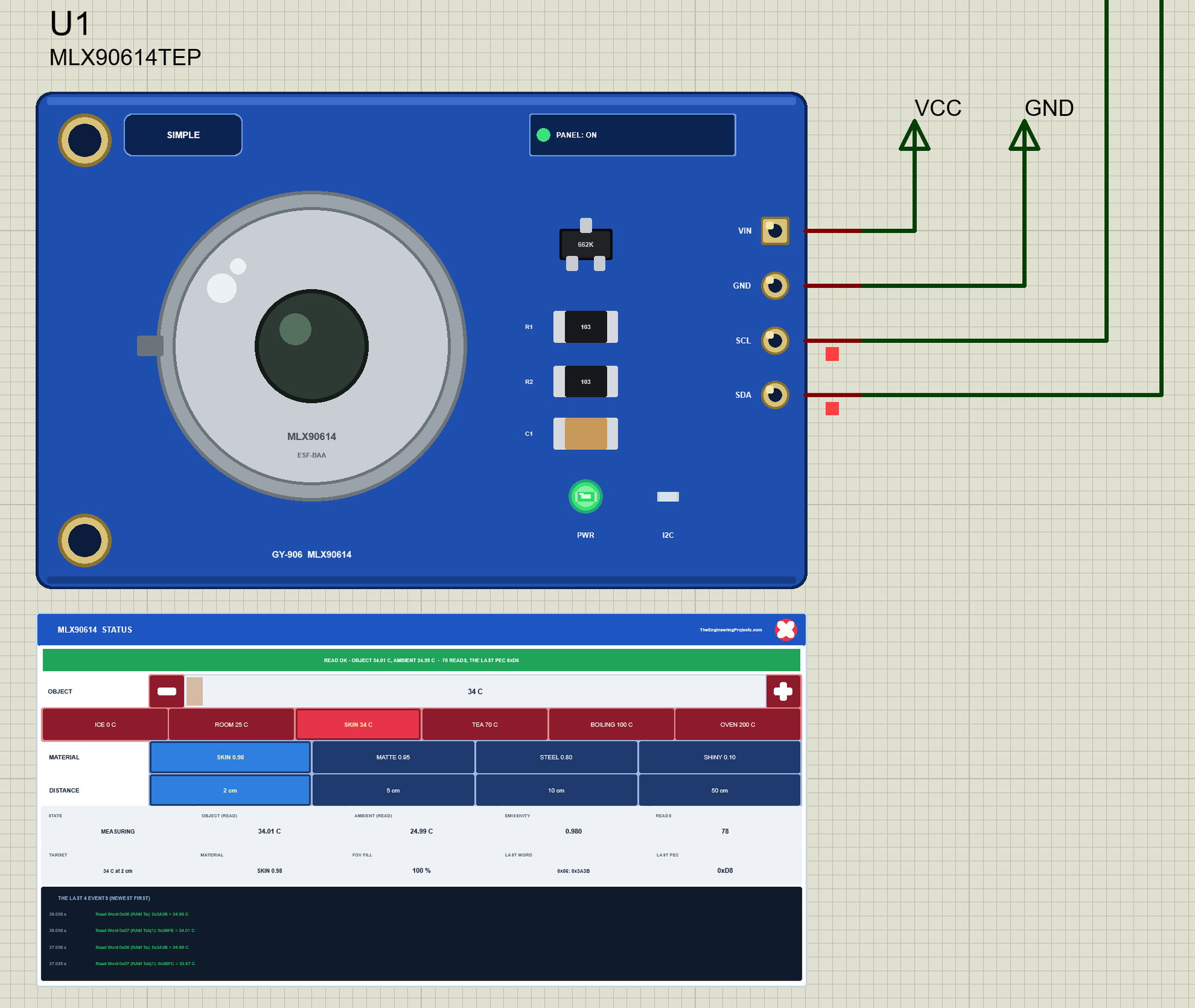
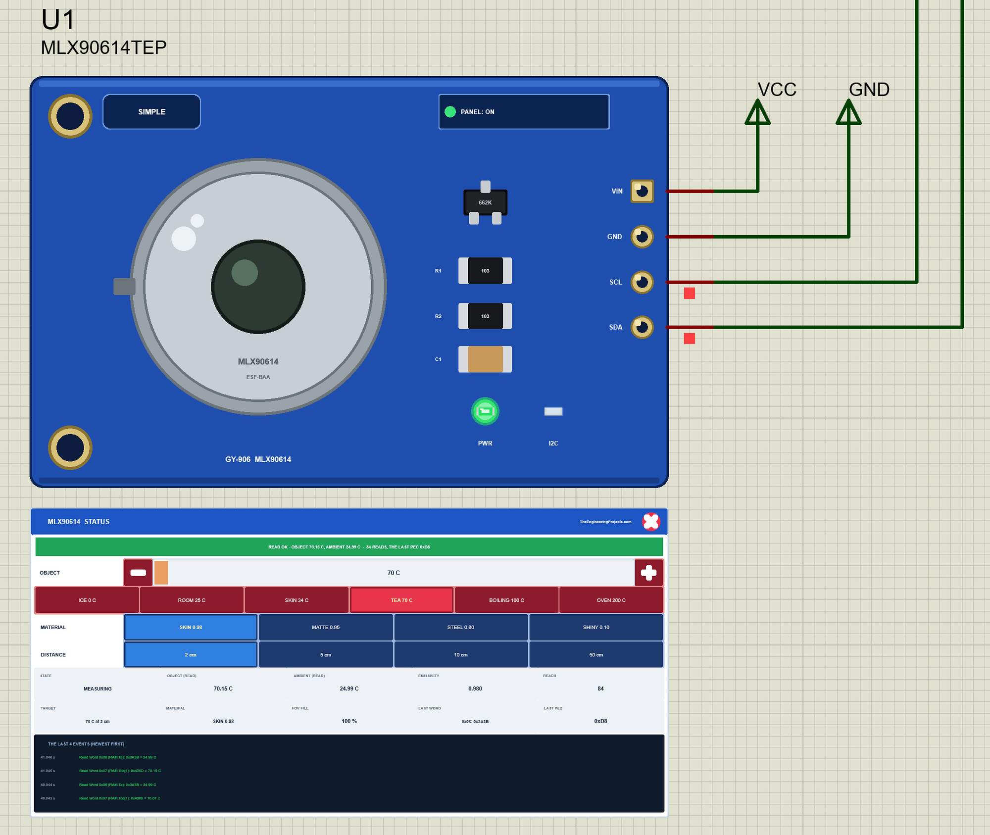
The Simple device adds the STATUS panel. Its banner says what happened last, for example "READ OK - OBJECT 70.15 C, AMBIENT 24.99 C - 84 READS", and turns red with a warning. Under it is the scene: OBJECT with - and + (1 C a click) and six presets, ICE 0 C, ROOM 25 C, SKIN 34 C, TEA 70 C, BOILING 100 C and OVEN 200 C; MATERIAL with SKIN 0.98, MATTE 0.95, STEEL 0.80 and SHINY 0.10; and DISTANCE with 2, 5, 10 and 50 cm. Ten readouts follow: the state, the object and the ambient the sketch read, the emissivity in the EEPROM, the reads, the target, the material, how much of the field of view the object fills, the last word and the last PEC. At the bottom are the last four events.
The red X closes the STATUS panel, and the PANEL button on the board opens it again, so a big project stays readable:
The Advance device keeps the schematic clean: only the module. Its live data opens in a pop-up window at Run, and the OPEN PANEL button on the board brings the window back if you close it. Both devices have the same properties: OBJECT, MATERIAL and DISTANCE for the scene at the start, AMBIENT, the room and the sensor (25 C by default), and NOISE, 0.05 C by default.
The Demo Circuit
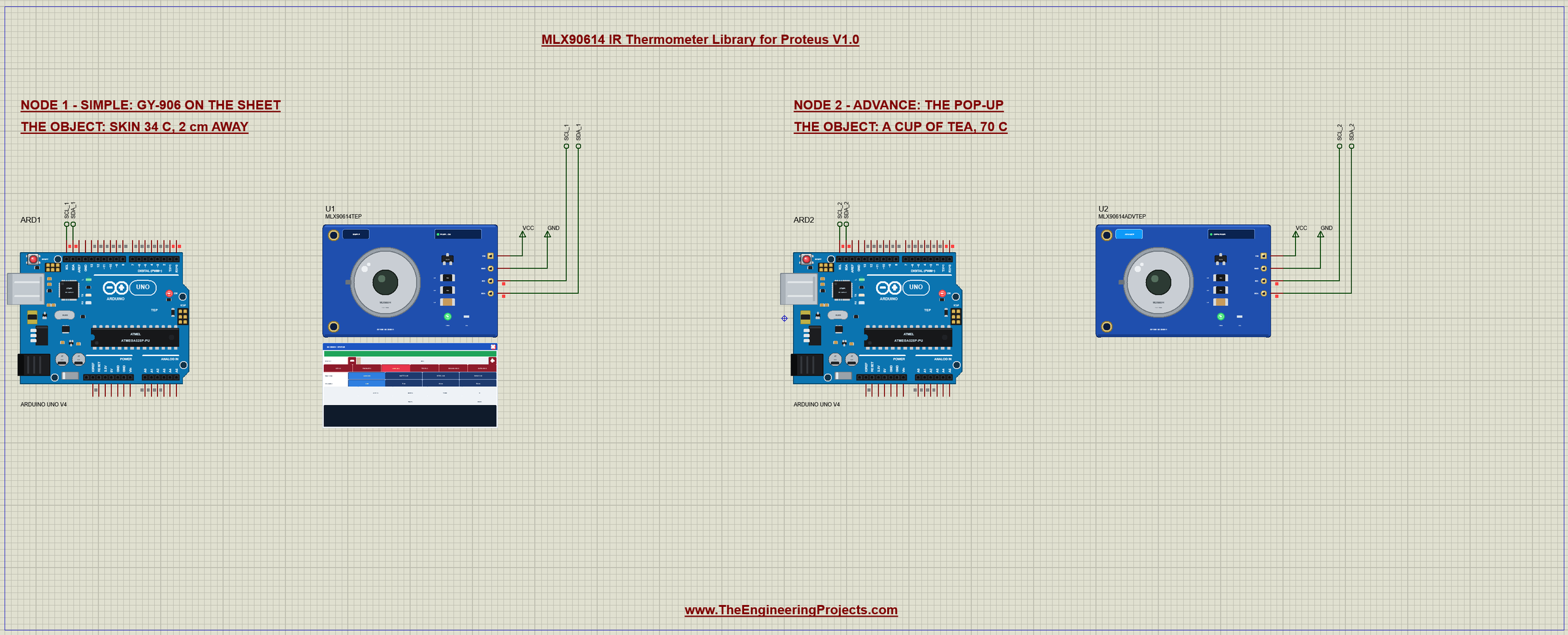
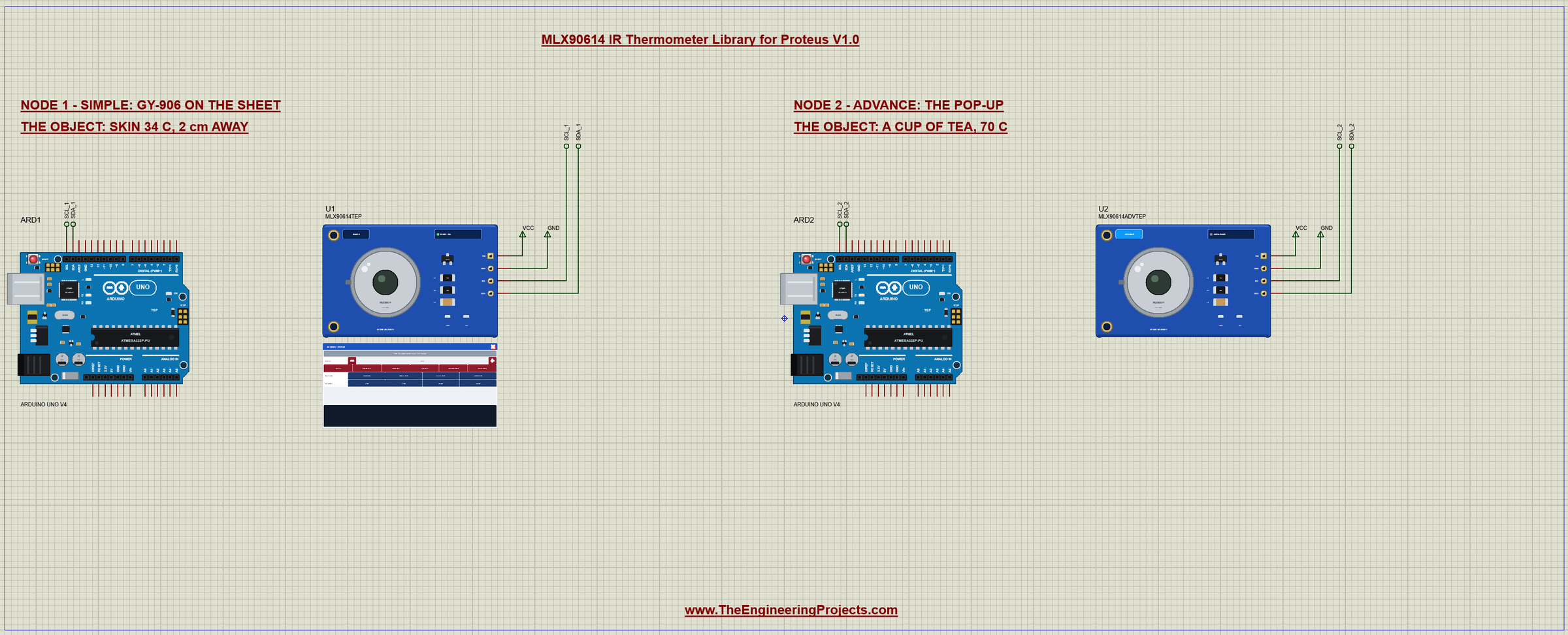
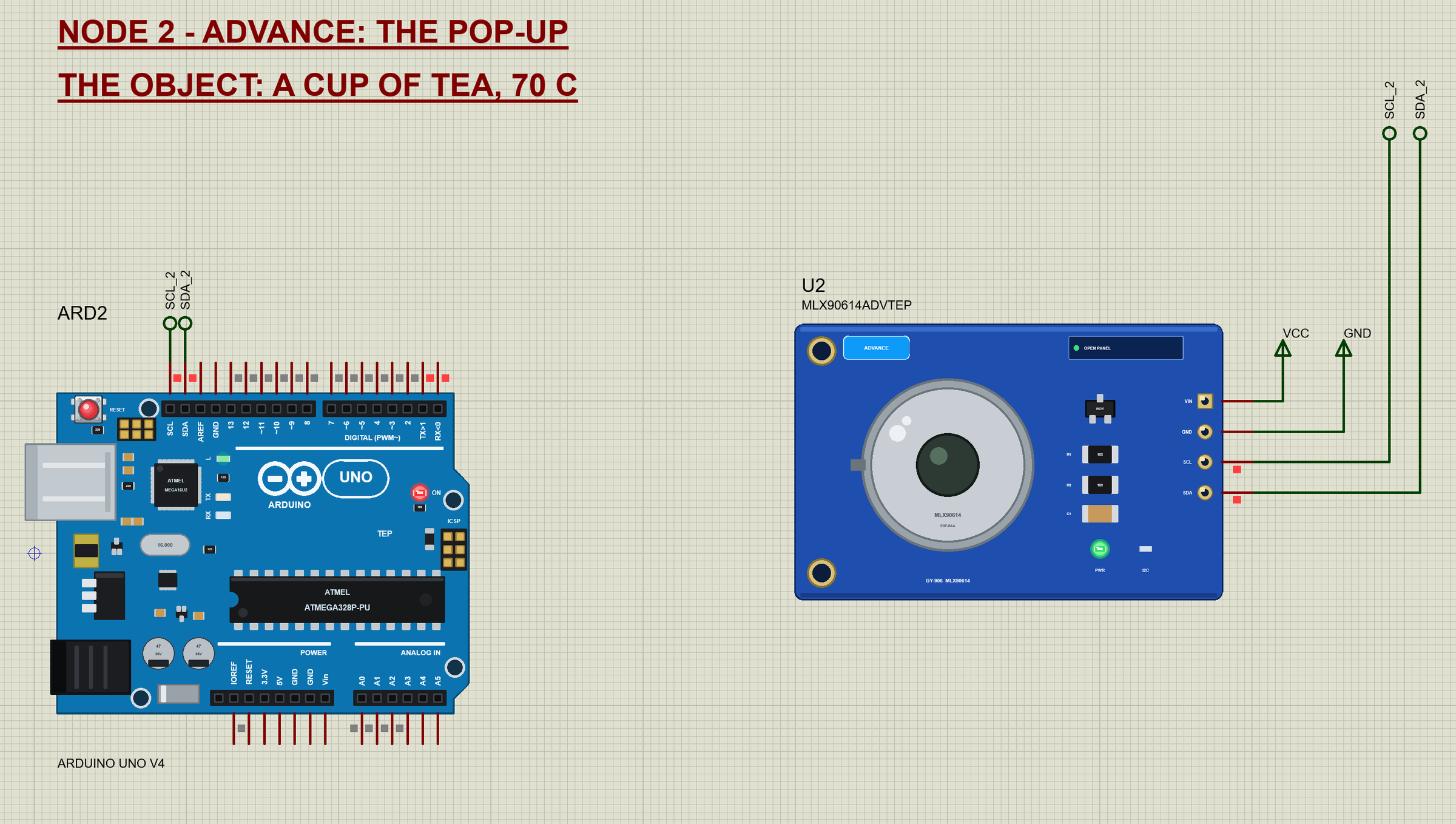
The demo project has two nodes. Each one is an Arduino UNO V4.0 from our Arduino UNO Library for Proteus V4.0 with a GY-906 on its SDA and SCL pins, which are A4 and A5. Both UNOs run the same MLX90614_Demo.hex. Node 1 uses the Simple GY-906 looking at skin, 34 C with an emissivity of 0.98; node 2 uses the Advance GY-906 looking at a cup of tea, 70 C with a matte 0.95. Both are 2 cm away.
Wiring
| GY-906 | Arduino UNO |
|---|---|
| VIN | 5V (the module makes 3.3 V; 3.3 V works too) |
| GND | GND |
| SCL | A5 (the SCL pin next to AREF) |
| SDA | A4 (the SDA pin next to AREF) |
In Proteus, SDA and SCL reach their UNO through net labels, SDA_1 and SCL_1 for node 1 and SDA_2 and SCL_2 for node 2, and VIN and GND go to the VCC and GND terminals. The UNO V4.0 has its SDA and SCL pins on the top header, as on the real board. The Wire library turns on the UNO's internal pull-ups, which hold the bus HIGH in the simulation. The serial monitor needs no wires at all, because it is built into the UNO V4.0.
The Two Nodes Up Close
The Arduino Code
The demo sketch uses the Adafruit MLX90614 Library (version 2.1.7) with Adafruit BusIO. New to Arduino? Start with Arduino Tutorial for Beginners and Introduction to Arduino UNO. The sketch begins with Wire and the library:
#include <Wire.h>
#include <Adafruit_MLX90614.h>
Then the address and the sensor object:
const uint8_t MLX_ADDR = 0x5A;                 // the MLX90614's SMBus address (the factory default)

Adafruit_MLX90614 mlx;
In setup(), begin() checks that the sensor answers at its address, and the sketch waits for the first measurement, which comes 250 ms after power-up:
  if (!mlx.begin(MLX_ADDR)) Serial.println(F("MLX90614 not found - check the wiring"));
  delay(300);                                  // the first measurement comes 250 ms after power-up
A reading is two calls. readObjectTempC() reads RAM 0x07 and readAmbientTempC() RAM 0x06; each returns NAN when the read failed. The sketch prints both every second:
void readTemps() {
  const double obj = mlx.readObjectTempC();
  const double amb = mlx.readAmbientTempC();
  Serial.print('#'); Serial.print(++count);
  if (isnan(obj) || isnan(amb)) {
    Serial.println(F("  no answer from the MLX90614 (check VIN, GND, SDA = A4, SCL = A5)"));
    return;
  }
  Serial.print(F("  Object ")); Serial.print(obj, 2);
  Serial.print(F(" C   Ambient ")); Serial.print(amb, 2); Serial.println(F(" C"));
}
EMIS 0.95 writes the emissivity into the sensor's EEPROM. writeEmissivity() erases the cell, waits 10 ms, writes the new value and waits 10 ms again, each with the right PEC:
void emissivity(const char* arg) {
  const double e = atof(arg);
  if (e < 0.1 || e > 1.0) { Serial.println(F("EMIS: 0.10 to 1.00")); return; }
  mlx.writeEmissivity(e);                      // erase, 10 ms, write, 10 ms
  Serial.print(F("EMIS: ")); Serial.println(mlx.readEmissivity(), 3);
}
RAW reads the object's word by hand with Wire. endTransmission(false) leaves the bus without a STOP, so requestFrom() starts with the repeated START the MLX90614 needs. Then the sketch checks the PEC itself, which the Adafruit library does not do:
void raw() {
  Wire.beginTransmission(MLX_ADDR);
  Wire.write(0x07);                            // RAM 0x07: the object (Tobj1)
  if (Wire.endTransmission(false) != 0) { Serial.println(F("RAW: no ACK")); return; }   // false: the repeated start
  if (Wire.requestFrom(MLX_ADDR, (uint8_t)3) != 3) { Serial.println(F("RAW: no data")); return; }
  const uint8_t lsb = Wire.read(), msb = Wire.read(), pec = Wire.read();
  const uint8_t frame[5] = {(uint8_t)(MLX_ADDR << 1), 0x07, (uint8_t)(MLX_ADDR << 1 | 1), lsb, msb};
  const uint16_t w = (uint16_t)msb << 8 | lsb;
  Serial.print(F("RAW: ")); printHex(w, 4);
  Serial.print(F(" x 0.02 - 273.15 = ")); Serial.print(w * 0.02 - 273.15, 2);
  Serial.print(F(" C  PEC ")); printHex(pec, 2);
  Serial.println(crc8(frame, 5) == pec ? F(" OK") : F(" WRONG"));
}
The PEC is the SMBus CRC-8, eight shifts per byte with the polynomial 0x07:
uint8_t crc8(const uint8_t* d, uint8_t n) {
  uint8_t crc = 0;
  while (n--) {
    uint8_t in = *d++;
    for (uint8_t i = 0; i < 8; i++) {
      const uint8_t carry = (crc ^ in) & 0x80;
      crc <<= 1;
      if (carry) crc ^= 0x07;
      in <<= 1;
    }
  }
  return crc;
}
The HEX file is in the package, so you do not need the Arduino IDE to run the demo. To change the sketch, install "Adafruit MLX90614 Library" from the Library Manager, open the sketch in the Arduino IDE and export the compiled binary, as in How to get the HEX file from Arduino. It needs 11,848 bytes of flash and 507 bytes of RAM.
The Serial Monitor
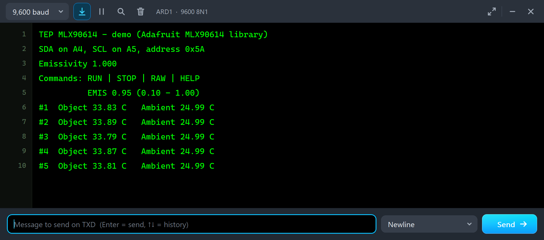
Both UNOs have the serial monitor built in, and it opens at Run. The screenshots use its Simple interface. Node 1 starts like this:
TEP MLX90614 - demo (Adafruit MLX90614 library)
SDA on A4, SCL on A5, address 0x5A
Emissivity 1.000
Commands: RUN | STOP | RAW | HELP
          EMIS 0.95 (0.10 - 1.00)
#1  Object 33.83 C   Ambient 24.99 C
#2  Object 33.89 C   Ambient 24.99 C
#3  Object 33.79 C   Ambient 24.99 C
The skin is at 34 C, but the readings say about 33.8 C. That is no bug: the sketch printed "Emissivity 1.000", the factory value, while skin has 0.98. The sensor sees a little less infra-red than a perfect black object at 34 C would send, and reads a little low. The ambient is the sensor itself, the room at 25 C. Node 2 shows the same with the matte cup of tea at 70 C:
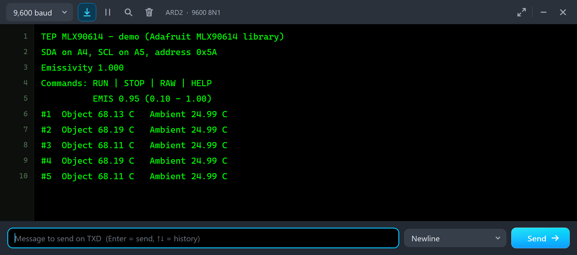
A matte cup has 0.95, so the reading is about 2 C low. Type a command in the monitor and press Enter: STOP stops the readings, RUN starts them again, and EMIS and RAW are explained below. HELP lists them all.
Set the Emissivity
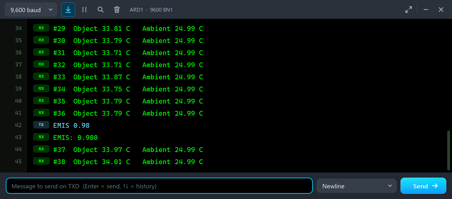
So let's tell the sensor what it looks at. We typed EMIS 0.98 on node 1:
#35  Object 33.79 C   Ambient 24.99 C
#36  Object 33.79 C   Ambient 24.99 C
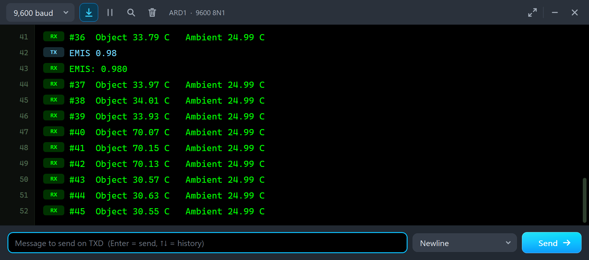
EMIS 0.98
EMIS: 0.980
#37  Object 33.97 C   Ambient 24.99 C
#38  Object 34.01 C   Ambient 24.99 C
The sketch wrote 0xFAE0 into the EEPROM, the sensor's next measurements used it, and the readings went to 34 C, the skin's real temperature. The STATUS panel shows the new emissivity, 0.980, in its EMISSIVITY readout:
Change the Scene on the STATUS Panel
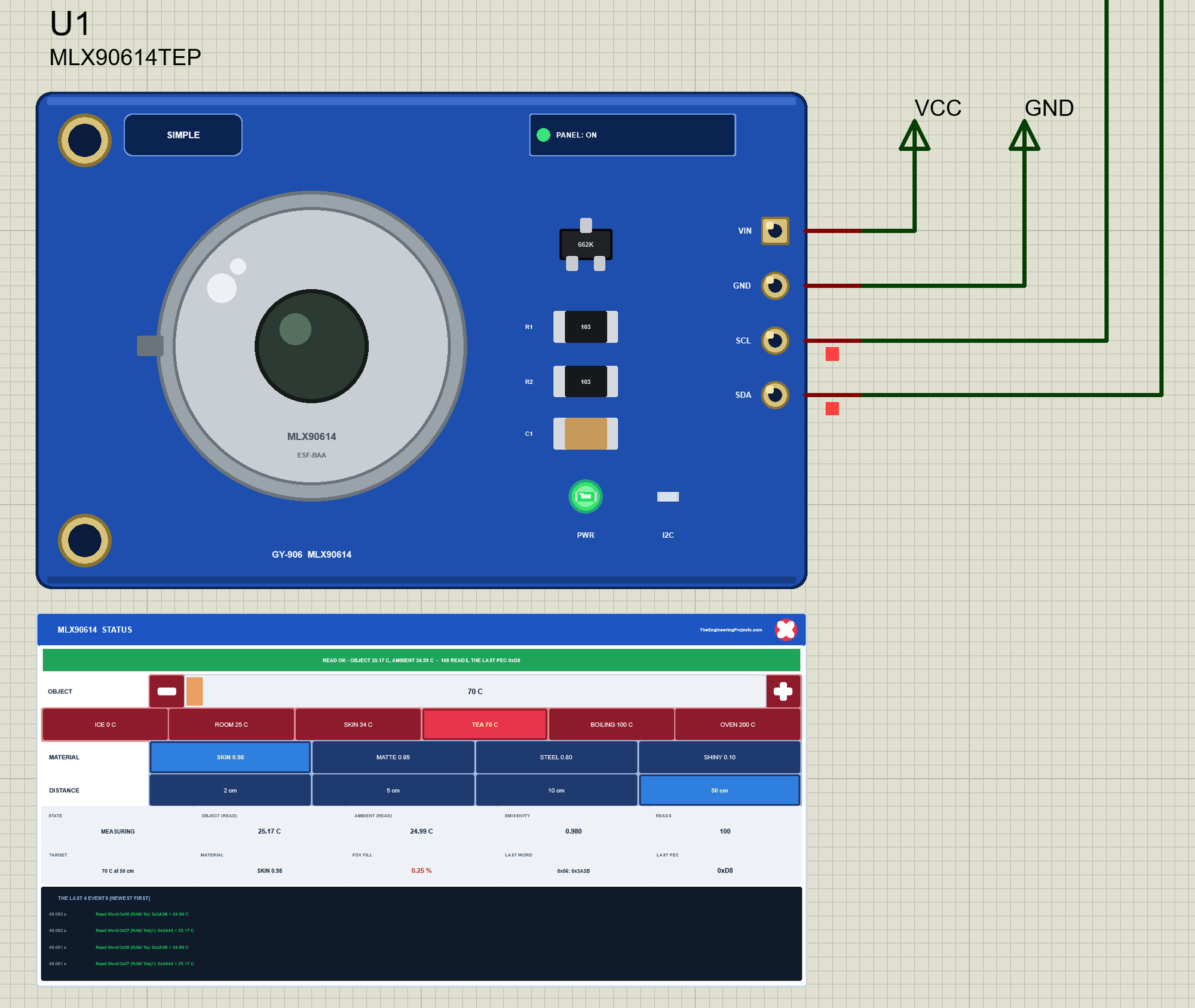
Now let's point the sensor at other things while the simulation runs. We clicked TEA 70 C on U1's STATUS panel with the mouse:
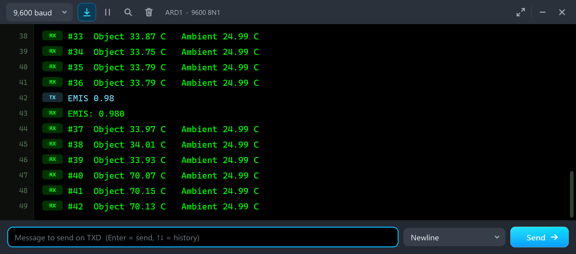
#38  Object 34.01 C   Ambient 24.99 C
#39  Object 33.93 C   Ambient 24.99 C
#40  Object 70.07 C   Ambient 24.99 C
#41  Object 70.15 C   Ambient 24.99 C
#42  Object 70.13 C   Ambient 24.99 C
The object is still skin, 0.98, and the EEPROM says 0.98, so the reading is right on. Then we clicked SHINY 0.10, as if the cup were polished metal:
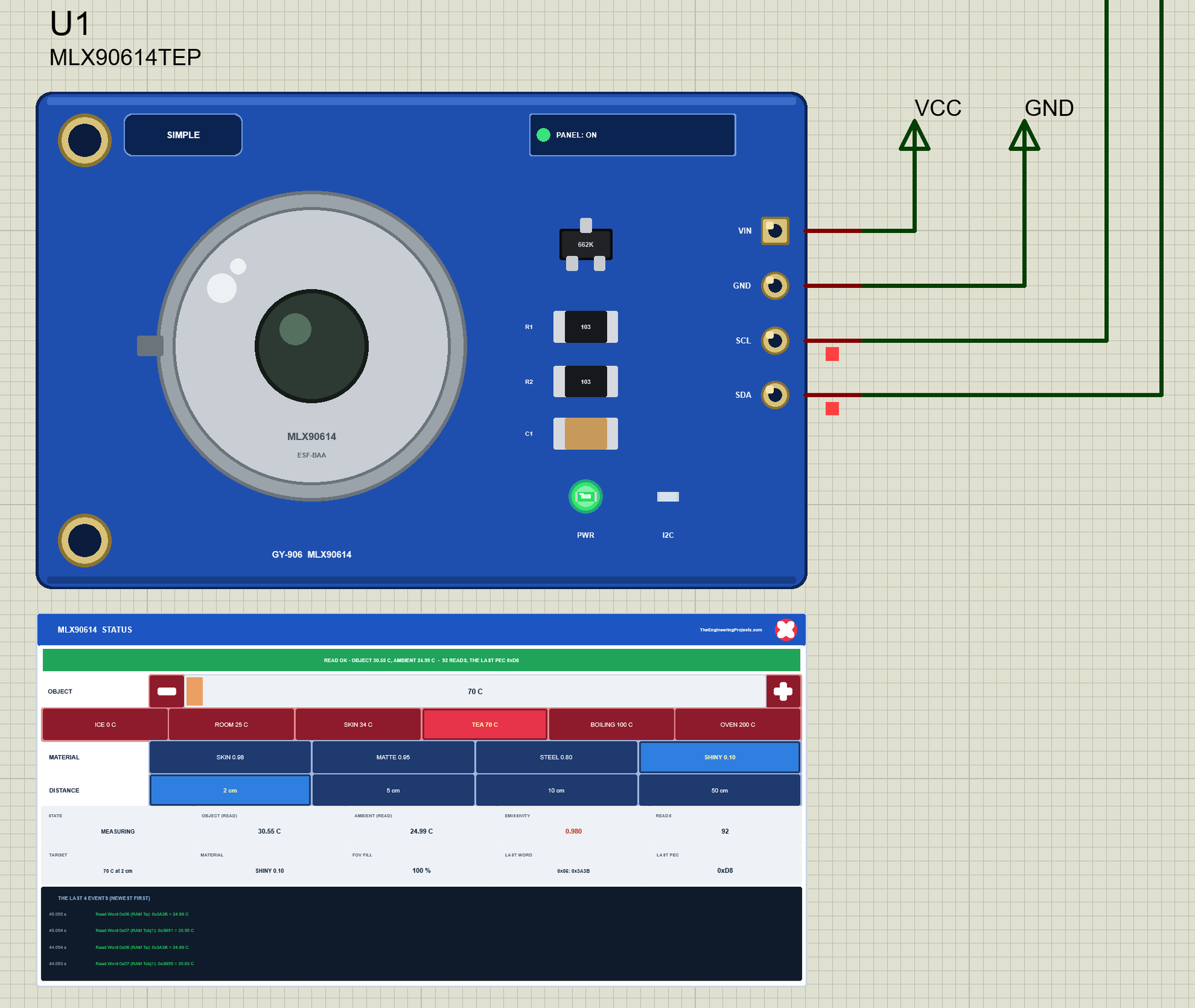
#42  Object 70.13 C   Ambient 24.99 C
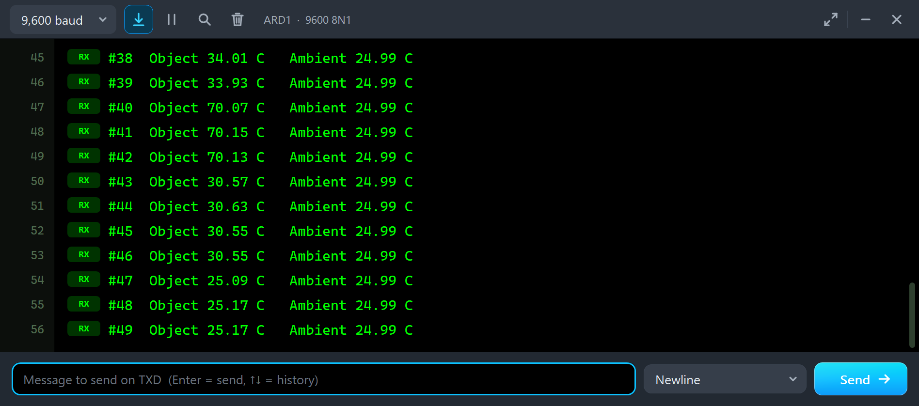
#43  Object 30.57 C   Ambient 24.99 C
#44  Object 30.63 C   Ambient 24.99 C
#45  Object 30.55 C   Ambient 24.99 C
The object is just as hot, but a shiny surface sends only a tenth of the infra-red, and the sensor still assumes 0.98. So it reads 30.6 C, much closer to the room. That is the classic IR thermometer mistake with metal: paint it matte, put tape on it, or set the emissivity. Next we went back to SKIN 0.98 and clicked 50 cm:
#45  Object 30.55 C   Ambient 24.99 C
#46  Object 30.55 C   Ambient 24.99 C
#47  Object 25.09 C   Ambient 24.99 C
#48  Object 25.17 C   Ambient 24.99 C
#49  Object 25.17 C   Ambient 24.99 C
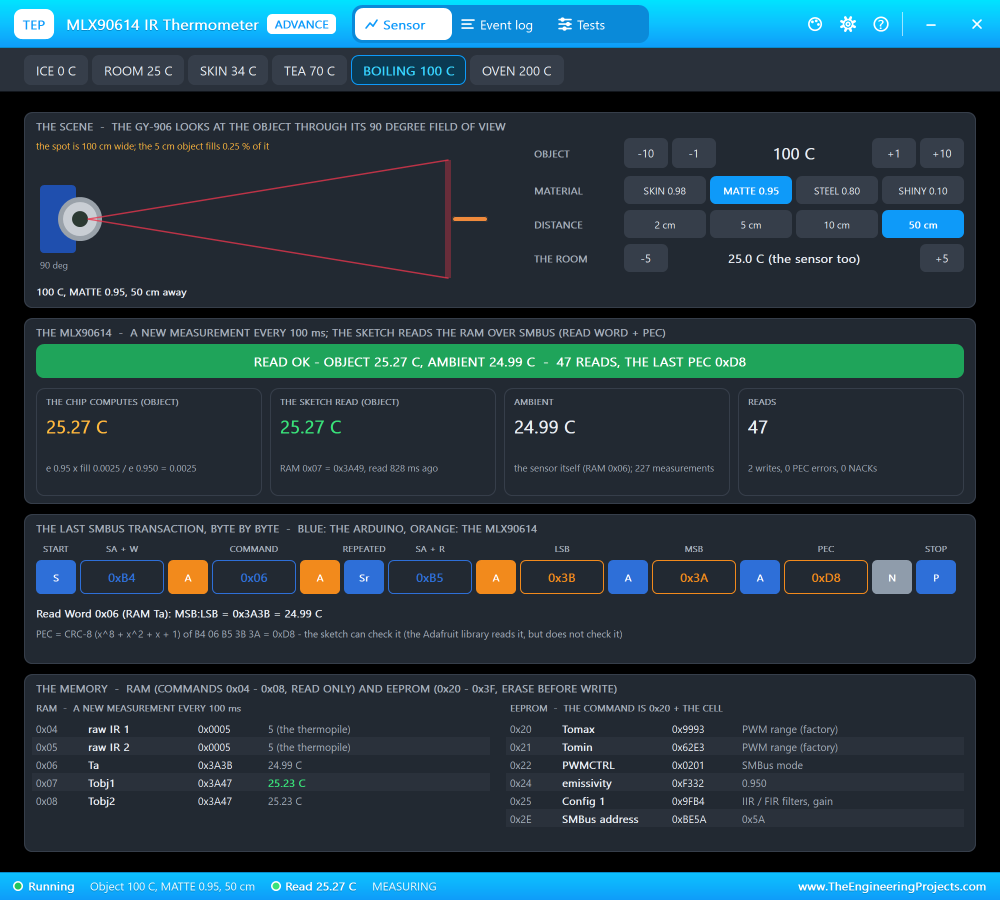
At 50 cm the 90 degree spot is a metre wide, and the 5 cm object fills only 0.25 % of it. The rest is the room, so the sensor reads 25.1 C. Hold the sensor close: closer than half the object's width. A click on 2 cm brings the 70 C back.
The Advance Pop-Up Window
At Run, the Advance GY-906 opens its own window, MLX90614 IR Thermometer, with the look of our TEP Serial Monitor Advance for Proteus. It has three tabs, Sensor, Event log and Tests, plus Settings and Help behind the gear and question mark icons. The status bar at the bottom always shows the object, the last reading and the state.
The Sensor Page
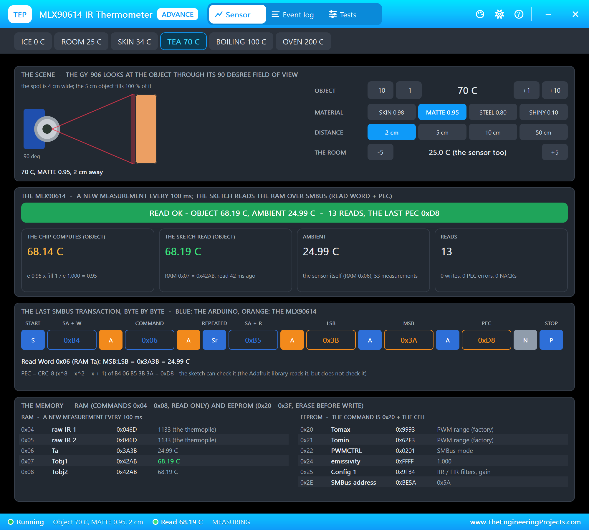
The toolbar carries the six object presets. The top card is the scene: the sensor, its 90 degree cone and the object at its distance, coloured by its temperature, with OBJECT -10, -1, +1 and +10, MATERIAL, DISTANCE and THE ROOM -5 and +5 on the right. The next card is the MLX90614: the banner, what the chip computes from the scene with the ratio worked out, what the sketch read, the ambient and the reads.
Under them, the last SMBus transaction is drawn byte by byte, blue for the Arduino and orange for the sensor: START, 0xB4, ACK, the command, ACK, the repeated START, 0xB5, ACK, the low byte, the high byte, the PEC, the Arduino's NACK and the STOP, with the word and the PEC worked out below. The last card is the memory: the RAM words and the EEPROM cells with what they mean.
Emissivity on Node 2
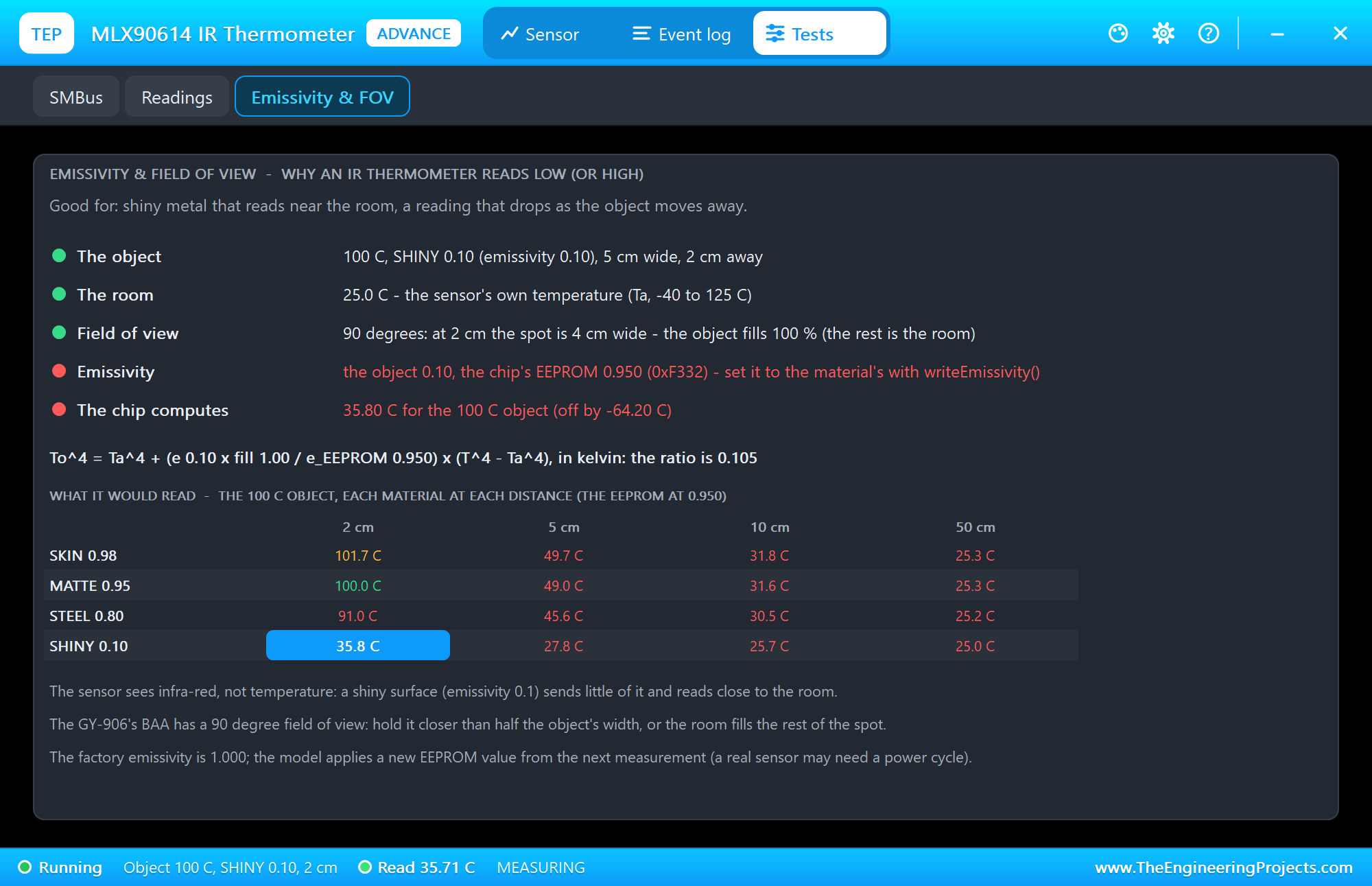
We clicked BOILING 100 C in the pop-up. The reading went to about 97.2 C, and the Emissivity and FOV tool explains why:
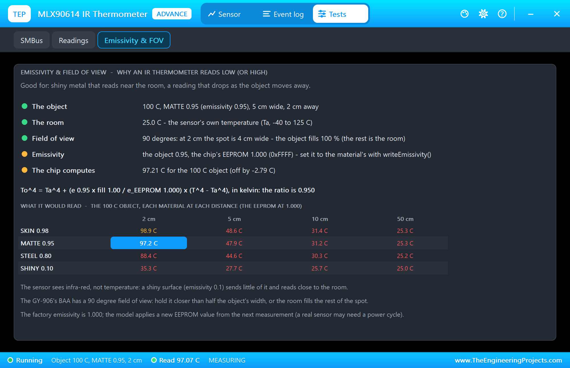
It lists the object, the room, the field of view, the object's emissivity against the EEPROM's and what the chip computes, then the formula with the numbers, and a table of what the sensor would read for each material at each distance. Open it for shiny metal that reads near the room or a reading that drops as the object moves away. Then we typed EMIS 0.95 on node 2:
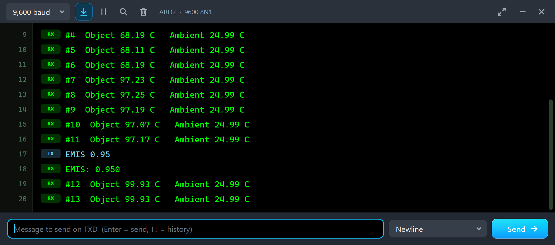
#6  Object 68.19 C   Ambient 24.99 C
#7  Object 97.23 C   Ambient 24.99 C
#8  Object 97.25 C   Ambient 24.99 C
#9  Object 97.19 C   Ambient 24.99 C
#10  Object 97.07 C   Ambient 24.99 C
#11  Object 97.17 C   Ambient 24.99 C
EMIS 0.95
EMIS: 0.950
#12  Object 99.93 C   Ambient 24.99 C
#13  Object 99.93 C   Ambient 24.99 C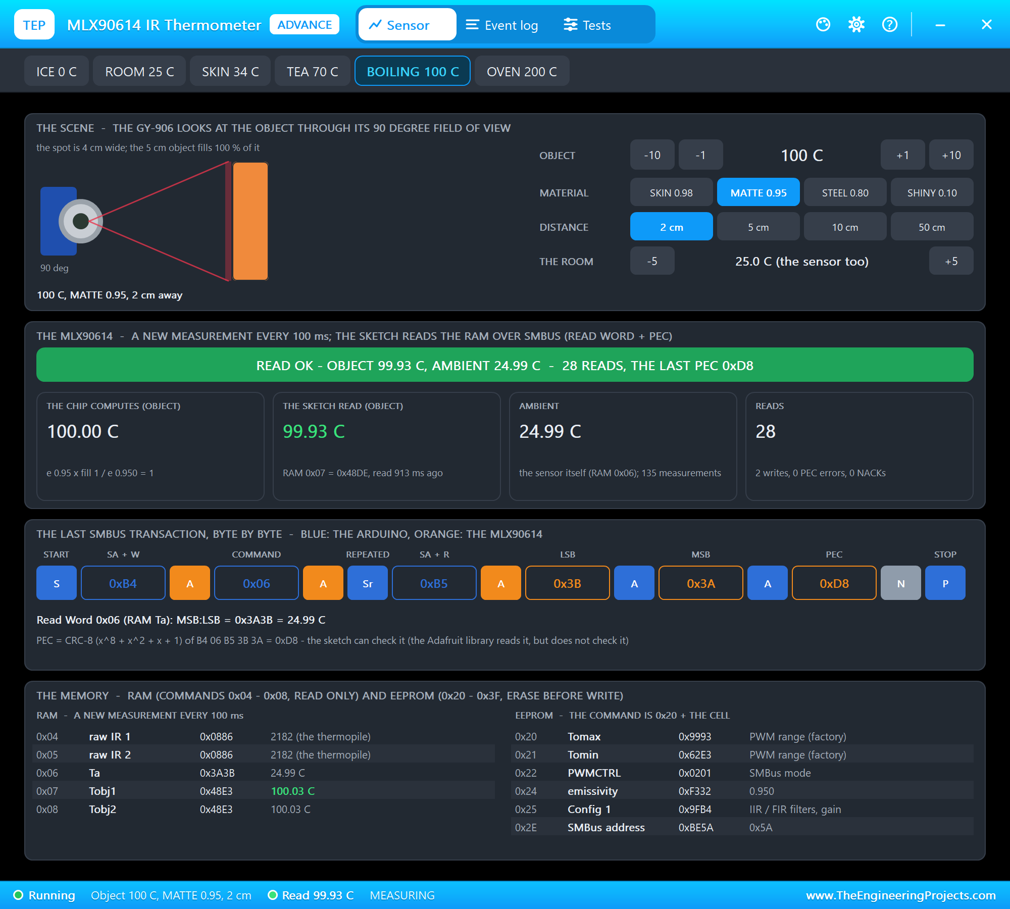
The memory card shows the new cell: 0xF332, 62258 / 65535 = 0.950. RAW reads the object's word by hand and checks its PEC:
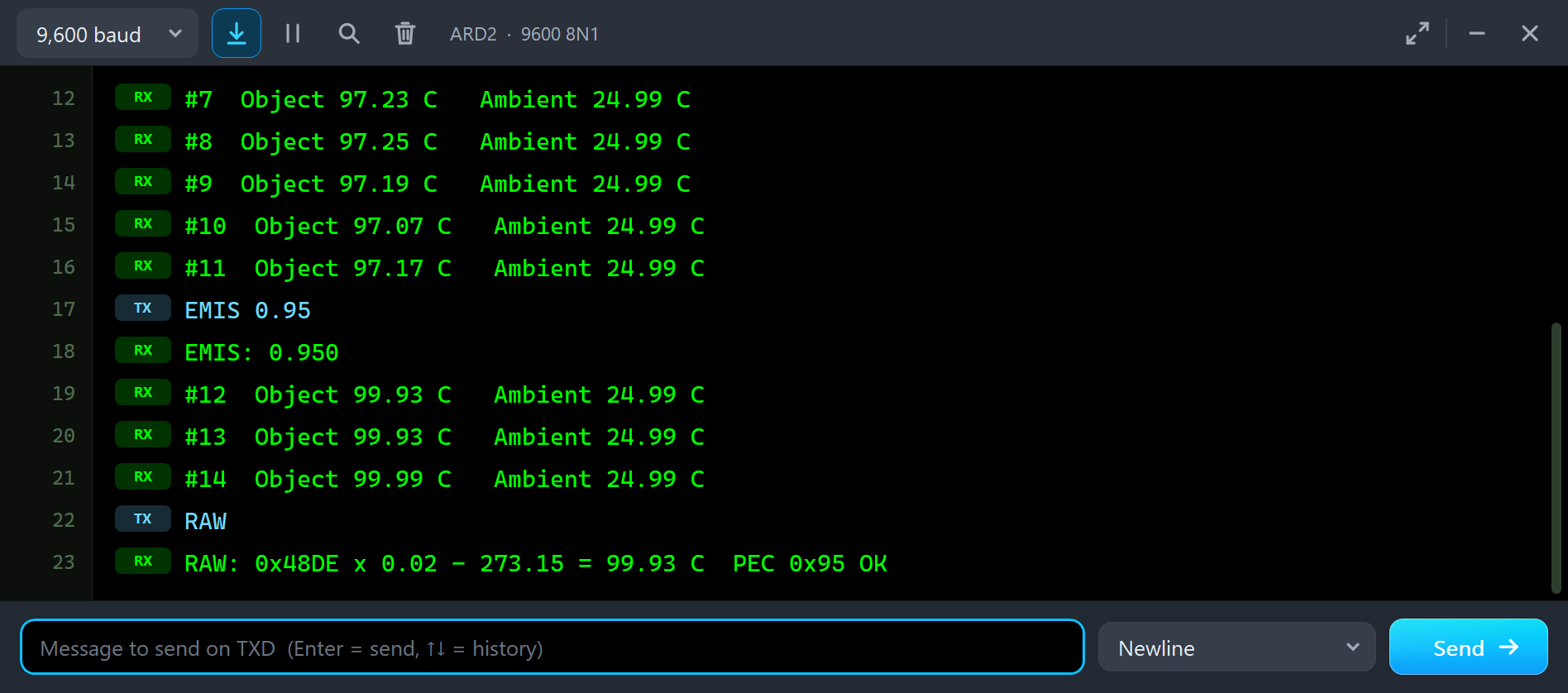
#12  Object 99.93 C   Ambient 24.99 C
#13  Object 99.93 C   Ambient 24.99 C
#14  Object 99.99 C   Ambient 24.99 C
RAW
RAW: 0x48DE x 0.02 - 273.15 = 99.93 C  PEC 0x95 OK
The word is 0x48DE: 18654 x 0.02 = 373.08 K, minus 273.15 = 99.93 C. The PEC 0x95 is the CRC-8 of B4 07 B5 DE 48: the address with the write bit, the command, the address with the read bit and the two data bytes. The sketch worked out the same CRC itself, so it printed OK. A garbled bit on a long cable would show up here as WRONG.
Shiny and Far on Node 2
With SHINY 0.10 in the pop-up, the Emissivity and FOV tool turns red: the object 0.10 against the EEPROM's 0.950, and the chip computing about 35.8 C for the 100 C object. Its table shows at a glance that only the matching material at 2 cm reads right:
Back on MATTE 0.95, we clicked 50 cm. The scene card draws the wide cone and the tiny object in it:
The Test Tools
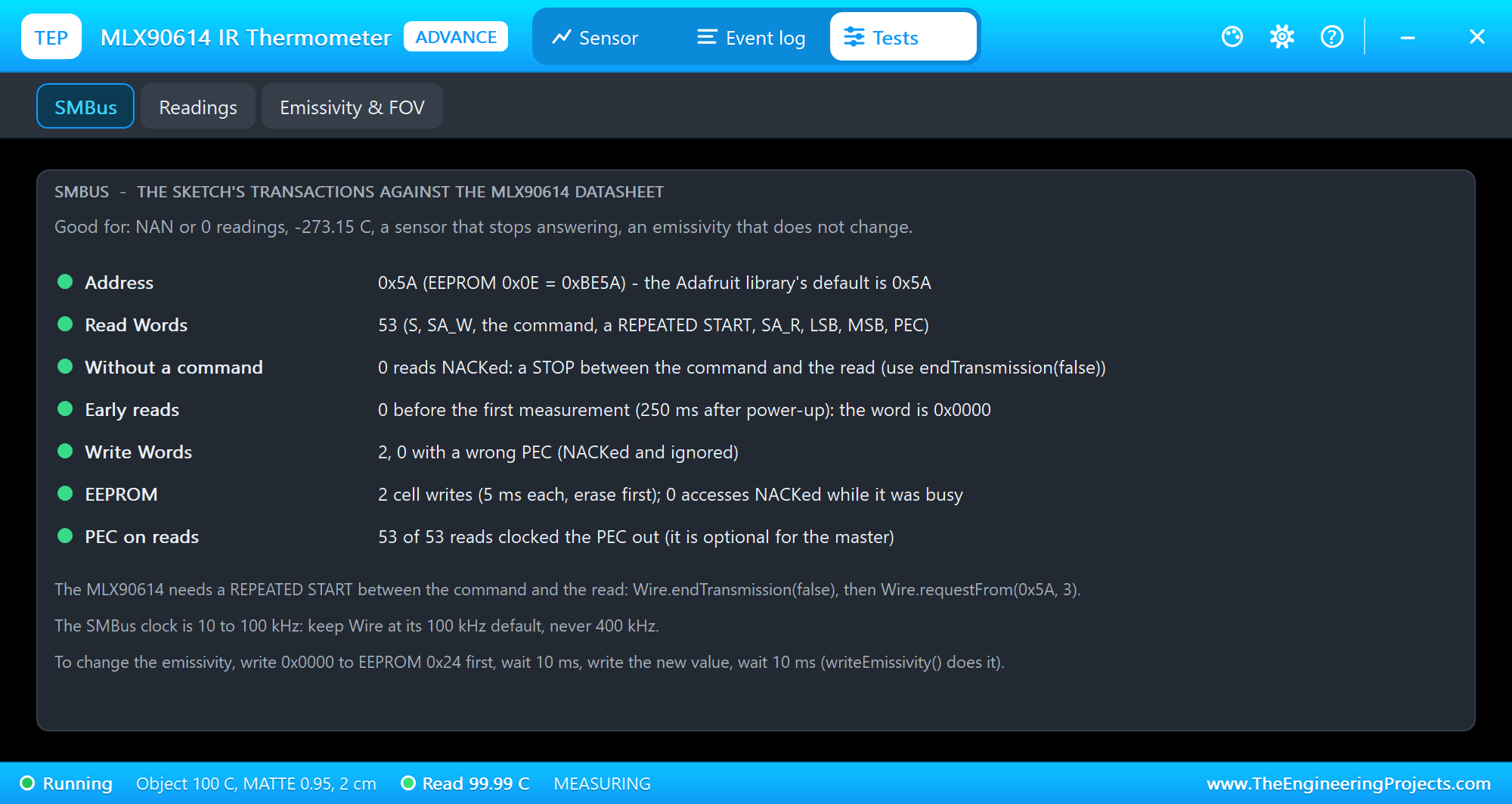
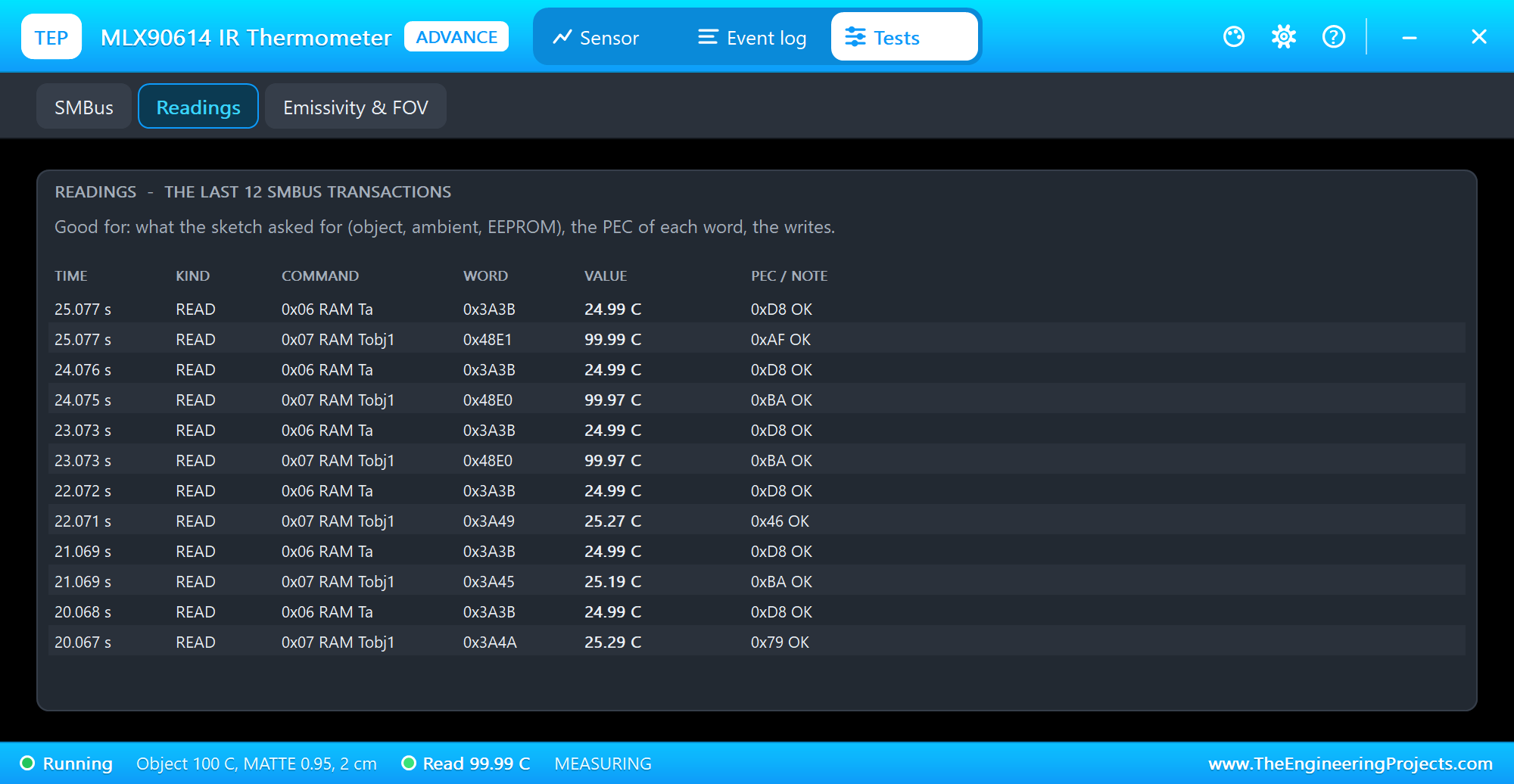
The SMBus tool is the one to open for NAN or 0 readings, -273.15 C, a sensor that stops answering or an emissivity that does not change. It checks the address, the Read Words, the reads NACKed for a missing repeated start, the reads before the first measurement, the Write Words and their PEC, the EEPROM writes and the accesses while the EEPROM was busy. The Readings tool lists the last 12 transactions:
The Event Log
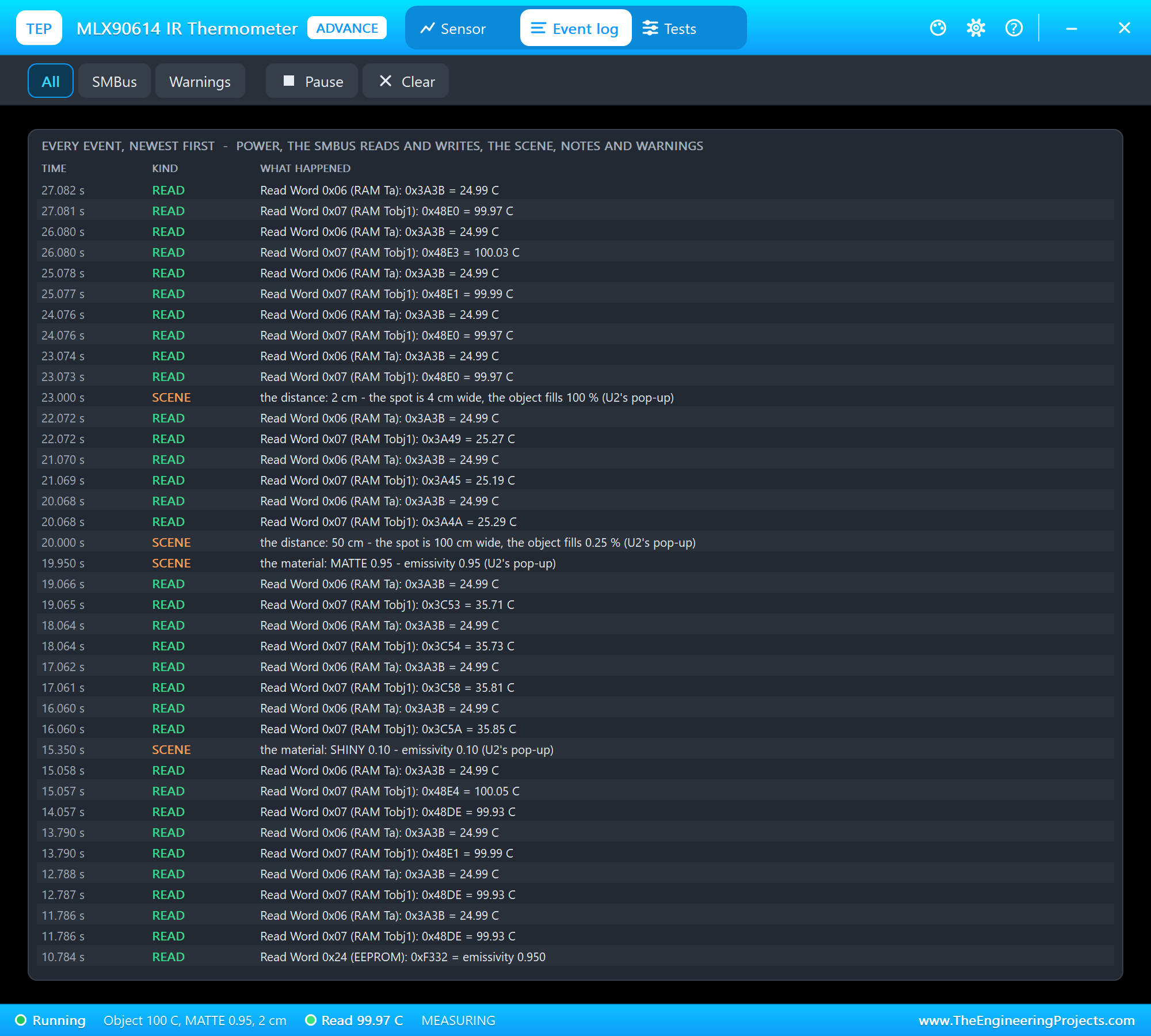
The Event log lists everything that happened, newest first: the power, the first measurement, every Read Word and Write Word, the scene's changes with where they came from, notes and warnings. Filter it by SMBus or warnings, pause it, or clear it.
Classic MLX90614 Mistakes, Simulated
Besides emissivity and distance, the model catches the SMBus mistakes that make an MLX90614 project fail on the desk. They are in the model and in our automatic tests, not in the screenshots above:
- No repeated start: a sketch that ends the command with a STOP,
Wire.endTransmission()instead ofendTransmission(false), loses the command; the MLX90614 NACKs the read, and a red warning says why. - Too early: a read in the first 250 ms after power-up gets 0x0000, and the Adafruit library returns NAN.
- A wrong PEC: a Write Word with a wrong PEC is NACKed and ignored.
- No erase: an EEPROM cell must be written 0x0000 first; a new value written over an old one is ignored.
- Too fast after a write: an EEPROM erase or write takes 5 ms, and the sensor NACKs its address meanwhile; writeEmissivity() waits 10 ms.
The Simulation Log
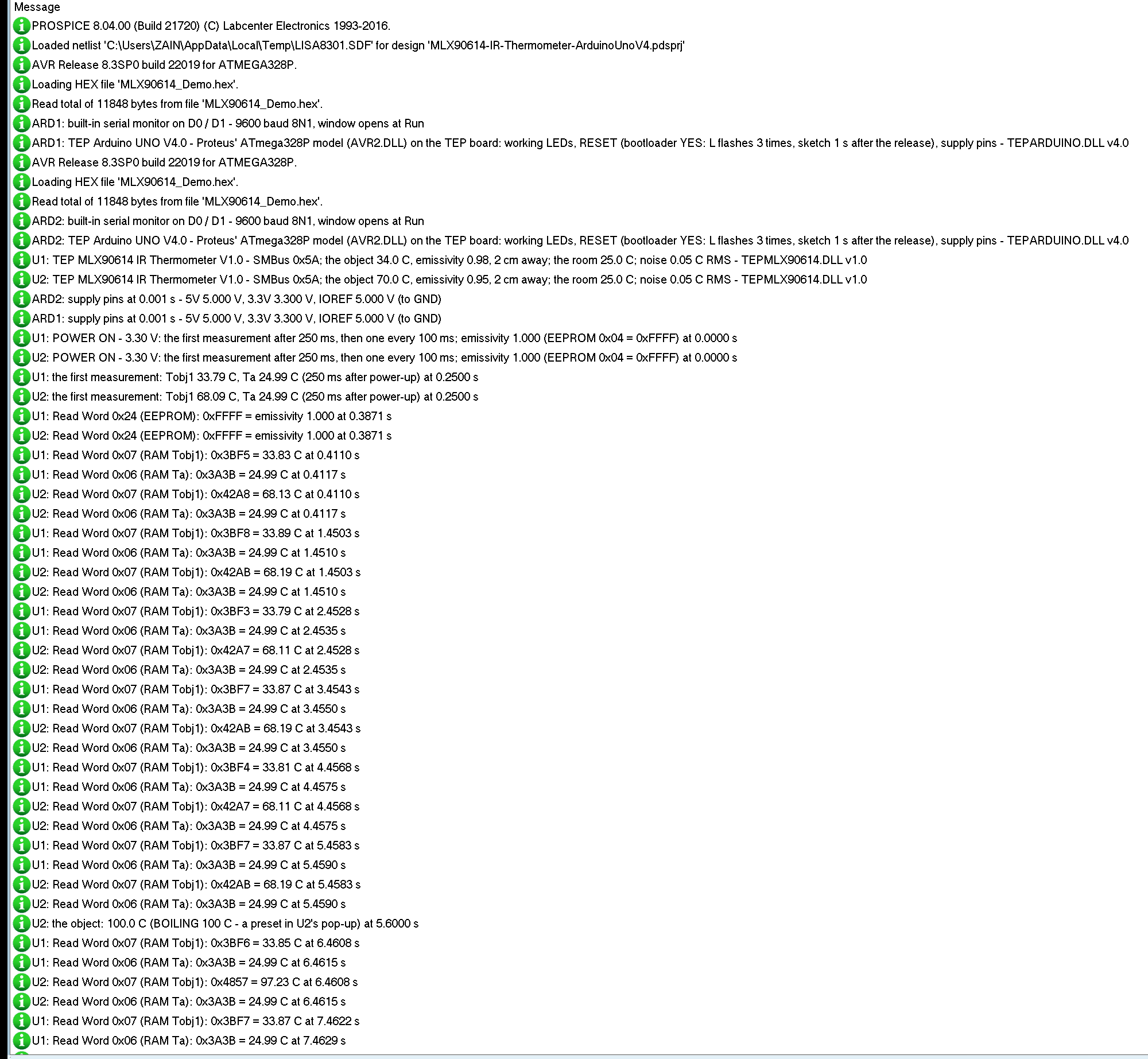
Every GY-906 also writes to the simulation log of Proteus, with the exact simulation time. This part shows the start of node 1:
U1: TEP MLX90614 IR Thermometer V1.0 - SMBus 0x5A; the object 34.0 C, emissivity 0.98, 2 cm away; the room 25.0 C; noise 0.05 C RMS - TEPMLX90614.DLL v1.0
U1: POWER ON - 3.30 V: the first measurement after 250 ms, then one every 100 ms; emissivity 1.000 (EEPROM 0x04 = 0xFFFF) at 0.0000 s
U1: the first measurement: Tobj1 33.79 C, Ta 24.99 C (250 ms after power-up) at 0.2500 s
U1: Read Word 0x24 (EEPROM): 0xFFFF = emissivity 1.000 at 0.3871 s
U1: Read Word 0x07 (RAM Tobj1): 0x3BF5 = 33.83 C at 0.4110 s
U1: Read Word 0x06 (RAM Ta): 0x3A3B = 24.99 C at 0.4117 s
The module reports its scene, powers up at once, and makes its first measurement 250 ms later. At 0.3871 s the sketch reads the emissivity from the EEPROM, then the object and the ambient once a second.
How the Model Works
The model is digital. VIN and GND power the module, and SCL and SDA are open-drain lines: the model pulls SDA LOW to acknowledge and to send, and releases it otherwise. Proteus runs every edge from the Arduino as a digital event with its exact time, and the model decodes the START, the address, the bytes and the STOP. A measurement every 100 ms writes Ta and Tobj into the RAM, from the object's temperature, its emissivity, the EEPROM's emissivity and the share of the field of view it fills, plus 0.05 C of noise.
Troubleshooting
- NAN or "no answer": no power on VIN and GND, or SDA and SCL swapped or missing; the PWR LED is off or the I2C LED never flashes.
- NAN right after Run: a read before the first measurement. Wait 250 ms.
- Your own code reads nothing: it sends a STOP between the command and the read. Use
Wire.endTransmission(false). - A little low: the EEPROM's emissivity, 1.000 from the factory, is higher than the object's. Set it with EMIS.
- A hot object reads near the room: it is shiny, or too far away for its size.
- No part or no monitor: TEPMLX90614.DLL or TEPARDUINO.DLL is missing from MODELS and the project folder; a closed monitor opens again with a click on the UNO's USB port.
Things to Know Before Using a Real MLX90614
- Pull-ups: the GY-906 has 10 kohm pull-ups to 3.3 V; keep the I2C clock at 100 kHz, never 400 kHz.
- Distance: the spot is about twice the distance wide; measure close, or use a version with a narrow field of view.
- Emissivity: set it once for your material; it stays in the EEPROM. Some sensors take the new value only after a power cycle.
- The window: do not touch it; a dirty window reads low.
- Other sensors: for a probe in a liquid our DS18B20 Library for Proteus fits better, and for a furnace above 382 C our MAX6675 Thermocouple Library for Proteus.
Limitations of the Simulation
- Not modelled: a new emissivity or address needing a power cycle (the model uses a new emissivity from the next measurement), the sleep mode and the PWM output, the second thermopile (Tobj2 = Tobj1), the sensor's thermal lag and its calibration error (the datasheet: +-0.5 C around room temperature).
- The LEDs, the badge, the panel button and the panels are TEP additions.
- The model is our own, written from the MLX90614 datasheet. This library is not made or endorsed by Melexis, Adafruit, the makers of the GY-906 module or Labcenter.
- Licences: the demo sketch uses the Adafruit MLX90614 Library 2.1.7 (BSD) and Adafruit BusIO 1.17.4 (MIT), which are not shipped; install them from the Library Manager. The demo's HEX file contains them and the Arduino AVR core 1.8.6 with LGPL-licensed code; the licence texts and the source links are in the README.
- Tested in Proteus 8.5 in October 2026 (the demo as shipped on two Arduino UNO V4.0 boards with their built-in monitors: both nodes reading, EMIS on both, TEA, SHINY and 50 cm on the STATUS panel with the mouse, the red X and PANEL, BOILING, RAW, SHINY and 50 cm in the pop-up, the three tools; 71.2 s of simulation took 134 s, about 0.5 x real time with the pop-up and both monitors open). Proteus 7 is not supported.
So, that was all about the MLX90614 IR Thermometer Library for Proteus V1.0. I hope emissivity, the field of view and the SMBus with its PEC are clear now, so your non-contact thermometer reads the right temperature from the first run. If you use the MLX90614 IR Thermometer Library for Proteus in a project, please share it in the comments or in our forum, and if you have any questions, ask in the comments and I will help you out. Till the next tutorial, take care and have fun!
Comments
0