


L9110S Motor Driver Library for Proteus V1.0 (H-Bridge, DC Motor)


Hello friends, I hope you all are doing great. Today, I am going to share the new L9110S Motor Driver Library for Proteus V1.0. The L9110S is the smallest and cheapest way to run two DC motors from an Arduino: a thumb-sized blue board with two H-bridge chips, two screw terminals and six pins. It sits in countless robot cars, and now it is ready for your Proteus simulations, together with the yellow TT gear motor it is usually paired with.
Behind the board sits our own model of the L9110S: the truth table of the chip, the pull-up resistors of the board, outputs that are real analog H-bridges and take real current, PWM speed control, braking and coasting. The motor is a model too, with resistance, back-EMF, friction and inertia, so its wheel turns at the speed a real TT motor would. You get three devices: a Simple driver with a live STATUS panel, an Advance driver with a pop-up window and three test tools, and the TT gear motor. The demo runs on our Arduino UNO V4.0 with its serial monitor built into the board.
NOTICE: a motor driver in a simulator is only useful if the motors behave like motors. So we did not draw a spinning icon, we built the physics: the wheel speeds up, slows down under load, brakes and coasts like the real one, and the driver measures every PWM pulse that reaches it. It took our team a lot of hard work. Your feedback is the fuel that keeps us going, so please tell us what you think in the comments below or in the Motor Driver board of our forum. And if our free libraries help you, you can buy us a coffee. So, let's get started with the L9110S Motor Driver Library for Proteus V1.0:
What is the L9110S Motor Driver?
A microcontroller pin can give a few milliamps; a small DC motor wants a few hundred, and it wants to turn both ways. A motor driver solves both. Its heart is the H-bridge: four switches arranged like the letter H with the motor in the middle. Close the top-left and the bottom-right switch and the current flows through the motor one way; close the other pair and it flows the other way. Close both bottom switches and the motor is shorted, which brakes it.
The L9110S is one H-bridge in a small SOP-8 chip, rated for 2.5 to 12 V and 800 mA. The popular module, sold as HG7881 and under many other names, carries two of them, so it drives two motors, or one small stepper. Each chip has two inputs, IA and IB, and two outputs, OA and OB, that go to the motor terminals.
| L9110S module (HG7881) | |
|---|---|
| Chips | Two L9110S H-bridges (SOP-8), one per motor |
| Supply | 2.5 - 12 V on VCC (the motors run from it too) |
| Current | 800 mA continuous per channel, 1.5 A peak |
| Header | B-IA, B-IB, GND, VCC, A-IA, A-IB (2.54 mm) |
| Outputs | Two screw terminals: MOTOR A and MOTOR B |
| On the board | 10k pull-ups on all four inputs, a red power LED, capacitors |
| Size | 29.2 x 23 mm, four mounting holes |
| Devices in this library | L9110STEP (Simple), L9110SADVTEP (Advance), TTMOTORTEP (the motor) |
The Truth Table of the L9110S
| IA | IB | OA | OB | The motor |
|---|---|---|---|---|
| HIGH | LOW | HIGH | LOW | Forward |
| LOW | HIGH | LOW | HIGH | Reverse |
| HIGH | HIGH | LOW | LOW | Brake (the motor is shorted) |
| LOW | LOW | LOW | LOW | Brake on the L9110 datasheet; some chips leave the outputs open (coast) |
Two details of the board matter in practice. First, every input has a 10k pull-up to VCC, so an input that is not connected reads HIGH: a board with nothing on its header keeps both motors braked. Second, the chips are bipolar, so they lose about a volt in the two conducting switches at 500 mA. Feed a 6 V supply and the motor sees about 5 V.
Speed Control with PWM
For the speed, the sketch gives one input a PWM signal with analogWrite() and holds the other one LOW. During the on time the motor is driven, during the off time it is braked, so its speed follows the duty cycle. Forward speed comes from PWM on IA, reverse speed from PWM on IB. The UNO gives 980 Hz on D5 and D6 and 490 Hz on D3, D9, D10 and D11.
The TT Gear Motor
The yellow TT motor is the standard motor of small robot cars: a 130-size DC motor behind a 1:48 plastic gearbox, with a shaft on both sides for a 65 mm wheel. Our model follows the published data of the 3 - 6 V version.
| TT gear motor 1:48 (the model) | |
|---|---|
| Rated voltage | 3 - 6 V |
| No load | about 250 RPM and 0.15 A at 6 V, 120 RPM at 3 V |
| Stall | 1.67 A at 6 V (3.6 ohm), about 0.8 kg.cm |
| Response | 63 % of its speed in about 75 ms |
| On the schematic | the wheel turns at the simulated speed; RPM, volts, amps; LOAD button |
What's New in L9110S Motor Driver Library for Proteus V1.0
- The real module: the blue board with its two chips, resistors, capacitors, power LED and green terminals, drawn at 2 x its real size and turned so the inputs come from the left.
- Analog H-bridges: the outputs drive real current into the motors through 1 ohm switches, with clamp diodes, and the supply current is what the motors draw.
- The full truth table: forward, reverse, brake, and coast for the chips that leave the outputs open (property LLMODE).
- The pull-ups: a floating input reads HIGH, as on the real board.
- PWM measured: the frequency and duty of every input and each channel's drive, live.
- A TT gear motor with a wheel that turns at the simulated speed, with RPM, volts, amps and a LOAD button.
- Three test tools on the Advance driver: Truth table, PWM and Power.
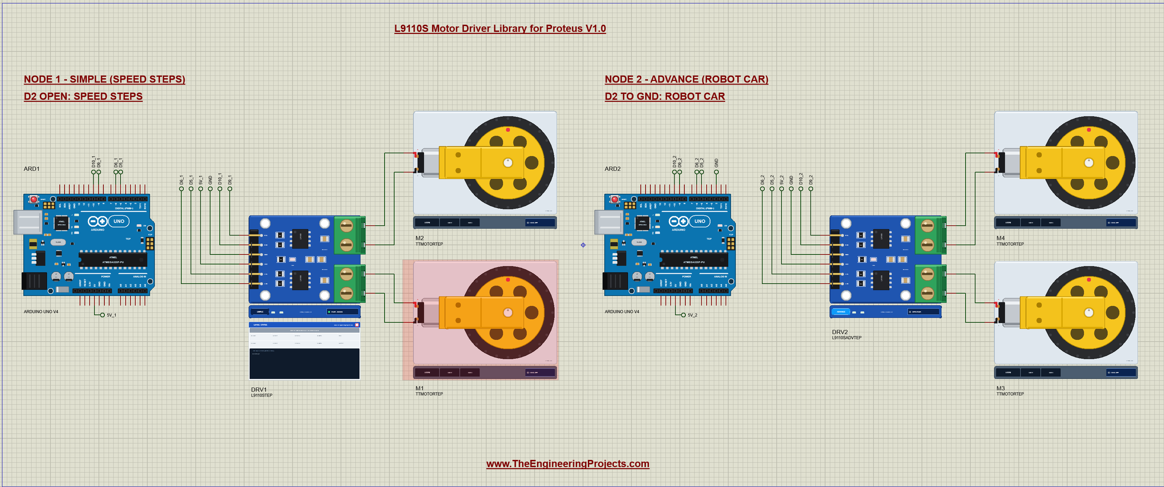
- A two-node demo on our Arduino UNO V4.0: speed steps on one, a robot car on the other.
- A compact package: about 1.41 MB, without the C++ source code.
Three Devices: Simple, Advance and the Motor
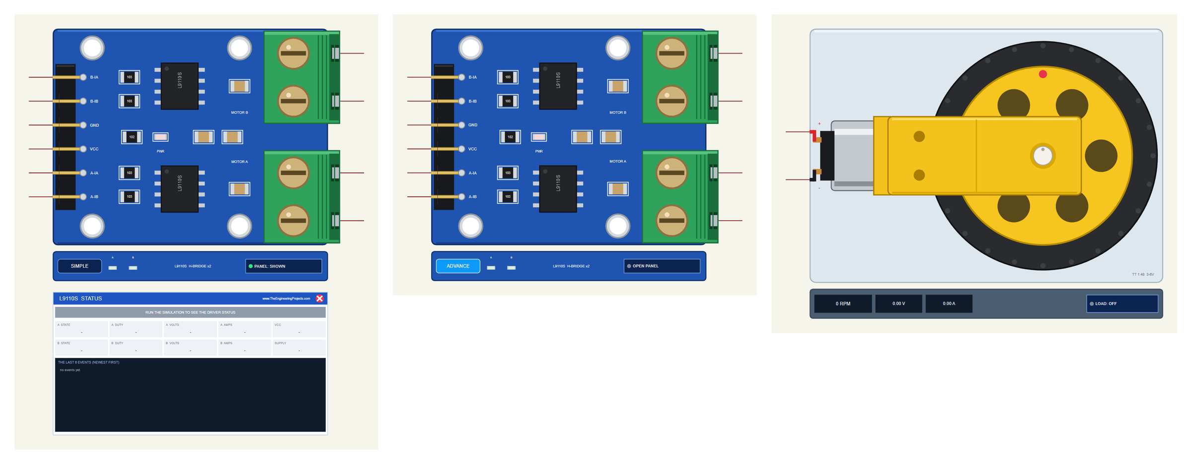
| Simple | Advance | Motor | |
|---|---|---|---|
| Device | L9110STEP | L9110SADVTEP | TTMOTORTEP |
| Library file | TEPL9110S.LIB | TEPL9110S.LIB | TEPMOTOR.LIB |
| On the schematic | The board + the STATUS panel | The board only | The motor with its wheel |
| Status | Banner, 10 readouts, the last 6 events | A pop-up: Motors, Event log, Tests | RPM, volts, amps |
| Interaction | PANEL button | OPEN PANEL button | LOAD button, a click on the wheel |
Download L9110S Motor Driver Library for Proteus
Click the button below to download L9110S-Motor-Driver-Library-for-Proteus-v1.0.zip (about 1.41 MB, without the C++ source code):
L9110S Motor Driver Library for Proteus V1.0- README.txt: the devices, installation, the demo, wiring, the test tools and real hardware.
- Proteus Library Files:
TEPL9110S.LIB,TEPMOTOR.LIBandArduinoV4TEP.LIBfrom our Arduino Library for Proteus V4.0. - Proteus Model Files:
TEPL9110S.DLL,TEPMOTOR.DLLandTEPARDUINO.DLL. - Proteus Simulation:
L9110S-Motor-Driver-ArduinoUnoV4.pdsprj,L9110S_Demo.hexand copies of the three DLLs. - Arduino Code:
L9110S_Demo.ino(no library needed).
No Proteus yet? Read How to Download and Install Proteus 7 and 8. New to libraries? Follow How to Install a New Library in Proteus.
How to Install L9110S Motor Driver Library for Proteus
- Close Proteus and extract the whole zip file, for example to your Desktop.
- Copy the three files from Proteus Library Files into the LIBRARY folder of Proteus (usually
C:\Program Files (x86)\Labcenter Electronics\Proteus 8 Professional\LIBRARY). - Copy
TEPL9110S.DLL,TEPMOTOR.DLLandTEPARDUINO.DLLfrom Proteus Model Files into the MODELS folder. - Delete
TEPL9110S.IDXandTEPMOTOR.IDXfrom the LIBRARY folder if they are there. - Start Proteus, press P and search for L9110S and TT MOTOR.
Tip: keep the Proteus Simulation folder together, because the project needs its .hex file and the DLLs beside it. The library is tested in Proteus 8.5; Proteus 7 is not supported.
The L9110S Module in Proteus
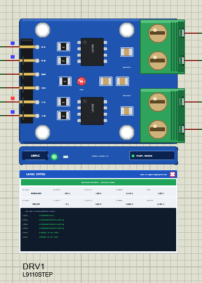
The driver looks like the real HG7881 board, turned by 90 degrees so the inputs come in from the left and the motors leave to the right. On the board you see the two L9110S chips, the four 10k pull-ups marked 103, the 1k resistor marked 102 for the LED, the capacitors and the two green terminals. The red PWR LED D1 lights as soon as the chips have power (VCC above about 2.4 V), just like on the real board.
Under the board is the TEP strip. Its A and B LEDs show each channel: green for forward, red for reverse, brighter with more duty, dark for brake or coast. The strip, its LEDs and the panels are TEP additions; a real module has none of them.
The Simple driver adds the L9110S STATUS panel. Its banner says what both motors do, for example "MOTOR A: FWD 100 %", or shows NO POWER, or the latest warning in red. Ten readouts follow: the state, duty, volts and amps of each channel, VCC and the supply current. At the bottom are the last six events. The red X closes the panel, and the PANEL button on the strip opens it again.
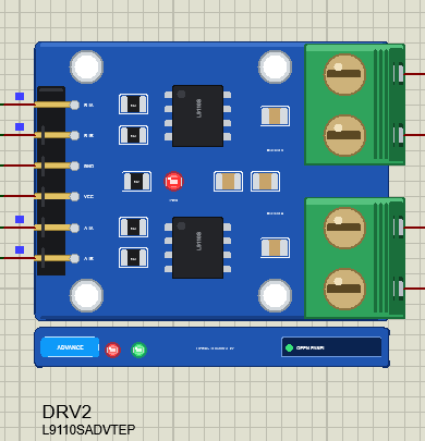
The Advance driver keeps the schematic clean: only the board and its strip. Its live data opens in a pop-up window at Run, and the OPEN PANEL button brings the window back if you close it.
The TT Gear Motor in Proteus
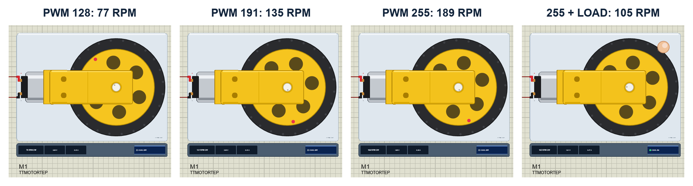
The motor is drawn from the inside of a robot car: the yellow gearbox in front, the silver motor can behind it with its red and black wires, and the wheel with its yellow hub and black tyre on the far shaft. While the simulation runs the wheel turns at the simulated speed, and so does the white shaft stub on the gearbox. When it is fast the spokes get a motion blur, so the wheel never seems to turn backwards on your screen. The red dot on the hub shows the real rotation.
The strip under the motor shows the speed with its direction, for example "189 RPM CW", the voltage across the motor and its current. These are 50 ms averages, so they read calmly even with PWM. With the demo's 5 V the motor reached 77, 135 and 189 RPM at PWM 128, 191 and 255.
The LOAD Button
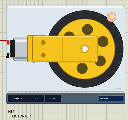
Click LOAD under a motor, or click its wheel, and a finger presses on the tyre. That is 0.2 kg.cm of friction on the wheel. The motor slows down and draws more current, exactly what your sketch and your power supply will meet in a real robot. Click again to lift the finger. The property LOAD adds a constant load in kg.cm for the whole run.
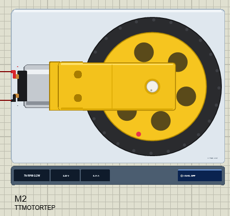
If a motor is held for half a second at more than 0.5 A, it writes STALLED to the simulation log; above 7.5 V it warns about the over-voltage, because the TT motor is rated for 3 - 6 V.
The Demo Circuit
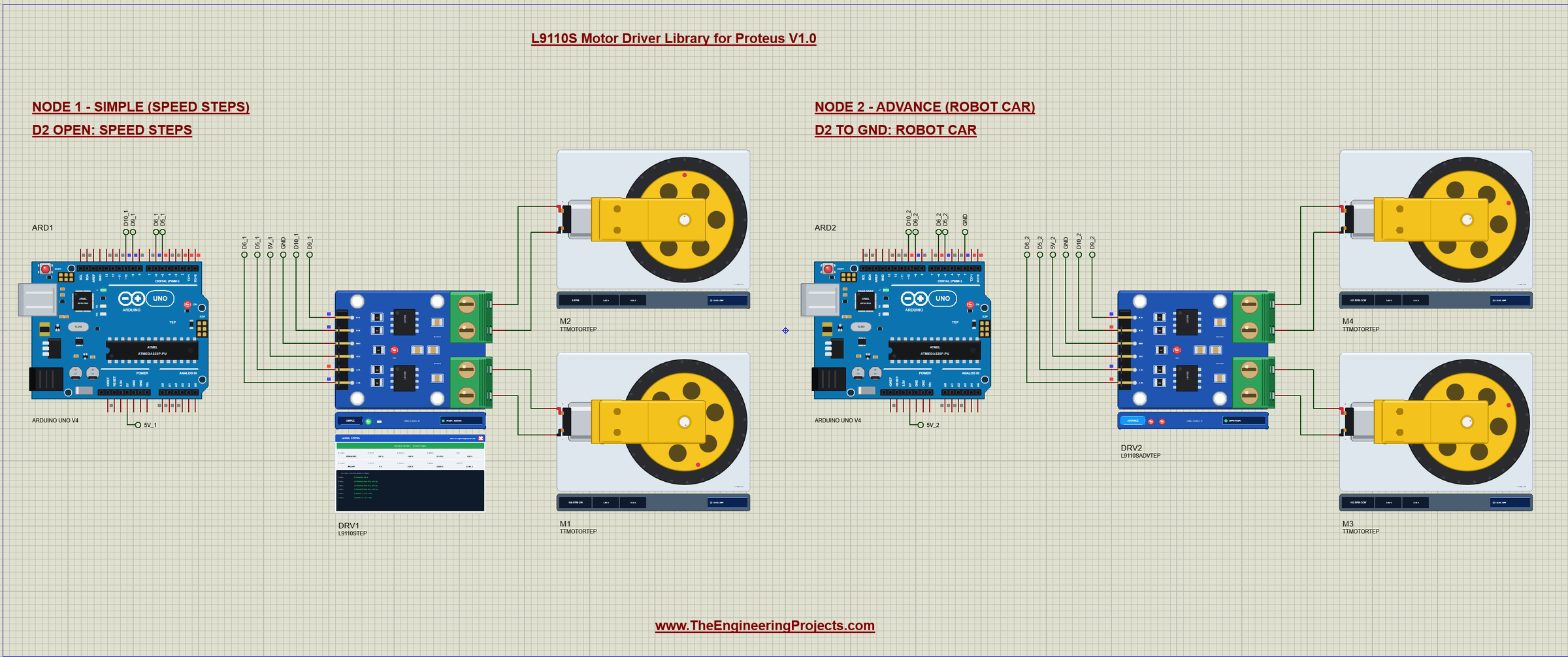
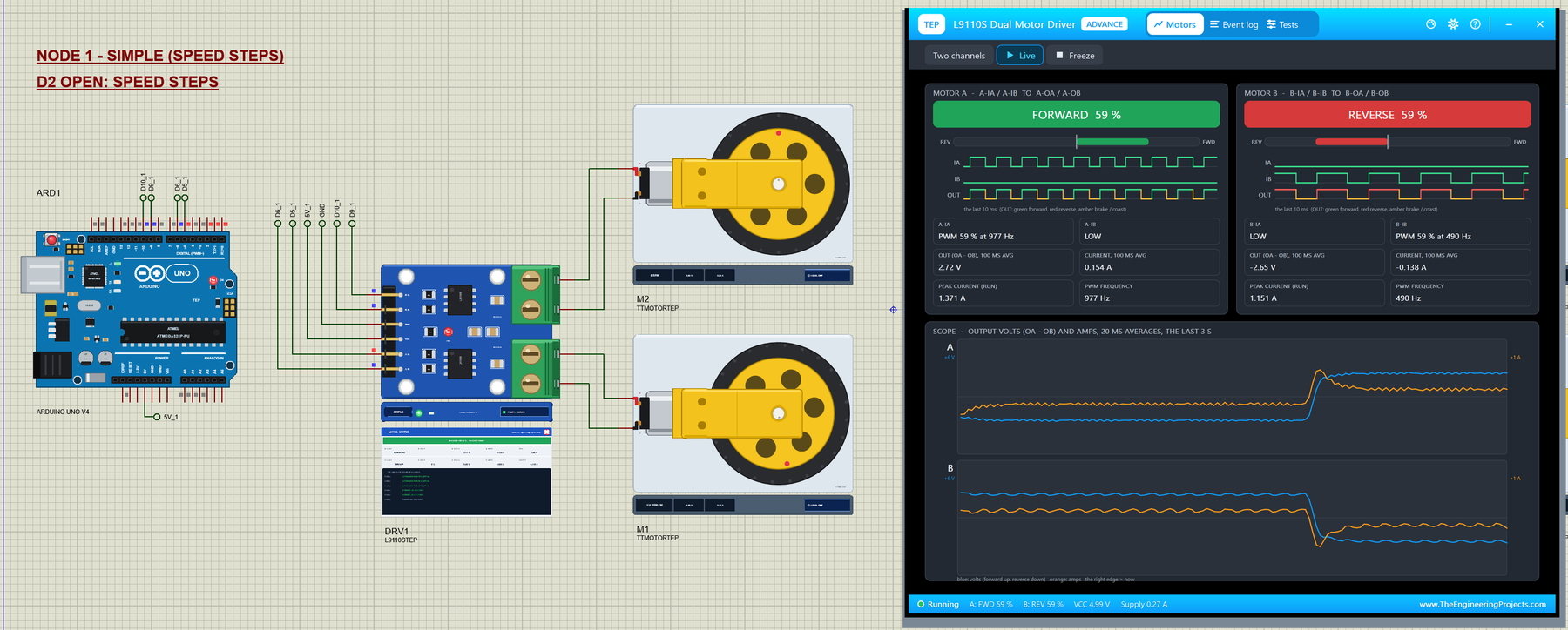
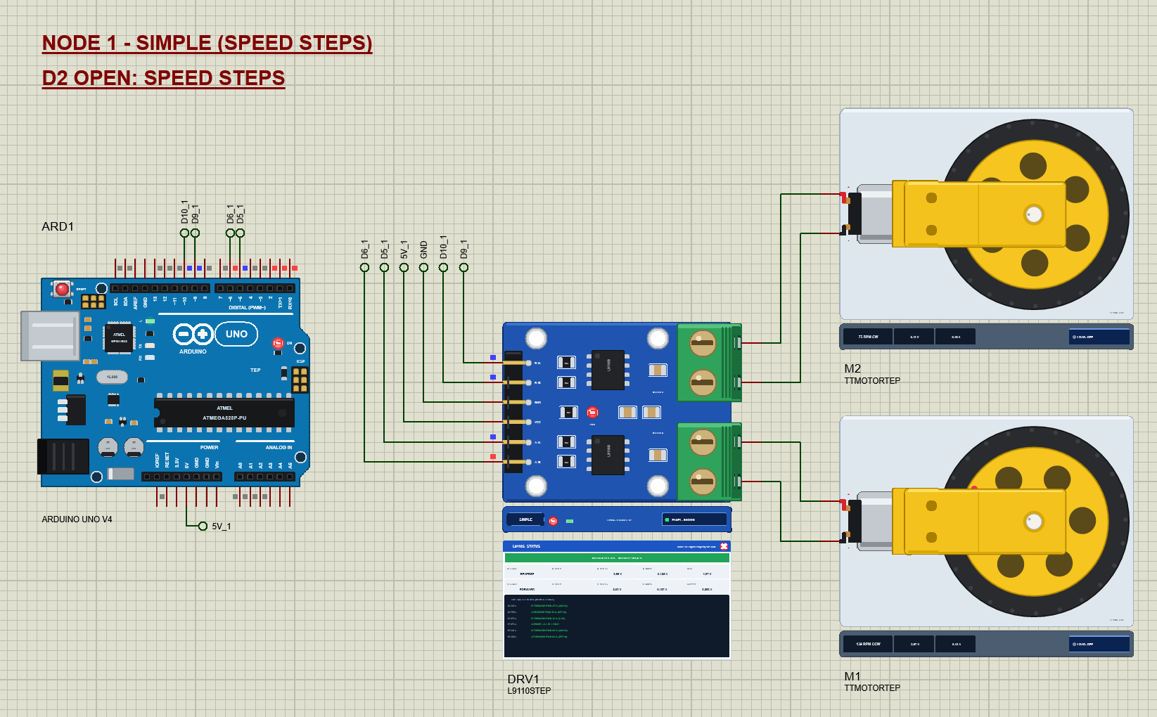
The demo project has two nodes. Each one is an Arduino UNO V4.0 from our Arduino UNO Library for Proteus V4.0, one L9110S driver and two TT motors. Both UNOs run the same L9110S_Demo.hex; the D2 pin chooses the demo. Node 1 leaves D2 open and runs the speed steps on the Simple driver; node 2 ties D2 to GND and drives its Advance driver as a robot car.
Wiring
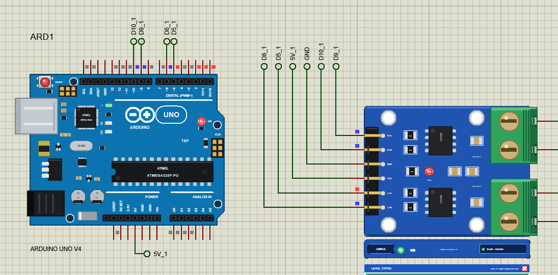
| Module | Arduino UNO | Note |
|---|---|---|
| B-IA | D9 | PWM 490 Hz |
| B-IB | D10 | PWM 490 Hz |
| GND | GND | common with the motor supply |
| VCC | 5V | or a 2.5 - 12 V motor supply |
| A-IA | D5 | PWM 980 Hz |
| A-IB | D6 | PWM 980 Hz |
| MOTOR A | motor A | A-OA to +, A-OB to - |
| MOTOR B | motor B | B-OA to +, B-OB to - |
In Proteus every header pin reaches its UNO through a wire with a net label: D9_1, D10_1, D5_1, D6_1 and 5V_1 for node 1, the same with _2 for node 2, and GND. The motors are wired straight to the terminals, so you can follow each wire from the chip to the motor. The serial monitor needs no wires at all, because it is built into the UNO V4.0.
Node 1: Speed Steps on the Simple Driver
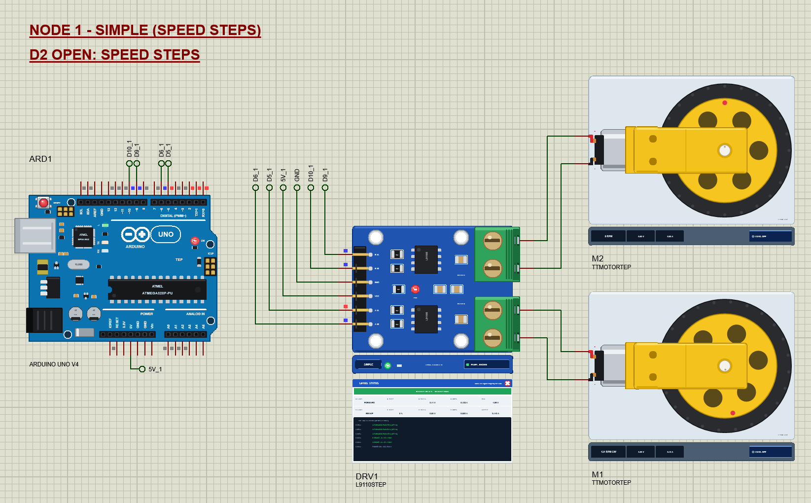
The speed steps run motor A at 25, 50, 75 and 100 %, then motor B in reverse at 50 and 100 %, both at 60 %, a brake with all inputs HIGH, motor A in reverse with motor B forward, and off. Most steps last 2.5 s, and the list starts again.
Node 2: The Robot Car on the Advance Driver
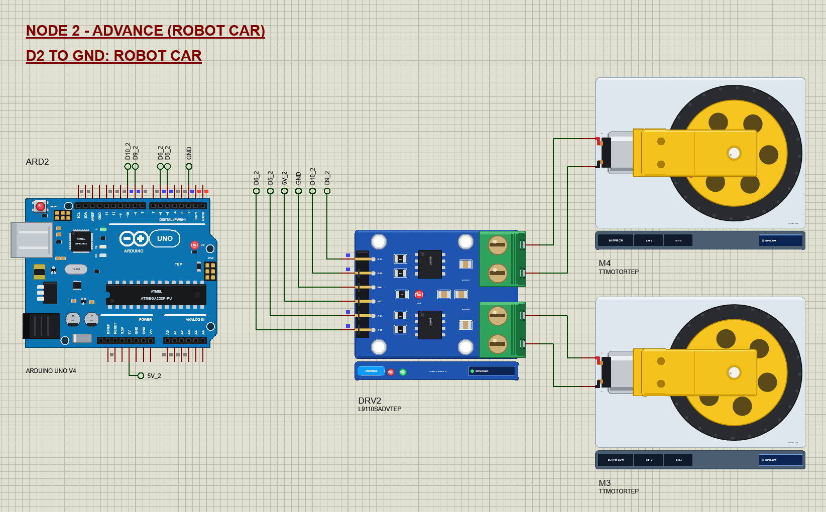
The robot car drives forward at PWM 200, turns left and right by running the motors in opposite directions, drives backward, stops with a brake and creeps forward at PWM 100. A real two-wheel car does exactly this with the same sketch.
The Arduino Code
The demo needs no library: digitalWrite() and analogWrite() are all an L9110S needs. New to Arduino? Start with Arduino Tutorial for Beginners and Introduction to Arduino UNO. The pins come first:
const uint8_t A_IA = 5, A_IB = 6;   // motor A
const uint8_t B_IA = 9, B_IB = 10;  // motor B
const uint8_t MODE_PIN = 2;          // open = speed steps, GND = robot car
The sketch keeps the truth table in one comment at its top:
// The L9110S's truth table: IA HIGH + IB LOW = forward, IA LOW + IB HIGH = reverse, both HIGH = brake (both LOW: brake on most
// boards, coast on some). Speed: PWM on one input while the other is LOW - the off time brakes, so speed follows the duty.
One function turns a signed speed into the two inputs. A positive speed puts PWM on IA with IB LOW, a negative one puts PWM on IB with IA LOW, and zero sets both LOW:
void drive(uint8_t ia, uint8_t ib, int speed) {
  speed = constrain(speed, -255, 255);
  if (speed > 0) { digitalWrite(ib, LOW); analogWrite(ia, speed); }
  else if (speed < 0) { digitalWrite(ia, LOW); analogWrite(ib, -speed); }
  else { digitalWrite(ia, LOW); digitalWrite(ib, LOW); }
}
Note the order: the pin that must be LOW is written first, so the motor never sees both inputs active by accident. Braking sets all four inputs HIGH:
void brakeBoth() {                   // both inputs HIGH: the outputs short the motor - it stops at once
  digitalWrite(A_IA, HIGH); digitalWrite(A_IB, HIGH);
  digitalWrite(B_IA, HIGH); digitalWrite(B_IB, HIGH);
}
void setA(int s) { speedA = constrain(s, -255, 255); drive(A_IA, A_IB, speedA); }
void setB(int s) { speedB = constrain(s, -255, 255); drive(B_IA, B_IB, speedB); }Each speed is printed as a percentage with its PWM value. The percentage is rounded, so PWM 191 prints 75 %:
void printSpeed(char m, int s) {
  Serial.print(m); Serial.print(F(": "));
  if (s > 0) Serial.print(F("FORWARD ")); else if (s < 0) Serial.print(F("REVERSE ")); else { Serial.print(F("OFF (IA = IB = LOW)")); return; }
  Serial.print(((long)abs(s) * 100 + 127) / 255); Serial.print(F(" % (PWM ")); Serial.print(abs(s)); Serial.print(')');
}
The two demos are just tables of steps. Each step holds the speed of motor A, the speed of motor B, how long it lasts and its name; 999 means brake:
struct Step { int a, b; uint16_t ms; const char* name; };const Step CAR[] = {{200, 200, 3000, C0}, {-150, 150, 2000, C1}, {150, -150, 2000, C2}, {-200, -200, 3000, C3}, {999, 999, 1500, C4}, {100, 100, 3000, C5}};In setup() the pins become outputs, both motors start with their inputs LOW, and D2 decides the demo:
void setup() {
  pinMode(A_IA, OUTPUT); pinMode(A_IB, OUTPUT); pinMode(B_IA, OUTPUT); pinMode(B_IB, OUTPUT);
  setA(0); setB(0);
  pinMode(MODE_PIN, INPUT_PULLUP);
  car = digitalRead(MODE_PIN) == LOW;
The commands from the serial monitor are read in loop(). "A" or "B" with a number sets that motor and stops the automatic demo:
void command(char* c) {
  for (char* p = c; *p; ++p) *p = toupper(*p);
  if ((c[0] == 'A' || c[0] == 'B') && (c[1] == ' ' || c[1] == '=')) {
    autoRun = false;
    const int v = atoi(c + 2);
    if (c[0] == 'A') setA(v); else setB(v);
    report(F("SET"));
if (autoRun) {
const Step& s = car ? CAR[step] : STEPS[step];
if (millis() - stepAt >= s.ms) {
step = (step + 1) % (car ? sizeof CAR / sizeof CAR[0] : sizeof STEPS / sizeof STEPS[0]);
runStep();
}
}The HEX file is in the package. To change the sketch, open it in the Arduino IDE and export the compiled binary, as in How to get the HEX file from Arduino. It needs 5,728 bytes of flash and 382 bytes of RAM.
The Advance Pop-Up Window
At Run, the Advance driver opens TEP L9110S Motor Driver Advance, with the look of our TEP Serial Monitor Advance for Proteus. It has three tabs, Motors, Event log and Tests, plus Settings and Help behind the gear and question mark icons.
Motors
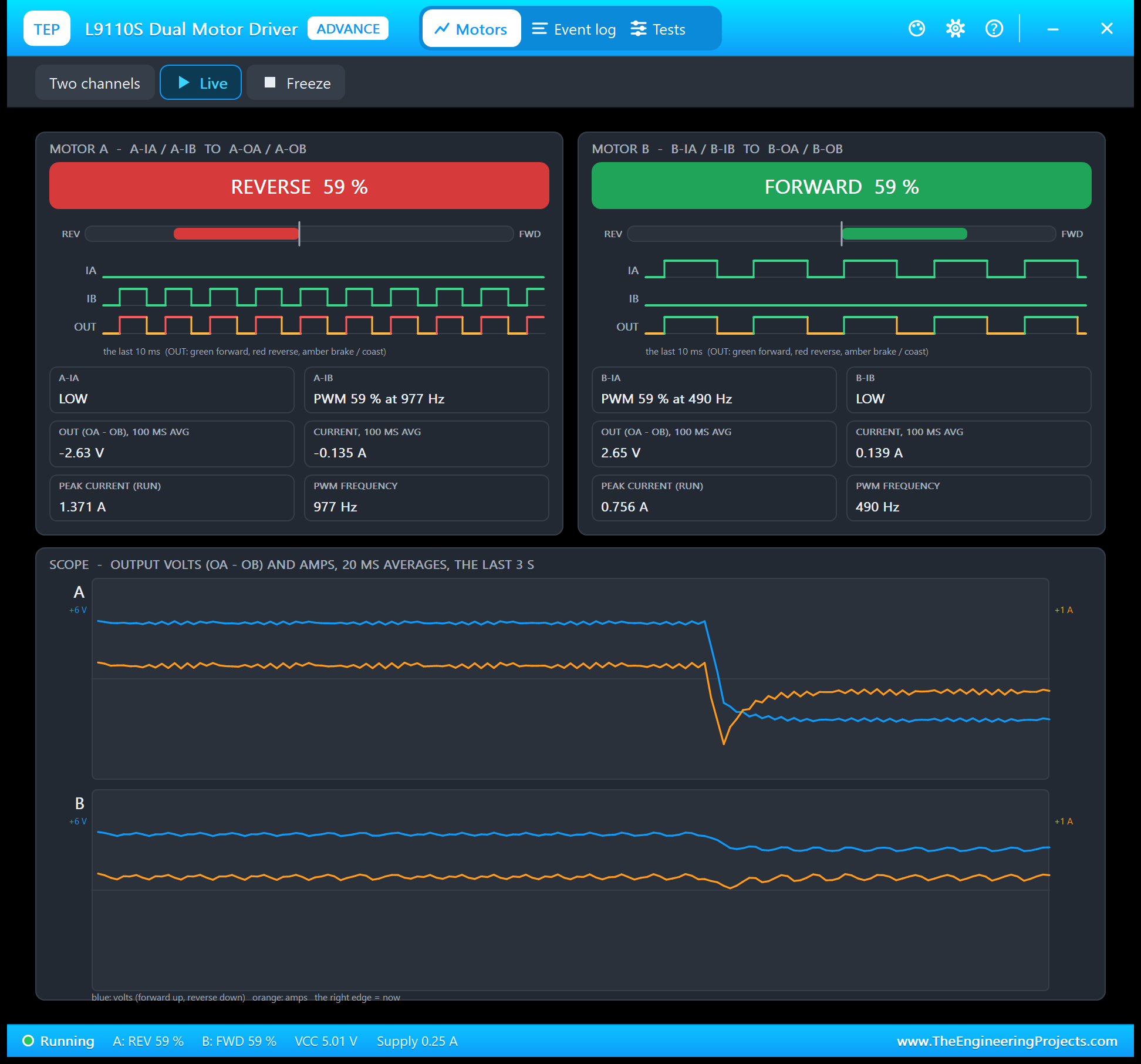
Each motor gets a card. The big coloured bar names the drive and its duty, green for forward and red for reverse. The gauge below it runs from full reverse to full forward. Then come IA, IB and the output over the last 10 ms as waveforms, so you see the PWM pulses the sketch sends, and the output turns amber whenever the motor is braked. The tiles give each input's PWM, the output volts and amps as 100 ms averages, the peak current of the run and the PWM frequency.
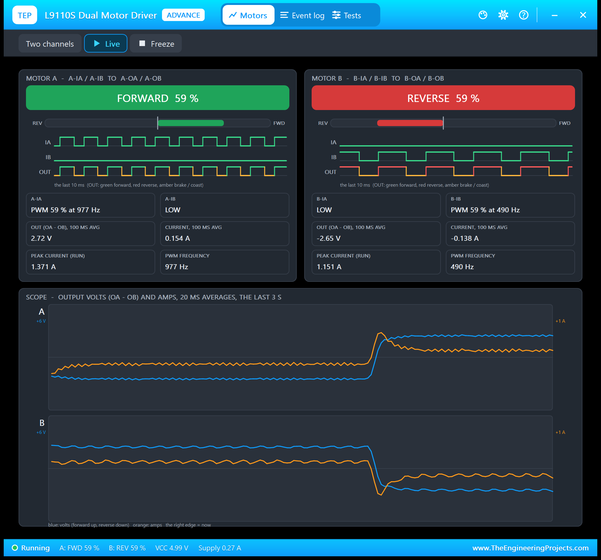
The scope at the bottom draws the output volts (blue) and amps (orange) of both channels over the last 3 s. Watch the moment a motor reverses: the current jumps while the motor is still turning the wrong way, then settles. That peak, 1.37 A in this run, is why a real driver gets hot when you reverse at full speed. Freeze holds the page for a closer look.
Event Log
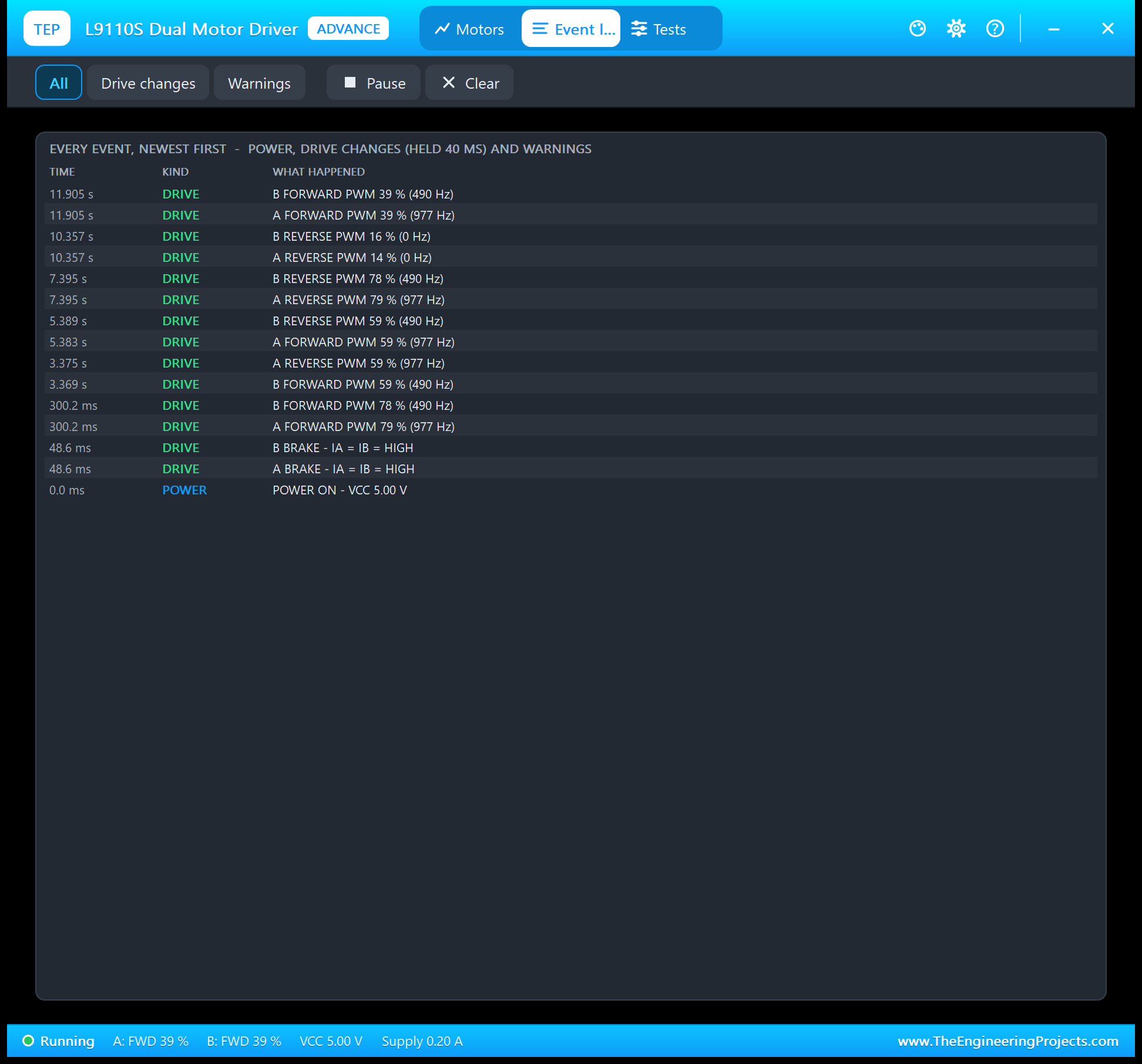
The Event log lists power on and off, every drive change that held for 40 ms, for example "A FORWARD PWM 79 % (977 Hz)", and the warnings. Filter it by drive changes or warnings, pause it, or clear it. Notice 79 % for PWM 200 on motor A but 78 % on motor B: the 980 Hz pins of the UNO use a different timer mode than the 490 Hz pins, and the model measures the real pulses.
The Test Tools
The Tests tab holds three tools. Each one reads the driver as the model sees it and gives every row a green, amber or red verdict.
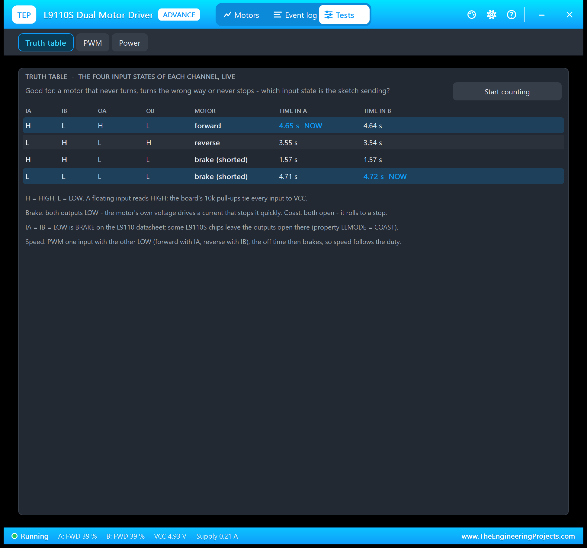
Truth table is good for a motor that never turns, turns the wrong way or never stops. It shows the four input states with OA, OB and what the motor does, highlights the state each channel is in right now, and counts the seconds each channel spent in each state. If the sketch never reaches the forward row, you know where to look.
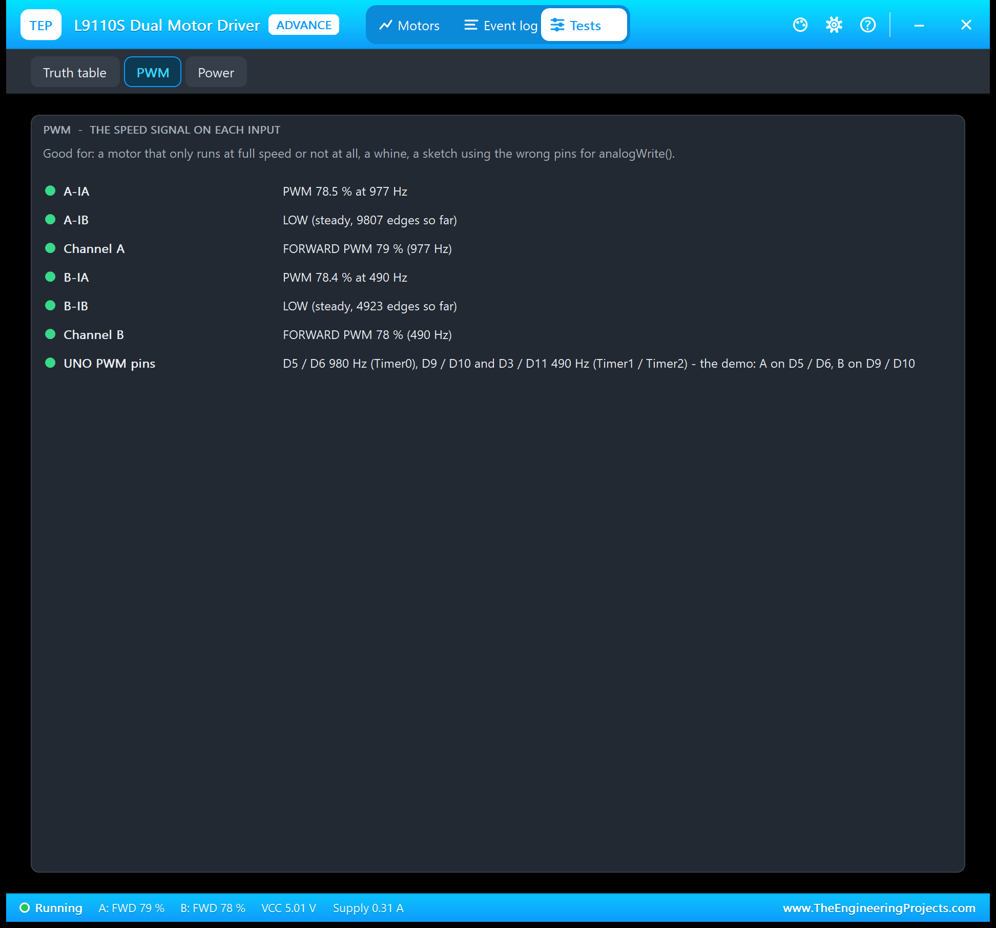
PWM is good for a motor that only runs at full speed or not at all, or a sketch that uses a pin without PWM. Every input shows its duty and frequency or a steady HIGH or LOW, and the tool warns about PWM slower than 100 Hz or faster than the chip can switch.
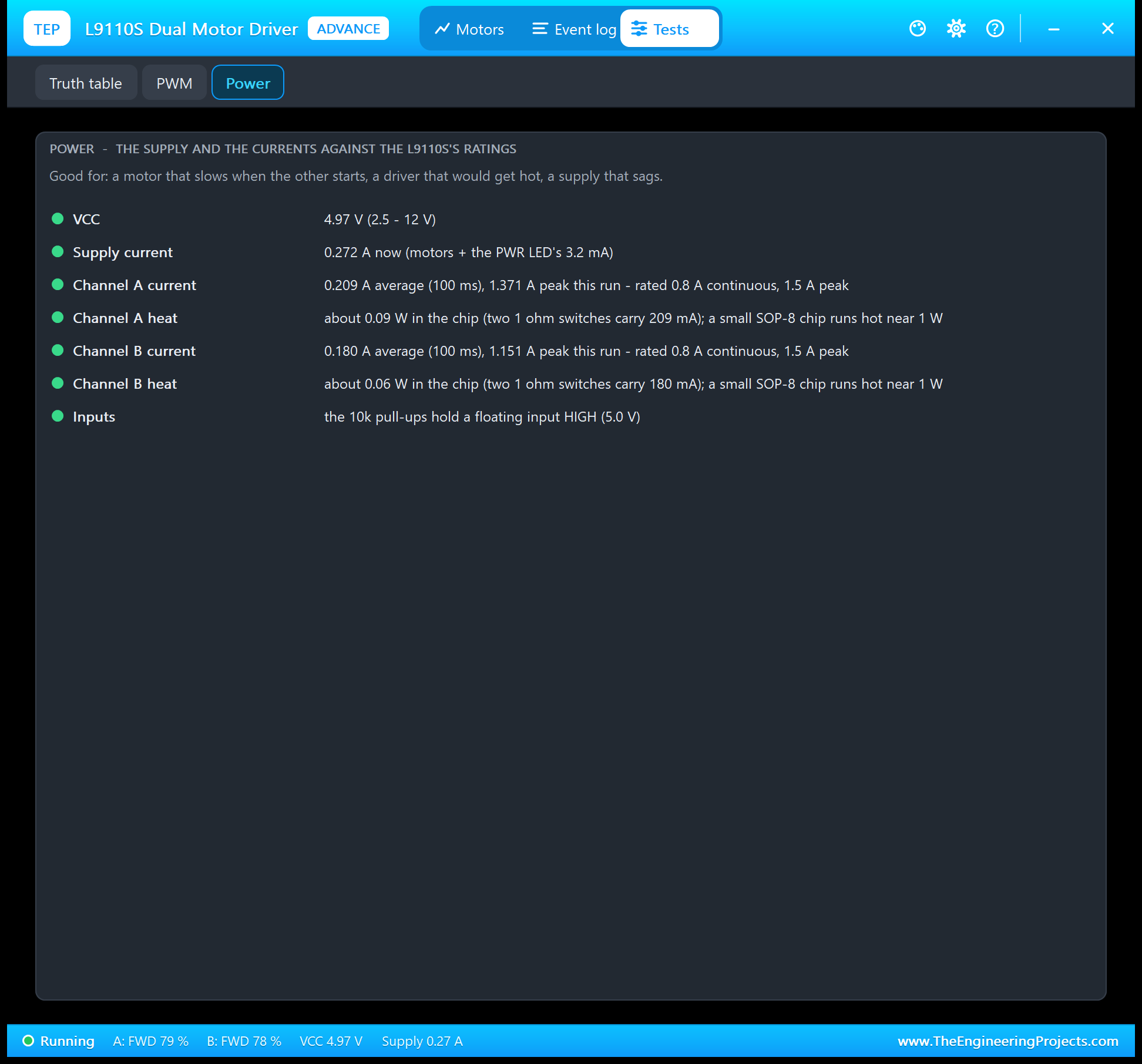
Power is good for a motor that slows when the other one starts, or a driver that would get hot. It shows VCC, the supply current, each channel's average and peak current against the 0.8 A and 1.5 A ratings, the power lost in the chip and a note about the pull-ups.
The Serial Monitor
Both UNOs have the serial monitor built in, and it opens at Run. The screenshots use its Simple interface. Node 1 starts like this:
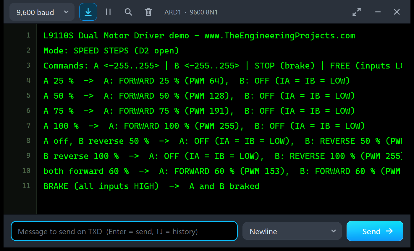
L9110S Dual Motor Driver demo - www.TheEngineeringProjects.com
Mode: SPEED STEPS (D2 open)
Then every step prints its name and what both motors get:
| The step | What the motors get |
|---|---|
| A 25 % | A: FORWARD 25 % (PWM 64), B: OFF (IA = IB = LOW) |
| A 75 % | A: FORWARD 75 % (PWM 191), B: OFF (IA = IB = LOW) |
| both forward 60 % | A: FORWARD 60 % (PWM 153), B: FORWARD 60 % (PWM 153) |
| BRAKE (all inputs HIGH) | A and B braked |
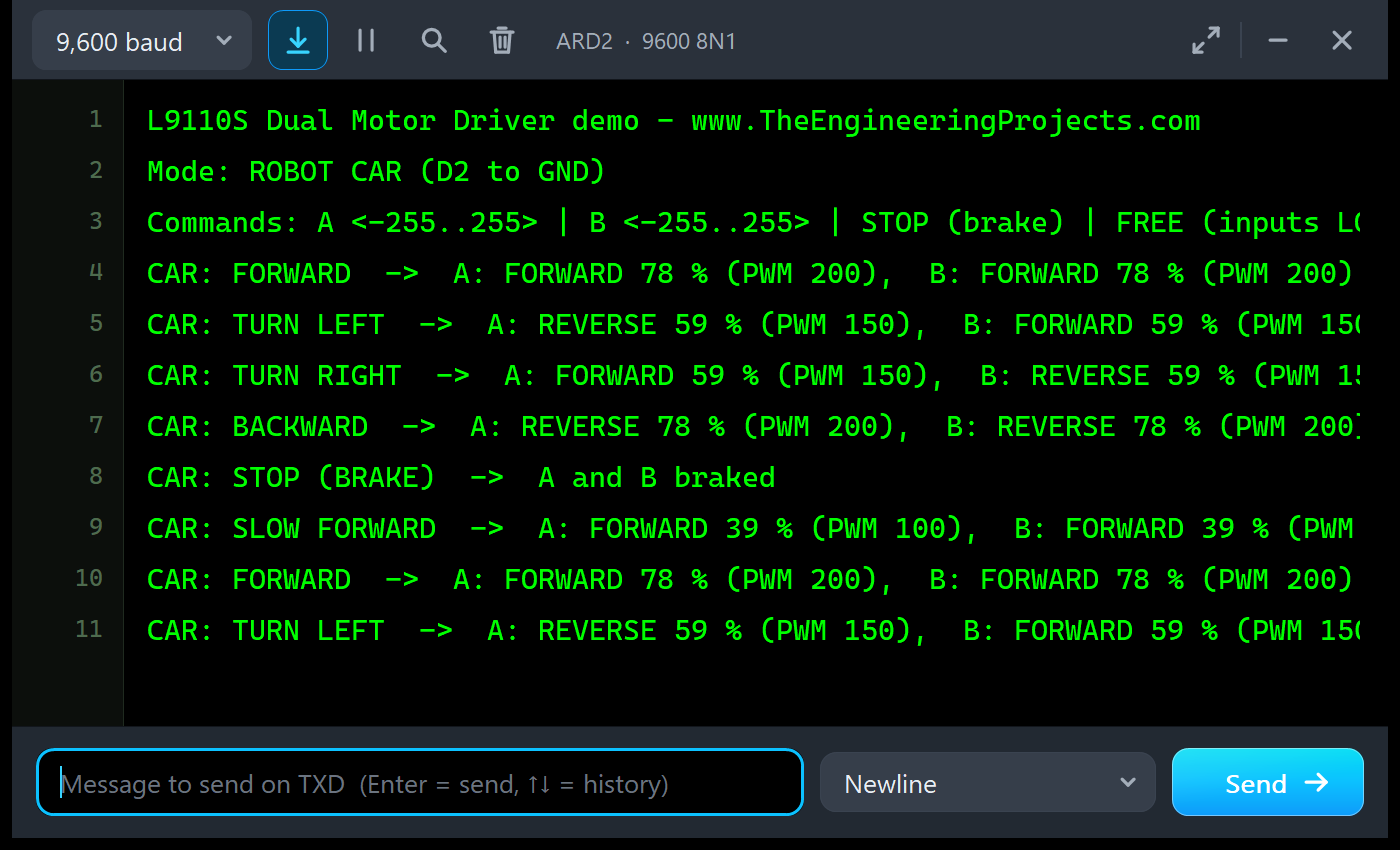
L9110S Dual Motor Driver demo - www.TheEngineeringProjects.com
Mode: ROBOT CAR (D2 to GND)| The move | What the motors get |
|---|---|
| CAR: FORWARD | A: FORWARD 78 % (PWM 200), B: FORWARD 78 % (PWM 200) |
| CAR: TURN LEFT | A: REVERSE 59 % (PWM 150), B: FORWARD 59 % (PWM 150) |
| CAR: BACKWARD | A: REVERSE 78 % (PWM 200), B: REVERSE 78 % (PWM 200) |
| CAR: STOP (BRAKE) | A and B braked |
Commands
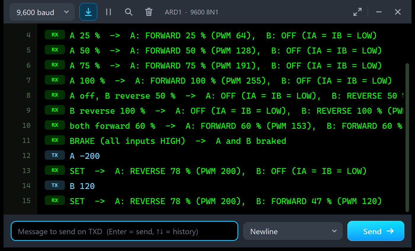
Type a command in the monitor and press Enter. A 150 or A -200 sets motor A, B ... motor B, STOP brakes both, FREE sets all inputs LOW, RUN starts the demo again and HELP lists them. In the run above, A -200 answered "A: REVERSE 78 % (PWM 200)" and B 120 "B: FORWARD 47 % (PWM 120)".
The Simulation Log
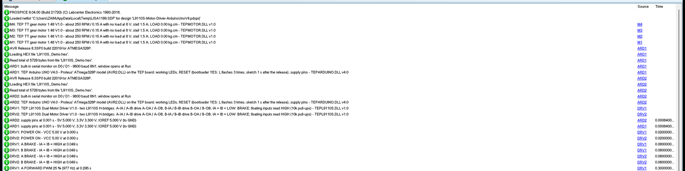
Each driver writes its power-up and every drive change to the simulation log, so a long run leaves a readable story of what the motors did. After 60 drive changes it stops and points to the Event log, which keeps them all.
How the Simulation Handles PWM
Proteus solves the analog part of a circuit in time steps, here at most 2 ms long, and it solves each step before it runs the digital part up to that time. So the driver learns about a PWM edge only after the step that contains it. The model therefore feeds each step with the average of the inputs over it and carries any difference into the next step. The motors follow the PWM one step late, but the time integral of the drive, which is what turns the motor, is exact. On a PC we checked it against exact switching at 980 and 490 Hz: the speeds agree within 4 %.
One consequence: the volts and amps you see are averages, not single PWM pulses. A real motor also smooths the pulses with its inductance and its inertia, so the average is what matters for its speed.
Troubleshooting
- The motors never turn and D1 is dark: no power - check VCC and GND; the L9110S needs at least 2.5 V.
- A motor stays braked: its IA and IB are not connected (the pull-ups read HIGH) or the sketch never writes them; check the Truth table tool.
- Full speed or nothing: the sketch uses a pin without PWM, or only writes 0 and 255; check the PWM tool.
- The motor turns the wrong way: swap its two wires, or swap forward and reverse in the sketch.
- OVER 800 mA or PEAK warnings: a stalled or heavily loaded motor, or a reversal at full speed.
- No part, no wheels or no monitor: TEPL9110S.DLL, TEPMOTOR.DLL or TEPARDUINO.DLL is missing from MODELS and the project folder; a closed monitor opens again with a click on the UNO's USB port.
Things to Know Before Using a Real L9110S Module
- Power: feed the motors from their own supply on VCC, with GND common to the Arduino. TT motors draw up to 1.5 A when they start or stall, more than an Arduino's 5V pin should give.
- Pull-ups: the 10k pull-ups tie the inputs to VCC; above 5 V they lift a floating input above 5 V, which is fine for 5 V Arduino pins but not for 3.3 V boards.
- PWM pins: D5 and D6 give 980 Hz, D3, D9, D10 and D11 give 490 Hz.
- Reversing: brake or slow down before you reverse a fast motor; the current peak is hard on the chip.
- The voltage drop: about 1 V is lost in the chip at 500 mA, so a 6 V motor needs a supply a little above 6 V for its full speed.
Limitations of the Simulation
- The outputs follow PWM one SPICE step (up to 2 ms) late and show averages; single pulses are not resolved.
- Not modelled: the chip's heating and thermal shutdown, the input thresholds below 3 V, the motor's inductance and current ripple, gearbox backlash, a stepper motor, and damage from over-voltage or over-current (the model warns).
- The strip, its LEDs, the panels and the LOAD button are TEP additions.
- The models are our own, written from the L9110 and L9110S datasheets, the board's schematic and the published TT motor data; this library is not made or endorsed by the makers of the chips or the board, or by Labcenter.
- Licences: the demo needs no library; the HEX file contains the Arduino AVR core 1.8.6 with LGPL-licensed code, and the sketch is included.
- Tested in Proteus 8.5 in October 2026 (the demo as shipped on two Arduino UNO V4.0 boards with their built-in monitors: the speed steps, the robot car, the LOAD button, the commands, the pop-up and the three tools; about 0.37 x real time with the pop-up and both monitors open). Proteus 7 is not supported.
So, that was all about the L9110S Motor Driver Library for Proteus V1.0. I hope the truth table, PWM speed control, braking and the behaviour of a real TT motor are clear now, so your robot car drives straight from its first run. If you use the L9110S Motor Driver Library for Proteus in a project, please share it in the comments or in our forum, and if you have any questions, ask in the comments and I will help you out. Till the next tutorial, take care and have fun!
Comments
0