


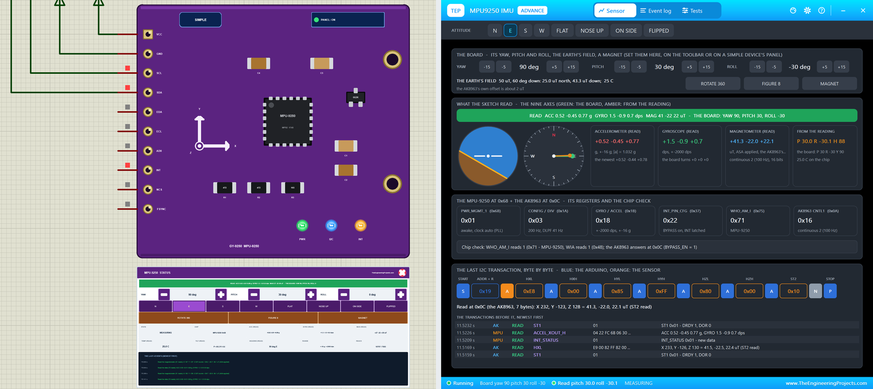
MPU9250 Library for Proteus V1.0: GY-9250 9-Axis IMU for Arduino


Hello friends, I hope you all are doing great. Today, I am going to share the new MPU9250 Library for Proteus V1.0. The MPU-9250 is the 9-axis motion sensor on the purple GY-9250 module: a 3-axis accelerometer, a 3-axis gyroscope and a 3-axis magnetometer in one small package. Drones, self-balancing robots, gimbals and head trackers use it to know their roll, pitch and yaw. Now you can build and test those projects in Proteus.
Behind the part sits our own model, not a part that shows three angles. The MPU-9250 answers the Arduino exactly as its register map says: the sample rate, the ranges, the offset registers, the FIFO and the INT pin, and the AK8963 magnetometer hidden behind the I2C bypass. You turn the board in 15 degree steps, rotate it, wave it in a figure eight or put a magnet on it, and the gyro sees every turn. You get two devices: a Simple device with a live STATUS panel and the board's controls, and an Advance device with a pop-up window and the test tools. The demo runs the MPU9250 library by hideakitai with its Madgwick filter on our Arduino UNO V4.0.
NOTICE: an IMU is easy to fake: hand the Arduino three angles from a property. We wanted more. Our MPU-9250 turns the board's attitude into gravity, rotation and the Earth's field on each chip's own axes, in each chip's own registers, so the hideakitai library and its Madgwick filter work out the angles exactly as on your desk, and a missing magnetometer, a slow loop or a magnet next to the board fails exactly as it does there. It took our team a lot of hard work. Your feedback is the fuel that keeps us going, so please tell us what you think in the comments below or in the MPU9250 board of our forum. And if our free libraries help you, you can buy us a coffee. So, let's get started with the MPU9250 Library for Proteus V1.0:
What is the MPU9250?
The MPU-9250 from InvenSense (now TDK) is a 9-axis motion sensor: inside one package sit an MPU-6500, with a 3-axis accelerometer and a 3-axis gyroscope, and the AK8963 3-axis magnetometer from AKM. The accelerometer feels gravity, so it knows how the board is tilted. The gyroscope measures how fast the board turns. The magnetometer feels the Earth's field, so it knows where north is. For a 6-axis sensor, see our Introduction to MPU6050 and our MPU6050 Library for Proteus; another inertial module is the LSM6DSL iNEMO inertial module. If you need only one of the three, try our ADXL345 Accelerometer Library for Proteus or our HMC5883L / QMC5883L Compass Library for Proteus. The GY-9250 module adds a 3.3 V regulator and the I2C pull-ups, so it works from 5 V too.
| MPU-9250 | |
|---|---|
| Accelerometer | +-2, +-4, +-8 or +-16 g (16384 to 2048 counts a g) |
| Gyroscope | +-250, +-500, +-1000 or +-2000 dps (131 to 16.4 counts a dps) |
| Magnetometer | the AK8963: 14 bits (0.6 uT a count) or 16 bits (0.15 uT a count), 8 or 100 Hz |
| I2C addresses | the MPU at 0x68 (AD0 low) or 0x69 (AD0 high); the AK8963 at 0x0C behind the bypass |
| Identity | WHO_AM_I (0x75) = 0x71; the AK8963's WIA = 0x48 |
| Extras | a 512-byte FIFO, an INT pin, offset registers, self-test, wake on motion, a thermometer |
| Devices | MPU9250TEP (Simple) and MPU9250ADVTEP (Advance) |
The Magnetometer Behind the Bypass
The AK8963 does not sit on the Arduino's bus. It hangs on the MPU's own auxiliary I2C bus, and the Arduino reaches it in one of two ways: set BYPASS_EN in INT_PIN_CFG (0x37), and the AK8963 appears at 0x0C on the main bus; or let the MPU's own I2C master read it into the EXT_SENS_DATA registers. The hideakitai library uses the bypass. Its data comes low byte first, its X and Y axes are the MPU's Y and X, and a read must end with the ST2 register, or the chip keeps its old data. Each chip also stores three sensitivity adjustments (ASA) in a fuse ROM, which the sketch reads once.
MPU-9250 or MPU-6500? The Classic Trap
The MPU-9250 has been out of production for years, and many boards sold as GY-9250 carry an MPU-6500 instead: the same accelerometer and gyroscope, but no magnetometer. WHO_AM_I reads 0x70 instead of 0x71, the hideakitai library's setup() fails at the AK8963 (with its verbose mode on, it prints "Could not connect to AK8963"), and there is no yaw. The chip itself tells you: MP92 on an MPU-9250, MP65 on an MPU-6500. The model's CHIP property switches it, so you can see this trap in Proteus.
From Nine Numbers to Roll, Pitch and Yaw
With the board still, the accelerometer gives the pitch and the roll from gravity. The gyroscope is fast and smooth, but its small bias makes any angle it integrates drift. The magnetometer gives the heading, once it is turned level with the pitch and the roll. A Madgwick filter mixes all three into one attitude, and that is what the hideakitai library does in update(). Two things pull the yaw off: a magnet or steel on the board (hard iron, removed by turning the board through every direction) and the declination, the angle between magnetic and true north. The library starts with -7.51 degrees, the value for Japan, so set yours.
What's New in MPU9250 Library for Proteus V1.0
- The real module: the purple GY-9250 with the MPU-9250, its regulator, the pull-ups and the X / Y / Z marks, drawn at about three times its real size, with the header VCC, GND, SCL, SDA, EDA, ECL, AD0, INT, NCS and FSYNC.
- Two styles: a Simple device with a STATUS panel and an Advance device with a pop-up window; the PWR, I2C and INT LEDs and the panel button sit on the board itself.
- The real MPU-9250: the sample rate and the DLPF, the four accelerometer and four gyro ranges, cycle mode, the offset registers, self-test, the FIFO, INT_STATUS and the INT pin, wake on motion, the internal I2C master.
- The real AK8963: behind the bypass at 0x0C, power-down, single and continuous modes, 14 and 16 bits, DRDY, DOR, the data protection until ST2, the fuse ROM and self-test.
- The board on the panel: yaw, pitch and roll in 15 degree steps, eight attitudes from N to FLIPPED, and three actions: ROTATE 360, FIGURE 8 and MAGNET. Every turn is smooth, so the gyro sees it.
- The classic traps: an MPU-6500 sold as an MPU-9250, 0x0C called before BYPASS_EN, the other MPU address, and a loop too slow for the 100 Hz magnetometer.
- Four test tools on the Advance device: I2C, Readings, Attitude & calibration, and Registers.
- A two-node demo on our Arduino UNO V4.0 with the hideakitai library: RAW, CALIB, CALMAG, DECL and WHO.
- A compact package: about 1.35 MB, without the C++ source code of the model.
Two Devices: Simple and Advance

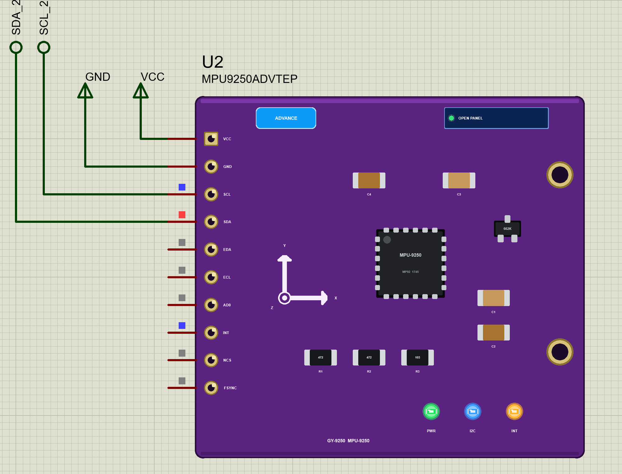
The module carries the MPU-9250 in the middle, marked MP92, the 662K regulator, the pull-ups R1 and R2 (472, 4.7 kohm), R3 on AD0, the capacitors and the axis marks: X to the right, Y up and Z out of the board. The header on the left has all ten pins of the real GY-9250.
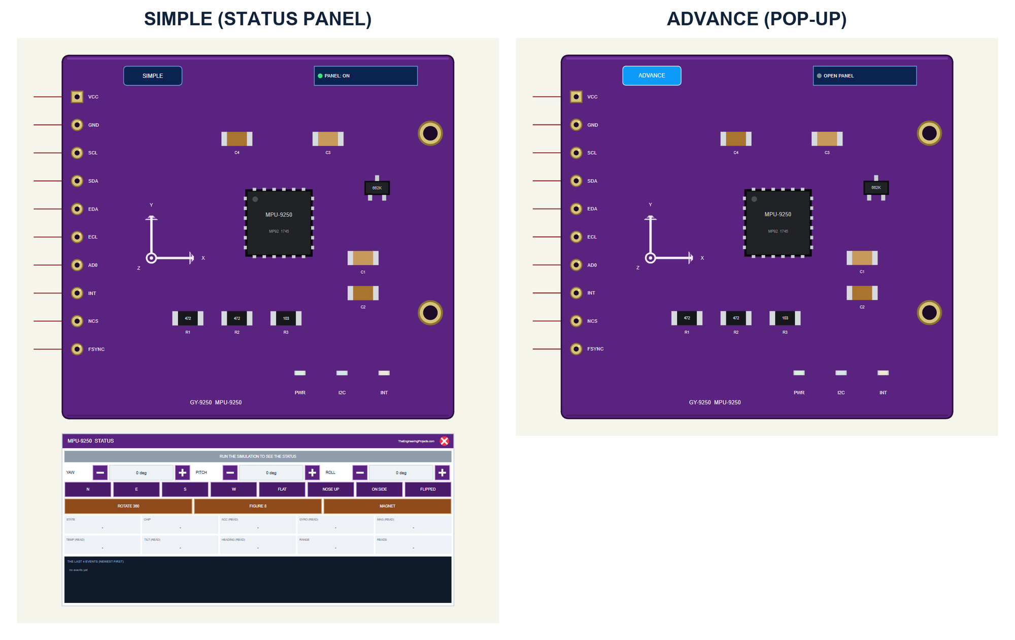
| Simple | Advance | |
|---|---|---|
| Device | MPU9250TEP | MPU9250ADVTEP |
| On the schematic | The module and the STATUS panel | The module |
| The board's attitude and actions | On the STATUS panel | In the pop-up |
| Status | Banner, 10 readouts, the last 4 events | A pop-up: Sensor, Event log, Tests |
Download MPU9250 Library for Proteus
Click the button below to download MPU9250-Library-for-Proteus-v1.0.zip (about 1.35 MB, without the C++ source code of the model):
MPU9250 Library for Proteus V1.0: GY-9250 9-Axis IMU for Arduino- README.txt: the devices, installation, the demo, wiring, the test tools and real hardware.
- Proteus Library Files:
TEPMPU9250.LIBandArduinoV4TEP.LIBfrom our Arduino Library for Proteus V4.0. - Proteus Model Files:
TEPMPU9250.DLLandTEPARDUINO.DLL. - Proteus Simulation:
GY-9250-MPU9250-ArduinoUnoV4.pdsprj,GY9250_IMU_Demo.hexand copies of the two DLLs. - Arduino Code:
GY9250_IMU_Demo.ino. It needs the MPU9250 library by hideakitai from the Library Manager of the Arduino IDE, only if you want to change the sketch.
No Proteus yet? Read How to Download and Install Proteus 7 and 8. New to libraries? Follow How to Install a New Library in Proteus.
How to Install MPU9250 Library for Proteus
- Close Proteus and extract the whole zip file, for example to your Desktop.
- Copy the two files from Proteus Library Files into the LIBRARY folder of Proteus (usually
C:\Program Files (x86)\Labcenter Electronics\Proteus 8 Professional\LIBRARY). - Copy
TEPMPU9250.DLLandTEPARDUINO.DLLfrom Proteus Model Files into the MODELS folder. - Delete
TEPMPU9250.IDXfrom the LIBRARY folder if it is there. - Start Proteus, press P and search for MPU9250.
Tip: keep the Proteus Simulation folder together, because the project needs its .hex file and the DLLs beside it. The library is tested in Proteus 8.5; Proteus 7 is not supported.
The GY-9250 Parts in Proteus
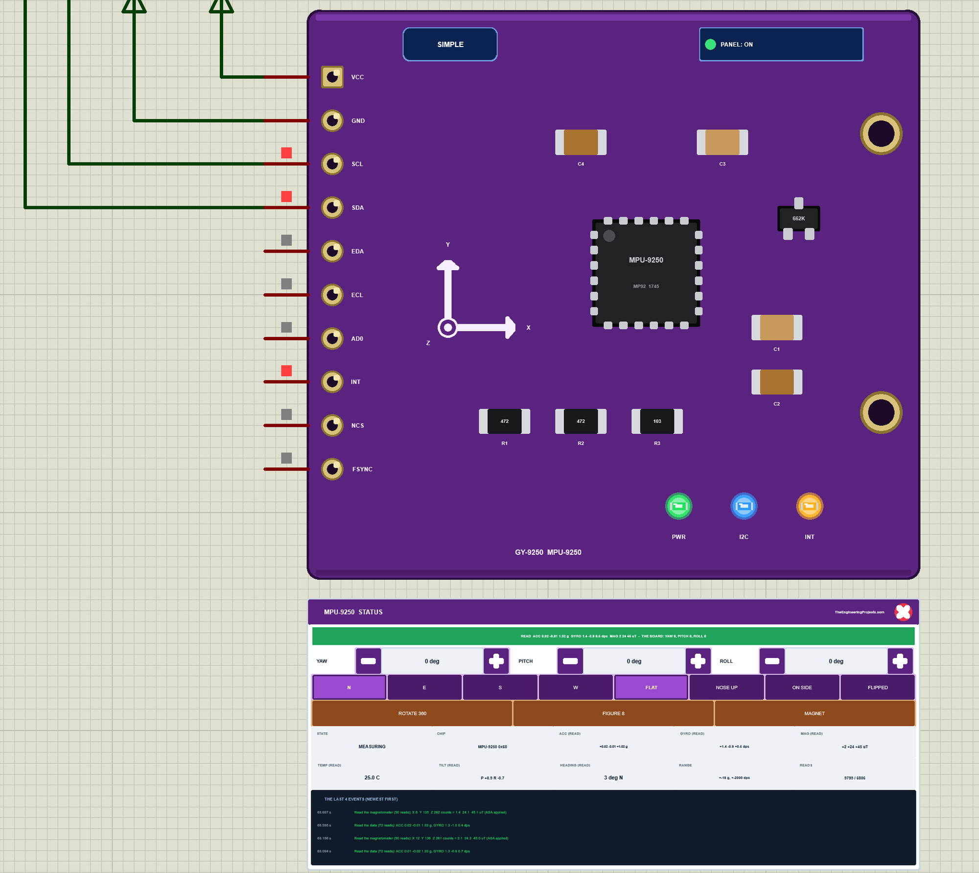
Three LEDs sit on the module's board: PWR while VCC is there, I2C, which flashes when the Arduino talks to the module, and INT, which follows the MPU's INT pin. Next to the SIMPLE or ADVANCE badge is the panel button. The LEDs, the badge, the button and the panels are TEP additions; the real module has none of them.
The Simple device adds the STATUS panel. Its banner shows what the sketch read from all three sensors next to the board's real attitude; it turns amber while the board turns and red for a trap or a warning. Below it are the board's controls: YAW, PITCH and ROLL with - and + (15 degrees a click), eight attitudes (N, E, S, W, FLAT, NOSE UP, ON SIDE and FLIPPED) and three actions: ROTATE 360, FIGURE 8 and MAGNET. Ten readouts follow - the state, the chip, the accelerometer, the gyro and the magnetometer as read, the temperature, the tilt and the heading from the reading, the ranges and the reads - and the last four events.
The red X closes the STATUS panel, and the PANEL button on the board opens it again:
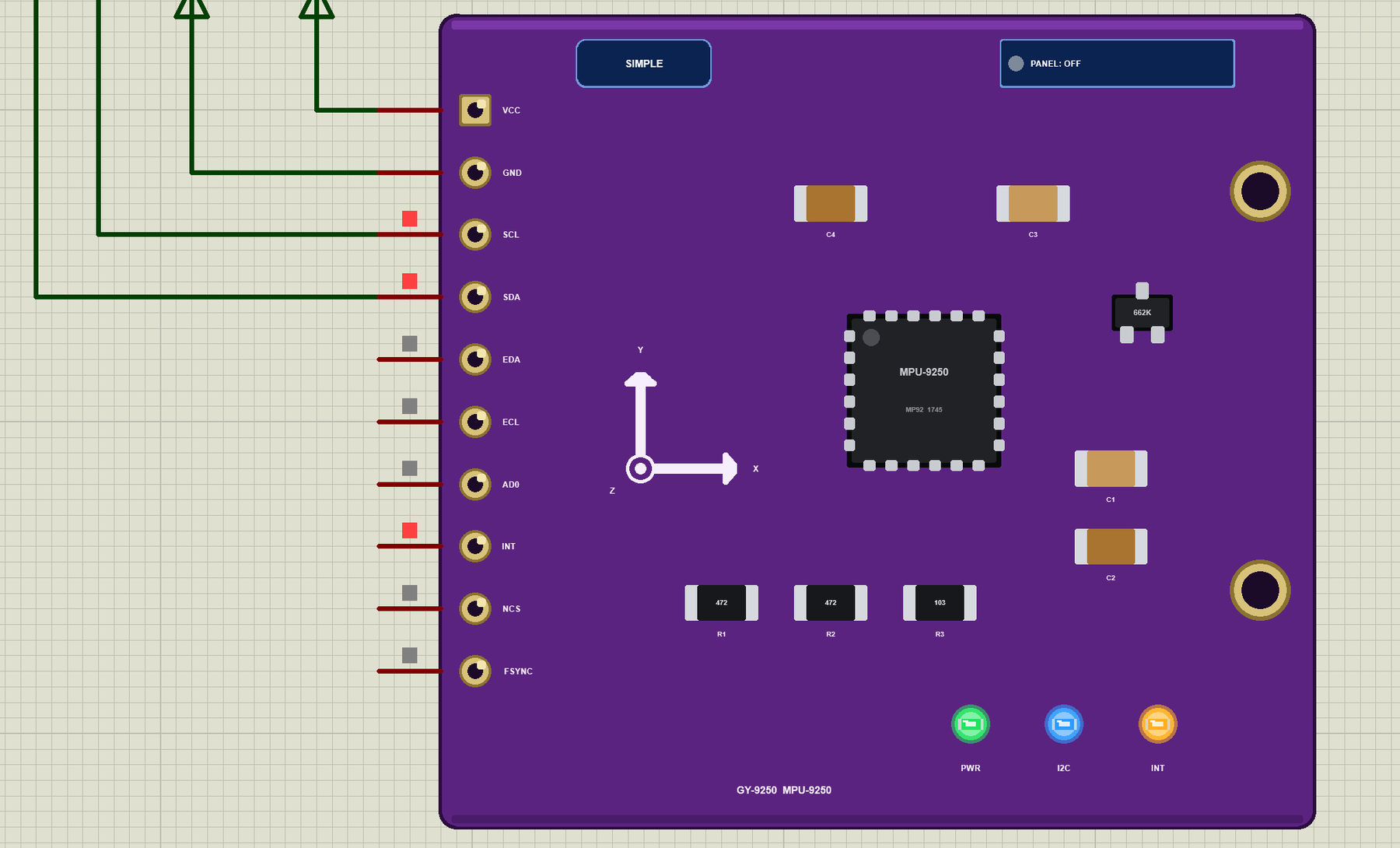
The Advance device keeps the schematic clean: only the module. Its live data opens in a pop-up window at Run, and the OPEN PANEL button on the board brings the window back. The properties set the start: CHIP (MPU9250, MPU9255 or MPU6500), YAW, PITCH and ROLL, FIELD and INCLINATION (the Earth's field, 50 uT, 60 degrees down), TEMP (25 degrees C) and NOISE.
The Demo Circuit
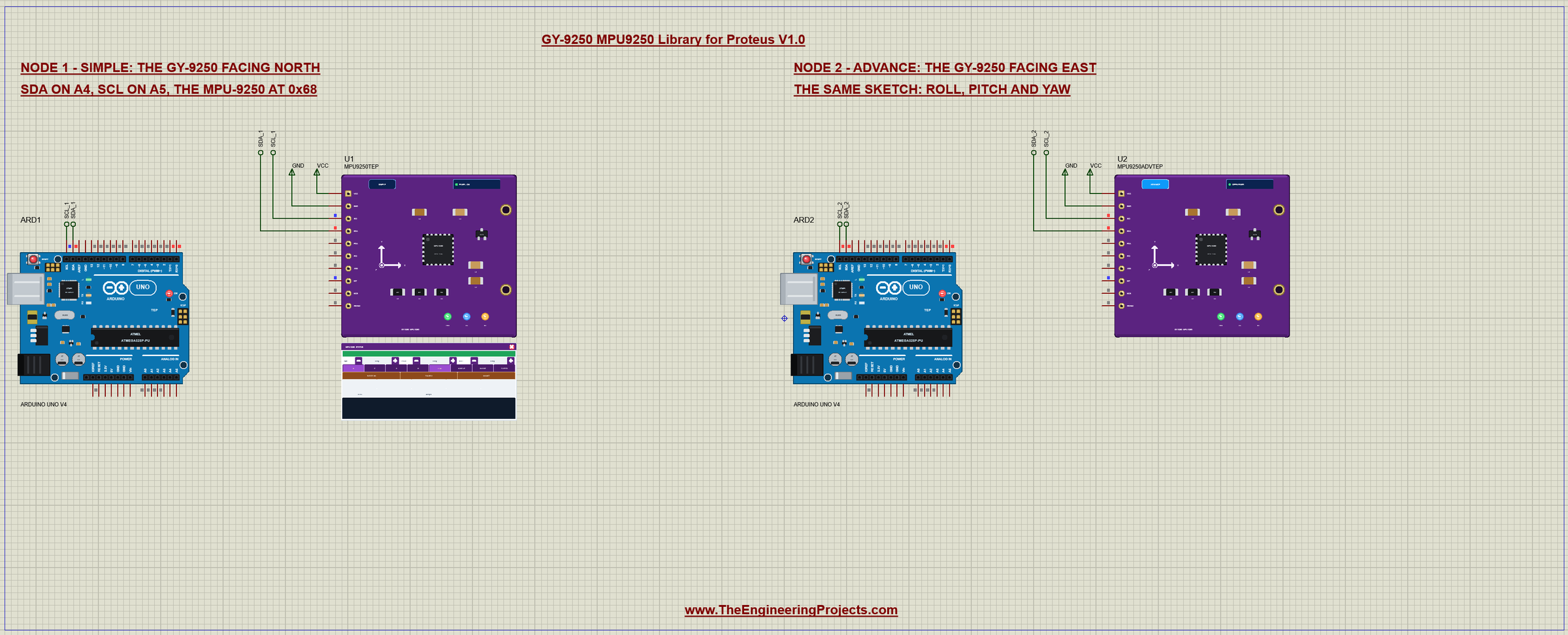
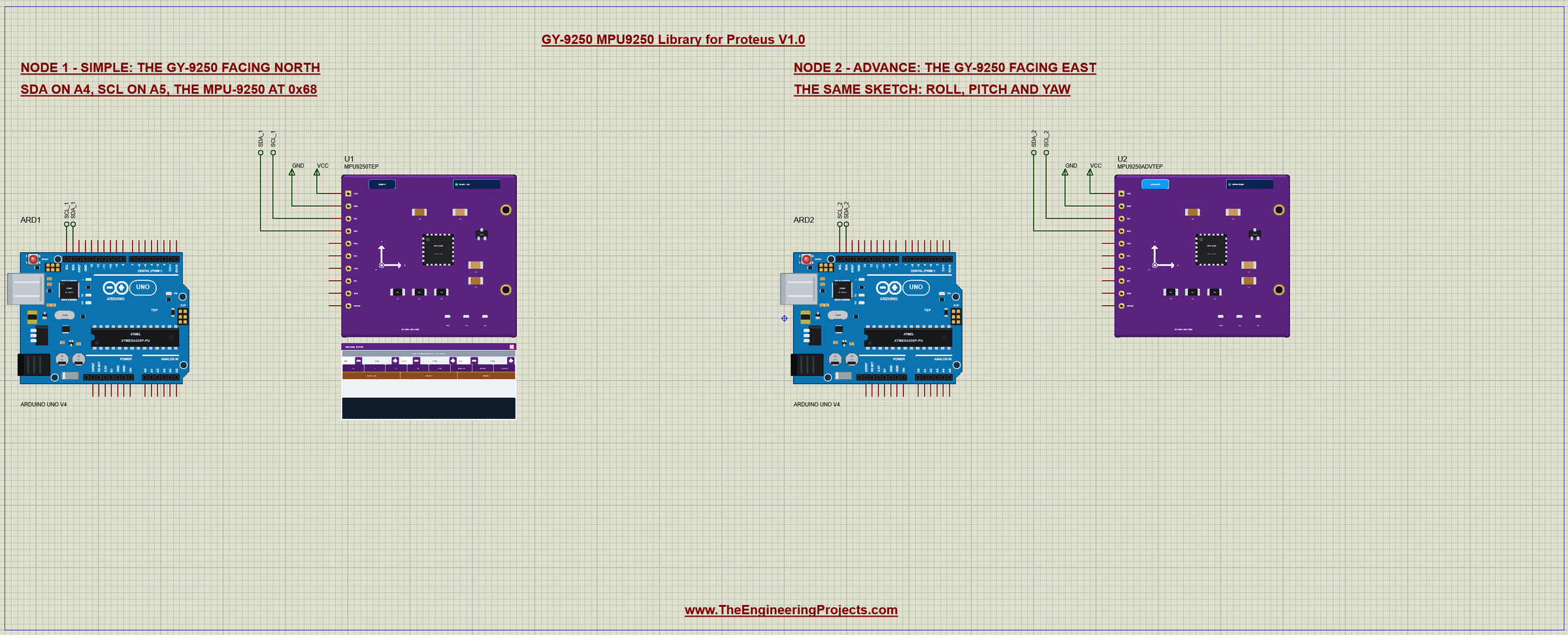
The demo project has two nodes. Each one is an Arduino UNO V4.0 from our Arduino UNO Library for Proteus V4.0 with a GY-9250 on its SDA and SCL pins, which are A4 and A5. Node 1 starts flat and facing north; node 2 starts flat and facing east. Both UNOs run the same GY9250_IMU_Demo.hex.
Wiring
| Module | Arduino UNO |
|---|---|
| VCC | 5V (the regulator gives the chip 3.3 V) |
| GND | GND |
| SCL | A5 (the SCL pin) |
| SDA | A4 (the SDA pin) |
| AD0 | open or GND: 0x68 (VCC: 0x69) |
| INT | open (or an input for data ready) |
| NCS | open (I2C) |
| EDA, ECL, FSYNC | open |
In Proteus, SDA and SCL reach their UNO through net labels, SDA_1 and SCL_1 for node 1 and the same with _2 for node 2. The Wire library turns on the UNO's internal pull-ups, which hold the I2C bus HIGH in the simulation. The serial monitor needs no wires at all, because it is built into the UNO V4.0.
The Arduino Code
The demo sketch uses the MPU9250 library by hideakitai (version 0.4.8), which is a single header. New to Arduino? Start with Arduino Tutorial for Beginners and Introduction to Arduino UNO. The sketch begins with Wire and the library:
#include <Wire.h>
#include "MPU9250.h"
In setup(), mpu.setup() reads WHO_AM_I, resets and configures the MPU (200 Hz, plus or minus 16 g and 2000 dps), sets BYPASS_EN, reads the AK8963's fuse ROM and starts it at 100 Hz. Then the sketch sets the declination to 0, because the library starts with Japan's -7.51 degrees:
void setup() {
  Serial.begin(9600);
  Wire.begin();
  Serial.println(F("TEP GY-9250 IMU - demo (MPU-9250 + AK8963)"));
  Serial.println(F("SDA on A4, SCL on A5"));
  delay(100);
  ok = mpu.setup(MPU_ADDR);
  if (ok) {
    mpu.setMagneticDeclination(0);               // the library starts at -7.51 (Japan): set yours with DECL
    Serial.println(F("found the MPU-9250 at 0x68 and its AK8963 - the hideakitai library"));
  } else {
    Serial.println(F("setup() failed:"));
    who();
  }
  help();
  nextAt = millis() + 500;
}
When setup() fails, who() reads WHO_AM_I itself and names the chip, so an MPU-6500 is caught at once:
void who() {
  const uint8_t w = readReg(MPU_ADDR, 0x75);
  Serial.print(F("WHO: WHO_AM_I "));
  printHex(w);
  if (w == 0x71) Serial.println(F(" = MPU-9250"));
  else if (w == 0x73) Serial.println(F(" = MPU-9255"));
  else if (w == 0x70) Serial.println(F(" = MPU-6500: no magnetometer inside"));
  else Serial.println(F(" = no MPU at 0x68 - check the wiring and AD0"));
  if (w == 0x71 || w == 0x73) {
    Serial.print(F("WHO: AK8963 WIA "));
    printHex(readReg(0x0C, 0x00));
    Serial.println(F(" (0x48 - behind the I2C bypass)"));
  }
}
The loop calls update() as often as it can. This matters: the AK8963 measures 100 times a second, and when the sketch reads it more slowly, ST1 shows a skipped sample (DOR) and the library drops that reading. Twice a second the sketch prints the roll, the pitch and the yaw:
void loop() {
  while (Serial.available()) {
    const char c = Serial.read();
    if (c == '\r' || c == '\n') { if (lineLen) { line[lineLen] = 0; command(line); lineLen = 0; } }
    else if (lineLen < sizeof line - 1) line[lineLen++] = c;
  }
  // update() as often as the loop runs: it reads the magnetometer only when new data is there (100 Hz)
  if (ok && mpu.update() && running && (long)(millis() - nextAt) >= 0) { printReading(); nextAt += 500; }
}
void printReading() {
Serial.print('#'); Serial.print(++count);
Serial.print(F(" roll ")); Serial.print(mpu.getRoll(), 1);
Serial.print(F(" pitch ")); Serial.print(mpu.getPitch(), 1);
Serial.print(F(" yaw ")); Serial.print(mpu.getYaw(), 1);
Serial.print(F(" ")); Serial.print(mpu.getTemperature(), 1);
Serial.println(F(" C"));
}The HEX file is in the package, so you do not need the Arduino IDE to run the demo. To change the sketch, install "MPU9250" by hideakitai from the Library Manager, open the sketch in the Arduino IDE and export the compiled binary, as in How to get the HEX file from Arduino. It needs 29,252 bytes of flash and 1,241 bytes of RAM.
The Serial Monitor
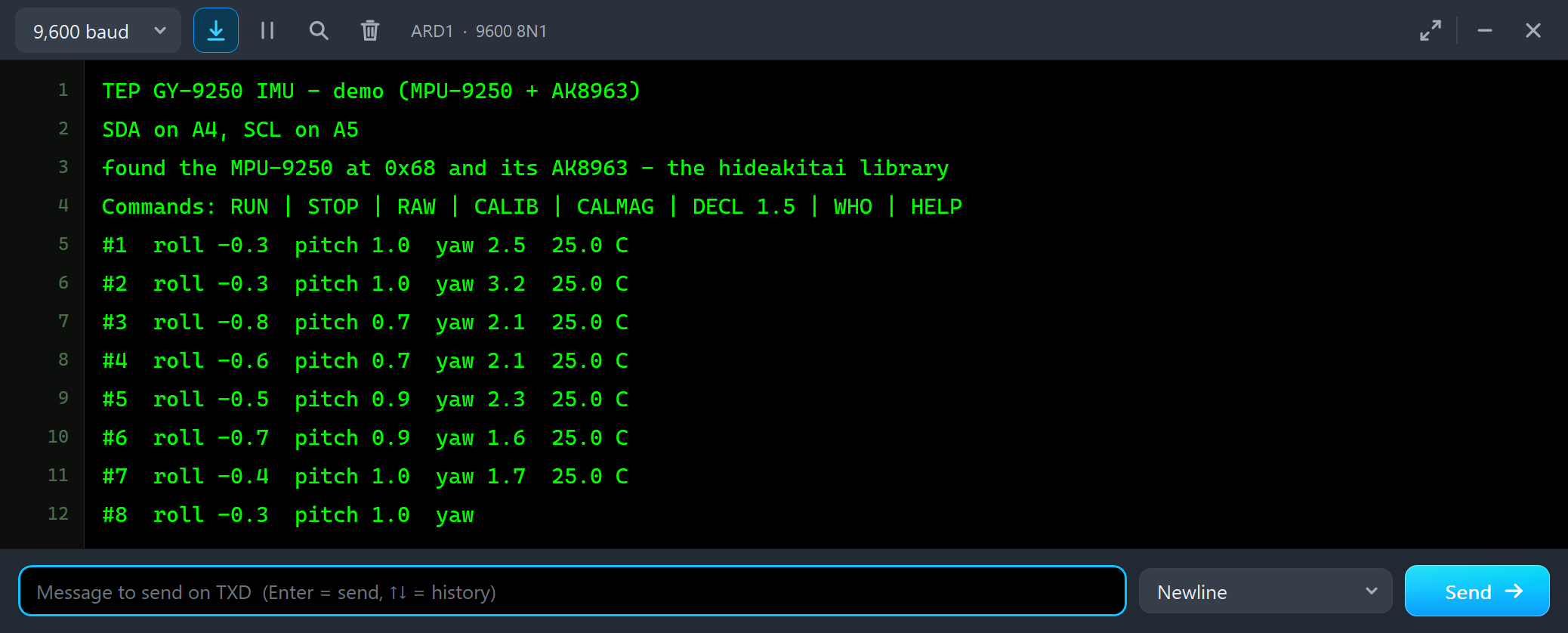
Both UNOs have the serial monitor built in, and it opens at Run. The screenshots use its Simple interface. Node 1 starts like this:
TEP GY-9250 IMU - demo (MPU-9250 + AK8963)
SDA on A4, SCL on A5
found the MPU-9250 at 0x68 and its AK8963 - the hideakitai library
Commands: RUN | STOP | RAW | CALIB | CALMAG | DECL 1.5 | WHO | HELP
#1  roll -0.3  pitch 1.0  yaw 2.5  25.0 C
#2  roll -0.3  pitch 1.0  yaw 3.2  25.0 C
#3  roll -0.8  pitch 0.7  yaw 2.1  25.0 C
#4  roll -0.6  pitch 0.7  yaw 2.1  25.0 C
The board lies flat and faces north, so all three angles sit close to zero. The pitch reads about one degree: the accelerometer has a small offset of its own, as a real one does, and CALIB removes it. Node 2 faces east, and its first lines show the Madgwick filter at work:
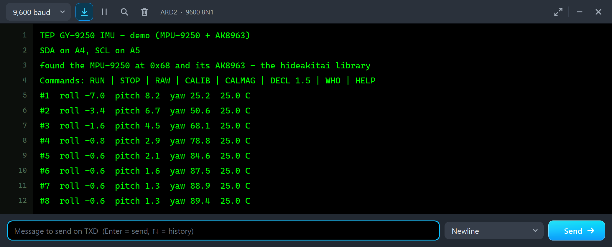
#1  roll -7.0  pitch 8.2  yaw 25.2  25.0 C
#2  roll -3.4  pitch 6.7  yaw 50.6  25.0 C
#3  roll -1.6  pitch 4.5  yaw 68.1  25.0 C
#4  roll -0.8  pitch 2.9  yaw 78.8  25.0 C
#5  roll -0.6  pitch 2.1  yaw 84.6  25.0 C
#6  roll -0.6  pitch 1.6  yaw 87.5  25.0 C
#7  roll -0.6  pitch 1.3  yaw 88.9  25.0 C
#8  roll -0.6  pitch 1.3  yaw 89.4  25.0 C
The filter starts at north and corrects itself a little with every update, so the yaw takes about four seconds to reach east. The yaw is the library's aircraft angle: east is +90, and west would be -90.
Turn the Board
Now let's turn the board while the simulation runs. We clicked E on U1's STATUS panel with the mouse:
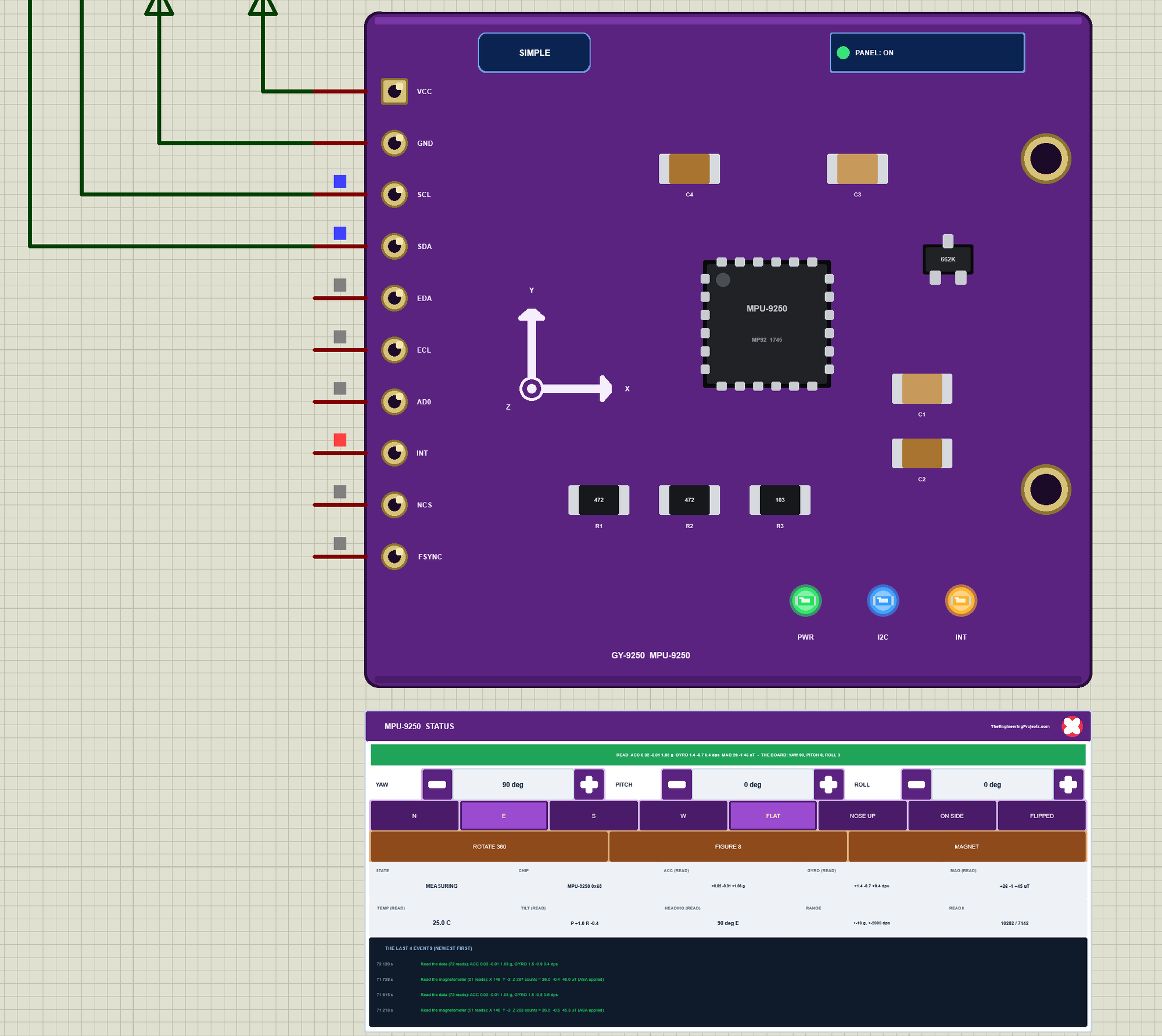
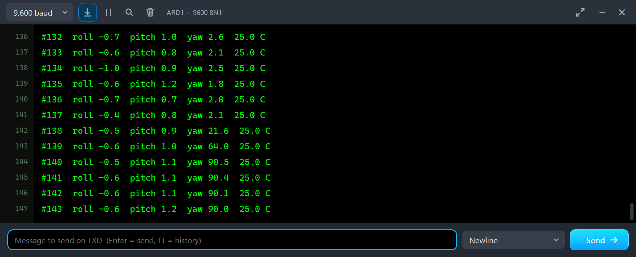
#137  roll -0.4  pitch 0.8  yaw 2.1  25.0 C
#138  roll -0.5  pitch 0.9  yaw 21.6  25.0 C
#139  roll -0.6  pitch 1.0  yaw 64.0  25.0 C
#140  roll -0.5  pitch 1.1  yaw 90.5  25.0 C
#141  roll -0.6  pitch 1.1  yaw 90.4  25.0 C
This time the yaw follows within a second, because the gyro saw the turn: the board turned smoothly, and the filter integrated the rotation instead of waiting for the magnetometer. Then two clicks on the pitch's +:
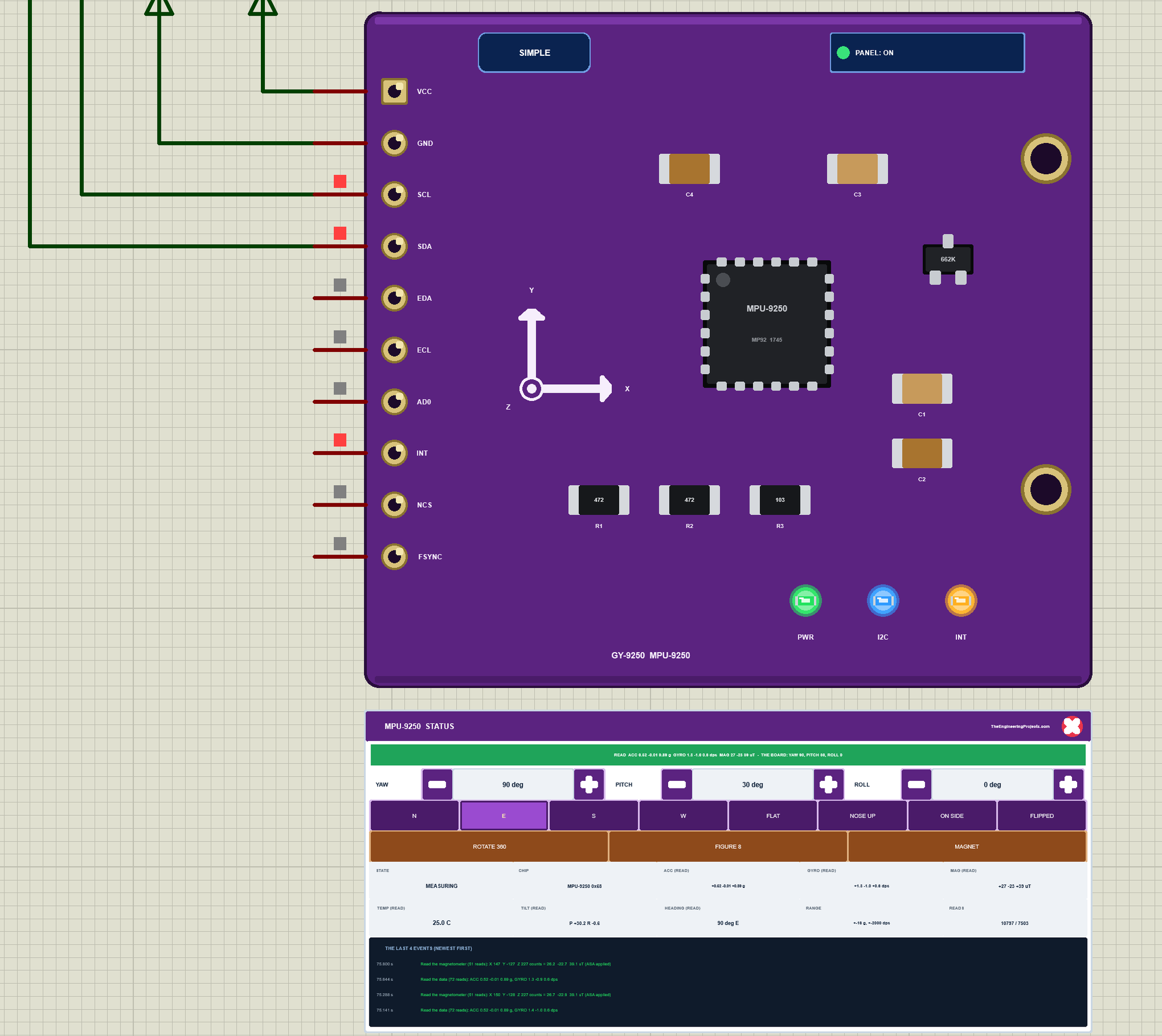
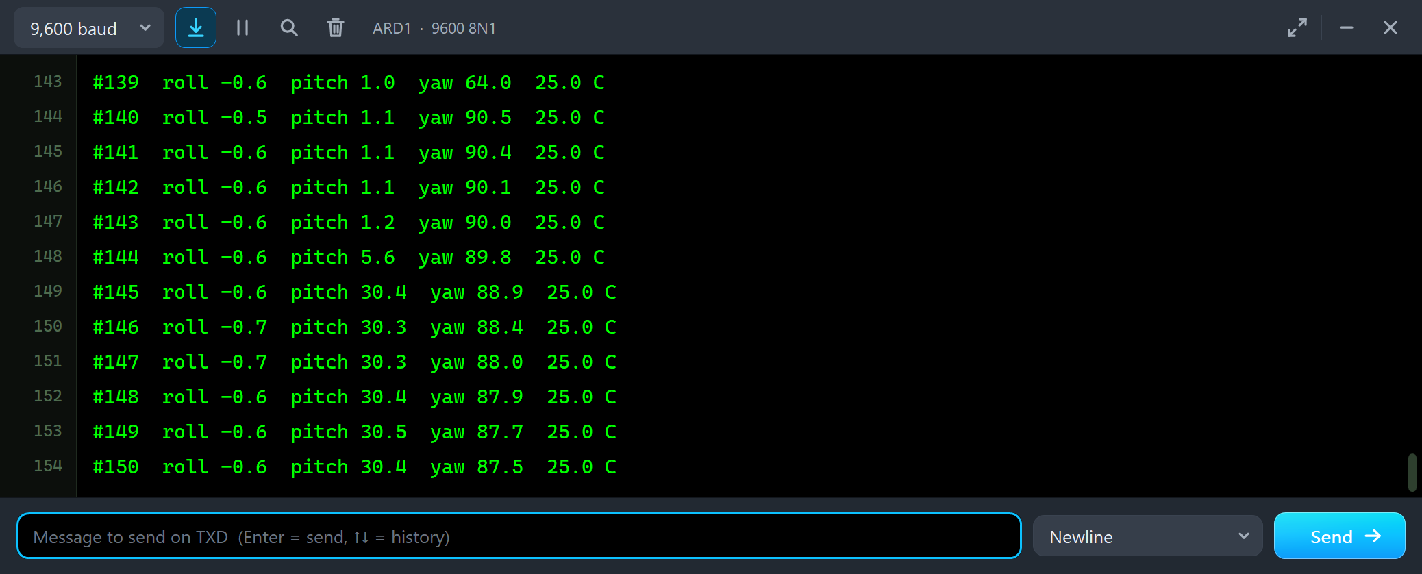
#143  roll -0.6  pitch 1.2  yaw 90.0  25.0 C
#144  roll -0.6  pitch 5.6  yaw 89.8  25.0 C
#145  roll -0.6  pitch 30.4  yaw 88.9  25.0 C
#146  roll -0.7  pitch 30.3  yaw 88.4  25.0 C
#147  roll -0.7  pitch 30.3  yaw 88.0  25.0 C
The pitch reads 30.4, the board 30. The yaw moves by about two degrees: with the nose up, the magnetometer has to be turned level before it gives a heading, and every small offset shows a little more. Then ROTATE 360 with the nose still up:
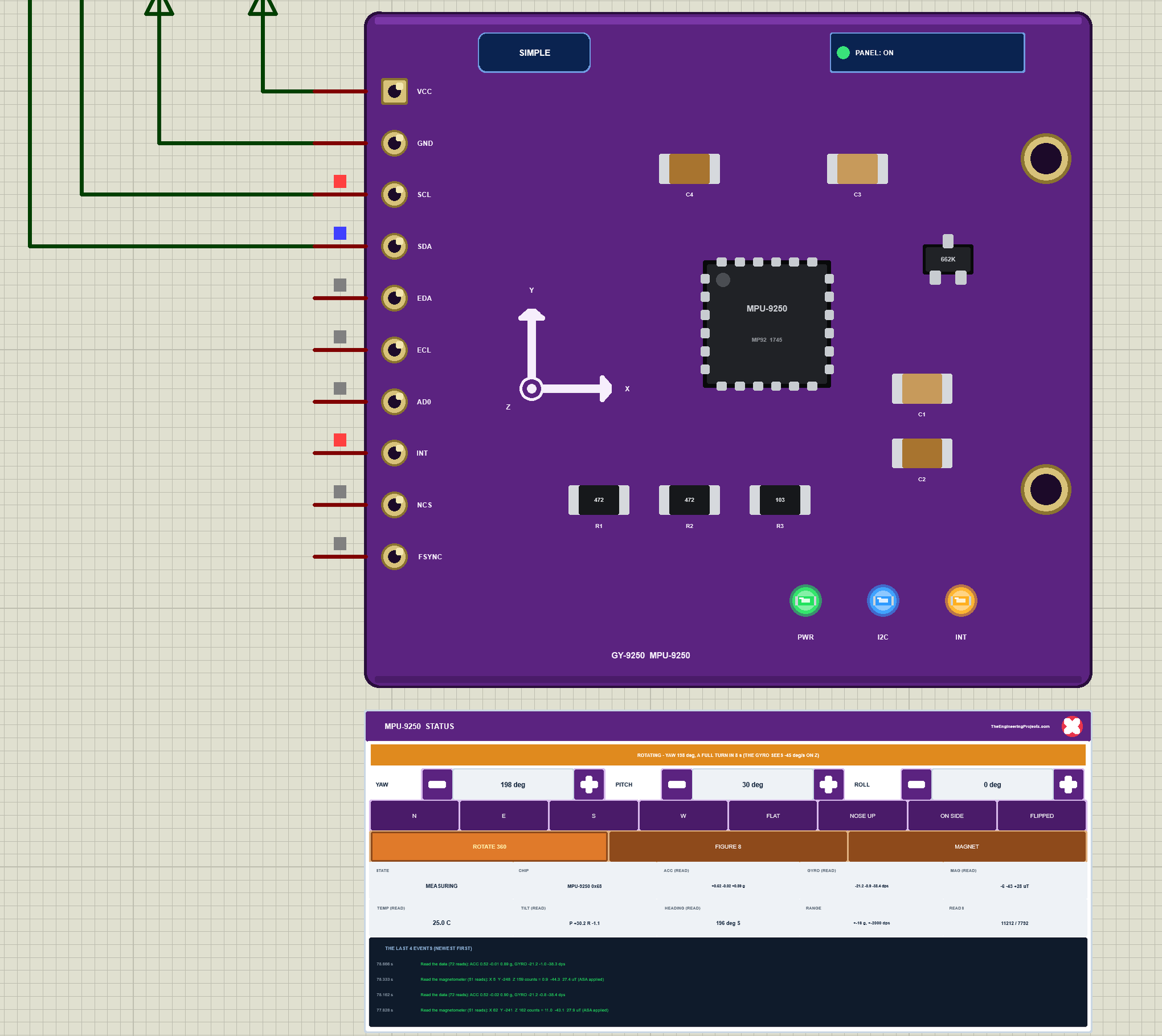
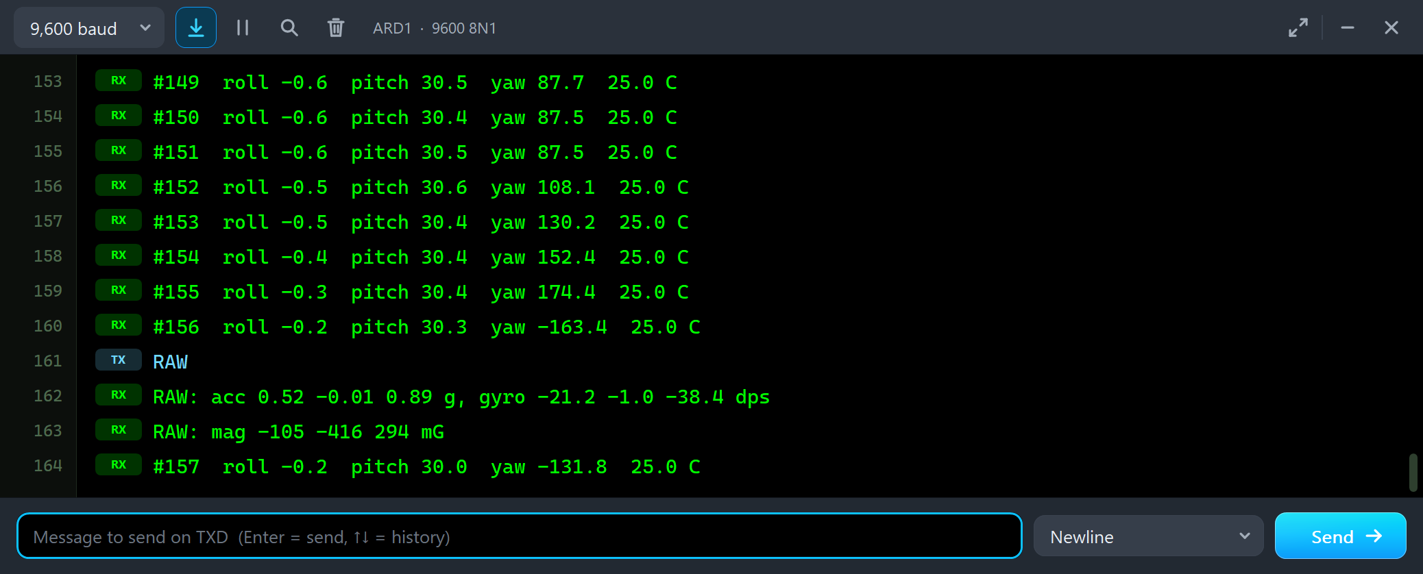
#151  roll -0.6  pitch 30.5  yaw 87.5  25.0 C
#152  roll -0.5  pitch 30.6  yaw 108.1  25.0 C
#153  roll -0.5  pitch 30.4  yaw 130.2  25.0 C
#154  roll -0.4  pitch 30.4  yaw 152.4  25.0 C
#155  roll -0.3  pitch 30.4  yaw 174.4  25.0 C
#156  roll -0.2  pitch 30.3  yaw -163.4  25.0 C
RAW
RAW: acc 0.52 -0.01 0.89 g, gyro -21.2 -1.0 -38.4 dps
RAW: mag -105 -416 294 mG
The board turns about the vertical at 45 degrees a second. With the nose up by 30 degrees, that turn is not about the gyro's own Z axis any more: it splits into about 39 degrees a second on Z and 22 on X. The filter puts it back together, and the yaw grows by about 22 degrees on every line, half a second apart. Note the wrap from 174.4 to -163.4: the library keeps the yaw between -180 and +180.
The Advance Pop-Up Window
At Run, the Advance module opens its own window, MPU9250 IMU, with the look of our TEP Serial Monitor Advance for Proteus. It has three tabs, Sensor, Event log and Tests, plus Settings and Help behind the gear and question mark icons. The status bar at the bottom always shows the board's attitude, the pitch and the roll from the reading, and the state.
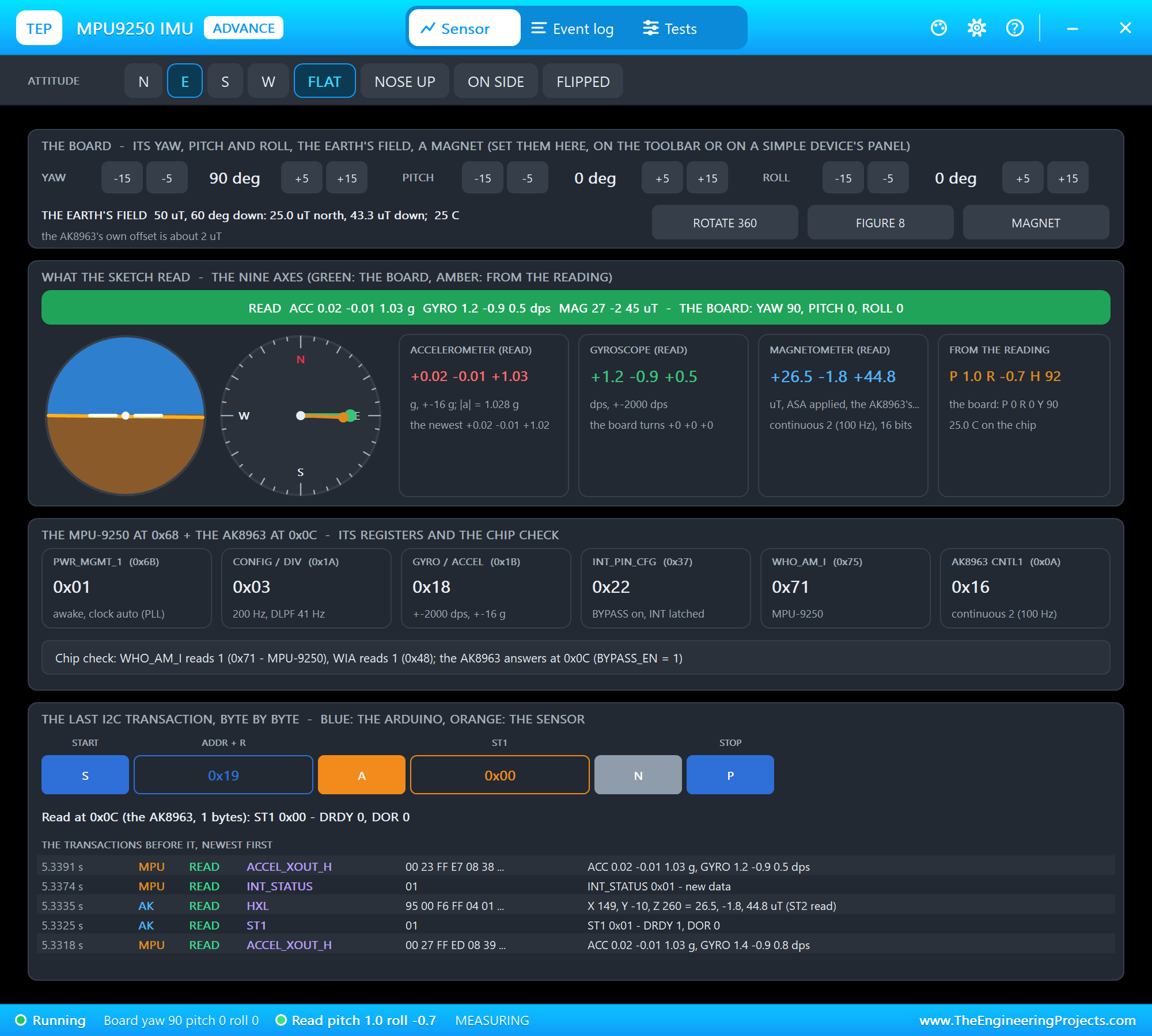
The toolbar carries the eight attitudes. The top card is the board: the yaw, the pitch and the roll with -15, -5, +5 and +15 degrees, the Earth's field and the three actions. What the sketch read draws an attitude ball and a compass rose, green for the board and amber for the reading, next to the accelerometer, the gyroscope, the magnetometer and the pitch, roll and heading worked out from them. The registers card shows PWR_MGMT_1, the rate, the ranges, INT_PIN_CFG with the bypass, WHO_AM_I and the AK8963's mode, and the chip check. The last card draws the last I2C transaction byte by byte. We clicked the pitch's +15 twice:
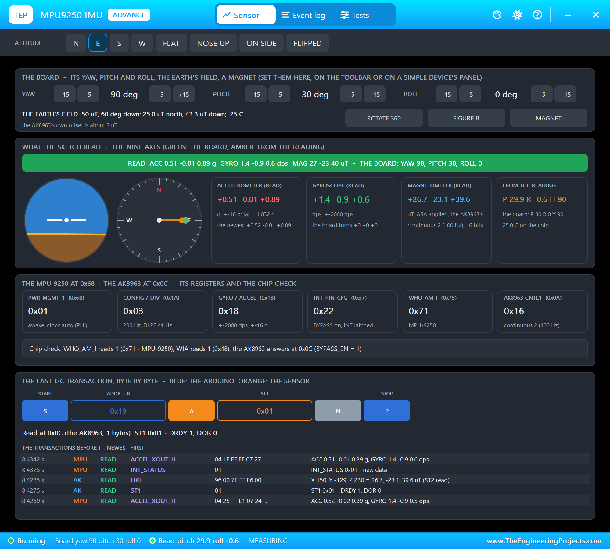
Then the roll's -15 twice. The monitor shows both steps:
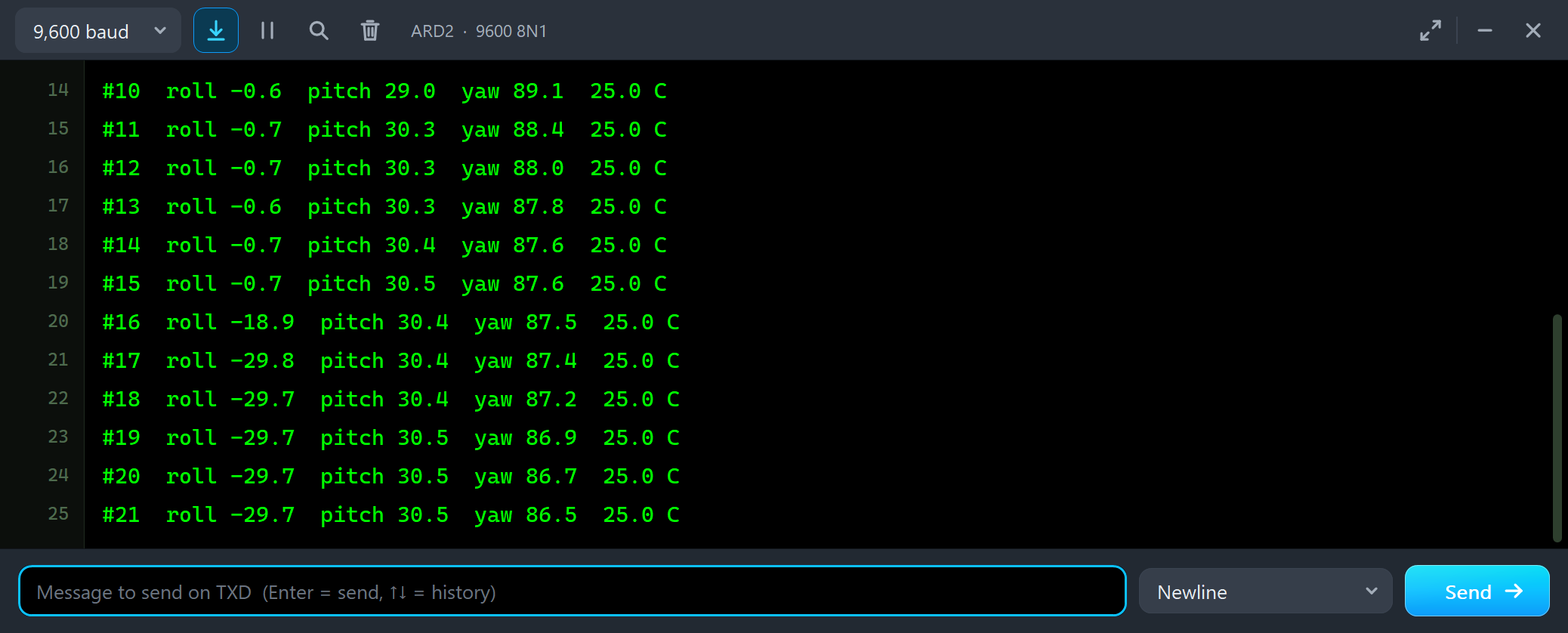
#14  roll -0.7  pitch 30.4  yaw 87.6  25.0 C
#15  roll -0.7  pitch 30.5  yaw 87.6  25.0 C
#16  roll -18.9  pitch 30.4  yaw 87.5  25.0 C
#17  roll -29.8  pitch 30.4  yaw 87.4  25.0 C
#18  roll -29.7  pitch 30.4  yaw 87.2  25.0 C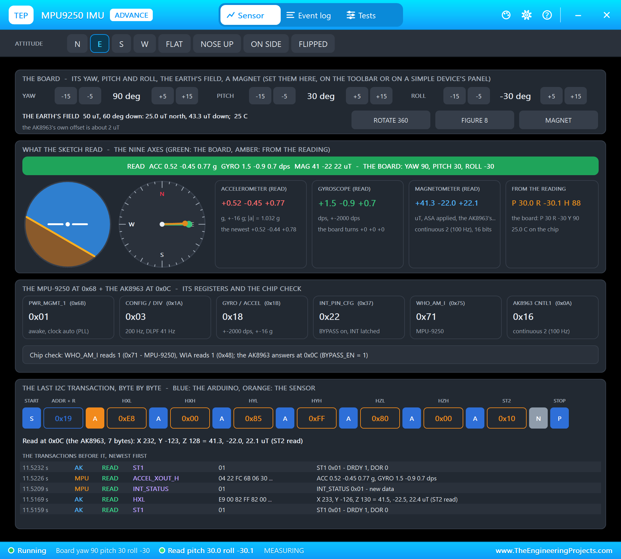
A negative roll is the left side down, so the horizon's right end drops in the ball, as in an aircraft. Then we clicked FLAT and typed RAW, which prints the nine values the library holds:
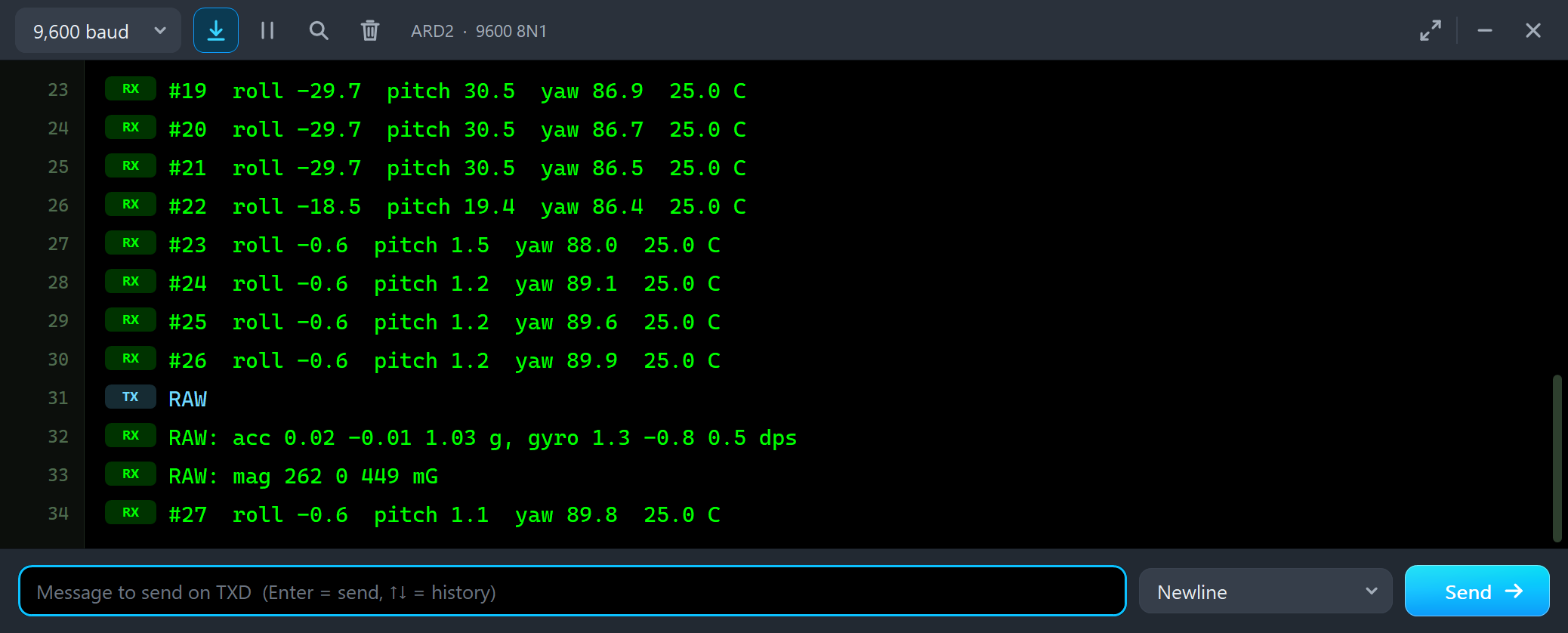
#26  roll -0.6  pitch 1.2  yaw 89.9  25.0 C
RAW
RAW: acc 0.02 -0.01 1.03 g, gyro 1.3 -0.8 0.5 dps
RAW: mag 262 0 449 mG
Z carries gravity, 1.03 g with the chip's small offset. The gyro is not zero although the board is still: 1.3, -0.8 and 0.5 dps is its bias. The filter copes with it, but an angle integrated from the gyro alone would drift by more than a degree a second. The field is in milligauss (10 mG = 1 uT) on the AK8963's axes.
ROTATE 360
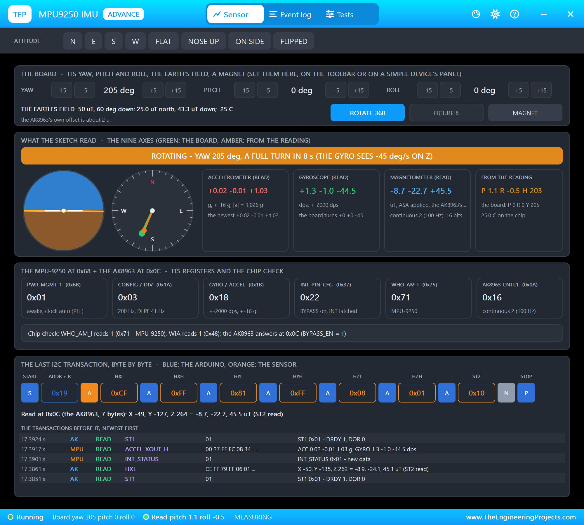
Now the gyro at work. We clicked ROTATE 360, a full turn in 8 seconds:
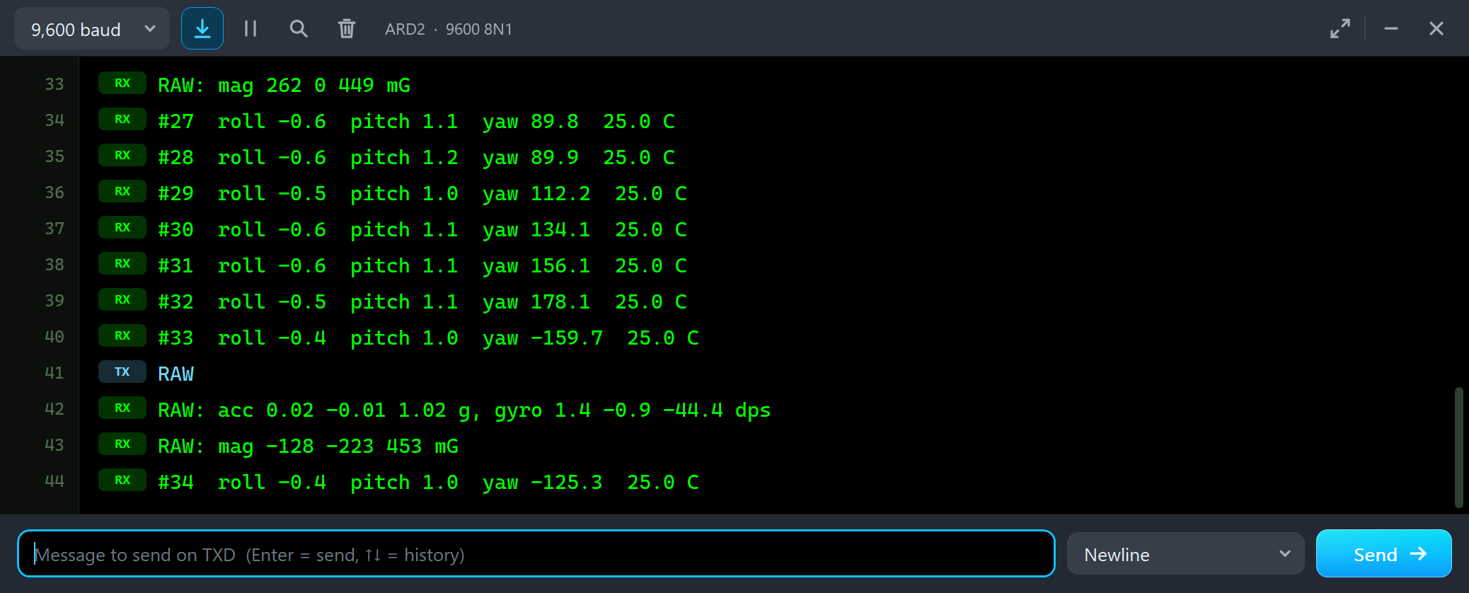
#28  roll -0.6  pitch 1.2  yaw 89.9  25.0 C
#29  roll -0.5  pitch 1.0  yaw 112.2  25.0 C
#30  roll -0.6  pitch 1.1  yaw 134.1  25.0 C
#31  roll -0.6  pitch 1.1  yaw 156.1  25.0 C
#32  roll -0.5  pitch 1.1  yaw 178.1  25.0 C
#33  roll -0.4  pitch 1.0  yaw -159.7  25.0 C
RAW
RAW: acc 0.02 -0.01 1.02 g, gyro 1.4 -0.9 -44.4 dps
RAW: mag -128 -223 453 mG
The board turns clockwise seen from above, 45 degrees a second. The gyro's Z axis points up, so a clockwise turn is negative: -44.4 dps, the 45 degrees a second plus the 0.6 of bias.
A Magnet on the Board
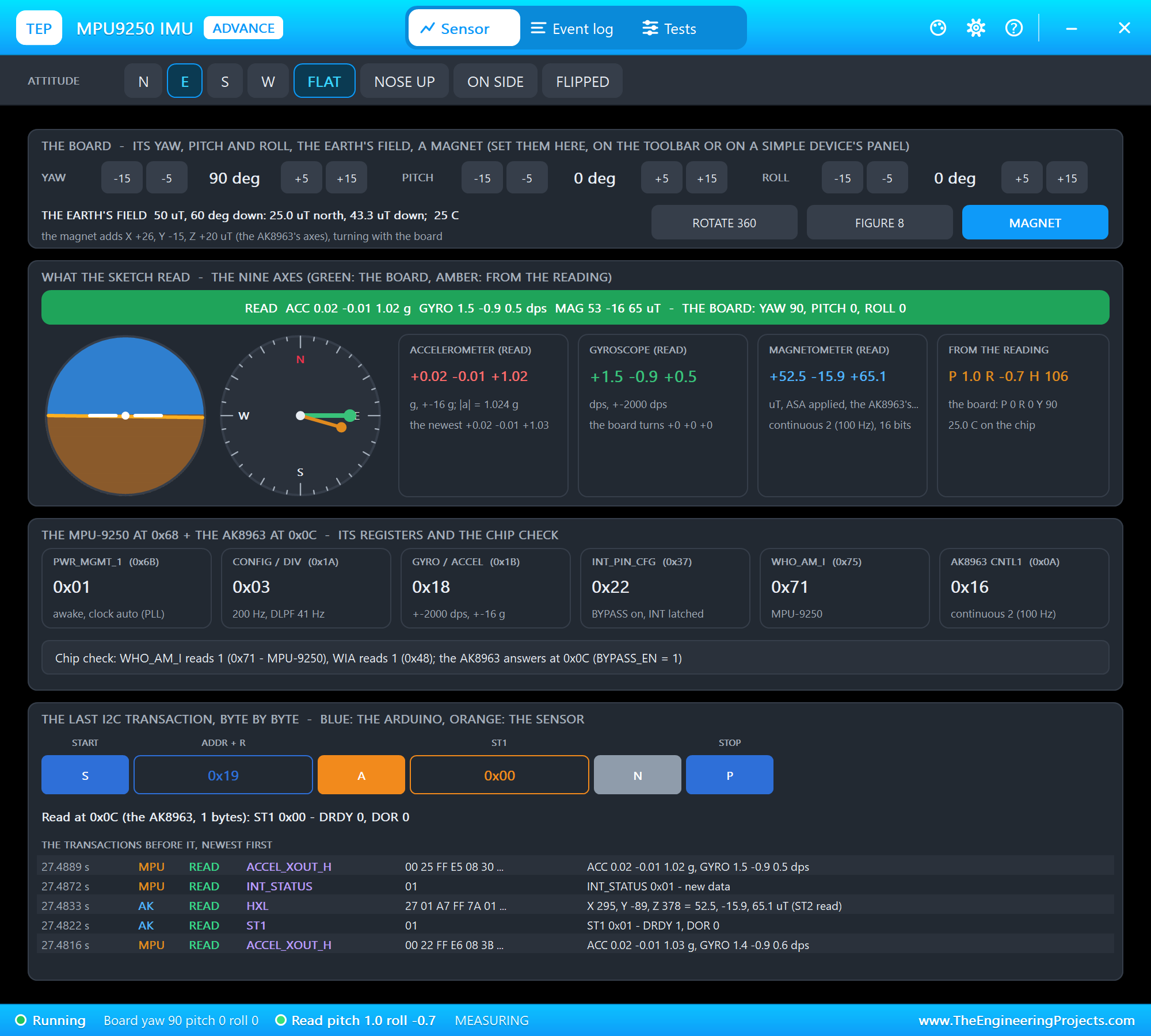
Now the thing that pulls a magnetometer off. With the board flat at east, we clicked MAGNET: a small magnet that sits on the board and turns with it.
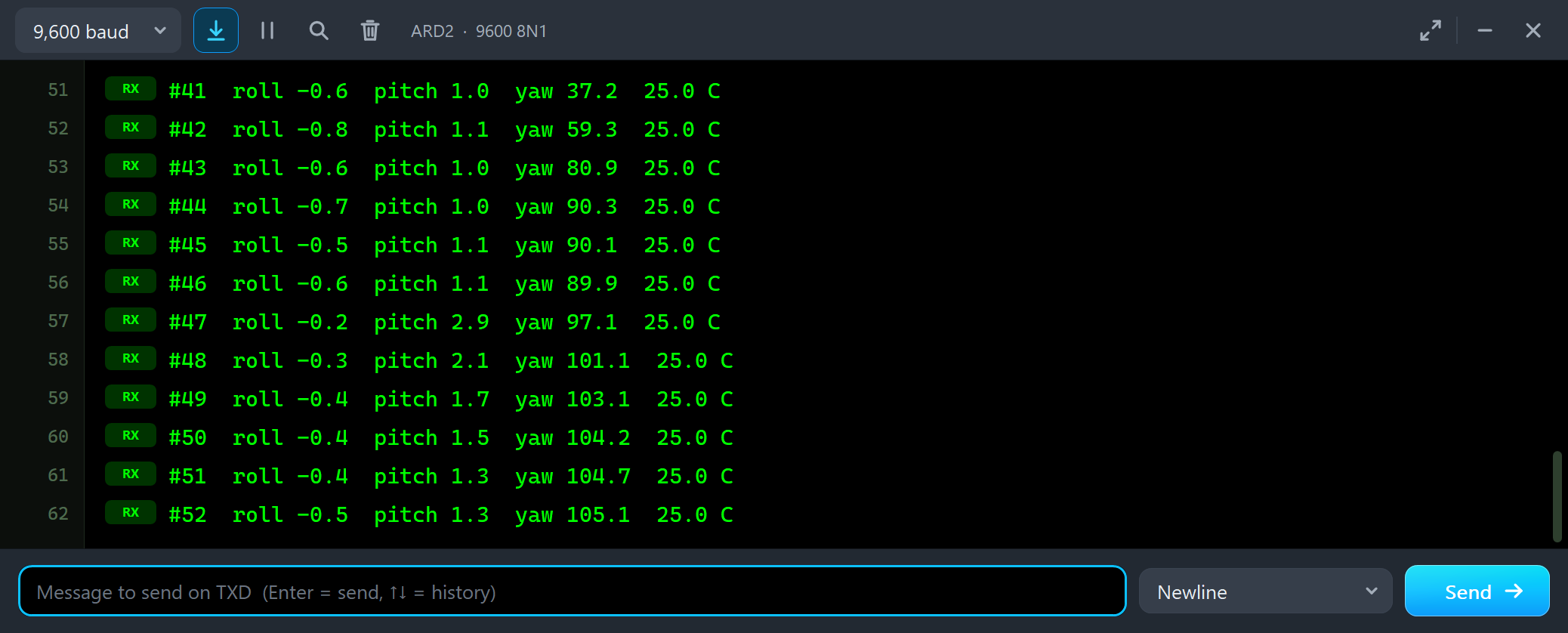
#45  roll -0.5  pitch 1.1  yaw 90.1  25.0 C
#46  roll -0.6  pitch 1.1  yaw 89.9  25.0 C
#47  roll -0.2  pitch 2.9  yaw 97.1  25.0 C
#48  roll -0.3  pitch 2.1  yaw 101.1  25.0 C
#49  roll -0.4  pitch 1.7  yaw 103.1  25.0 C
#50  roll -0.4  pitch 1.5  yaw 104.2  25.0 C
#51  roll -0.4  pitch 1.3  yaw 104.7  25.0 C
#52  roll -0.5  pitch 1.3  yaw 105.1  25.0 C
The yaw does not jump: the filter trusts the gyro, which says the board is still, and lets the magnetometer pull it over a few seconds. It ends 15 degrees off. Note the short bump in the pitch: the filter tried to explain the new field with a tilt.
CALMAG and FIGURE 8
The magnet turns with the board, so it shifts every reading by the same amount: hard iron. The library's calibrateMag() finds it from the minimum and the maximum of each axis while the board turns through every direction. We typed CALMAG and clicked FIGURE 8, 20 seconds of turning and tilting:
void calmag() {
  Serial.println(F("CALMAG: press FIGURE 8 now - 4 s, then 15 s of turning"));
  mpu.calibrateMag();
  Serial.print(F("CALMAG: bias "));
  Serial.print(mpu.getMagBiasX(), 0); Serial.print(' '); Serial.print(mpu.getMagBiasY(), 0); Serial.print(' '); Serial.print(mpu.getMagBiasZ(), 0);
  Serial.print(F(" mG, scale "));
  Serial.print(mpu.getMagScaleX(), 2); Serial.print(' '); Serial.print(mpu.getMagScaleY(), 2); Serial.print(' '); Serial.println(mpu.getMagScaleZ(), 2);
}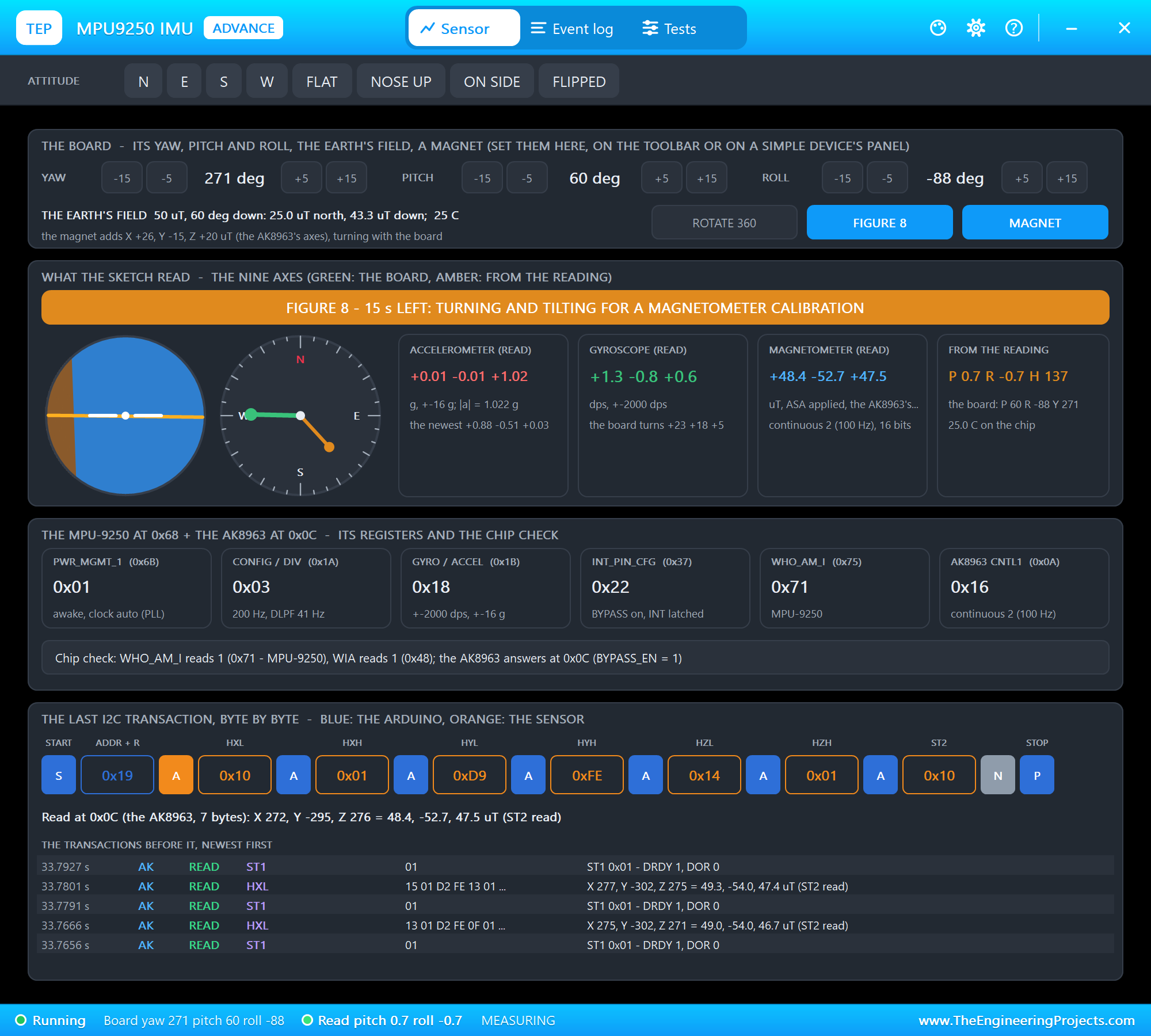
During the calibration the library reads only the magnetometer, so the accelerometer and gyro tiles keep the values from before. After about 25 seconds:
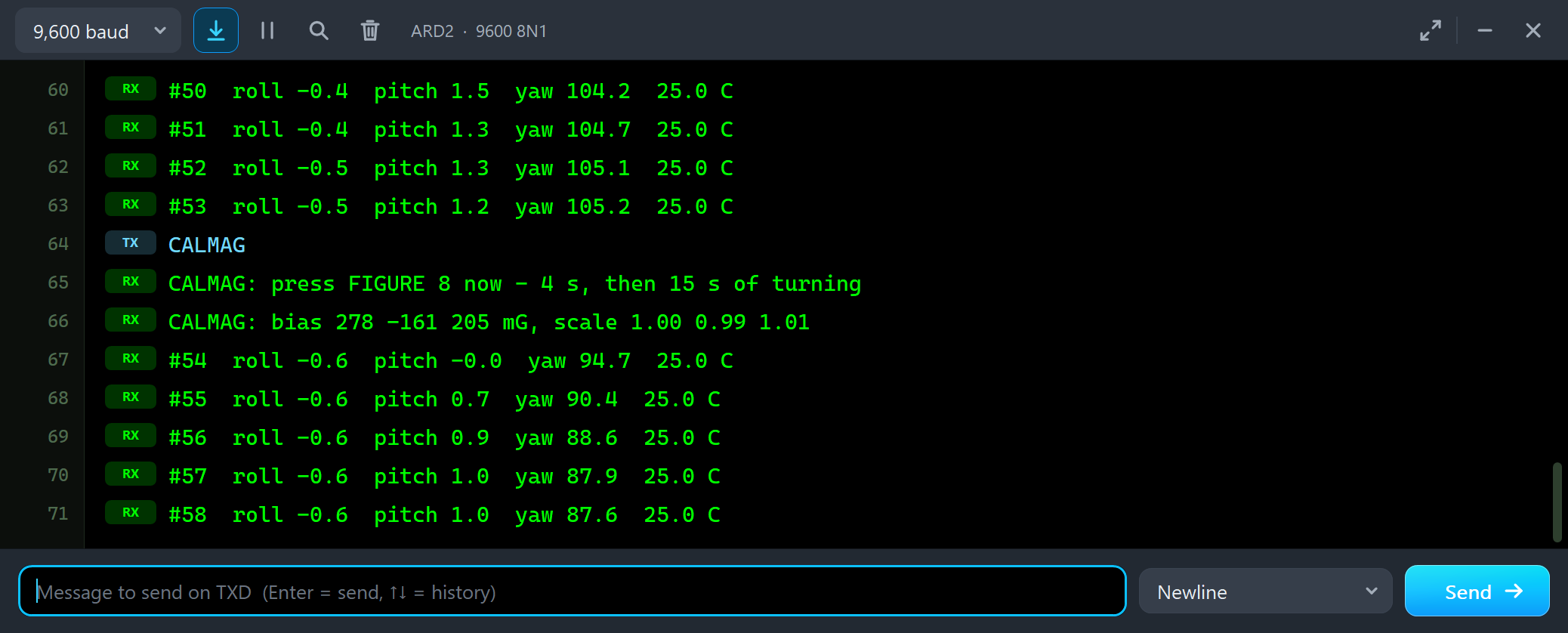
CALMAG
CALMAG: press FIGURE 8 now - 4 s, then 15 s of turning
CALMAG: bias 278 -161 205 mG, scale 1.00 0.99 1.01
#54  roll -0.6  pitch -0.0  yaw 94.7  25.0 C
#55  roll -0.6  pitch 0.7  yaw 90.4  25.0 C
#56  roll -0.6  pitch 0.9  yaw 88.6  25.0 C
#57  roll -0.6  pitch 1.0  yaw 87.9  25.0 C
#58  roll -0.6  pitch 1.0  yaw 87.6  25.0 C
The bias is in milligauss: 278, -161 and 205 mG, the magnet's X +26, Y -15 and Z +20 uT plus the AK8963's own small offset. The scale stays close to 1, because the board went everywhere. With the bias subtracted, the yaw settles back near 88 to 90 degrees, magnet or not. The Attitude & calibration tool shows the same arithmetic:
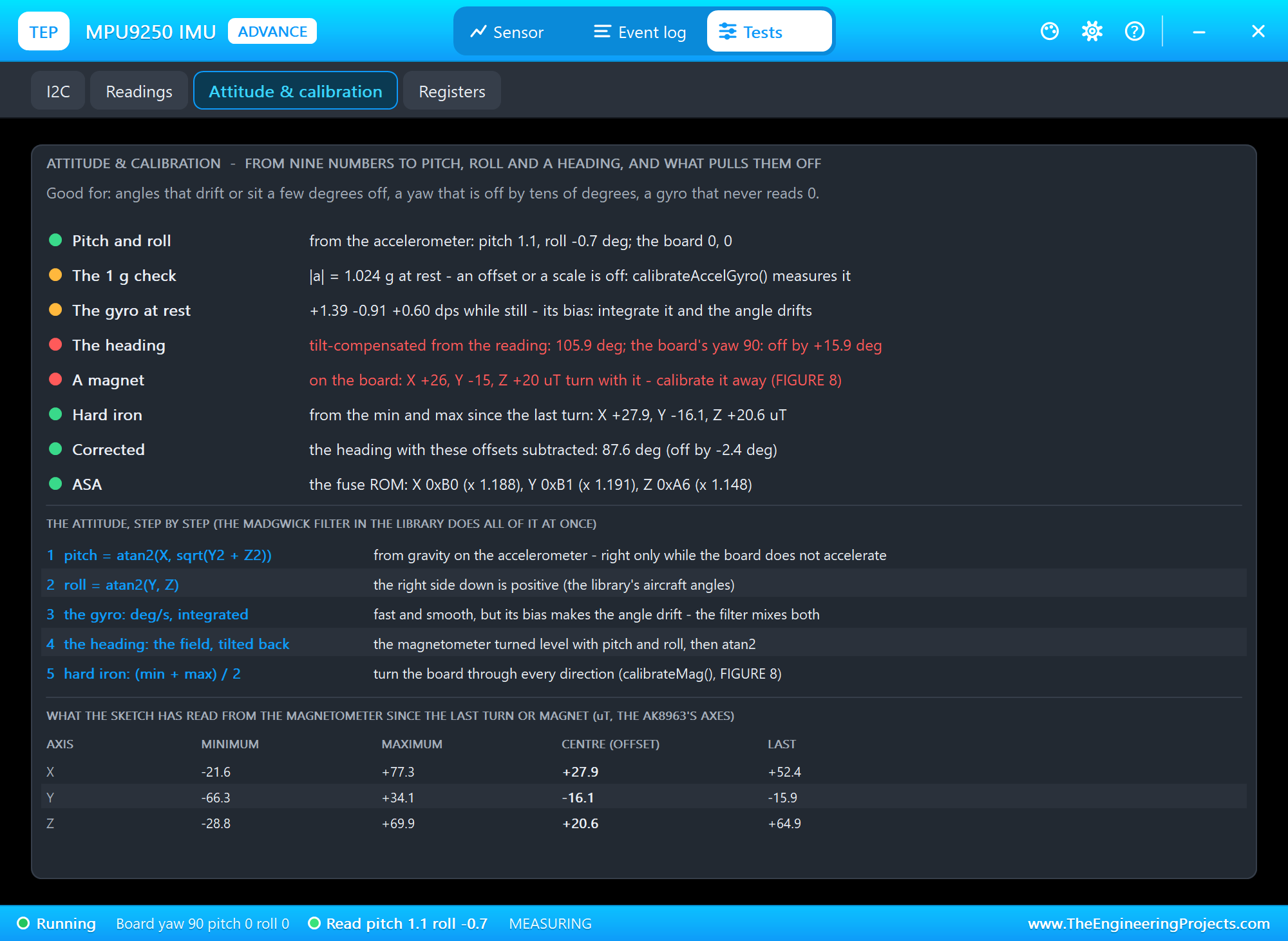
It checks the pitch and the roll from the accelerometer, the 1 g of gravity, the gyro at rest, the heading tilt-compensated from the reading, the magnet and the ASA values. From the minimum and the maximum since the last turn it works out the offsets - X +27.9, Y -16.1 and Z +20.6 uT - and the heading corrected with them, 87.6 degrees: the same as the library's yaw.
CALIB, RAW and WHO
Last, the accelerometer and the gyro. CALIB calls calibrateAccelGyro(): 40 ms of samples through the FIFO, averaged into the chip's offset registers. The board must be still and flat. Then RAW and WHO:
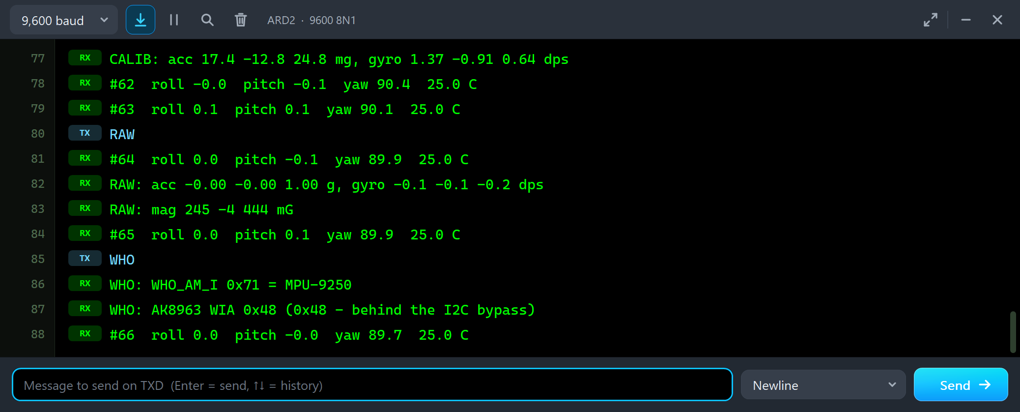
CALIB: acc 17.4 -12.8 24.8 mg, gyro 1.37 -0.91 0.64 dps
#62  roll -0.0  pitch -0.1  yaw 90.4  25.0 C
#63  roll 0.1  pitch 0.1  yaw 90.1  25.0 C
RAW
#64  roll 0.0  pitch -0.1  yaw 89.9  25.0 C
RAW: acc -0.00 -0.00 1.00 g, gyro -0.1 -0.1 -0.2 dps
RAW: mag 245 -4 444 mG
#65  roll 0.0  pitch 0.1  yaw 89.9  25.0 C
WHO
WHO: WHO_AM_I 0x71 = MPU-9250
WHO: AK8963 WIA 0x48 (0x48 - behind the I2C bypass)
The offsets match the chip's own: 17.4, -12.8 and 24.8 mg, and 1.37, -0.91 and 0.64 dps. After it, RAW reads exactly 1.00 g, the gyro reads about 0.1 dps, the roll and the pitch sit at 0.0 and 0.1, and the yaw at 90. WHO confirms the chip: WHO_AM_I 0x71, and 0x48 from the AK8963 behind the bypass.
The Trap: an MPU-6500 on the Board
To see the trap, we set U2's CHIP property to MPU6500 and ran the demo again:
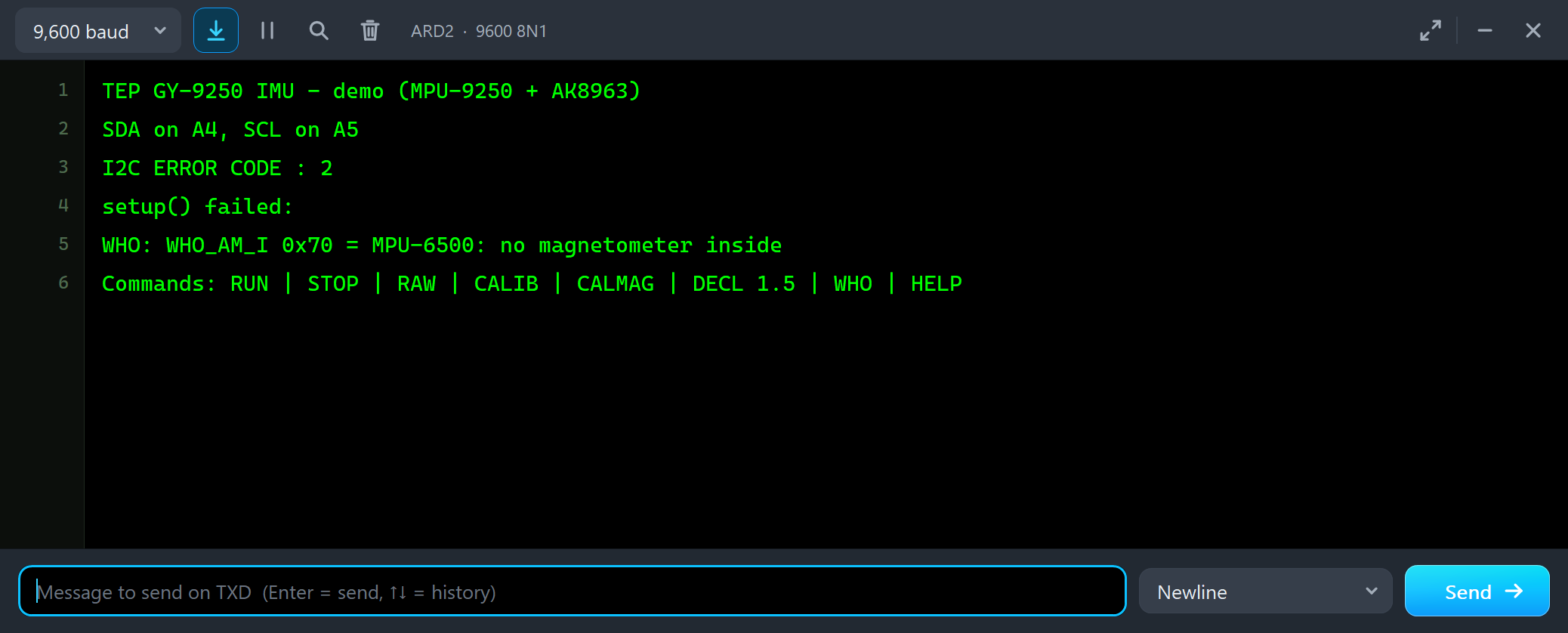
TEP GY-9250 IMU - demo (MPU-9250 + AK8963)
SDA on A4, SCL on A5
I2C ERROR CODE : 2
setup() failed:
WHO: WHO_AM_I 0x70 = MPU-6500: no magnetometer inside
Commands: RUN | STOP | RAW | CALIB | CALMAG | DECL 1.5 | WHO | HELP
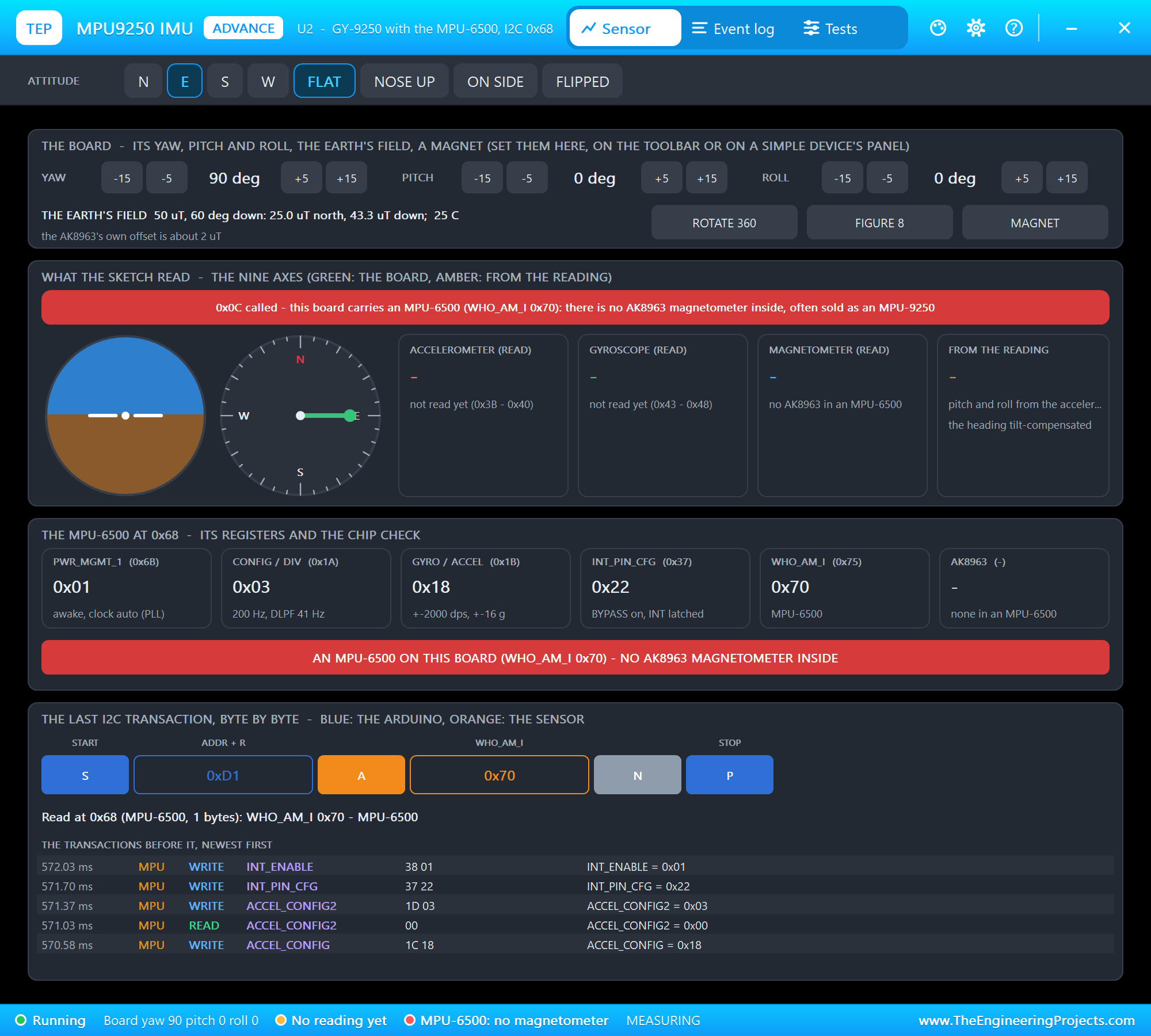
The library accepts the MPU-6500's WHO_AM_I, sets everything up, and then finds nobody at 0x0C: it prints the Wire error 2, a NACK on the address, and setup() returns false. The sketch's own WHO check explains why. The pop-up shows it in red:
The Test Tools
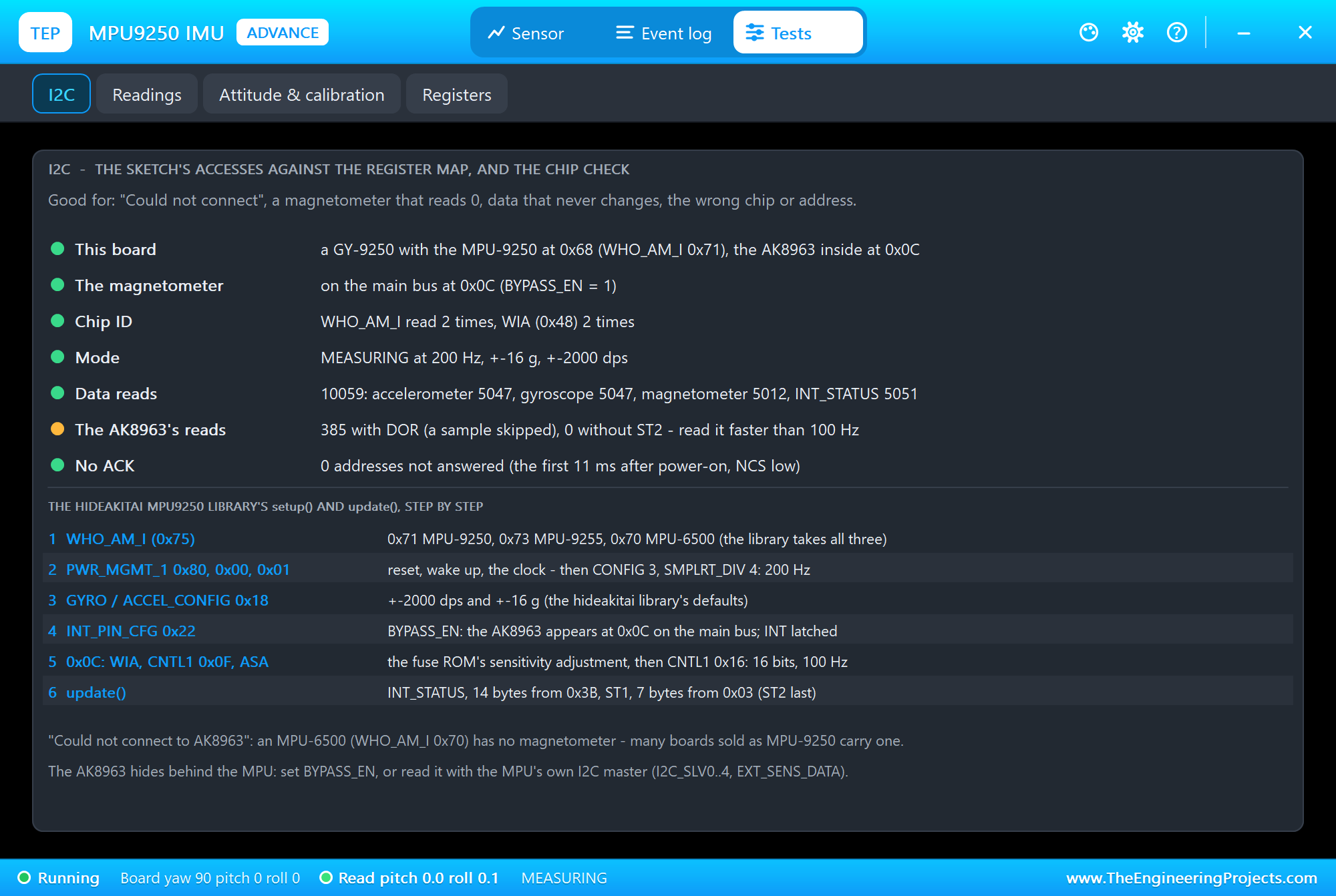
The I2C tool is the one to open for "Could not connect", a magnetometer that reads 0, data that never changes or the wrong address. It names the board and its chip, says where the AK8963 is, counts the calls to 0x0C while it is hidden, the other MPU address, the ID reads and the data reads, the skipped magnetometer samples and the reads without ST2, and shows the library's setup() and update() step by step. In our run it counted 385 magnetometer reads with DOR, a skipped sample now and then, so it shows that line in amber. The Readings tool lists the last 24 transactions:
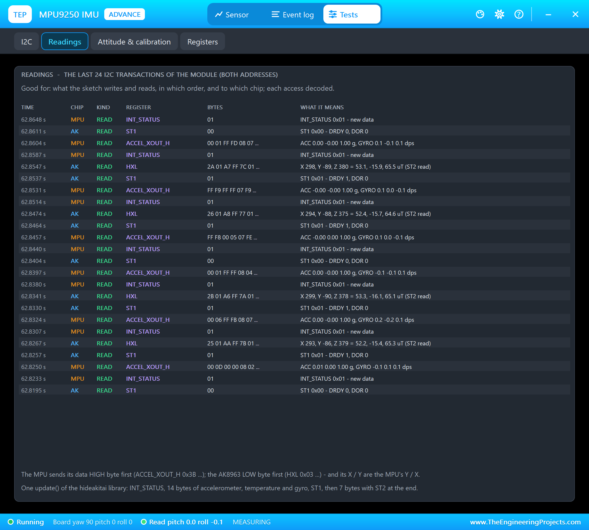
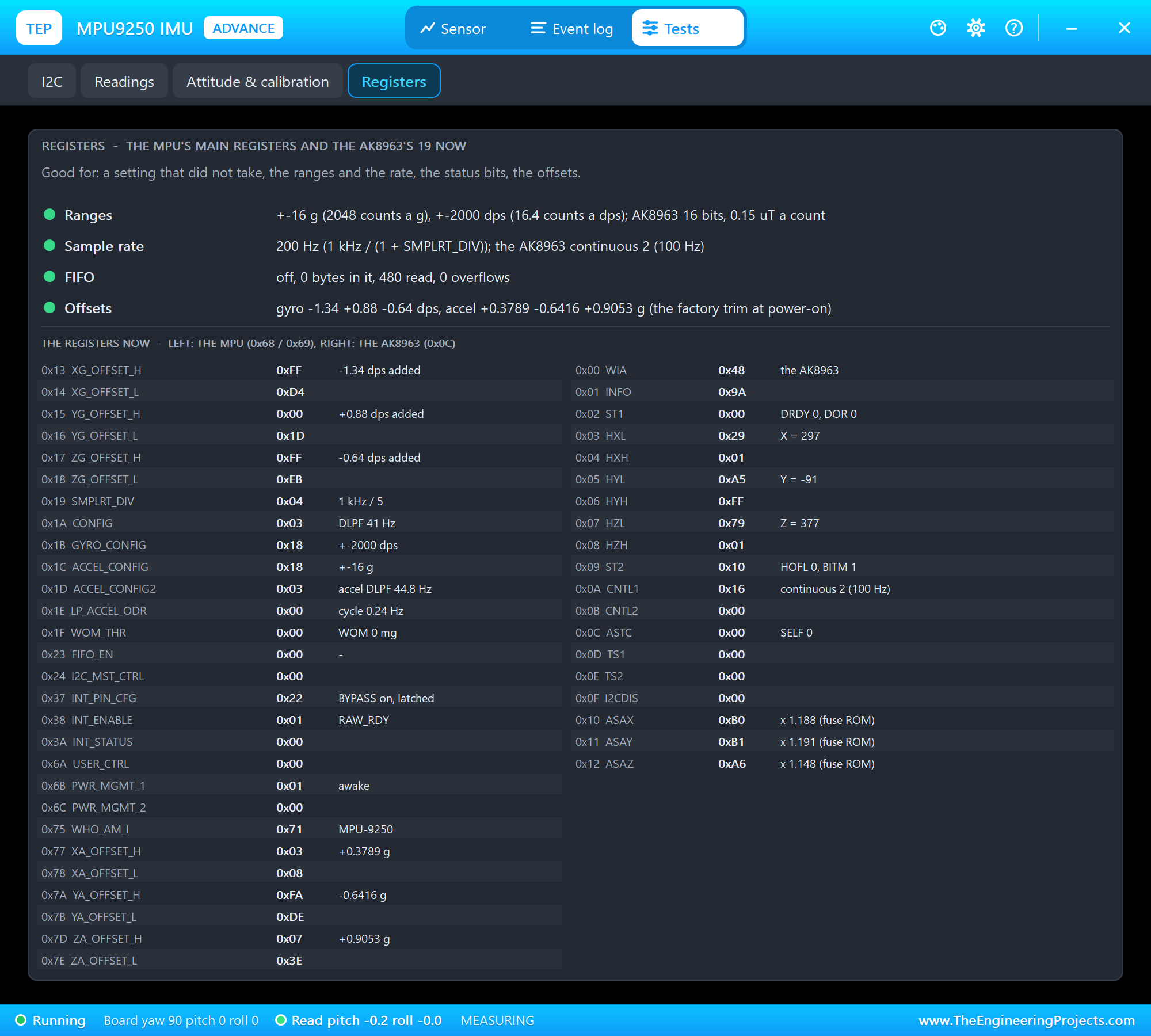
One update() is four reads: INT_STATUS, 14 bytes from 0x3B with the accelerometer, the temperature and the gyro, ST1, and 7 bytes from 0x03 with ST2 at the end. The Registers tool decodes the settings:
The Event Log
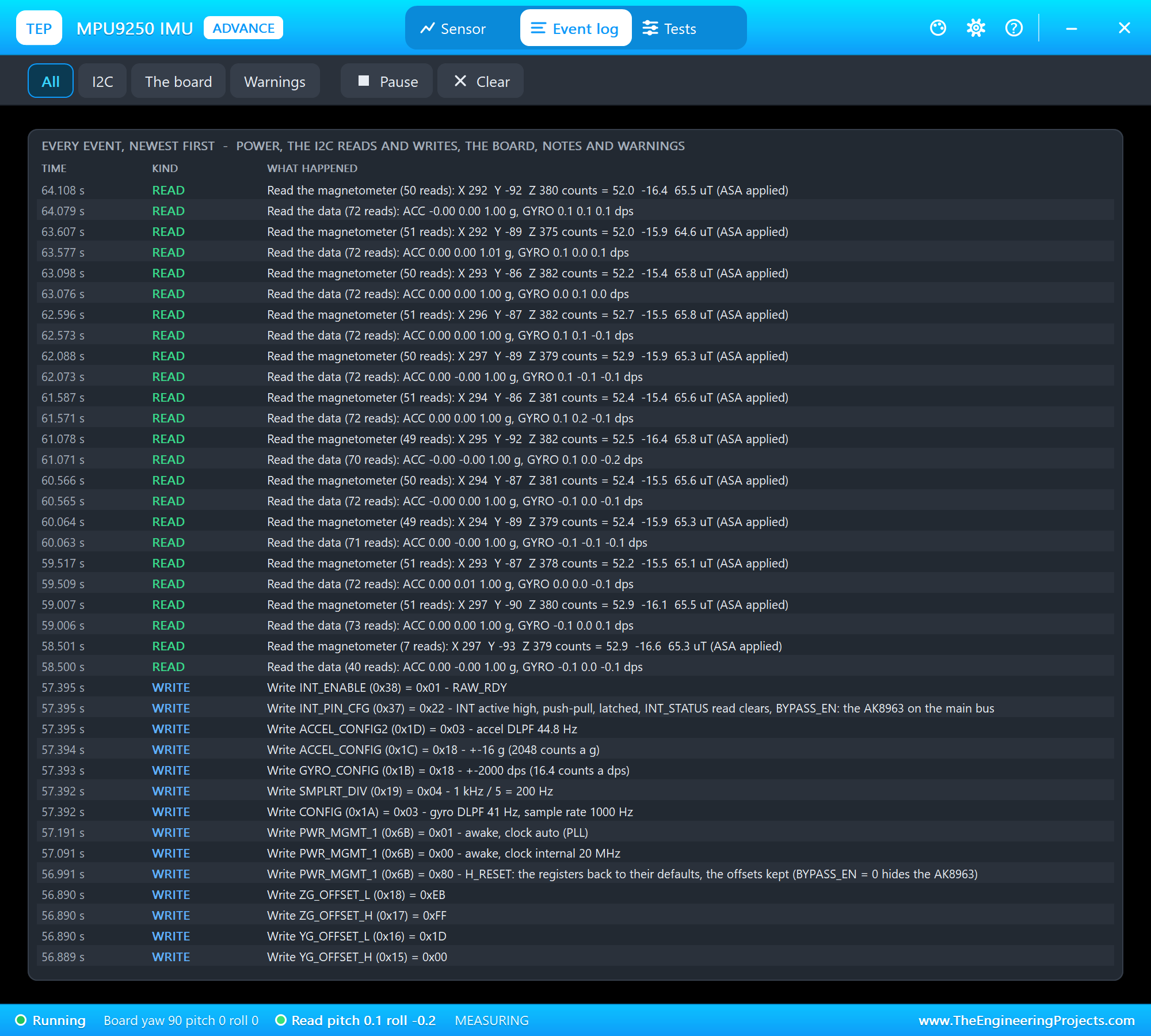
The Event log lists everything that happened, newest first: the power, the register writes of both chips, the data reads, the changes to the board with where they came from, notes and warnings. Filter it by I2C, the board or warnings, pause it, or clear it. Here you can see that the library sets the MPU up again after CALIB, starting with a reset; the model keeps the offset registers through that reset, so the calibration stays.
The Simulation Log
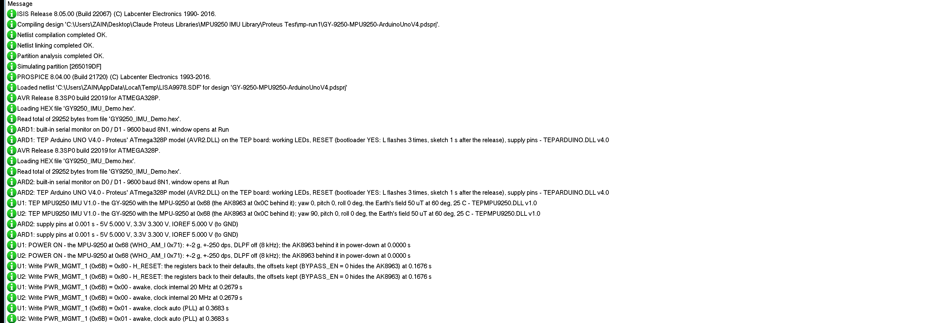
The modules also write to the simulation log of Proteus, with the exact simulation time. This part shows the start of node 1:
U1: TEP MPU9250 IMU V1.0 - the GY-9250 with the MPU-9250 at 0x68 (the AK8963 at 0x0C behind it); yaw 0, pitch 0, roll 0 deg, the Earth's field 50 uT at 60 deg, 25 C - TEPMPU9250.DLL v1.0
U1: POWER ON - the MPU-9250 at 0x68 (WHO_AM_I 0x71): +-2 g, +-250 dps, DLPF off (8 kHz); the AK8963 behind it in power-down at 0.0000 s
U1: Write PWR_MGMT_1 (0x6B) = 0x80 - H_RESET: the registers back to their defaults, the offsets kept (BYPASS_EN = 0 hides the AK8963) at 0.1676 s
U1: Write PWR_MGMT_1 (0x6B) = 0x00 - awake, clock internal 20 MHz at 0.2679 s
U1: Write PWR_MGMT_1 (0x6B) = 0x01 - awake, clock auto (PLL) at 0.3683 s
The library's setup() resets the MPU, wakes it and picks the clock; each write is decoded. The reset clears BYPASS_EN, so the AK8963 is hidden until setup() sets it again a little later.
How the Model Works
The module is a digital model. VCC and GND power it, and SCL and SDA are the I2C bus: Proteus runs every edge from the Arduino with its exact time, and the model answers as two chips - the MPU at its address, and the AK8963 at 0x0C only while the bypass is on. At its sample rate the MPU takes a sample from the board's attitude: gravity and the rotation turned into its axes, with its own small offsets and noise. The AK8963 measures the Earth's field, the magnet and its own offset on its own axes, 100 times a second. The INT pin changes at the simulation time of each sample.
Troubleshooting
- "setup() failed:" and "no MPU at 0x68": no power on VCC and GND, SDA and SCL swapped or missing, AD0 high (the MPU is at 0x69) or NCS low; the PWR LED is off or the I2C LED never flashes.
- "setup() failed:" and WHO_AM_I 0x70: an MPU-6500 - no magnetometer inside.
- The magnetometer reads 0 or never changes: the loop calls update() too slowly (DOR), the AK8963 is still behind the MPU (BYPASS_EN = 0), or its data was read without ST2.
- The yaw is off by tens of degrees: a magnet or steel near the board - run CALMAG while it turns every way; and set your declination, the library starts at -7.51.
- The angles drift slowly: the gyro's bias - run CALIB with the board still.
- No part or no monitor: TEPMPU9250.DLL or TEPARDUINO.DLL is missing from MODELS and the project folder; a closed monitor opens again with a click on the UNO's USB port.
Things to Know Before Using a Real GY-9250
- Check the chip first: MP92 is an MPU-9250, MP65 an MPU-6500 without a magnetometer; or read WHO_AM_I (0x71 or 0x70).
- Keep it away from iron: magnets, motors, speakers and steel screws all pull the yaw.
- Calibrate where it is mounted: CALMAG with a figure eight, CALIB with the board still and flat - the offsets are lost at power-off, so store them and set them again at start-up.
- Keep the loop fast: the hideakitai library needs update() faster than 100 times a second for the magnetometer.
- Set your declination for true north.
Limitations of the Simulation
- Not modelled: SPI (NCS low only stops I2C), the DMP, FSYNC and the AK8963's external trigger, the DLPF's delay (only its effect on the noise), linear acceleration (the board turns about the chip), soft iron, the chips' scale errors, cross-axis sensitivity and temperature drift, and the clock stretching. The world is simple: one fixed field, one magnet, smooth turns.
- The LEDs, the badge, the panel button and the panels are TEP additions.
- The model is our own, written from the MPU-9250 and AK8963 datasheets and register maps. This library is not made or endorsed by InvenSense, TDK, AKM, hideakitai, the makers of the GY-9250 module or Labcenter.
- Licences: the demo sketch uses the MPU9250 library 0.4.8 by hideakitai (MIT), which is not shipped; install it from the Library Manager. The demo's HEX file contains it and the Arduino AVR core 1.8.6 with LGPL-licensed code; the licence texts and the source links are in the README.
- Tested in Proteus 8.5 in October 2026 (the demo as shipped on two Arduino UNO V4.0 boards with their built-in monitors: E, the pitch buttons and ROTATE 360 on node 1 with the mouse, the red X and PANEL; the pitch and roll steps, FLAT, RAW, ROTATE 360, MAGNET, CALMAG with FIGURE 8, CALIB and WHO on node 2, the four tools; a second run with an MPU-6500; 98.9 s of simulation took 314 s, about 0.3 x real time with the pop-up and both monitors open). Proteus 7 is not supported.
So, that was all about the MPU9250 Library for Proteus V1.0. I hope the nine axes, the bypass and the calibrations are clear now, and that your drone or robot knows its attitude from the first run. If you use the MPU9250 Library for Proteus in a project, please share it in the comments or in our forum, and if you have any questions, ask in the comments and I will help you out. Till the next tutorial, take care and have fun!
Comments
0