


PN532 NFC Proteus Library | Arduino NFC RFID Simulation


Hello friends, I hope you are doing well. In today's tutorial, I am going to share our PN532 NFC Proteus Library. With this library, we can place the PN532 NFC RFID module in Proteus and connect it to an Arduino Uno through I2C or through SPI. A control panel beside the module holds four cards. We place a card on the reader with one click, and the Arduino prints its UID and its stored data on the Virtual Terminal.
We will start with the basics of the PN532 and of the two card types used here, which are the MIFARE Classic 1K and the NTAG213. Then we will install the library files, wire the circuit and run the supplied simulations. After that, we will study the control panel in detail and try its cards one by one. We will also understand the Arduino sketch and decode the bytes shown on the terminal. The download includes two wired projects, two compiled HEX files, both sketches and the Arduino driver.
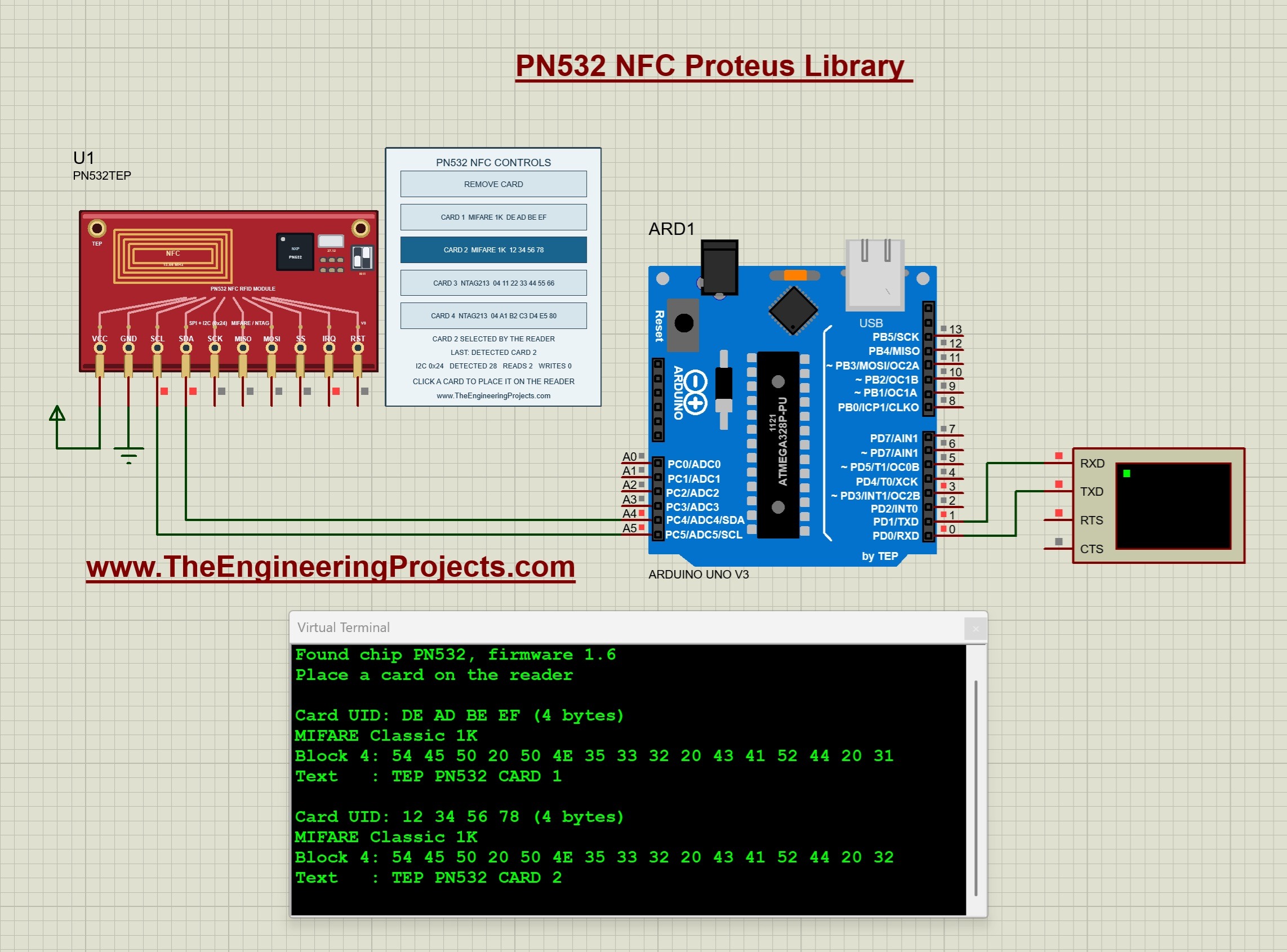
This tutorial uses our V1.0 package, the TEP Arduino UNO V3 and a 16 MHz clock. The package notes record a test of both supplied projects in Proteus 8.5 SP0. The running screenshot below shows the I2C project. CARD 1 and CARD 2 were placed on the reader one after the other, and the terminal shows the UID and block 4 of both cards. On the panel, CARD 2 is highlighted and selected by the reader.
What Is the PN532 NFC Module?
The PN532 is an NFC controller from NXP for the frequency of 13.56 MHz. NFC means near field communication. It is a short-range radio technology that reads and writes contactless cards and tags. The PN532 module carries the chip, a crystal and an antenna on its board. The chip has its own firmware, so the microcontroller does not control the radio directly. It sends commands to the chip and receives the answers.
Main Features of the PN532 Module
- It works at 13.56 MHz, the frequency of NFC and of MIFARE cards.
- It reads and writes cards of the standard ISO/IEC 14443 type A, such as the MIFARE Classic and the NTAG series.
- It offers three host interfaces, which are SPI, I2C and a serial interface called HSU.
- Two small switches on the board select the interface.
- Its I2C address is 0x24.
- Its IRQ pin tells the microcontroller that an answer is ready.
- Its reset pin is named RSTPDN and is active low.
The Two Card Types of This Tutorial
| Property | MIFARE Classic 1K | NTAG213 |
|---|---|---|
| Length of the UID | 4 bytes | 7 bytes |
| Memory unit | Block of 16 bytes | Page of 4 bytes |
| Size of the memory | 64 blocks in 16 sectors, 1024 bytes | 45 pages, 180 bytes |
| Memory for user data | 47 data blocks, 752 bytes | Pages 4 to 39, 144 bytes |
| Protection | Two keys and access bits for every sector | Readable without a key |
| Typical use | Access cards and tickets | NFC tags with a link for a phone |
Important Terms
- UID: the unique identifier of a card. It is the number that most access projects compare.
- Block and sector: a MIFARE Classic card stores its data in blocks of 16 bytes. Four blocks form one sector.
- Sector trailer: the last block of every sector. It holds key A, the access bits and key B of this sector.
- Authentication: the proof that the reader knows a key of the sector. A sector can be read only after it.
- Page: the memory unit of an NTAG card. One page has 4 bytes.
- NDEF: the data format of NFC tags. A phone reads an NDEF message without a special application.
- URI record: an NDEF record that holds a web address.
Features of Our Proteus Model
- The component is named PN532TEP and has ten pins.
- It answers on SPI and on I2C, so the same component works in both supplied projects.
- A control panel beside the module holds four cards and a REMOVE CARD button.
- The panel shows the state of the reader, the last operation and three counters.
- Two cards are MIFARE Classic 1K cards with sector keys and access bits.
- Two cards are NTAG213 tags, and one of them carries an NDEF message with a web address.
- The UID of every card can be changed in the properties of the component.
- The Arduino communicates with the model through the real frames of the PN532, so the unmodified Arduino driver works with it.
Keep one distinction in mind. This is a functional model of the reader and of its cards. It does not simulate the radio field, the distance of a card or two cards at the same time. A card is either on the reader or not.
Download the PN532 NFC Library for Proteus
First of all, download the V1.0 package using the button below. Extract the complete ZIP into a normal folder before opening a project, and keep the files of the simulation folder together.
Download PN532 NFC Proteus Library V1.0 and Arduino Simulation| Folder or file | Contents and purpose |
|---|---|
| Proteus Library Files | TEPPN532.LIB for the NFC module, and the TEP Arduino UNO V3 LIB/IDX files. |
| Proteus Model Files | TEPPN532.DLL, which provides the simulated behavior of the reader and its cards. |
| Proteus Simulation | PN532-I2C-ArduinoUnoV3.pdsprj, PN532-SPI-ArduinoUnoV3.pdsprj, both HEX files and a local copy of the DLL. |
| Arduino Code | Both sketches, the Adafruit PN532 1.3.4 and Adafruit BusIO 1.17.4 libraries, the AVR core archive and a firmware rebuild script. |
| Model Source | The chip and card model, the SPI and I2C transports and the Proteus adapter. |
| Documentation | Model notes, third-party notices and a preview of the board artwork. |
| README.txt and SHA256SUMS.txt | Quick-start instructions and checksums of the packaged files. |
The Proteus library and the Arduino library have different jobs. The LIB file defines the component that we place on the schematic, and the DLL gives it its behavior. The Adafruit PN532 library gives our sketch the functions for talking to the reader. Installing the Arduino library alone will not make PN532TEP appear in Proteus.
How to Install the PN532 Library in Proteus
Copy the Library and Model Files
Save your work and close Proteus before copying the files. Then follow these steps:
- Open the extracted Proteus Library Files folder.
- Copy
TEPPN532.LIBinto the library directory configured for your Proteus installation. - Copy
ArduinoV3TEP.LIBandArduinoV3TEP.IDXfrom the same folder if our TEP Arduino UNO V3 library is not installed already. - Open Proteus Model Files and copy
TEPPN532.DLLinto your configured ProteusMODELSdirectory. - Restart Proteus, open Pick Devices and search for PN532TEP.
- Place the module on the schematic, or open one of the supplied projects to use a completed circuit.
Points to Remember
- Use the library and model folders that your installation actually searches. Their locations differ between installations.
- The module is supplied as a LIB file without a separate IDX. The included IDX belongs to the Arduino board.
- Keep the extra DLL beside the projects in the Proteus Simulation folder.
- The two HEX files are programs for the Arduino. The NFC module does not need a HEX file.
- Each project uses one HEX file. The I2C project needs PN532_I2C_Demo.hex, and the SPI project needs PN532_SPI_Demo.hex.
- Compatibility with Proteus 7 has not been established.
The Arduino board in these projects comes from our Arduino Library for Proteus V3.0. Start with a supplied project, so that the board, wiring and firmware match the demonstration.
PN532 Pinout and Arduino Uno Wiring
The TEP module has ten pins along its lower edge. From left to right, they are VCC, GND, SCL, SDA, SCK, MISO, MOSI, SS, IRQ and RST. A real board has two separate headers for I2C and SPI. Our component shows both of them in one row. Start each wire at the exposed pin endpoint below the board artwork.
| Module pin | I2C project | SPI project | Purpose |
|---|---|---|---|
| VCC | Positive supply terminal | Positive supply terminal | Powers the digital model. |
| GND | Ground | Ground | Provides the shared reference. |
| SCL | Arduino Uno A5 | Not used | I2C clock from the Arduino. |
| SDA | Arduino Uno A4 | Not used | I2C data in both directions. |
| SCK | Not used | Arduino Uno D13 | SPI clock from the Arduino. |
| MISO | Not used | Arduino Uno D12 | Data from the module to the Arduino. |
| MOSI | Not used | Arduino Uno D11 | Data from the Arduino to the module. |
| SS | Not used | Arduino Uno D10 | Selects the module for an SPI transfer. It is active low. |
| IRQ | Optional, Arduino Uno D2 | Not needed | Goes low while an answer is ready. |
| RST | Optional, Arduino Uno D3 | Not needed | Reset input RSTPDN. It is active low. |
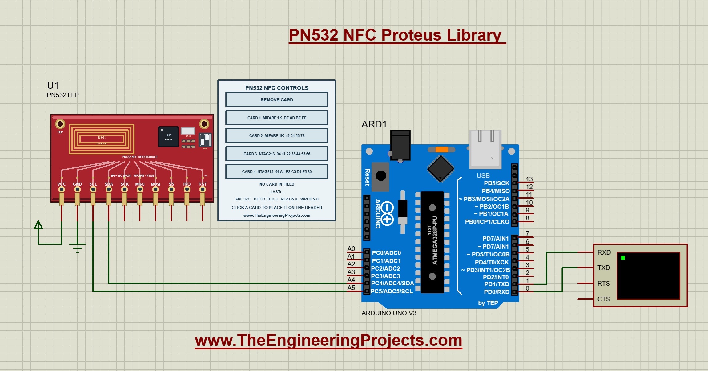
The picture shows the stopped I2C project. Only four pins of the module are connected, which are VCC, GND, SCL and SDA. The panel shows the four cards, the state NO CARD IN FIELD and three counters at zero.
Wire the I2C Project
- Connect VCC to the supply terminal and GND to the ground terminal.
- Connect SDA of the module to A4 of the Arduino Uno.
- Connect SCL of the module to A5 of the Arduino Uno.
- Leave the other pins open. The driver asks the chip through I2C whether an answer is ready, so the IRQ wire is optional.
Wire the SPI Project
- Connect VCC to the supply terminal and GND to the ground terminal.
- Connect SCK to D13, MISO to D12 and MOSI to D11.
- Connect SS to D10.
- IRQ and RST are not needed for this project.
Virtual Terminal Connections
- Connect Arduino D1/TX to RXD on the Virtual Terminal.
- Set the terminal to 9600 baud, eight data bits, no parity and one stop bit.
- The lines of the demo are long. Drag the border of the terminal window to make it wider.
Notes for Physical Hardware
- Set the mode switches of your board. On boards of the Elechouse V3 style, SPI needs I0 off and I1 on, and I2C needs I0 on and I1 off.
- Other boards use jumpers instead of switches. Check the documentation of your board.
- Check the supply range of your board. Boards of the Elechouse V3 style accept 3.3 to 5 V.
- The model does not check the supply voltage, so a working simulation does not prove that your hardware supply is correct.
- An I2C bus needs pull-up resistors on SDA and SCL. Check whether your board already carries them.
- The order of the pins differs between boards. Follow the printed names on your module and not the order of our component.
In the simulation, the switches do not have to be set. Both interfaces of the model are active at the same time. The model answers on SPI when SS is used, and it answers on I2C at the address 0x24.
Run the PN532 Simulation
Start the Simulation
- Open
Proteus Simulation/PN532-I2C-ArduinoUnoV3.pdsprjorPN532-SPI-ArduinoUnoV3.pdsprjfrom the extracted package. - Keep both HEX files and
TEPPN532.DLLin that folder. - Double-click ARD1 and confirm its Program File. It is
PN532_I2C_Demo.hexin the I2C project andPN532_SPI_Demo.hexin the SPI project. - Confirm the 16 MHz clock of the board and 9600 baud on the terminal.
- Press Run and wait for the line Place a card on the reader.
- Click a card on the panel. Click REMOVE CARD to take it away.
If you have closed the terminal window, open it again from the Debug menu while the simulation runs.
Read the Terminal Output
- The first line is the title of the demo. It ends with (I2C) or (SPI).
- The second line is Found chip PN532, firmware 1.6. It proves that the Arduino and the module understand each other.
- The third line is Place a card on the reader.
- For every new card, the demo prints an empty line, the UID with its length and the type of the card.
- For a MIFARE Classic card, it prints block 4 as 16 hexadecimal bytes and as text.
- For an NTAG card, it prints the pages 4 to 7 and the web address of the NDEF message.
- When the card is taken away, the demo prints Card removed.
In the running screenshot at the top, the first report belongs to CARD 1 with the UID DE AD BE EF. Its block 4 holds the text TEP PN532 CARD 1. The second report belongs to CARD 2 with the UID 12 34 56 78 and the text TEP PN532 CARD 2. There is no Card removed line between them, because CARD 2 was clicked while CARD 1 was still on the reader.
Read the Simulation Log
The model also writes short messages into the Simulation Log of Proteus. Each message starts with TEP PN532 and the name of the module, such as U1.
| Message | Meaning |
|---|---|
| model started, with the firmware version and the card types | The model has been loaded for this component. |
| powered | The model accepts the VCC and GND connections. |
| NOT powered (check VCC/GND) | VCC is low or GND is high. |
| host talks SPI, or host talks I2C at address 0x24 | The interface that the Arduino uses. |
| a card with its type and UID placed on the reader | A card button was clicked. |
| card removed | REMOVE CARD was clicked. |
| first card detected | The reader has found a card for the first time. |
| MIFARE authentication failed | A sketch used a wrong key for a sector. |
| RSTPDN low | The reset pin was pulled low. |
Understand the PN532 Control Panel
The control panel is the most interesting part of this library. It replaces the hand that holds a card over the reader, and it shows what the reader is doing with this card. The following picture shows the module and its panel while CARD 2 lies on the reader.
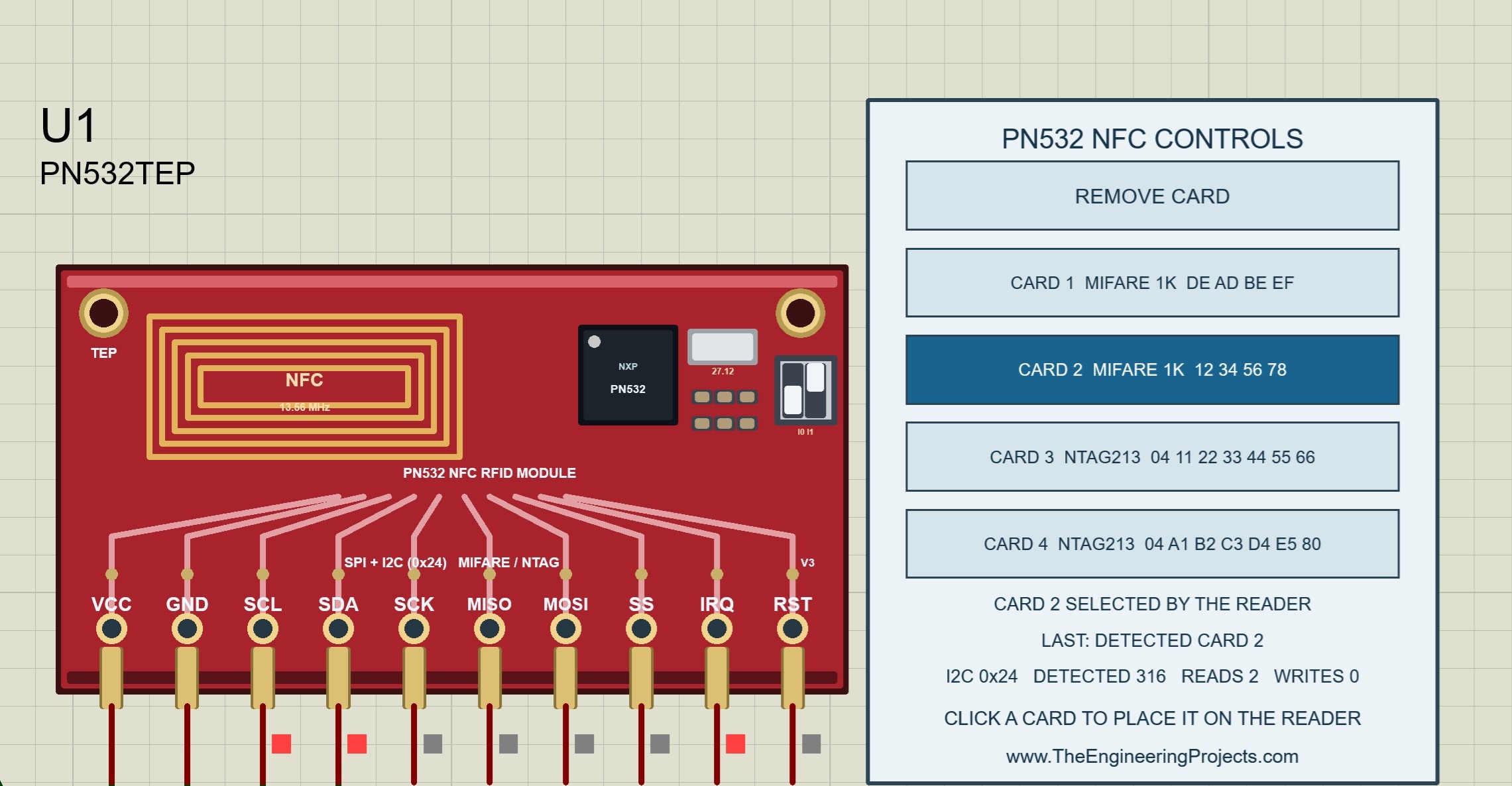
The title of the panel is PN532 NFC CONTROLS. Let us go through the panel from top to bottom.
The Five Buttons
| Button | Card type | UID | Stored data |
|---|---|---|---|
| REMOVE CARD | None | None | Takes the card away from the reader. |
| CARD 1 | MIFARE Classic 1K | DE AD BE EF | Block 4 holds the text TEP PN532 CARD 1. |
| CARD 2 | MIFARE Classic 1K | 12 34 56 78 | Block 4 holds the text TEP PN532 CARD 2. |
| CARD 3 | NTAG213 | 04 11 22 33 44 55 66 | An NDEF message with the address https://www.theengineeringprojects.com. |
| CARD 4 | NTAG213 | 04 A1 B2 C3 D4 E5 80 | An empty NDEF message. |
- Every card button shows the number of the card, its type and its UID.
- The card that lies on the reader is highlighted in dark blue.
- Only one card can lie on the reader. A click on another card replaces the present one.
- A second click on the highlighted card changes nothing.
The State Line
The first line below the buttons shows the state of the reader and of the card.
| State | Meaning |
|---|---|
| NO CARD IN FIELD | No card lies on the reader, and the reader is not searching. |
| WAITING FOR A CARD... | The sketch has asked for a card, and the reader is searching. |
| CARD 2 IN FIELD - DETECTING... | A card was placed while the reader was searching. The reader is reading its UID. |
| CARD 2 SELECTED BY THE READER | The reader has found the card and selected it. The card now accepts commands. |
| CARD 2 IN FIELD | The card lies on the reader, but it is not selected. |
| IN RESET - RSTPDN LOW | The RST pin is low, so the chip is held in reset. |
| NO POWER - CHECK VCC / GND | The module is not powered. |
With the supplied sketches, you will mostly see two of these states. Without a card, the sketch asks for a card again and again, so the panel shows WAITING FOR A CARD. With a card, the panel shows that the card is selected by the reader, as in the picture above. The state CARD 2 IN FIELD appears when a card lies on the reader while no sketch asks for it, or after a failed authentication.
The LAST Line
The second line shows the last operation of the reader. Before the first operation, it shows a dash.
| Text | Meaning |
|---|---|
| DETECTED CARD 2 | The reader has found CARD 2 and read its UID. |
| AUTH BLOCK 4 KEY A OK | The key A of the sketch fits the sector of block 4. |
| AUTH BLOCK 4 KEY A FAILED | The key A of the sketch is wrong. |
| READ BLOCK 4 OK | Block 4 of a MIFARE card was read. |
| WRITE BLOCK 4 OK | Block 4 of a MIFARE card was written. |
| BLOCK 8 NOT AUTHENTICATED | The sketch used block 8 without an authentication for its sector. |
| BLOCK 0 IS READ-ONLY | The sketch tried to write the manufacturer block. |
| READ PAGE 4 OK | Page 4 of an NTAG card was read. |
| WRITE PAGE 5 OK | Page 5 of an NTAG card was written. |
| NO ANSWER (NO CARD) | The sketch sent a card command, but no card lies on the reader. |
In our pictures, the line shows DETECTED CARD 2, although the sketch has read block 4 of this card. The reason is the sketch. It reads the block only once, but it keeps checking whether the card is still there. Every check is a new detection, so the detection is always the last operation.
The Counters Line
- The interface is shown first. Before the Arduino has sent anything, the line shows SPI / I2C. After that, it shows SPI or I2C 0x24.
- DETECTED counts the detections of a card.
- READS counts the blocks and pages that were read.
- WRITES counts the blocks and pages that were written.
- AUTH FAIL appears at the end of the line after the first failed authentication.
In the running screenshot, the line shows I2C 0x24, DETECTED 28, READS 2 and WRITES 0. The two reads are block 4 of CARD 1 and block 4 of CARD 2. In the close-up picture, which was taken later, the detections have grown to 316, and the reads are still 2.
Panel Combinations: Cards, Clicks and Counters
Now comes the exciting part. We will try the buttons in different orders and watch the terminal, the state line and the counters. The reports of CARD 1 and CARD 2 agree with the screenshots of this tutorial. The package notes record the reports of CARD 3 and CARD 4 and the Card removed line as tested in Proteus. The counter values of the other cases follow from the rules of the model and of the sketch.
Combination 1: Place, Replace and Remove a Card
| Click | Card on the reader before | Terminal | State line |
|---|---|---|---|
| CARD 1 | None | Report of CARD 1 | CARD 1 SELECTED BY THE READER |
| CARD 1 again | CARD 1 | Nothing new | CARD 1 SELECTED BY THE READER |
| CARD 2 | CARD 1 | Report of CARD 2, without Card removed | CARD 2 SELECTED BY THE READER |
| REMOVE CARD | CARD 2 | Card removed | WAITING FOR A CARD... |
| CARD 2 | None | Report of CARD 2 again | CARD 2 SELECTED BY THE READER |
- The sketch reports a card once, as long as it stays on the reader.
- The sketch compares the UID with the UID of the last card. A different UID counts as a new card.
- To read the same card again, remove it and place it again.
- If a card button is still highlighted when you press Run, the model places this card on the reader at the start.
Combination 2: The Four Cards and Their Reports
| Card | UID line | Type line | Data lines |
|---|---|---|---|
| CARD 1 | DE AD BE EF (4 bytes) | MIFARE Classic 1K | Block 4 and the text TEP PN532 CARD 1 |
| CARD 2 | 12 34 56 78 (4 bytes) | MIFARE Classic 1K | Block 4 and the text TEP PN532 CARD 2 |
| CARD 3 | 04 11 22 33 44 55 66 (7 bytes) | NTAG2xx / Ultralight | Pages 4-7 and NDEF URI: https://www.theengineeringprojects.com |
| CARD 4 | 04 A1 B2 C3 D4 E5 80 (7 bytes) | NTAG2xx / Ultralight | Pages 4-7 and NDEF: empty message |
The sketch decides by the length of the UID. A UID of 4 bytes is treated as a MIFARE Classic card, and a UID of 7 bytes is treated as an NTAG card. For CARD 3, the line of the pages 4 to 7 reads 01 03 A0 10 44 03 1F D1 01 1B 55 02 74 68 65 65. We will decode these bytes after the code.
Combination 3: The Counters for Every Card Type
| Event | DETECTED | READS | WRITES |
|---|---|---|---|
| A MIFARE card is placed and reported. | Plus 1 | Plus 1, for block 4 | No change |
| An NTAG card is placed and reported. | Plus 1 | Plus 12, for the pages 4 to 15 | No change |
| A card stays on the reader. | About four to five per second | No change | No change |
| No card lies on the reader. | No change | No change | No change |
- The READS counter tells us how many cards were reported. After CARD 1 and CARD 2, it shows 2. After CARD 3 in addition, it shows 14.
- The DETECTED counter grows as long as a card lies on the reader. The sketch waits 200 ms after every check of the same card, which gives the rate of the table.
- The WRITES counter stays at zero, because the demo only reads. It changes as soon as your own sketch writes a block or a page.
Combination 4: Keys and Authentication
A MIFARE Classic card protects every sector with two keys. The cards of the model start in the factory configuration, in which both keys are FF FF FF FF FF FF. The demo uses this key A for block 4. With your own sketch, you can test the other cases.
| Case | Result in the model | Panel |
|---|---|---|
| Right key A for the sector of block 4 | The blocks 4 to 7 can be used. | AUTH BLOCK 4 KEY A OK |
| Wrong key A | The card leaves the selected state and must be detected again. | AUTH BLOCK 4 KEY A FAILED and AUTH FAIL |
| Block 8 after an authentication for block 4 | The access is refused, because block 8 belongs to another sector. | BLOCK 8 NOT AUTHENTICATED |
| Key B in the factory configuration | The authentication succeeds, but every access after it is refused. | BLOCK 4 ACCESS DENIED |
| A new detection of the card | The earlier authentication is lost. | DETECTED CARD 1 |
The fourth case is a rule of the real card. In the factory configuration, key B can be read from the sector trailer, and a key that can be read cannot protect anything. The last case explains the order of the sketch, which authenticates the block directly after the detection of the card.
Combination 5: Write to a Card and Read It Again
- The driver function
mifareclassic_WriteDataBlock()writes 16 bytes into a block of a MIFARE card. The block must be authenticated first. - The driver function
ntag2xx_WritePage()writes 4 bytes into a page of an NTAG card. It accepts the pages from 4 upwards. - Every successful write increases the WRITES counter, and the LAST line shows the block or the page.
- Block 0 of a MIFARE card holds the UID and cannot be written.
- The written data stay on the card while the simulation runs. You can remove the card, place another one and place the first card again.
- Every new Run starts with fresh cards, so a mistake with a key or an access bit cannot damage a card for ever.
The last point is an advantage of the simulation. On a real MIFARE card, wrong access bits can lock a sector permanently. In Proteus, you stop the simulation and start again.
Combination 6: I2C and SPI
| Property | I2C project | SPI project |
|---|---|---|
| Wires to the Arduino | 2, which are SDA and SCL | 4, which are SCK, MISO, MOSI and SS |
| Arduino pins | A4 and A5 | D10 to D13 |
| Address or selection | Address 0x24 | SS low |
| Bit order | Most significant bit first | Least significant bit first |
| Counters line of the panel | I2C 0x24 | SPI |
| Title line on the terminal | Ends with (I2C) | Ends with (SPI) |
| Reports of the cards | The same | The same |
The cards and the panel behave in the same way with both interfaces. Use I2C when you want to save pins, and use SPI when the I2C bus of your project is occupied or when you need the pins A4 and A5 as analog inputs.
Combination 7: Your Own Cards
The four UIDs are properties of the component. Stop the simulation, open the properties of the module and edit UID1 to UID4.
| Entry | Result |
|---|---|
| 8 hexadecimal digits, such as A1B2C3D4 | A MIFARE Classic 1K card with a UID of 4 bytes. |
| 14 hexadecimal digits, such as 04AABBCCDDEE80 | An NTAG213 card with a UID of 7 bytes. |
| Any other length, or other characters | The model uses the default UID of this card. |
- The button of the card shows the new type and the new UID.
- A MIFARE card always carries the text TEP PN532 CARD with its number in block 4.
- An NTAG card on the first or the third button carries the web address. On the second or the fourth button, it carries the empty NDEF message.
With these properties, you can simulate the cards of your own project. Enter the UID of your real card, and your access control sketch will see the same number in Proteus.
Arduino Code for the PN532 I2C Demo
The following is the exact I2C sketch included in the download. It uses the bundled Adafruit PN532 library, version 1.3.4, together with Adafruit BusIO 1.17.4. Use the supplied copies for your first build, so that your firmware matches the packaged HEX file.
// TEP PN532 NFC Demo v1.0 (I2C)
// The Engineering Projects - www.TheEngineeringProjects.com
//
// Reads ISO14443A cards and tags with the PN532 and reports each card once while it
// stays on the reader (then "Card removed"):
//   MIFARE Classic 1K (4-byte UID): block 4 with the factory key A FF FF FF FF FF FF
//   NTAG213 / Ultralight (7-byte UID): pages 4..15 and an NDEF URI record, if any
//
// Wiring (Arduino UNO, I2C address 0x24): VCC -> 5V, GND -> GND, SDA -> A4, SCL -> A5
// IRQ -> D2 and RSTPDN -> D3 are optional: the library polls the ready byte over I2C.
// Real module: set the mode switches to I2C (Elechouse V3: I0 = ON, I1 = OFF).
// Library: Adafruit PN532 (Arduino Library Manager: "Adafruit PN532", installs Adafruit BusIO)

#include <Wire.h>
#include <Adafruit_PN532.h>

#define TITLE "TEP PN532 NFC Demo v1.0 (I2C)"
#define PN532_IRQ   2
#define PN532_RESET 3
Adafruit_PN532 nfc(PN532_IRQ, PN532_RESET);  // I2C
void readClassic(uint8_t *uid, uint8_t uidLength);
void readNtag();

uint8_t lastUid[7];
uint8_t lastUidLength = 0;                 // 0 = no card on the reader

void printHexBytes(const uint8_t *data, uint8_t length) {
  for (uint8_t i = 0; i < length; i++) {
    if (data[i] < 0x10) Serial.print('0');
    Serial.print(data[i], HEX);
    Serial.print(' ');
  }
}

void setup() {
  Serial.begin(9600);
  Serial.println(F(TITLE));
  nfc.begin();
  uint32_t version = nfc.getFirmwareVersion();
  if (!version) {
    Serial.println(F("PN532 not found - check the wiring and the mode switches"));
    while (true) {}
  }
  Serial.print(F("Found chip PN5"));
  Serial.print((version >> 24) & 0xFF, HEX);
  Serial.print(F(", firmware "));
  Serial.print((version >> 16) & 0xFF);
  Serial.print('.');
  Serial.println((version >> 8) & 0xFF);
  nfc.setPassiveActivationRetries(0x10);   // give up after a few tries, so a removed card is noticed
  Serial.println(F("Place a card on the reader"));
}

void loop() {
  uint8_t uid[7], uidLength;
  if (!nfc.readPassiveTargetID(PN532_MIFARE_ISO14443A, uid, &uidLength)) {
    if (lastUidLength) {
      Serial.println(F("Card removed"));
      lastUidLength = 0;
    }
    return;
  }
  if (uidLength == lastUidLength && memcmp(uid, lastUid, uidLength) == 0) {   // same card still there
    delay(200);
    return;
  }
  memcpy(lastUid, uid, uidLength);
  lastUidLength = uidLength;
  Serial.println();
  Serial.print(F("Card UID: "));
  printHexBytes(uid, uidLength);
  Serial.print('(');
  Serial.print(uidLength);
  Serial.println(F(" bytes)"));
  if (uidLength == 4) readClassic(uid, uidLength);
  else readNtag();
}

// MIFARE Classic 1K: block 4 with the factory key A
void readClassic(uint8_t *uid, uint8_t uidLength) {
  uint8_t keyA[6] = {0xFF, 0xFF, 0xFF, 0xFF, 0xFF, 0xFF};
  uint8_t data[16];
  Serial.println(F("MIFARE Classic 1K"));
  if (!nfc.mifareclassic_AuthenticateBlock(uid, uidLength, 4, 0, keyA)) {
    Serial.println(F("Block 4: authentication failed (key A is not FF..FF)"));
    return;
  }
  if (!nfc.mifareclassic_ReadDataBlock(4, data)) {
    Serial.println(F("Block 4: read failed"));
    return;
  }
  Serial.print(F("Block 4: "));
  printHexBytes(data, 16);
  Serial.println();
  Serial.print(F("Text   : "));
  for (uint8_t i = 0; i < 16; i++) Serial.print(data[i] >= 32 && data[i] < 127 ? (char)data[i] : '.');
  Serial.println();
}

// NTAG213 / Ultralight: pages 4..15 and the first NDEF record
void readNtag() {
  uint8_t data[48];
  Serial.println(F("NTAG2xx / Ultralight"));
  for (uint8_t page = 4; page < 16; page++) {
    if (!nfc.ntag2xx_ReadPage(page, data + (page - 4) * 4)) {
      Serial.println(F("Page read failed"));
      return;
    }
  }
  Serial.print(F("Pages 4-7: "));
  printHexBytes(data, 16);
  Serial.println();
  uint8_t i = 0;
  while (i < sizeof(data) - 1) {                         // walk the TLV blocks
    uint8_t type = data[i];
    if (type == 0x00) { i++; continue; }                  // NULL TLV
    if (type == 0xFE) break;                              // terminator
    uint8_t length = data[i + 1];
    if (type == 0x03) {                                   // NDEF message
      if (length == 0) { Serial.println(F("NDEF: empty message")); return; }
      uint8_t *record = data + i + 2;
      if (record[1] == 1 && record[3] == 'U') {           // short record, type "U" (URI)
        static const char *prefixes[] = {"", "http://www.", "https://www.", "http://", "https://"};
        uint8_t payloadLength = record[2];
        Serial.print(F("NDEF URI: "));
        if (record[4] < 5) Serial.print(prefixes[record[4]]);
        for (uint8_t k = 1; k < payloadLength && 5 + k < sizeof(data) - i - 2; k++) Serial.print((char)record[4 + k]);
        Serial.println();
      } else {
        Serial.println(F("NDEF: record is not a URI"));
      }
      return;
    }
    i += 2 + length;                                      // skip other TLVs (lock control, ...)
  }
  Serial.println(F("No NDEF message"));
}
Create the Reader Object
The line Adafruit_PN532 nfc(PN532_IRQ, PN532_RESET) creates the object for I2C. Its two parameters are the Arduino pins for IRQ and for the reset. In the supplied project, these two wires are not connected. The driver still works, because it reads the ready status of the chip through I2C.
Start the Reader
nfc.begin()starts the interface and wakes the chip. It also sends the SAM configuration command, which keeps the chip in its normal mode.nfc.getFirmwareVersion()asks the chip for its version. The answer is a number of four bytes.- If the answer is zero, the sketch prints PN532 not found and stops.
- The sketch prints the chip and the firmware from the bytes of the answer.
nfc.setPassiveActivationRetries(0x10)limits the search for a card. Without this line, the chip would search for ever, and the sketch could not notice that a card was removed.
Detect a Card
The function nfc.readPassiveTargetID() searches for a card of the type ISO 14443A. It returns the UID and its length. The loop handles three cases:
- No card was found. If a card was there before, the sketch prints Card removed.
- The same card is still there. The sketch waits 200 ms and checks again.
- A new card was found. The sketch stores the UID, prints it and reads the card.
Read a MIFARE Classic Card
nfc.mifareclassic_AuthenticateBlock()proves the key for block 4. Its parameters are the UID, the block number, the key type and the key. The key type 0 means key A.nfc.mifareclassic_ReadDataBlock()reads the 16 bytes of block 4.- The sketch prints the bytes in hexadecimal form.
- The sketch prints the same bytes as text. A byte that is not a printable character is shown as a dot.
Read an NTAG Card
nfc.ntag2xx_ReadPage()reads one page of 4 bytes. The sketch calls it twelve times for the pages 4 to 15, which gives 48 bytes.- The sketch prints the first 16 bytes as the pages 4 to 7.
- The sketch walks through the data and searches for the NDEF message.
- For a URI record, it prints the prefix and the rest of the address.
What Changes in the SPI Sketch
The package contains a second sketch for SPI. Its loop and its two reading functions are the same as above. Only these lines differ:
| Part | I2C sketch | SPI sketch |
|---|---|---|
| Interface library | #include <Wire.h> | #include <SPI.h> |
| Title | TEP PN532 NFC Demo v1.0 (I2C) | TEP PN532 NFC Demo v1.0 (SPI) |
| Pin definitions | PN532_IRQ is 2, and PN532_RESET is 3 | PN532_SS is 10 |
| Reader object | Adafruit_PN532 nfc(PN532_IRQ, PN532_RESET) | Adafruit_PN532 nfc(PN532_SS) |
With one parameter, the driver uses the hardware SPI pins of the Arduino and the given pin as SS. The driver takes care of the bit order of the PN532, which sends the least significant bit first.
More Functions of the Arduino Driver
The demo uses only a few functions of the driver. The package notes list the following functions as tested with the model on a PC. They were not each run in Proteus, so treat them as the next step for your own experiments.
| Function | Purpose |
|---|---|
SAMConfig() | Sets the chip to its normal mode. |
mifareclassic_WriteDataBlock() | Writes a block of a MIFARE Classic card. |
mifareclassic_FormatNDEF() | Prepares sector 0 of a MIFARE Classic card for NDEF. It changes key A of this sector. |
mifareclassic_WriteNDEFURI() | Writes a web address into a sector of a MIFARE Classic card. It changes key A of this sector. |
ntag2xx_WritePage() | Writes a page of an NTAG card. |
ntag2xx_WriteNDEFURI() | Writes a web address into an NTAG card. |
inListPassiveTarget() and inDataExchange() | Select a card and exchange raw data with it. |
startPassiveTargetIDDetection() and readDetectedPassiveTargetID() | Search for a card without blocking the sketch. They use the IRQ pin. |
readGPIO() and writeGPIO() | Use the general purpose pins of the chip. |
Understand the Data on the Terminal
The Firmware Version
The chip of the model answers the version request with the four bytes 32 01 06 07. The sketch takes them apart:
- The first byte is 0x32. The sketch prints it in hexadecimal form behind the text PN5, which gives PN532.
- The second byte is the version 1, and the third byte is the revision 6. Together, they give firmware 1.6.
- The fourth byte describes the supported card standards. The sketch does not print it.
The Frame and Its Checksums
The Arduino and the PN532 exchange their data in frames. Every frame carries two checksums, and we can calculate them by hand. The request for the firmware version is the frame 00 00 FF 02 FE D4 02 2A 00.
| Bytes | Name | Explanation |
|---|---|---|
| 00 00 FF | Preamble and start code | They mark the start of a frame. |
| 02 | Length | Two data bytes follow. |
| FE | Length checksum | 02 + FE = 100 in hexadecimal. The lower byte is zero. |
| D4 | Direction | D4 means from the Arduino to the PN532. The answer uses D5. |
| 02 | Command | The code of the firmware version request. |
| 2A | Data checksum | D4 + 02 + 2A = 100 in hexadecimal. The lower byte is zero. |
| 00 | Postamble | It ends the frame. |
The chip answers in two steps. First, it sends the short frame 00 00 FF 00 FF 00, which confirms the request. Then it sends the answer 00 00 FF 06 FA D5 03 32 01 06 07 E8 00. A frame with a wrong checksum gets no confirmation from the model.
The Memory of the MIFARE Classic 1K Card
| Block | Sector | Content | Purpose |
|---|---|---|---|
| 0 | 0 | DE AD BE EF 22 08 04 00 62 63 64 65 66 67 68 69 | Manufacturer block with the UID. It is read-only. |
| 1 and 2 | 0 | Zeros | Data blocks |
| 3 | 0 | Keys and access bits | Sector trailer |
| 4 | 1 | 54 45 50 20 50 4E 35 33 32 20 43 41 52 44 20 31 | Data block with the text TEP PN532 CARD 1 |
| 5 and 6 | 1 | Zeros | Data blocks |
| 7 | 1 | Keys and access bits | Sector trailer |
- The sector of a block is the block number divided by 4, without the remainder. Block 4 belongs to sector 1.
- The trailer of a sector is its last block. For sector 1, this is block 7.
- The fifth byte of block 0 is a check byte. It is the exclusive OR of the four UID bytes. For DE, AD, BE and EF, the result is 22.
- The text of block 4 has exactly 16 characters. The byte 54 is the letter T, 45 is E, 50 is P and 20 is a space.
A sector trailer in the factory configuration holds FF FF FF FF FF FF as key A, then FF 07 80 69, and then FF FF FF FF FF FF as key B. When a sketch reads the trailer, key A comes back as zeros, because key A can never be read.
The Memory of the NTAG213 Card
| Pages | Content | Purpose |
|---|---|---|
| 0 and 1 | 04 11 22 BF and 33 44 55 66 | The UID with its first check byte |
| 2 | 44 48 00 00 | The second check byte, an internal byte and the lock bytes |
| 3 | E1 10 12 00 | Capability container |
| 4 to 39 | NDEF message, then zeros | User memory of 144 bytes |
| 40 to 44 | Configuration | Lock bytes, configuration and password |
The third byte of the capability container is 12 in hexadecimal, which is 18. It gives the size of the user memory in units of 8 bytes, and 18 × 8 = 144 bytes.
Decode the NDEF Message of CARD 3
The terminal shows the pages 4 to 7 of CARD 3 as 01 03 A0 10 44 03 1F D1 01 1B 55 02 74 68 65 65. These bytes are the start of the NDEF message.
| Bytes | Meaning |
|---|---|
| 01 03 A0 10 44 | A lock control block with a length of 3 bytes. The sketch skips it. |
| 03 1F | The NDEF message starts here. Its length is 1F, which is 31 bytes. |
| D1 | The header of the record. It is the only record of the message, and it is a short record. |
| 01 | The type has a length of 1 byte. |
| 1B | The payload has a length of 27 bytes. |
| 55 | The type is the letter U, which means a URI record. |
| 02 | The prefix code 2 stands for https://www. |
| 74 68 65 65 and 22 more bytes | The 26 characters of theengineeringprojects.com |
| FE | The end of the data |
- The payload has 27 bytes, which are 1 prefix code and 26 characters.
- The message has 31 bytes, which are 4 bytes of the record header and 27 bytes of payload.
- The prefix code saves memory. The 12 characters of https://www. need only one byte.
- The sketch knows the prefix codes 0 to 4. They stand for no prefix, http://www., https://www., http:// and https://.
The NDEF message of CARD 4 consists of the bytes 03 00 FE. Its length is zero, so the sketch prints NDEF: empty message.
Calculate the Search Time Without a Card
The sketch limits the search with the value 0x10, which is 16 retries. The reader therefore makes 16 + 1 = 17 attempts. The model uses an estimate of 4 ms for one attempt, so a search without a card ends after 17 × 4 = 68 ms. After this time, the sketch knows that no card is present, and it can print Card removed.
Experiments to Try in Proteus
Change one thing at a time and predict the result before you press Run. The results below follow from the model's rules. The supplied projects and the default cards were tested in Proteus. The package notes list the other cases as tests of the model on a PC, so check them in your own simulation.
| Change | Expected result |
|---|---|
| Click CARD 3. | The terminal shows a UID of 7 bytes and the web address. READS increases by 12. |
| Click CARD 4. | The terminal shows NDEF: empty message. |
| Click CARD 1, then CARD 2, then REMOVE CARD. | The terminal shows two reports and then Card removed. |
| Change one byte of keyA in the sketch. | The terminal shows Block 4: authentication failed, and AUTH FAIL appears on the panel. |
| Change the block number from 4 to 5 in both function calls. | The terminal shows 16 zero bytes and a text of 16 dots. |
| Change UID1 to A1B2C3D4 in the properties. | The button and the terminal show the UID A1 B2 C3 D4. |
| Change UID1 to 04AABBCCDDEE80 in the properties. | CARD 1 becomes an NTAG213 card with the web address. |
| Connect the RST pin of the module to ground. | The state line shows IN RESET - RSTPDN LOW, and the terminal shows PN532 not found. |
| Connect VCC of the module to ground. | The state line shows NO POWER - CHECK VCC / GND, and the terminal shows PN532 not found. |
After each experiment, read the LAST line of the panel before reading the code again. It names the block or the page and the result of the last operation.
Compile and Load Your Own Arduino Changes
- Open
Arduino Code/PN532_I2C_Demo/PN532_I2C_Demo.inoor the SPI sketch in Arduino IDE. - Install the Adafruit PN532 library from the Library Manager. It installs Adafruit BusIO as well. For the same versions as the example, copy the two folders from
Arduino Code/librariesinto your sketchbook's libraries folder. - Select Arduino Uno as the board.
- Compile the sketch and use the Export Compiled Binary command.
- Select the new application HEX in the Program File property of the Arduino.
- Restart the simulation.
Use the sketch that fits the wiring of your project. The I2C sketch does not work in the SPI project, and the SPI sketch does not work in the I2C project. The package also contains a rebuild script and the AVR core source archive.
Common Problems and Their Solutions
| Problem | What to check |
|---|---|
| PN532TEP is missing from Pick Devices. | Check that TEPPN532.LIB is in the active library folder and restart Proteus. |
| The module is placed, but its model cannot load. | Check TEPPN532.DLL in MODELS and beside the project. |
| The terminal prints PN532 not found. | Check VCC and GND, the wires of the interface and the HEX file. The HEX file must fit the project. |
| Nothing happens after Place a card on the reader. | Click a card on the panel. The demo waits for a card. |
| The terminal prints authentication failed. | Key A of the sector is no longer FF FF FF FF FF FF, because a sketch has changed it. Stop the simulation and run it again for fresh cards. |
| The card is not reported a second time. | The demo reports a card once. Click REMOVE CARD and then the card again. |
| The lines on the terminal are broken. | Drag the border of the terminal window to make it wider. |
| The terminal is blank or unreadable. | Check the Program File, the 16 MHz clock, D1/TX to RXD and 9600 baud. |
| The real module is not found. | Check the mode switches of the board and the supply. |
If a problem remains, return to the unmodified project and change one thing at a time. When you ask for help, include the terminal output and a screenshot of the control panel.
Practical Review and Model Limitations
This library is useful for developing the software of an NFC project without a reader and without cards. We can test the detection of a card, the handling of different UIDs, the keys of a MIFARE card and the NDEF message of a tag. The panel shows the result of every operation, which makes mistakes with block numbers and keys easy to find.
What the Model Supports
- The frames of the PN532 with their checksums, confirmations and error answers.
- SPI and I2C at the address 0x24, together with the IRQ pin and the reset pin.
- The commands for the firmware version, the configuration, the detection of a card and the data exchange with a card.
- MIFARE Classic 1K cards with authentication by key A and key B, access bits, value blocks and a read-only block 0.
- NTAG213 cards with reading, writing, the capability container and an NDEF message.
- Four cards with editable UIDs.
What the Model Does Not Simulate
- Card emulation and the peer-to-peer mode of NFC.
- FeliCa cards and cards of the type ISO 14443B.
- More than one card on the reader.
- The encryption between a MIFARE card and the reader on the radio link.
- The strength of the radio field and the distance of the card.
- The serial interface HSU.
- MIFARE Classic 4K, Ultralight C, NTAG215 and NTAG216 cards.
- The write protection by the lock bits of an NTAG card.
- The supply voltage and the current of the module.
The times of the model are estimates. A real reader needs a different time for a detection or a write, so measure the timing of your project with the actual hardware.
More Proteus Libraries of This Series
This library belongs to a series of wireless and RFID libraries for Proteus. Every library has its own control panel and its own tutorial:
- MFRC522 RFID Proteus Library: a 13.56 MHz RFID reader with virtual MIFARE cards.
- EM-18 RFID Proteus Library: a 125 kHz RFID reader with serial output.
- nRF24L01 Proteus Library: a 2.4 GHz link between two Arduino Uno boards with the RF24 library.
- nRF24L01 PA LNA Proteus Library: the long-range 2.4 GHz module with a power amplifier and distance buttons up to 2 km.
- SX1278 LoRa Proteus Library: a LoRa link at 433 MHz with the Ra-02 module.
- RFM95W LoRa Proteus Library: a LoRa link at 868 MHz with RSSI, SNR and spreading factor.
- SX1262 LoRa Proteus Library: a LoRa link with up to +22 dBm, the Arduino Mega 2560 and RadioLib.
- CC1101 Proteus Library: a link at 433.92 MHz with signal strength and distance buttons.
- RFM69HCW Proteus Library: a node and a gateway at 433 MHz with acknowledgements.
Frequently Asked Questions
Do I Have to Set the Mode Switches in Proteus?
No. The model answers on both interfaces, as if the switches followed the wiring. On a real board, the switches must be set for the interface that you use.
Why Does the DETECTED Counter Keep Growing?
The sketch checks several times per second whether the card is still on the reader. Every check is a detection for the reader. The terminal stays quiet, because the sketch prints a card only once.
What Is the Difference Between the PN532 and the RC522?
Both readers work at 13.56 MHz and read MIFARE cards. The PN532 has its own firmware and accepts complete commands in frames, and it offers SPI, I2C and a serial interface. The RC522 is controlled through its registers by the Arduino library. The PN532 is often chosen for NFC tags, because its Arduino driver has ready functions for NDEF messages. The RC522 has its own tutorial, the MFRC522 RFID Proteus Library.
Can I Write a Web Address to a Card?
Yes, with your own sketch. The driver function ntag2xx_WriteNDEFURI() writes an address into an NTAG card. The data stay on the card until you stop the simulation.
Can I Use My Own UID?
Yes. Enter it in the properties UID1 to UID4 of the component. A UID of 8 hexadecimal digits creates a MIFARE Classic card, and a UID of 14 digits creates an NTAG213 card.
Can I Connect SPI and I2C at the Same Time?
The model answers on both interfaces, and the panel shows the interface that was used last. A real module uses the one interface that its switches select, so wire your project for one interface only.
Do I Need Arduino IDE to Run the Supplied Circuits?
No. Both compiled HEX files are included. You need Arduino IDE, or the documented build tools, only when you change a sketch.
That completes our PN532 NFC Proteus Library tutorial. Start with a supplied project, click the four cards one after the other and compare the terminal with the panel. Once the reports make sense, change a key or a block number in the sketch and watch the LAST line. Share your questions and simulation results in the comments below.
Comments
0