


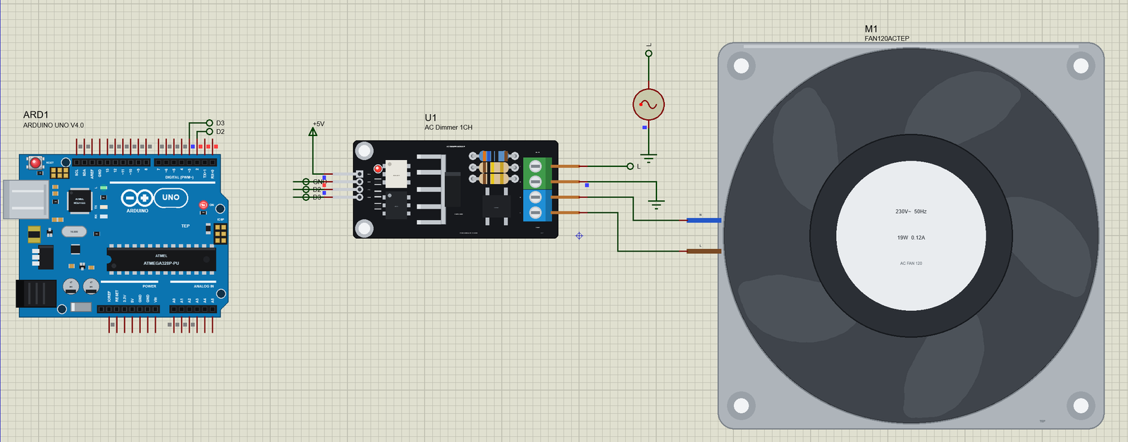
AC Dimmer Module Library for Proteus Simulation


Hello friends, I hope you all are doing great. Today, I am going to share the new AC Dimmer Module Library for Proteus Simulation, the 43rd library of our motor series and the driver for the 230 V fan of the last one. If you have searched for a Proteus simulation of an AC dimmer, of triac phase control or of zero-cross detection with an Arduino, this is the small board that does all three: the common 1-channel AC light dimmer module with a BTA16 triac, a MOC3021 gate driver and a zero-cross output, for 3.3 V and 5 V controllers.
AC Dimmer Module Library for Proteus Simulation
Latest version: V1.0 (November 2026, this tutorial)
Helping Tools
- Serial Monitor Advance: a serial terminal window for the UART of your board
- Serial Monitor Expert: the serial monitor with extra debugging tools
- LCD Library for Proteus V3.0: 16x2, 20x4 and I2C LCDs to show your readings
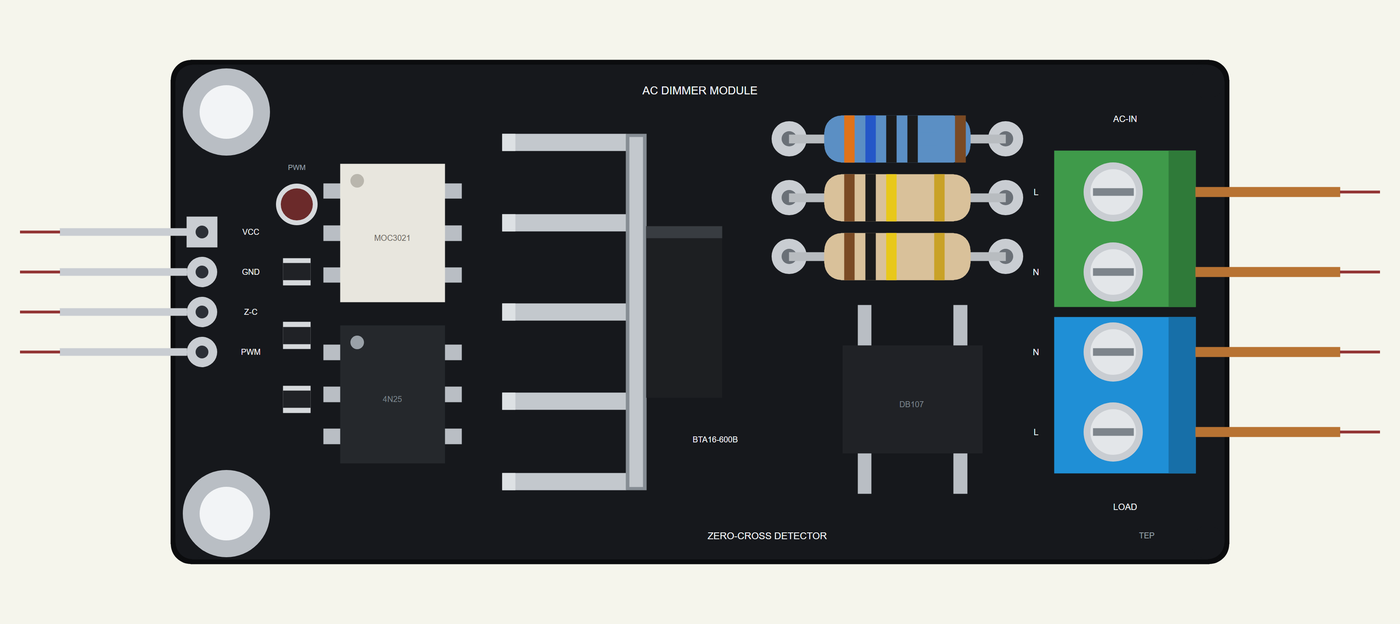
Our library brings that board into your Proteus simulation at its true size, 63 x 30 mm, with its logic header, the two optocouplers, the triac upright on its finned heatsink, the resistors, the bridge rectifier and the two screw terminals; at run time its PWM LED glows with the gate. The simulation model works like the real circuit: the zero-cross output pulses high around every zero of the mains, the triac fires when its gate path can push enough current, and then it stays on by itself until its current dies at the end of the half-cycle, even when a motor makes that current lag. In the demo an Arduino fires it at 1.5, 3, 5 and 7 ms after each zero and dims a 120 mm 230 V fan.
NOTICE: Our team has put a lot of effort into these small parts: the bodies, the animation and the pop-ups are all our own design, and you get them free. Your feedback is the fuel that keeps us going, so please tell us what you think in the comments below or in the Motor Driver board of our forum. And if our free libraries help you, you can buy us a coffee. So, let's get started with the AC Dimmer Module Library for Proteus Simulation:
What is an AC Dimmer Module?
An AC dimmer module lets a microcontroller control the power of a mains load: an incandescent or dimmable LED lamp, a heater, a soldering iron or a small motor. It does it with phase control. The mains voltage crosses zero 100 times a second on 50 Hz. After each zero the controller waits, then fires a triac; the triac then conducts until the end of that half-cycle. The longer the wait, the smaller the part of each half-cycle that reaches the load, and the lower its RMS voltage and power.
For that the controller needs two things from the board: a signal at each zero, so it knows when to start counting, and a way to fire the triac without touching the mains. This board gives both, each through an optocoupler, so the 230 V side and the 5 V side never share a wire. It is an open design built by many makers, sold as a 1-channel 3.3 V / 5 V logic dimmer for 220 V or 110 V at 50 or 60 Hz.
| The 1-channel AC dimmer module | |
|---|---|
| Board | 63 x 30 mm, two 3.2 mm holes 22 mm apart |
| Logic header | VCC (3.3 or 5 V), GND, Z-C (zero-cross output), PWM (the gate input) |
| Mains terminals | AC-IN (L, N) and LOAD (N, L); the triac switches L, N passes through |
| Triac | BTA16-600B, 16 A 600 V, on a finned heatsink; fired by a MOC3021 opto-triac |
| Zero-cross | a bridge rectifier, two droppers and a 6-pin optocoupler; Z-C pulled up to VCC |
| Rating in the model | 5 A at 230 V (our figure for this design) |
How the Zero-Cross and the Triac Work
The zero-cross detector is the bottom half of the board. A bridge rectifier and two 100 kohm resistors, in parallel to share the heat, feed the LED of an optocoupler from the mains. Whenever the mains is well away from zero, the LED is bright enough for the optocoupler's transistor to pull the Z-C pin low against its 10 kohm pull-up to VCC. Near each zero the LED goes dark, the transistor lets go, and Z-C goes HIGH. So Z-C is a short positive pulse around every zero, 100 a second on 50 Hz. The true zero is the middle of the pulse: firing from its rising edge comes about half a pulse early. (The published schematic gives no resistor values; 100 kohm, 10 kohm and the optocoupler's current ratio of 0.5 are our figures.)
The top half fires the triac. The PWM pin lights the LED of a MOC3021, a small opto-triac. Its output connects the BTA16's gate to MT2 through a resistor, 360 ohm in our model. As soon as the voltage across the BTA16 can push its gate current through that path, 50 mA at most by its datasheet, about 21 V, the BTA16 turns on. From then on it does not need the gate: a triac stays on as long as its main current flows, and turns off by itself when that current falls to zero at the end of the half-cycle. That is why one short pulse per half-cycle is enough for a lamp.
A motor is different. Its current lags its voltage, so the current of one half-cycle is still flowing when the next half-cycle has started. If the gate pulse comes and goes while that old current still flows, the triac is already on and the pulse does nothing; when the old current ends, the gate is gone and the triac misses the whole half-cycle. The cure, used in our demo, is to hold the gate high for a few milliseconds: the triac then fires again as soon as the old current ends. Our simulation model shows exactly this: with the gate held from 1.5 ms, the triac turns on at the moment the fan's lagging current ends, not at 1.5 ms.
Features of the AC Dimmer Module Library for Proteus Simulation
- The board at true scale: 63 x 30 mm, the logic header, the optocouplers, the BTA16 on its heatsink, the droppers, the gate resistor, the bridge rectifier and the screw terminals; the PWM LED glows with the gate at run time.
- A real triac: fired by the gate path when it can push 50 mA, then conducting one way (0.85 V plus 25 mohm, from the datasheet) until its current dies and the voltage across it turns round, so motor loads behave as on the bench.
- The zero-cross output: the mains through the bridge and the droppers, the optocoupler and the pull-up to VCC; every Z-C edge at its time, about a millisecond wide on 230 V.
- Measurements: the mains and its true zeros, the firing angle in milliseconds and degrees, the conduction angle, the Z-C pulse, the gate pulse, the load's voltage, current and power, and the triac's loss and junction temperature.
- A pop-up: the zero-cross and the gate on a 20 ms scope, the load on a 40 ms scope, the firing angle on a half-cycle, graphs, an event log and a check page.
- A complete package: about 1.2 MB with the library, our Arduino UNO V4.0 and the demo, without the source code of the model.
The AC Dimmer Module in Proteus
The device is DIMMERACTEP in TEPACDIMMER.LIB, under Electromechanical > Motor Drivers, with the prefix U and the mixed model TEPACDIMMER.DLL. Search DIMMER in Pick Devices. On the left are VCC, GND, Z-C (a digital output) and PWM (a digital input); on the right are L-IN and N-IN, the AC-IN terminal, and N-OUT and L-OUT, the LOAD terminal. There are no properties: the parts on the board are fixed.
Download AC Dimmer Module Library for Proteus Simulation
Click the button below to download AC-Dimmer-Module-Library-for-Proteus-v1.0.zip (about 1.2 MB, without the source code of the models):
AC Dimmer Module Library for Proteus V1.0- README.txt: installation, the demo, the wiring, troubleshooting and the limits of the simulation.
- Proteus Library Files:
TEPACDIMMER.LIBandArduinoV4TEP.LIB. - Proteus Model Files:
TEPACDIMMER.DLLandTEPARDUINO.DLL. - Arduino Code: the demo sketch.
- Proteus Simulation: the demo project, its HEX file and copies of the DLLs.
No Proteus yet? Read How to Download and Install Proteus 7 and 8. New to libraries? Follow How to Install a New Library in Proteus.
How to Install AC Dimmer Module Library for Proteus Simulation
- Close Proteus and extract the whole zip file, for example to your Desktop.
- Copy the files from Proteus Library Files into the LIBRARY folder of Proteus.
- Copy the files from Proteus Model Files into the MODELS folder.
- Delete
TEPACDIMMER.IDXfrom the LIBRARY folder if it is there. - The demo's load is our separate 120mm 230V AC Fan Library for Proteus Simulation: install its LIB and DLL too.
- Start Proteus, press P and search for DIMMER.
Proteus Simulation of the AC Dimmer with Arduino
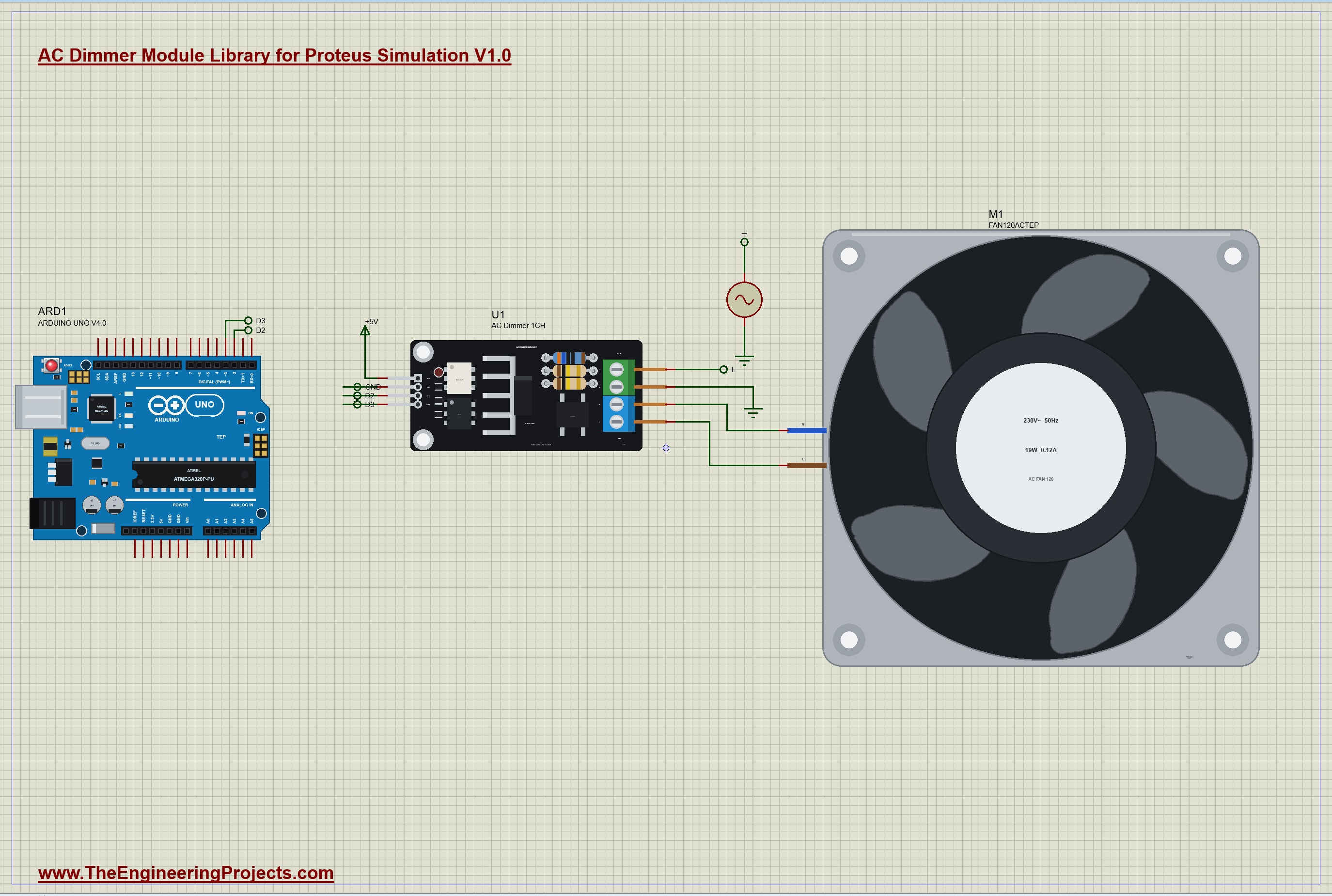
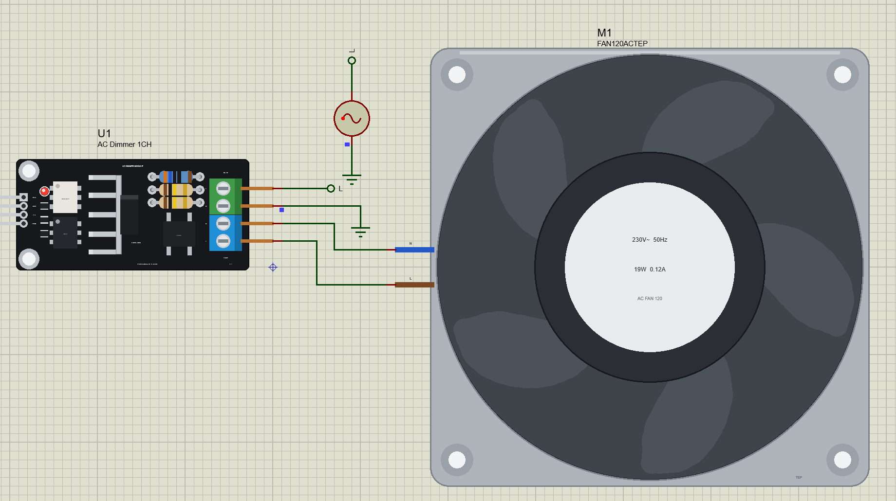
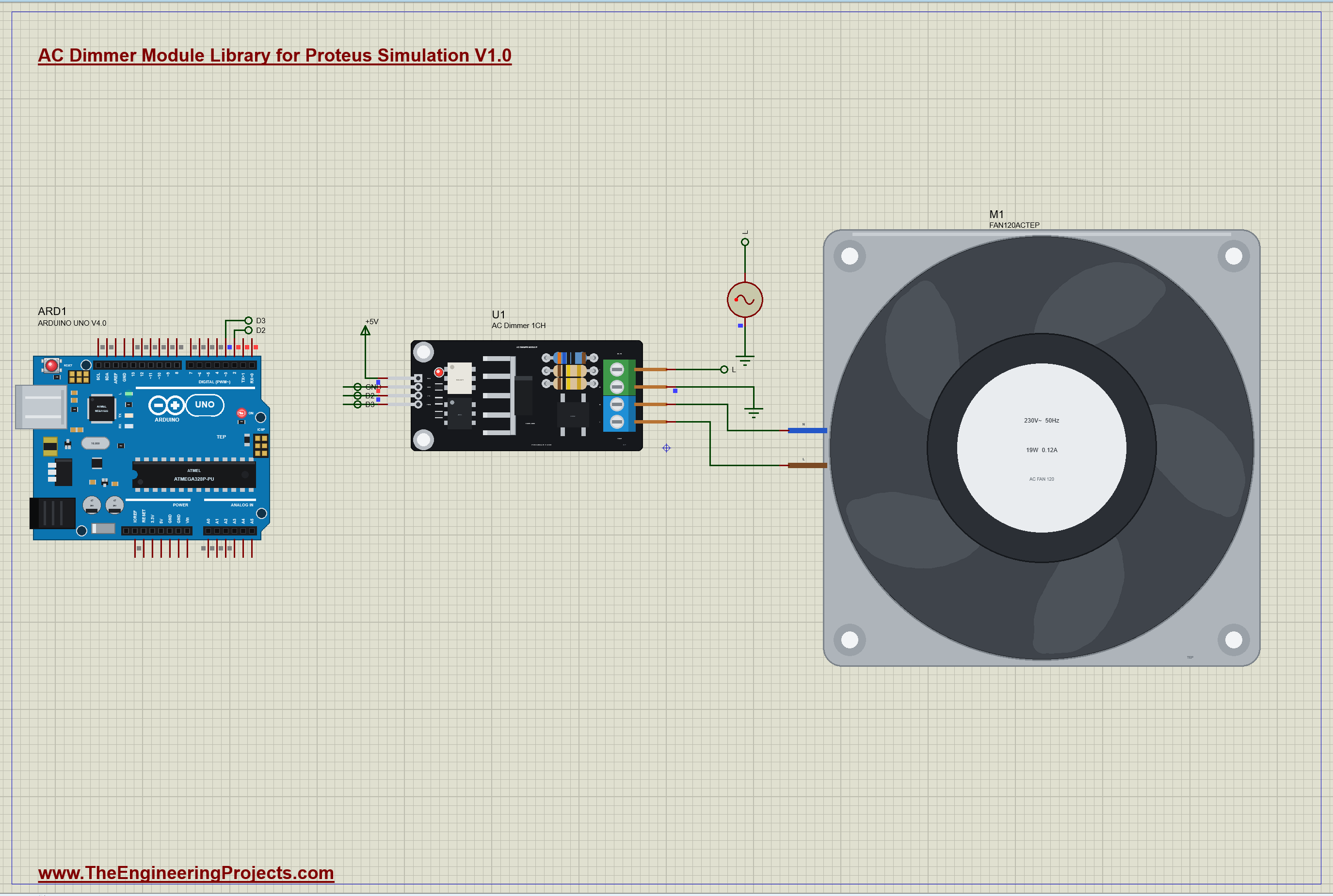
The demo has our Arduino UNO Library for Proteus V4.0 with its built-in monitor, the same window as our TEP Serial Monitor Advance for Proteus. V1 is Proteus's own ALTERNATOR at 325 V peak, 230 V RMS, 50 Hz; its minus is the ground, as the neutral of a real supply is earthed. The module's AC-IN takes it, its LOAD terminal feeds M1, the fan from our separate 120mm 230V AC Fan library (TEPACFAN120.LIB and TEPACFAN120.DLL), so install it first. Z-C goes to the UNO's D2, an interrupt pin, and PWM comes from D3; VCC is on +5V. Open ACDIMMER-FAN120AC-ArduinoUnoV4.pdsprj.
The Sketch
The sketch watches both edges of Z-C with an interrupt. On the rising edge it notes the time; on the falling edge it has the pulse's width, and the true zero is half of it after the rise:
void zeroCross() {
  const unsigned long now = micros();
  if (digitalRead(ZC_PIN) == HIGH) { riseAt = now; return; }
  const unsigned long w = now - riseAt;
  if (w > 200 && w < 3000) { zcWidth = w; zeroAt = riseAt + w / 2; zeroNew = true; ++zcCount; }
}
The loop fires the triac when the firing delay has passed since that zero, and holds the gate until 8.5 ms after it, before the next Z-C pulse:
    if (!gateOn && fireUs && (long)(now - (z + fireUs)) >= 0 && (long)(now - (z + HOLD_TO)) < 0) {
      digitalWrite(GATE_PIN, HIGH); gateOn = true; gateOffAt = z + HOLD_TO; zeroNew = false;
    }
The program is a table of firing delays in microseconds, with the time in tenths of a second:
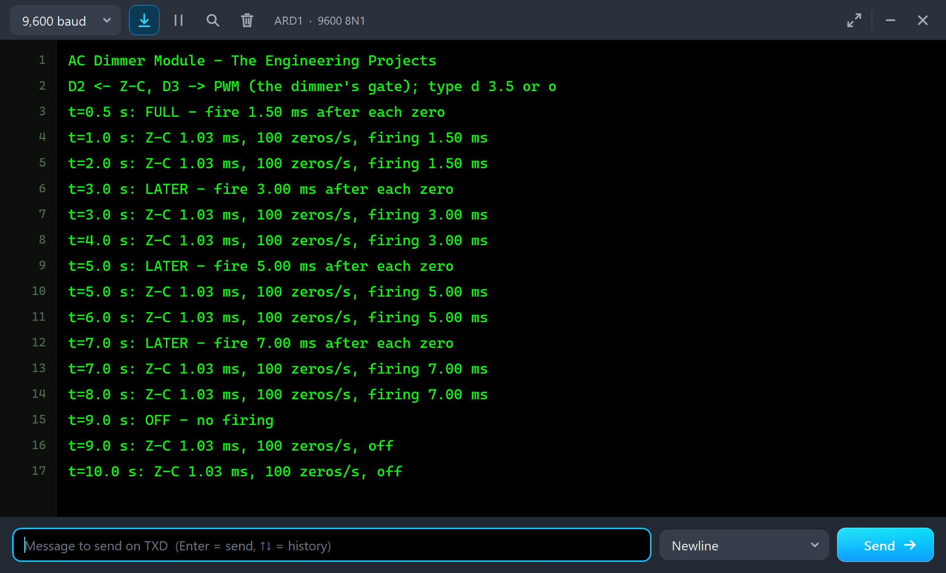
const Step PLAN[] = { {5, 1500, "FULL"}, {30, 3000, "LATER"}, {50, 5000, "LATER"}, {70, 7000, "LATER"}, {90, 0, "OFF - no firing"} };So it fires 1.5 ms after each zero from 0.5 s, at 3 ms from 3 s, at 5 ms from 5 s, at 7 ms from 7 s, and stops at 9 s. Afterwards you can type d 3.5 to fire 3.5 ms after each zero, or o for off.
AC Dimmer Simulation Results
Open the project and press Run. The program runs about 10 simulated seconds, which Proteus ran in about two and a half minutes on our PC with both pop-ups open and the pictures being taken. Click the module to open its pop-up, and the fan to open its own. Every number below comes from one simulation run, the demo exactly as it ships.
The Zero-Cross
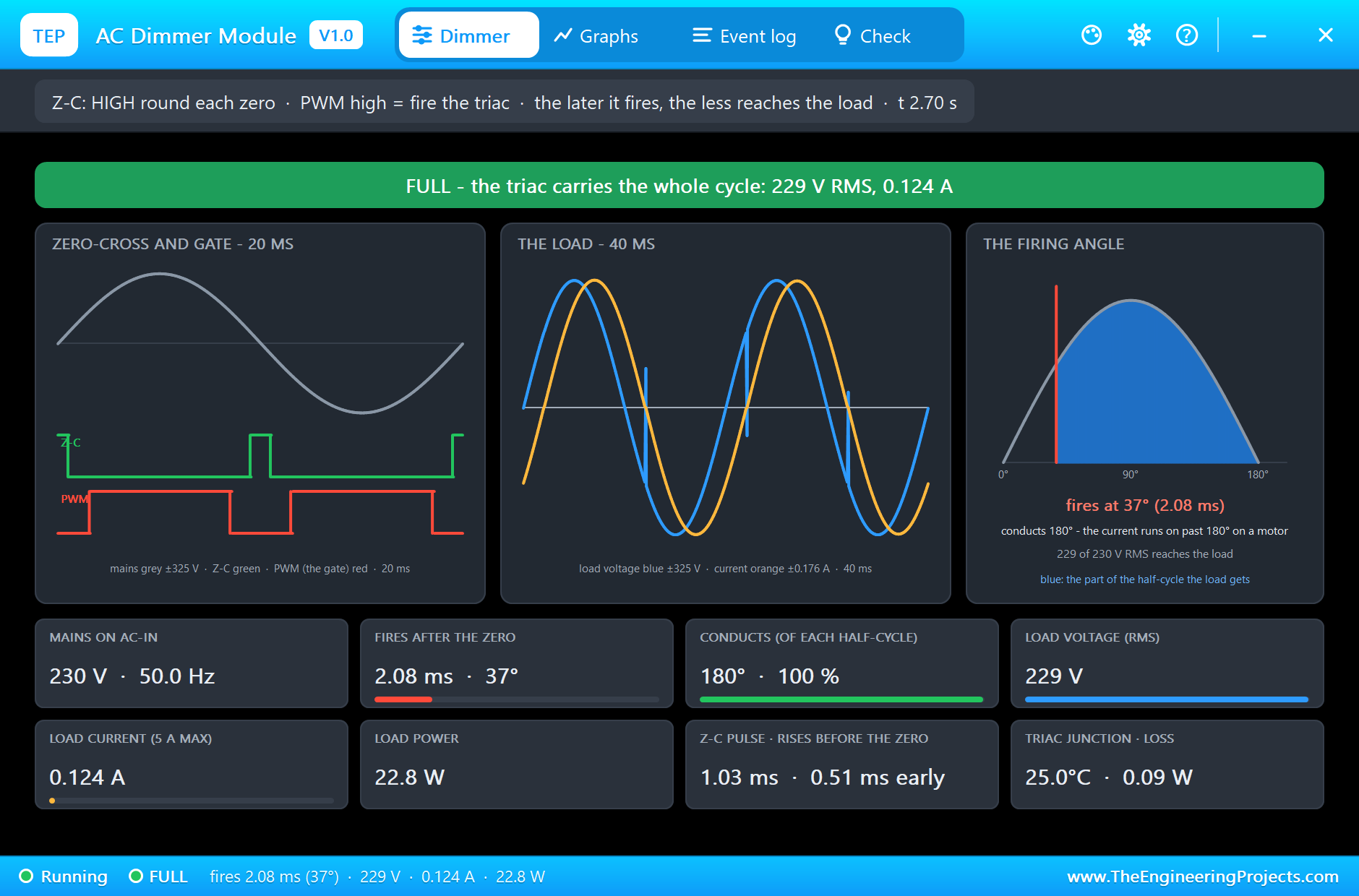
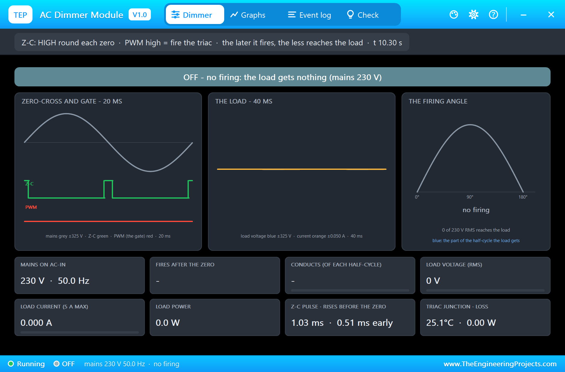
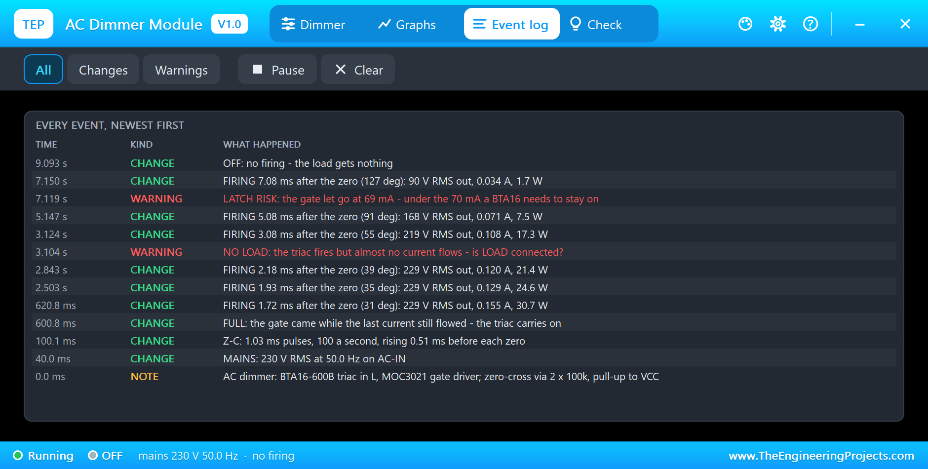
As soon as the mains is on, the Event log notes 230 V RMS at 50 Hz on AC-IN, and then the Z-C pulses: 1.03 ms wide, 100 a second, rising 0.51 ms before each zero. The left card of the pop-up shows them in green under the grey mains, with the PWM pin in red below: each gate pulse starts a set time after a zero and ends at 8.5 ms.
Fired at 1.5 ms: Full
At 0.5 s the UNO starts firing 1.5 ms after each zero. The banner reads FULL, and the firing angle card shows why: the triac turns on at 2.08 ms, 37 degrees, not at 1.5 ms. Until then the fan's current from the last half-cycle is still flowing through it; the gate is held, so the triac fires again the moment that current ends and conducts the whole 180 degrees. The fan gets 229 V RMS, 0.124 A and 22.8 W.
Fired at 3 ms
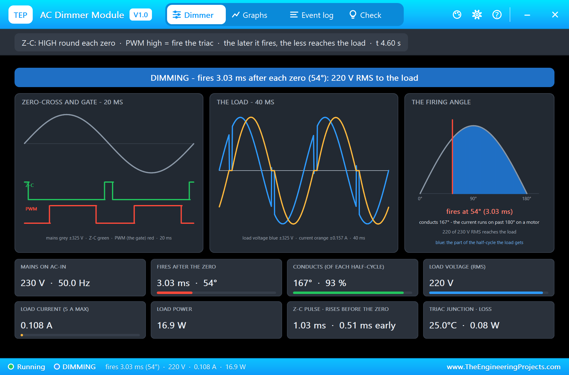
At 3 s the delay goes to 3 ms. Now the old current has ended before the gate comes, so the triac waits: it fires at 3.03 ms, 54 degrees, and conducts 167 degrees of each half-cycle, its current running on past the zero because the fan is inductive. The load gets 220 V RMS, 0.108 A and 16.9 W. The DIMMING banner and the blue part of the half-cycle on the right card show the cut.
Fired at 5 ms
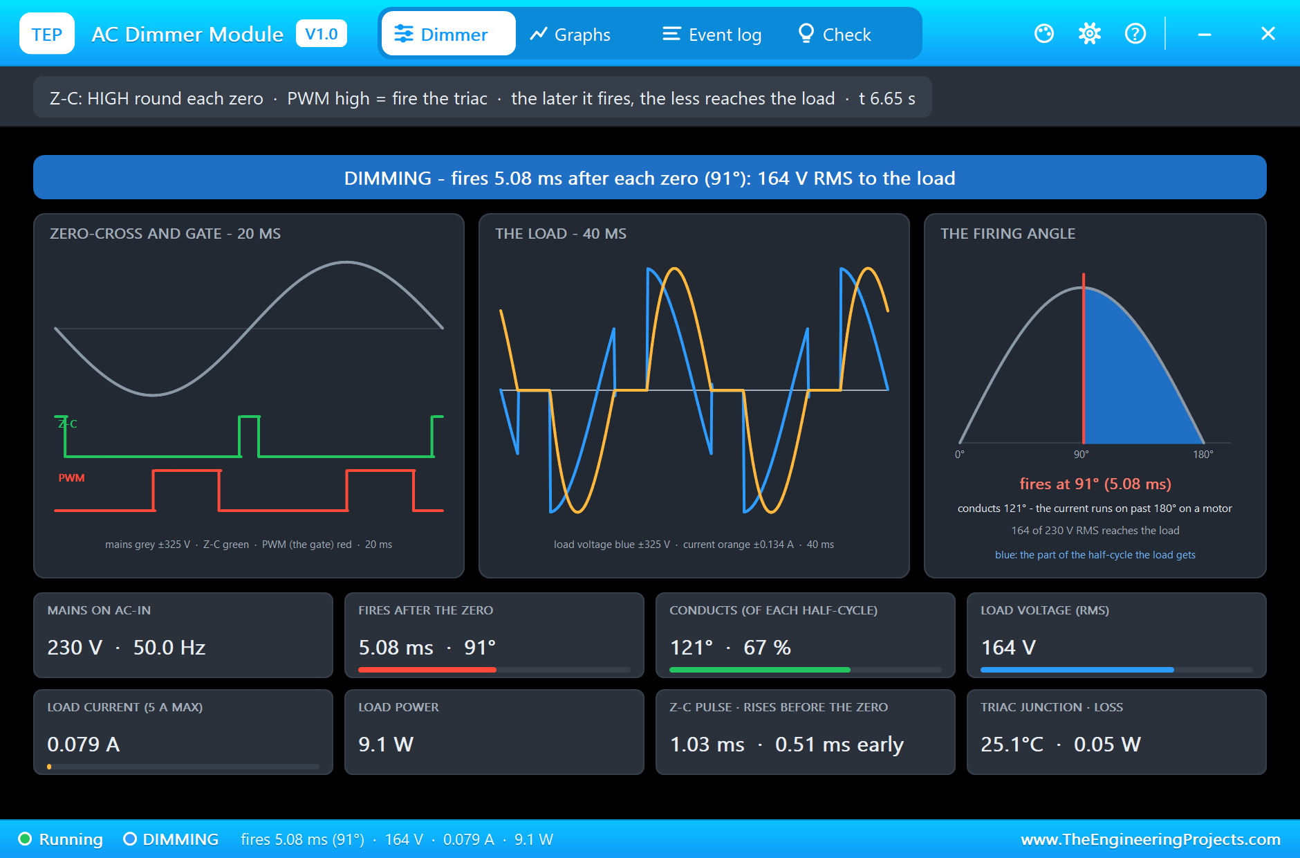
At 5 s the delay goes to 5 ms, half-way through each half-cycle: the triac fires at 5.08 ms (91 degrees) and conducts 121 degrees. The load voltage falls to 164 V RMS, the current to 0.079 A and the power to 9.1 W. The load scope shows the classic phase-control shape: nothing after each zero, then a sudden step to the mains, and a current that starts at each firing.
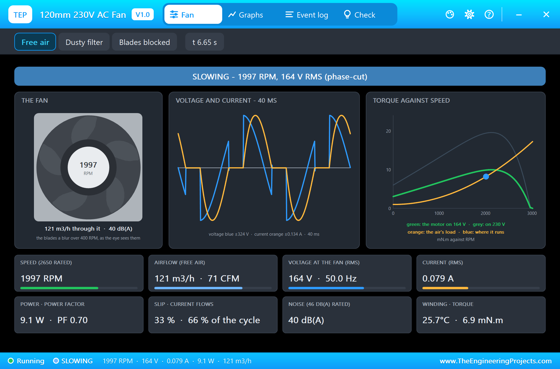
The fan's own pop-up shows the other side: the banner reads SLOWING, 1997 RPM in the picture and falling on the lower voltage, and its torque card draws the motor's curve on that voltage, now below the curve on 230 V.
Fired at 7 ms, then Off
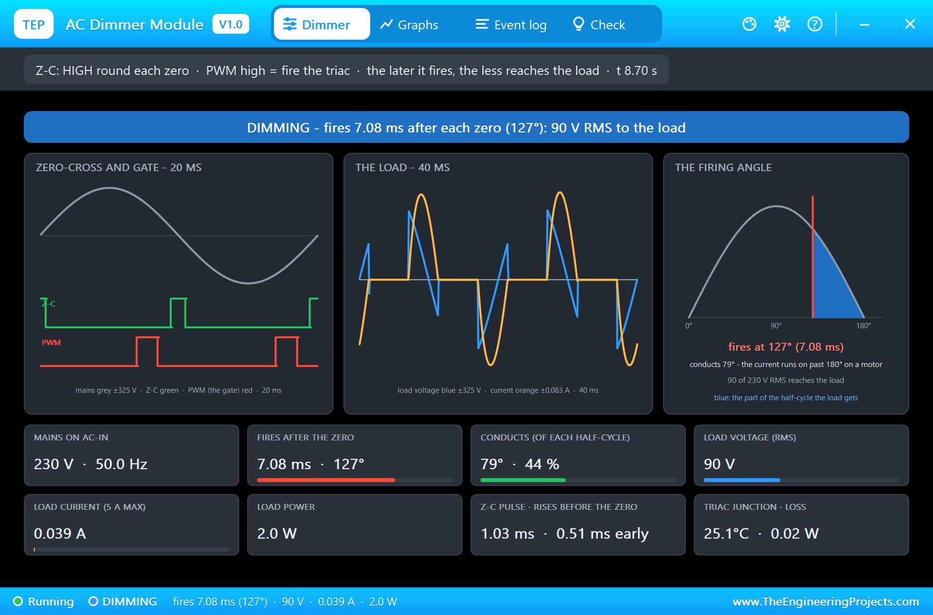
At 7 s the delay goes to 7 ms: only a small slice of each half-cycle is left. The triac fires at 7.08 ms (127 degrees) and conducts 79 degrees; the load gets 90 V RMS, 0.039 A and 2.0 W. That is too little to keep this fan turning for long: it slows on its way to a stop. At 9 s the UNO stops firing; the banner reads OFF and the load gets nothing.
The Graphs, the Event Log and the Check Page
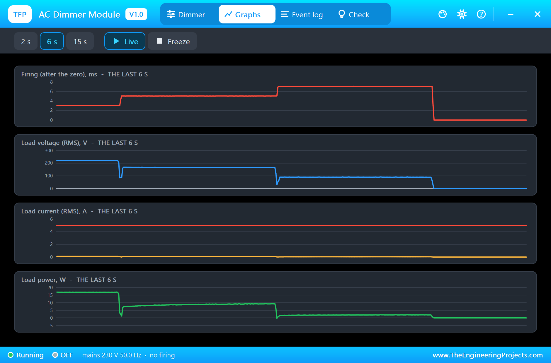
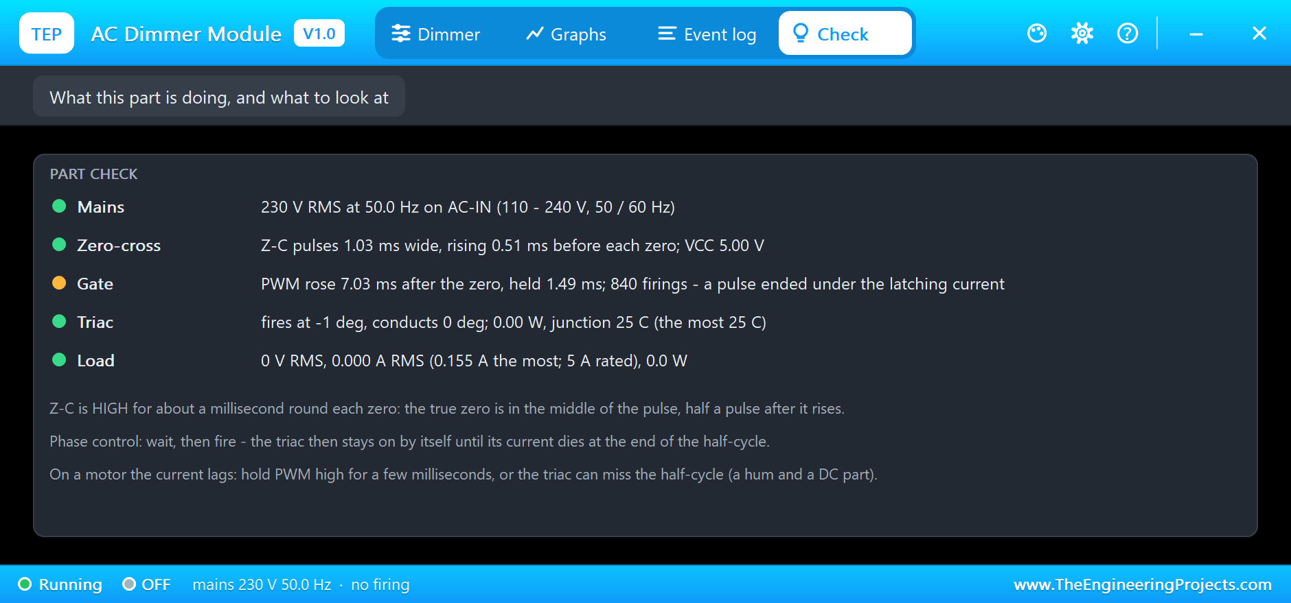
The Graphs page plots the firing delay, the load voltage, the load current and the load power over the last 2, 6 or 15 simulated seconds: four clear steps and the drop to zero. The Event log keeps the mains, the Z-C pulse, the FULL conduction and every firing with its voltage, current and power. The Check page sums up the mains, the zero-cross, the gate, the triac (its junction stayed at about 25 C with this small load) and the load against the 5 A rating.
Try It Yourself
- Type
d 2.5: the triac still fires where the old current ends, and the fan stays near full speed. - Type
d 9: a tiny slice is left; the load voltage drops to a few tens of volts. - Change the sketch to fire on the rising edge of Z-C instead of the middle: every firing comes about half a millisecond early.
- Type
d 4, thend 6: the conduction angle on the right card follows the firing, and the load voltage with it. - Replace the fan with a 1 kohm resistor: the current then follows the voltage, and the triac turns off right at each zero of the mains.
Ideas to Extend the Demo
- Map a potentiometer on A0 to the firing delay: a mains dimmer knob for a lamp.
- Add a thermistor and a PI loop: a heater that holds a set temperature.
- Use two modules on one zero-cross: two channels from one UNO.
Your Own Sketches
The demo sketch is in the zip file, and you can change it in the Arduino IDE. New to Arduino? Start with our Arduino Tutorial for Beginners. Export the compiled binary, and set the UNO's PROGRAM property to the new file. Our guide on How to get the HEX file from Arduino shows you where the file ends up.
Things to Know Before Using a Real AC Dimmer
- Mains voltage kills: AC-IN, LOAD, the triac's tab and the heatsink carry 230 V; build it in an enclosure and fuse the L line.
- Pick the right load: lamps, heaters and many motors dim well; standard LED lamps, fluorescent lamps and electronic loads do not.
- Hold the gate on motors: a few milliseconds of gate, as in this demo, keeps an inductive load from missing half-cycles.
- Find the true zero: the middle of the Z-C pulse; at 60 Hz the half-cycle is 8.3 ms, not 10.
Troubleshooting
- OFF / no firing: PWM does not reach the board, or the delay is past the half-cycle.
- NO LOAD: the triac fires but no current flows; check the LOAD wires.
- Z-C stays low: VCC is not connected (no pull-up), or there is no mains on AC-IN.
- The load flickers or hums: the firing is not tied to the zero, or the gate pulse is too short for a motor.
- The part is not simulated:
TEPACDIMMER.DLLis missing from MODELS and from the project folder.
Limitations of the Simulation
- The resistor values, the optocoupler's current ratio, the 5 A rating and the thermal figures are our figures; the published schematic gives no values.
- Any high level on PWM fires the triac; the MOC3021's own LED current and dv/dt turn-on are not modelled, and there is no snubber, as on the board.
- The triac turns off when its current has ended and the voltage across it turns round; the holding current itself is not modelled.
- Arduino is a name of Arduino; this library is not made or endorsed by Arduino, Labcenter or any dimmer maker.
- Tested in Proteus 8.5 in November 2026 (the demo as shipped). Proteus 7 is not supported.
So, that was all about the AC Dimmer Module Library for Proteus Simulation. I hope it helps you try phase control in a simulation first: a zero-cross pulse around every zero, a triac that fires from its gate path and stays on by itself, a firing angle that sets the load's voltage, and the lagging current of a motor that changes the rules, with a pop-up that shows all of it. If you have any questions, ask in the comments and I will help you out. Till the next tutorial, take care and have fun!

Comments
0