


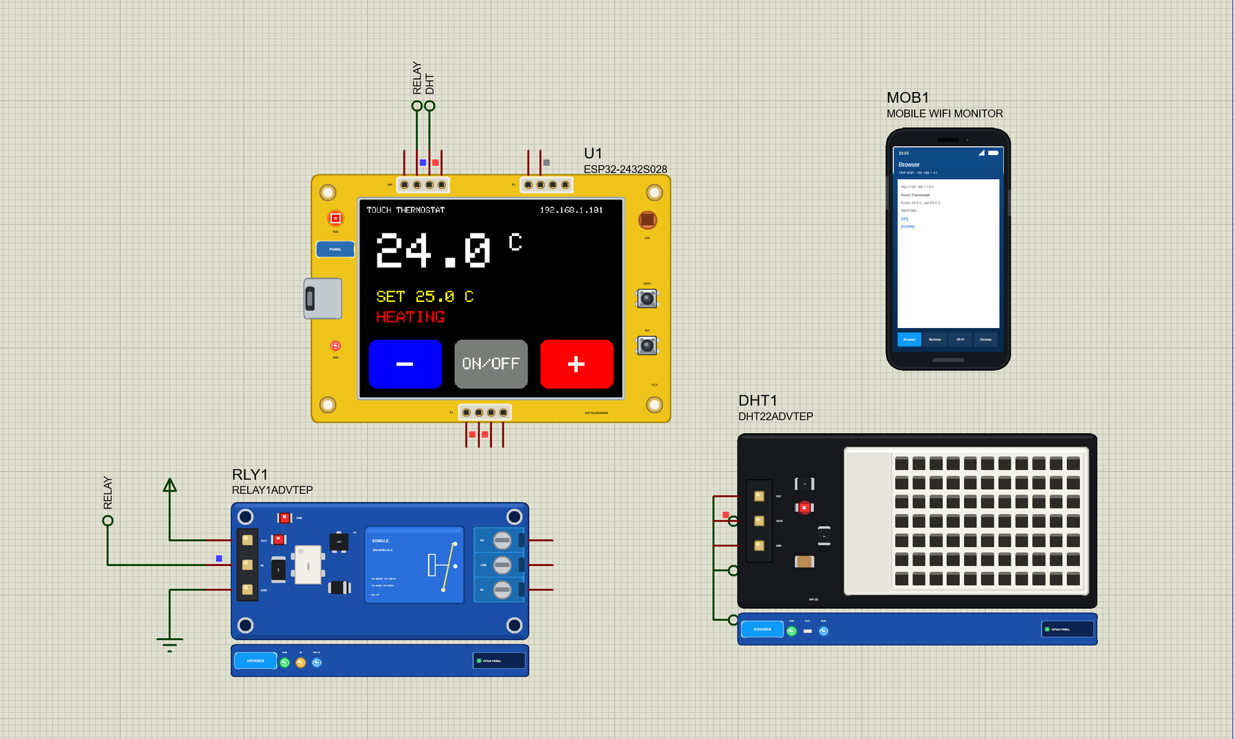
ESP32-2432S028 Cheap Yellow Display Library for Proteus: TFT Touch


Hello friends, I hope you all are doing great. Today, I am going to share the ESP32-2432S028 Cheap Yellow Display Library for Proteus. This bright yellow board has become a favourite among makers, because it puts an ESP32, a 2.8 inch colour TFT LCD and a touch screen on one small PCB at a very low price. There is nothing to wire: plug in a USB cable and you have a screen you can press. With this library it runs your ESP32 Arduino sketch in Proteus 8.5, with the display, the touch film, the RGB LED and the buttons working on the part.
ESP32-2432S028 Cheap Yellow Display Library for Proteus
Latest version: V1.0 (November 2026, this tutorial)
Helping Tools
- Laptop WiFi Monitor: a laptop on the Wi-Fi of your design: a browser, a TCP / UDP terminal and ping
- Mobile WiFi Monitor: a smartphone that opens the pages of your board and sends it commands
- Serial Monitor Advance: a serial terminal window for the UART of your board
For the demo we built a Wi-Fi touch thermostat, the kind of box you see on the wall of a modern home. A DHT22 measures the room, the screen shows the temperature in big digits, and three buttons on the glass set the temperature you want. A relay runs the heater, the RGB LED shows what the thermostat is doing, and a phone on the same Wi-Fi can change the setting from the sofa.
NOTICE: Proteus has no ESP32 model, so our team has put a lot of effort into building this board ourselves: the board's pins, buttons, RGB LED, display, touch film and Wi-Fi are all our own model, and your sketch compiles with our free TEP Boards for Proteus add-on. Your feedback is the fuel that keeps us going, so please tell us what you think in the comments below or in the ESP32-2432S028 Cheap Yellow Display board of our forum. And if our free libraries help you, you can buy us a coffee. So, let's get started with the ESP32-2432S028 Cheap Yellow Display Library for Proteus:
What is the ESP32-2432S028?
The ESP32-2432S028 is a small development board sold by many shops under nearly the same name. The name says what it is: an ESP32 with a 240 x 320 display of 2.8 inches. Makers soon nicknamed it the Cheap Yellow Display, or CYD, after its yellow PCB, and a big community has grown around it, with examples, pin maps and finished projects. The board carries an ESP32-WROOM-32 module, with two 240 MHz cores, Wi-Fi, Bluetooth and 4 MB of flash. The front is nearly all display: an ILI9341 TFT with an XPT2046 resistive touch film on top. Around it are an RGB LED, a light sensor, a TF card slot, a speaker output, BOOT and RST buttons, a micro-USB port and three tiny sockets for your own parts.
| Cheap Yellow Display | ESP32 DevKit + TFT module | |
|---|---|---|
| Display | 2.8 inch, 240 x 320 | the same, on wires |
| Touch | resistive, built in | only on some modules |
| Wiring needed | none | about 14 wires |
| Free pins | a few, on three small sockets | plenty |
| Best for | panels and dashboards | learning and prototypes |
Why Is It So Popular?
A bare ESP32 and a bare display are both cheap, but joining them takes a breadboard, more than a dozen wires and an evening of checking pins. The CYD skips all of that. It also shows what a small screen can do for a project. A thermostat, a weather panel, a printer monitor or a door bell stops being a box of wires and starts to look like a real product. The price of that comfort is the pins. The display and the touch film use most of the ESP32, so only a few GPIOs are left for you. Our demo uses two of them, and that is enough for a sensor and a relay. If you would rather learn the display on its own, our TFT ILI9341 Library for Proteus has the same controller as a separate module.
Features of the ESP32-2432S028 Library for Proteus
- The board as it looks: the yellow PCB, the large display in its metal edge, the micro-USB port, the small sockets, the RGB LED, the LDR and the buttons, with our small TEP signature.
- Your sketch: a .hex for "ESP32-2432S028 Cheap Yellow Display (TEP Proteus)" with the real GPIO numbers - analogRead 0 to 4095, analogWrite and ledc PWM, attachInterrupt, tone, Serial, Wire and SPI.
- The display on the part: the ILI9341 with Adafruit's library, 320 x 240 pixels in full colour.
- A touch screen you can click: press the glass with the mouse, and your sketch reads the place from the XPT2046.
- The RGB LED and buttons: three colours on GPIO4, 16 and 17, with BOOT and RST.
- Wi-Fi: WebServer and HTTPClient in station mode, with our phone and laptop windows on the same network.
- A complete package: about 3.9 MB with the part, the add-on, the DHT22, relay and Wi-Fi monitor libraries and the demo, without the source code of the models.
The ESP32-2432S028 in Proteus
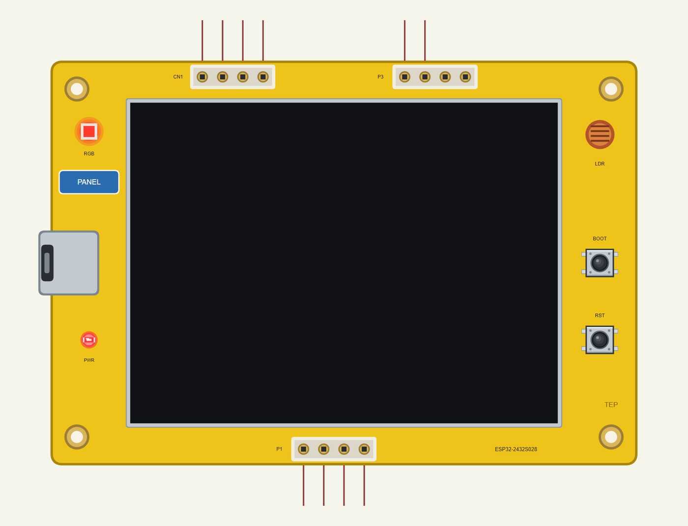
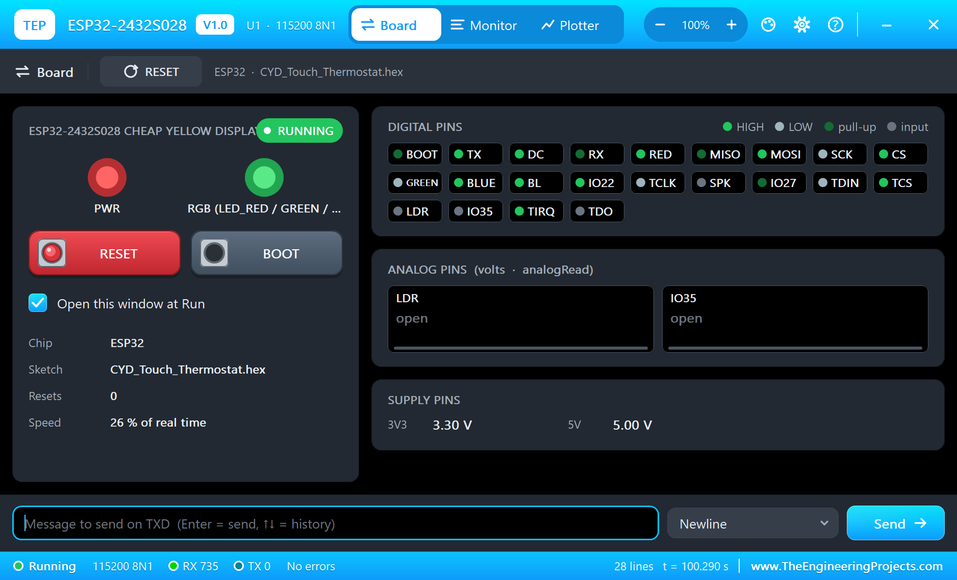
Search 2432 in Pick Devices; the device is in TEPCYD2432.LIB (Microprocessor ICs, ESP32 Boards), with the prefix U. The board has two windows: click the micro-USB port for the serial monitor, and the blue PANEL pad for the panel. A click on the glass does not open anything, because the glass is the touch screen. On the real board the RGB LED and the two buttons sit on the back; we drew them beside the display, so that you can see them while the sketch runs.
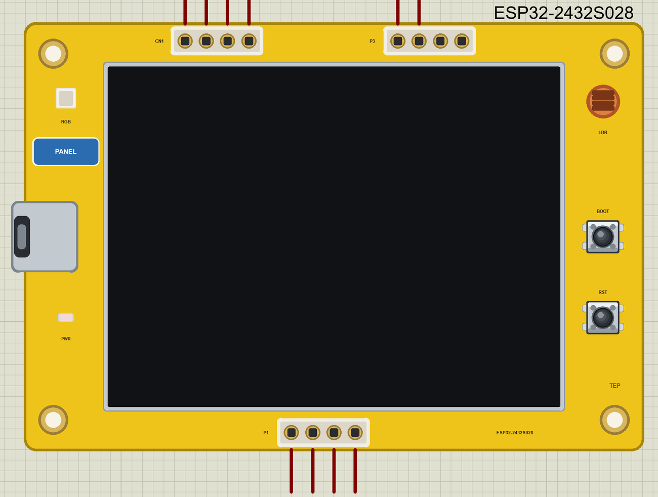
The Pins
| Socket | Pins | What the library does with them |
|---|---|---|
| CN1 | IO22, IO27 | GPIO, PWM, interrupt, or Wire |
| CN1 | 3V3, GND | the supply |
| P3 | IO35 | input only, analogRead |
| P1 | VIN, TX, RX, GND | 5 V, Serial and ground |
| Inside | 13, 12, 14, 15, 2, 21 | the display and its backlight |
| Inside | 25, 32, 33, 36, 39 | the touch controller |
| Inside | 4, 16, 17 | the RGB LED, lit when LOW |
The variant gives the inside pins names, such as TFT_CS, XPT2046_IRQ and CYD_LED_RED, so a sketch reads clearly. On P3 the pins IO22 and IO21 are drawn only: IO22 is the same pin as on CN1, and IO21 is the backlight of the display. The TF card, the speaker's sound and the light on the LDR are not modelled.
Download ESP32-2432S028 Library for Proteus
Click the button below to download ESP32-2432S028-Library-for-Proteus-v1.0.zip (about 3.9 MB, without the source code of the models):
ESP32-2432S028 Cheap Yellow Display Library for Proteus V1.0- README.txt: installation, the demo, the pins, the touch film, the properties, troubleshooting and the limits.
- Proteus Library Files:
TEPCYD2432.LIBand the demo's parts:TEPDHT.LIB,TEPRELAY.LIB,TEPMOBILE.LIBandTEPLAPTOP.LIB. - Proteus Model Files:
TEPNET.DLL,TEPDHT.DLLandTEPRELAY.DLL. - Arduino Code: the demo sketch and the TEP Boards for Proteus add-on 1.50.0.
- Proteus Simulation: the demo project, its HEX file and copies of the DLLs.
No Proteus yet? Read How to Download and Install Proteus 7 and 8. New to libraries? Follow How to Install a New Library in Proteus.
How to Install ESP32-2432S028 Library for Proteus
- Close Proteus and extract the whole zip file, for example to your Desktop.
- Copy the files from Proteus Library Files into the LIBRARY folder of Proteus.
- Copy the DLLs from Proteus Model Files into the MODELS folder, replacing an older TEPNET.DLL.
- Delete
TEPCYD2432.IDXfrom the LIBRARY folder if it is there. - For your own sketches, copy Arduino Code\TEP Boards for Proteus\hardware into your Arduino sketchbook (Documents\Arduino) and restart the Arduino IDE; the board is ESP32-2432S028 Cheap Yellow Display (TEP Proteus). Install Adafruit ILI9341, Adafruit GFX, Adafruit BusIO, the DHT sensor library and Adafruit Unified Sensor from the Library Manager.
- Start Proteus, press P and search for 2432.
Demo: a Wi-Fi Touch Thermostat
A heater with a plain on and off switch wastes money. It runs until somebody feels too warm, and then it stays off until somebody feels too cold. A thermostat does that job all day without help. A touch screen makes it pleasant to use, because the buttons can change with the job, and Wi-Fi means you can turn the heat down from the next room. All of that fits on this one board.
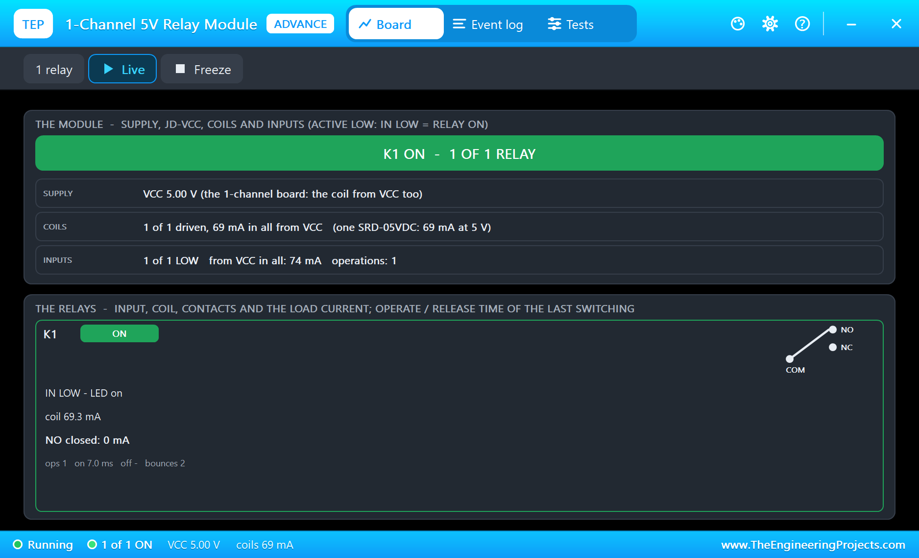
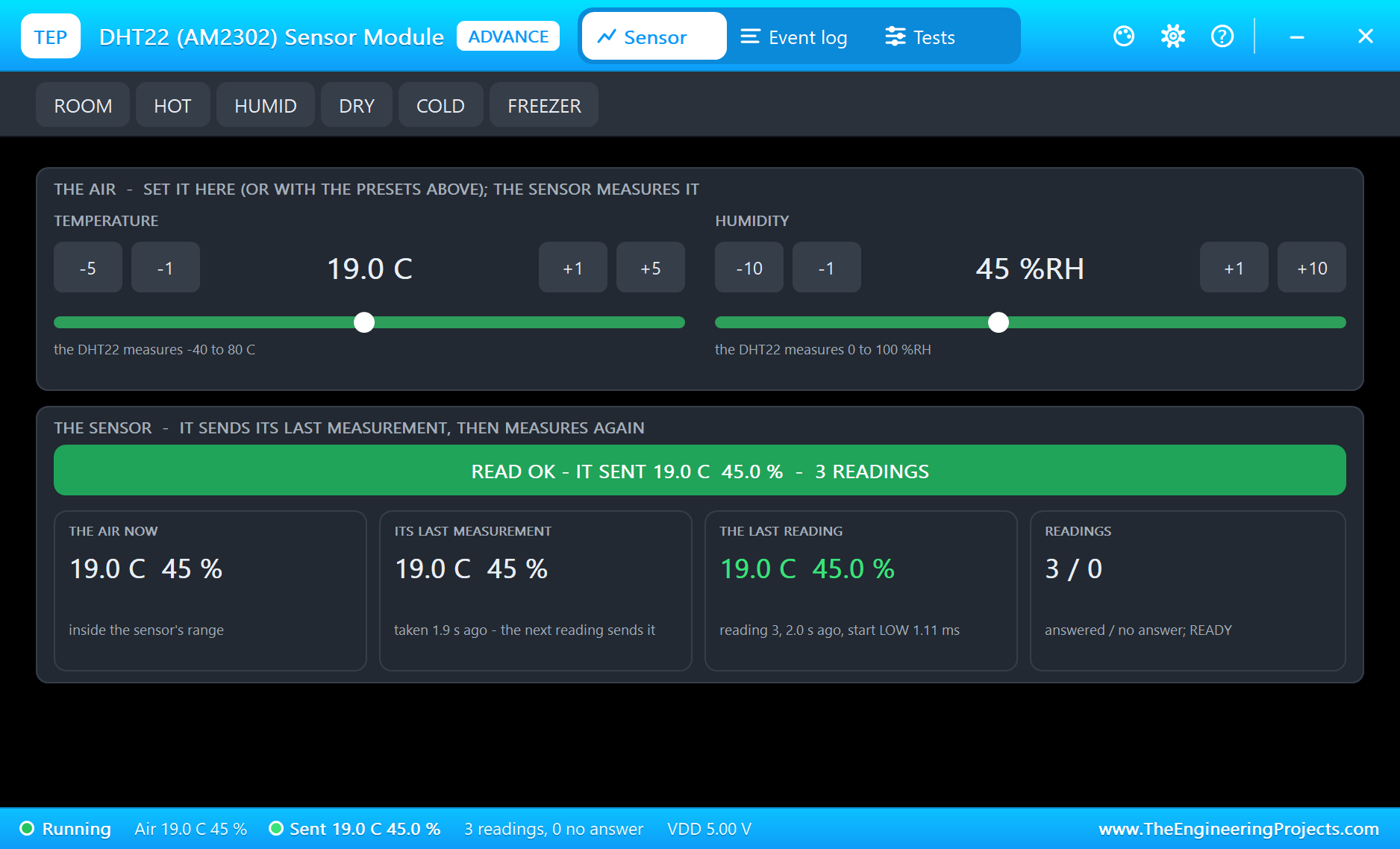
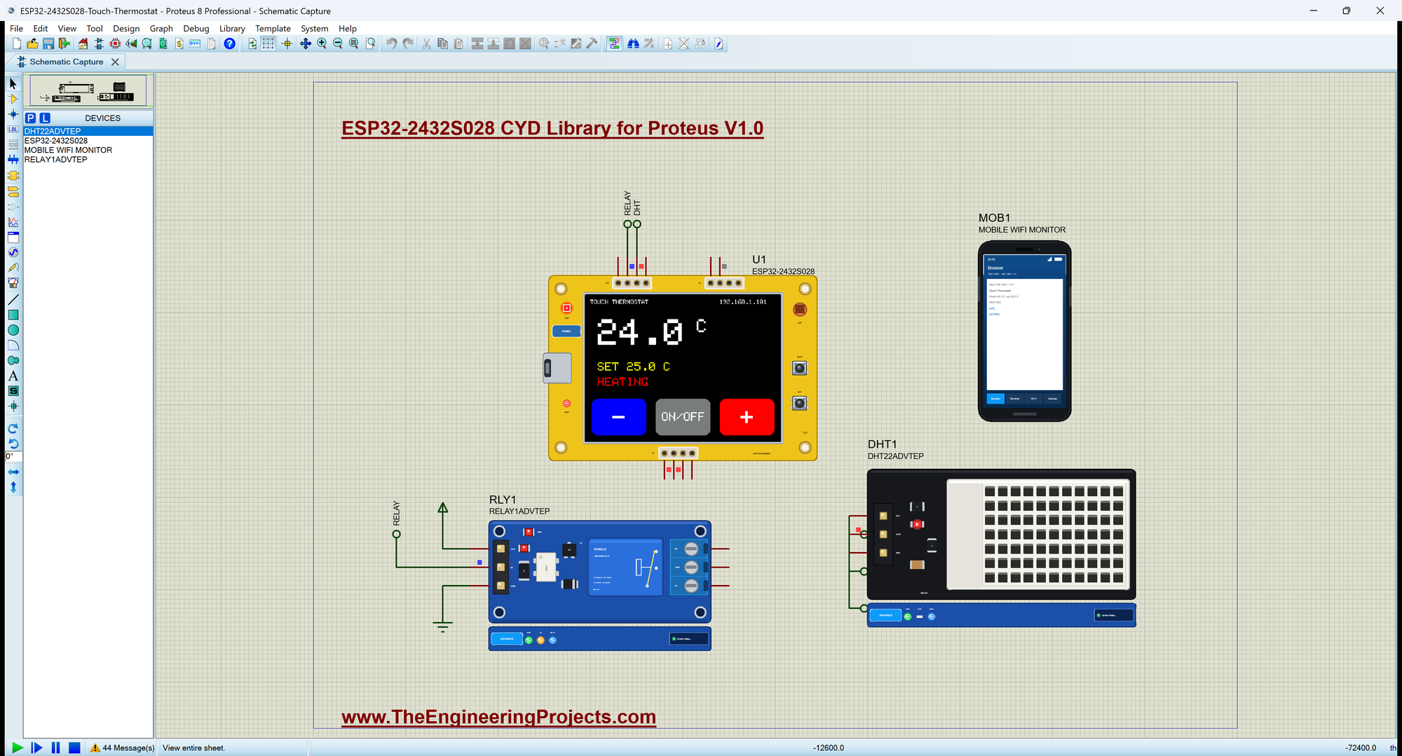
Open ESP32-2432S028-Touch-Thermostat.pdsprj. U1 runs CYD_Touch_Thermostat.hex. DHT1 is the sensor from our DHT11 and DHT22 Library for Proteus and RLY1 is the heater's relay from our Relay Module Library for Proteus, both in the Advance version. MOB1 is our Mobile WiFi Monitor, and the monitor is the same window as our TEP Serial Monitor Advance for Proteus.
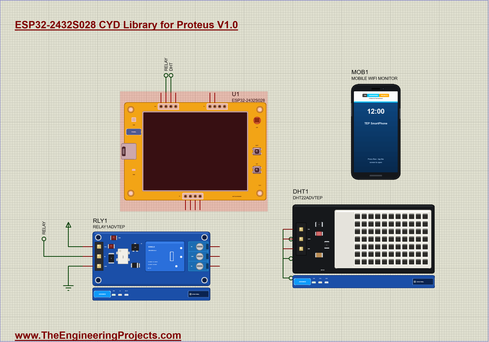
| Module pin | Net label | Board pin | What it does |
|---|---|---|---|
| DHT22 DATA | DHT | IO27 | the temperature, on one wire |
| Relay IN | RELAY | IO22 | LOW closes the relay |
| VCC, GND | VCC, GND | - | the supply |
How a Resistive Touch Screen Works
A resistive touch screen is two thin, clear films, one above the other, each with a coating that conducts electricity, but not very well. Tiny spacers keep them apart. When you press, the top film bends and touches the bottom one at that spot. To find X, the controller puts a voltage across one film from side to side, so the film acts like a long potentiometer, and it reads the voltage on the other film. The reading says how far across the press is. Then it swaps the films to find Y.
The XPT2046 does this with a 12-bit ADC, so each reading is a number from 0 to 4095, and its IRQ pin goes LOW while something presses the film. Because the screen feels pressure, not the charge of your skin, it works with a fingernail, a glove or a plastic pen, which a phone's capacitive screen will not.
Talking to the XPT2046
On the CYD the touch controller does not share the display's SPI bus. It has five pins of its own: CLK, DIN, CS, DOUT and IRQ. Our demo clocks it by hand, which takes only a few lines, works the same on a real board and shows exactly what happens on the wires. The first function sends a byte, one bit at a time. Each pulse on CLK moves one bit into the chip:
void clockOut(byte value) {
  for (byte i = 0; i < 8; i++) {
    digitalWrite(XPT2046_MOSI, (value & 0x80) ? HIGH : LOW);
    value <<= 1;
    digitalWrite(XPT2046_CLK, HIGH);
    digitalWrite(XPT2046_CLK, LOW);
  }
}
To read a channel, the sketch pulls CS LOW, sends the command byte and then clocks in 12 bits, with the most significant bit first. Each bit is added at the bottom of the number, so after twelve pulses the whole reading is there:
int readChannel(byte command) {                             // the control byte, then 12 bits, MSB first
  digitalWrite(XPT2046_CS, LOW);
  clockOut(command);
  int value = 0;
  for (byte i = 0; i < 12; i++) {
    digitalWrite(XPT2046_CLK, HIGH);
    digitalWrite(XPT2046_CLK, LOW);
    value = (value << 1) | digitalRead(XPT2046_MISO);
  }
  digitalWrite(XPT2046_CS, HIGH);
  return value;
}
From Raw Numbers to Pixels
The command byte picks the channel: 0x90 reads X and 0xD0 reads Y. The answers are raw ADC numbers, and the film never quite reaches 0 or 4095, because the edge of the glass sits inside the film. map() turns them into pixels of the 320 x 240 screen. On a real board, press the four corners and print the raw numbers to find your own limits, because every film is a little different. The IRQ test comes first, so the sketch spends no time on the film while nobody touches it:
bool readTouch(int &x, int &y) {                            // pixels of the 320 x 240 screen
  if (digitalRead(XPT2046_IRQ) != LOW) return false;
  const int rawX = readChannel(0x90), rawY = readChannel(0xD0);
  x = map(rawX, 240, 3855, 0, 319);
  y = map(rawY, 290, 3805, 0, 239);
  return true;
}
Buttons on a Screen
A button on a touch screen is only a rectangle that the sketch remembers. A small struct holds its place, size, text and colour; one function draws it, and inside() asks whether a touch landed on it. The important detail is in handleTouch(). It acts only when the film goes from not touched to touched. Without that test, one press would change the setting again on every trip through loop(), and the number would run away:
void handleTouch() {
  int x, y;
  const bool touched = readTouch(x, y);
  if (touched && !wasTouched) {
    Serial.print(F("Touch at ")); Serial.print(x); Serial.print(F(", ")); Serial.println(y);
    if (inside(MINUS, x, y)) changeTarget(-1.0);
    else if (inside(PLUS, x, y)) changeTarget(1.0);
    else if (inside(POWER, x, y)) {
      enabled = !enabled;
      Serial.println(enabled ? F(">> Thermostat ON") : F(">> Thermostat OFF"));
      control();
      drawNumbers();
    }
  }
  wasTouched = touched;
}
Why a Thermostat Needs Hysteresis
Suppose the heater stops at exactly 22.0 C. The room drifts down to 21.9 C, the heater starts, warms the air back to 22.0 C and stops, over and over. The relay would click all day and soon wear out. A real thermostat uses two limits, and the gap between them is called hysteresis. Ours starts the heater below the set temperature and stops it 0.5 C above. Look at the line that decides: while the heater runs it compares with the upper limit, and while it rests it compares with the lower one:
void control() {
  const bool wanted = enabled && (heating ? room < target + BAND : room < target);
  if (wanted != heating) {
    heating = wanted;
    Serial.println(heating ? F(">> Heater ON") : F(">> Heater OFF"));
  }
  digitalWrite(RELAY_PIN, heating ? LOW : HIGH);            // the relay module: LOW = on
  setRgb();
}
Starting the Display
The display has its own SPI bus on pins 12, 13 and 14, so SPI.begin() gets the pin numbers. tft.begin() sends the ILI9341 its long list of settings, and setRotation(1) turns the picture into landscape, with the micro-USB on the left. The backlight is a plain pin on IO21, so a real sketch can dim it with PWM. The relay pin is set HIGH before anything else, so the heater cannot blink on during the start. Note the single call to readChannel() near the end: the first conversion turns on the pen interrupt.
void setup() {
  Serial.begin(115200);
  Serial.println(F("CYD Touch Thermostat - The Engineering Projects"));
  pinMode(RELAY_PIN, OUTPUT); digitalWrite(RELAY_PIN, HIGH);
  pinMode(CYD_LED_RED, OUTPUT); pinMode(CYD_LED_GREEN, OUTPUT); pinMode(CYD_LED_BLUE, OUTPUT);
  digitalWrite(CYD_LED_RED, HIGH); digitalWrite(CYD_LED_GREEN, HIGH); digitalWrite(CYD_LED_BLUE, HIGH);
  pinMode(XPT2046_CS, OUTPUT); digitalWrite(XPT2046_CS, HIGH);
  pinMode(XPT2046_CLK, OUTPUT); digitalWrite(XPT2046_CLK, LOW);
  pinMode(XPT2046_MOSI, OUTPUT);
  pinMode(XPT2046_MISO, INPUT);
  pinMode(XPT2046_IRQ, INPUT);
  pinMode(TFT_BL, OUTPUT); digitalWrite(TFT_BL, HIGH);
  SPI.begin(TFT_SCLK, TFT_MISO, TFT_MOSI, TFT_CS);
  tft.begin();
  tft.setRotation(1);
  tft.fillScreen(ILI9341_BLACK);
  tft.setTextColor(ILI9341_WHITE); tft.setTextSize(2); tft.setCursor(40, 110); tft.print(F("Touch Thermostat"));
  readChannel(0x90);                                        // the first conversion turns the pen interrupt on
  dht.begin();
  WiFi.begin(WIFI_NAME, WIFI_PASS);
  while (WiFi.status() != WL_CONNECTED) delay(100);
  Serial.print(F("Wi-Fi: http://")); Serial.print(WiFi.localIP()); Serial.println(F("/"));
  server.on("/", handleRoot);
  server.on("/up", []() { changeTarget(1.0); handleRoot(); });
  server.on("/down", []() { changeTarget(-1.0); handleRoot(); });
  server.begin();
  room = dht.readTemperature();
  drawAll();
  control();
}
Drawing Only What Changes
This screen has 76,800 pixels, and each one takes two bytes on the SPI bus. Clearing all of them takes long enough to see, so a sketch that redraws everything on every reading flickers. Ours draws the title and the buttons once, in drawAll(). After that, only the strip with the numbers is cleared and written, and only when a number has changed. The same rule keeps the sketch quick, because the touch film gets read in between:
void drawNumbers() {
  tft.fillRect(0, 30, 320, 130, ILI9341_BLACK);
  tft.setTextColor(ILI9341_WHITE); tft.setTextSize(6); tft.setCursor(20, 40); tft.print(room, 1); tft.setTextSize(3); tft.print(F(" C"));
  tft.setTextColor(ILI9341_YELLOW); tft.setTextSize(2); tft.setCursor(20, 110); tft.print(F("SET ")); tft.print(target, 1); tft.print(F(" C"));
  tft.setCursor(20, 135);
  if (!enabled) { tft.setTextColor(ILI9341_CYAN); tft.print(F("OFF")); }
  else if (heating) { tft.setTextColor(ILI9341_RED); tft.print(F("HEATING")); }
  else { tft.setTextColor(ILI9341_GREEN); tft.print(F("AT TEMPERATURE")); }
}
The RGB LED
Each colour of this LED sits between 3.3 V and its GPIO, so the pin has to go LOW to light it. That catches many people the first time, because the LED is on when the board starts and the pins are still floating or LOW. Our sketch sets all three HIGH in setup(), then uses this small function, which turns one colour on for each state:
void setRgb() {                                             // the board's RGB LED is lit when LOW
  digitalWrite(CYD_LED_RED, enabled && heating ? LOW : HIGH);
  digitalWrite(CYD_LED_GREEN, enabled && !heating ? LOW : HIGH);
  digitalWrite(CYD_LED_BLUE, enabled ? HIGH : LOW);
}
The Page for the Phone
WebServer calls a function for each address, and that function builds the page as a String. The two links, /up and /down, call the same changeTarget() as the buttons on the glass, so the screen and the phone can never disagree. Any browser on the same Wi-Fi can use the page, and no app is needed:
void handleRoot() {
  String h = F("<html><body><h2>Touch Thermostat</h2><p>Room ");
  h += String(room, 1) + F(" C, set ") + String(target, 1) + F(" C</p><p>");
  h += heating ? F("HEATING") : F("IDLE");
  h += F("</p><p><a href='/up'>UP</a></p><p><a href='/down'>DOWN</a></p></body></html>");
  server.send(200, "text/html", h);
}
Keeping the Loop Quick
Four small jobs share loop(): the web server, the touch film, the sensor and the log. Each one checks its own clock with millis() or a pin, and returns at once when it has nothing to do. handleTouch() must run often, or a short press is missed, so the sketch never waits inside a function. A DHT22 only gives a new reading about every two seconds, so the sketch asks every 2.5 seconds and leaves it alone in between.
Run the Demo
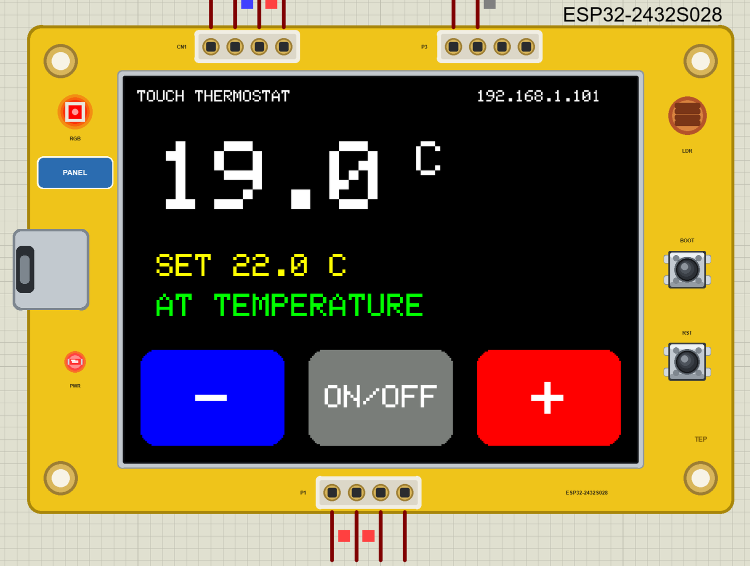
Press Run. The board joins the Wi-Fi network, reads the sensor and draws the screen. The room is at 19 C and the set temperature is 22 C, so the heater starts straight away. The monitor prints a status line every ten seconds:
CYD Touch Thermostat - The Engineering Projects
Wi-Fi: http://192.168.1.101/
>> Heater ON
Room 19.0 C  set 22.0 C  heating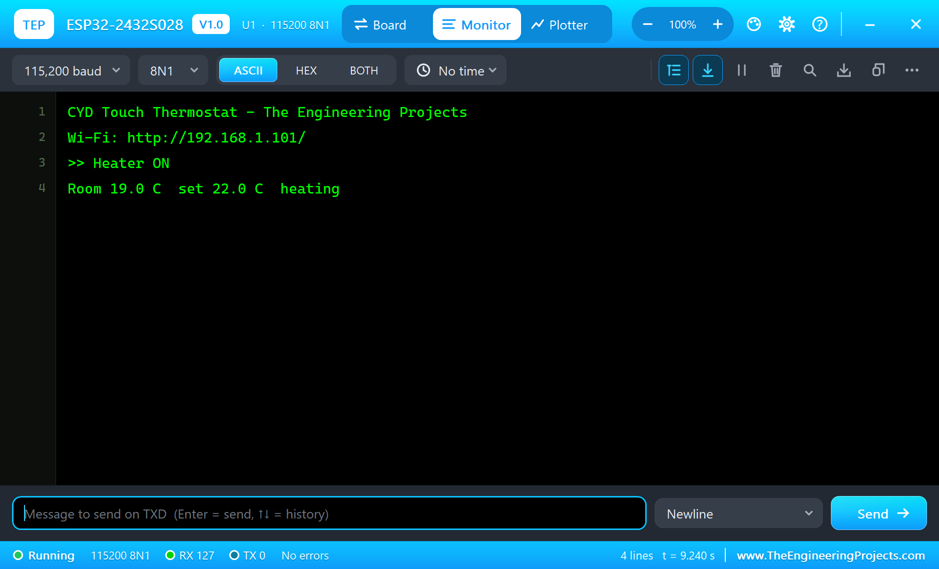
The Room Warms Up
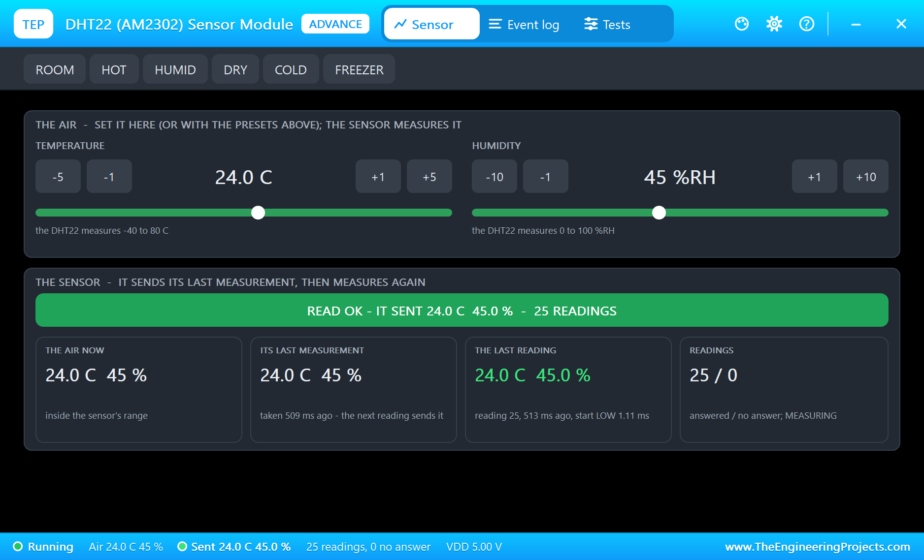
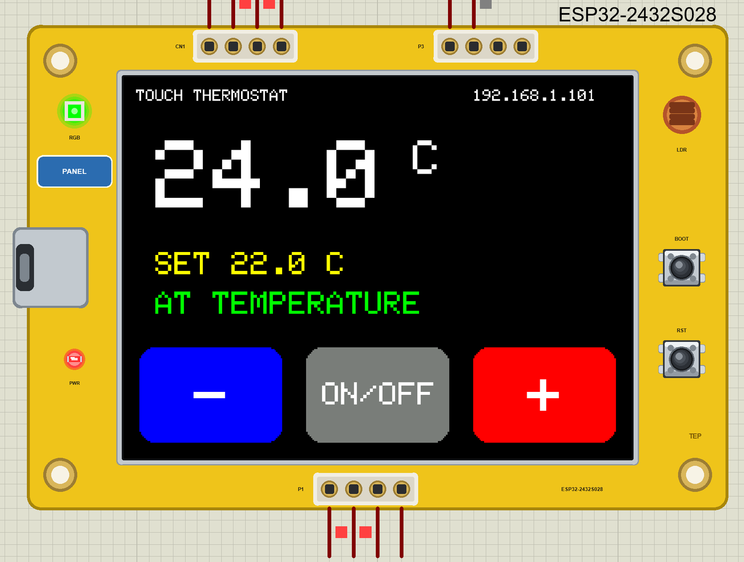
Click +5 on the DHT22's window. The next reading is 24 C, which is above the upper limit of 22.5 C. The heater stops, the relay opens, the screen says AT TEMPERATURE and the LED turns green:
Touch the Screen
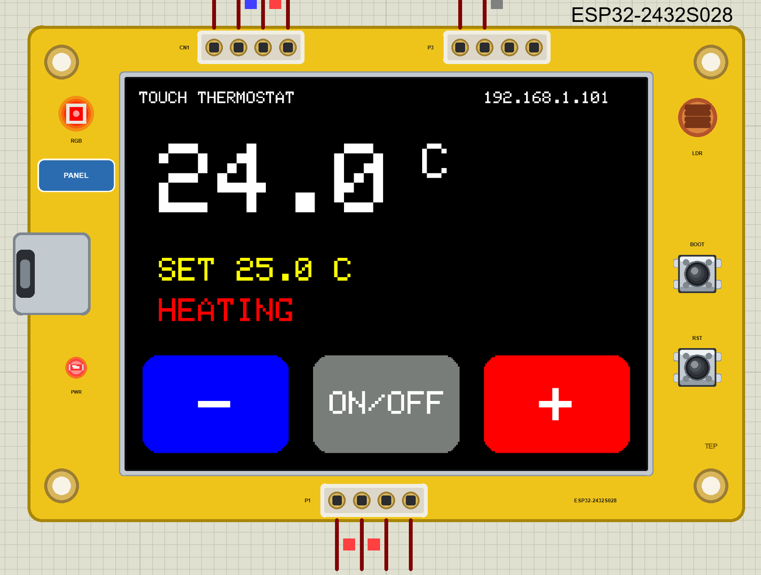
Now click the red + button on the glass with the mouse. Each click adds one degree. At 25 C the room is too cold again, so the heater starts and the LED turns red. The serial monitor prints the place of every touch, which is handy for checking your own buttons:
The Phone
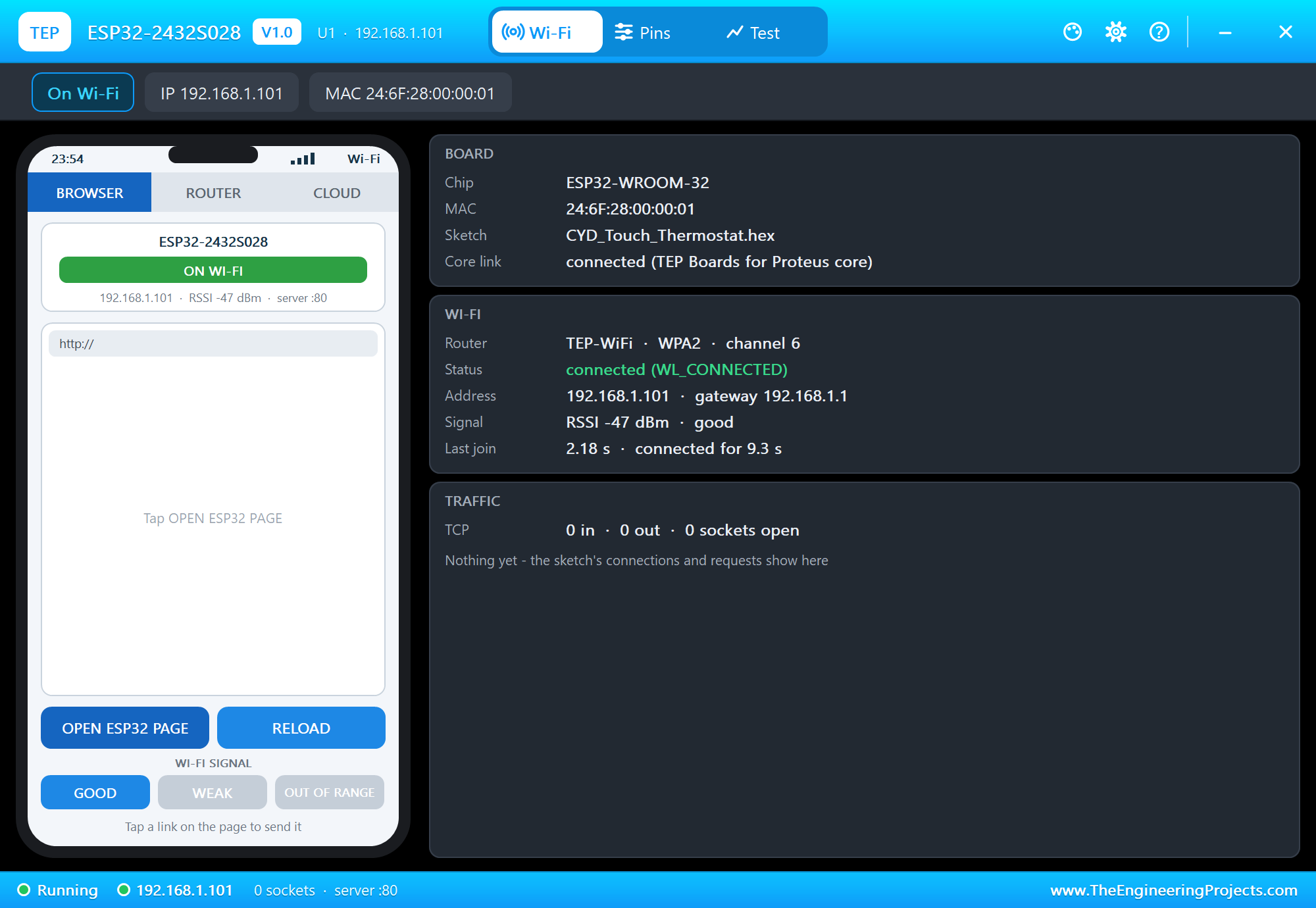
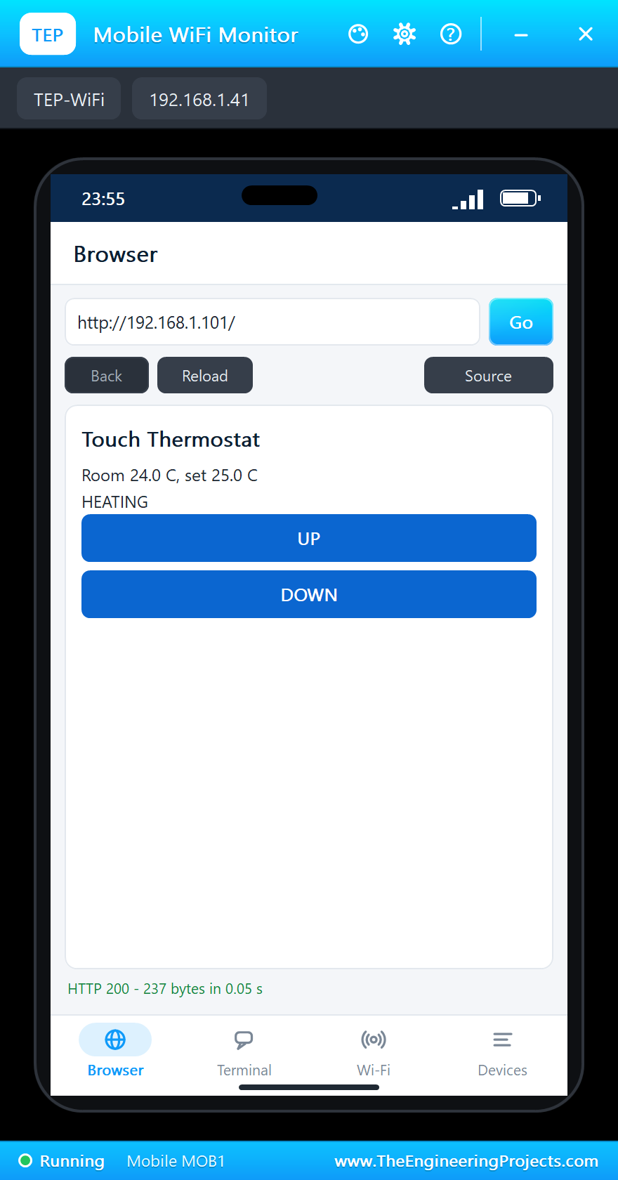
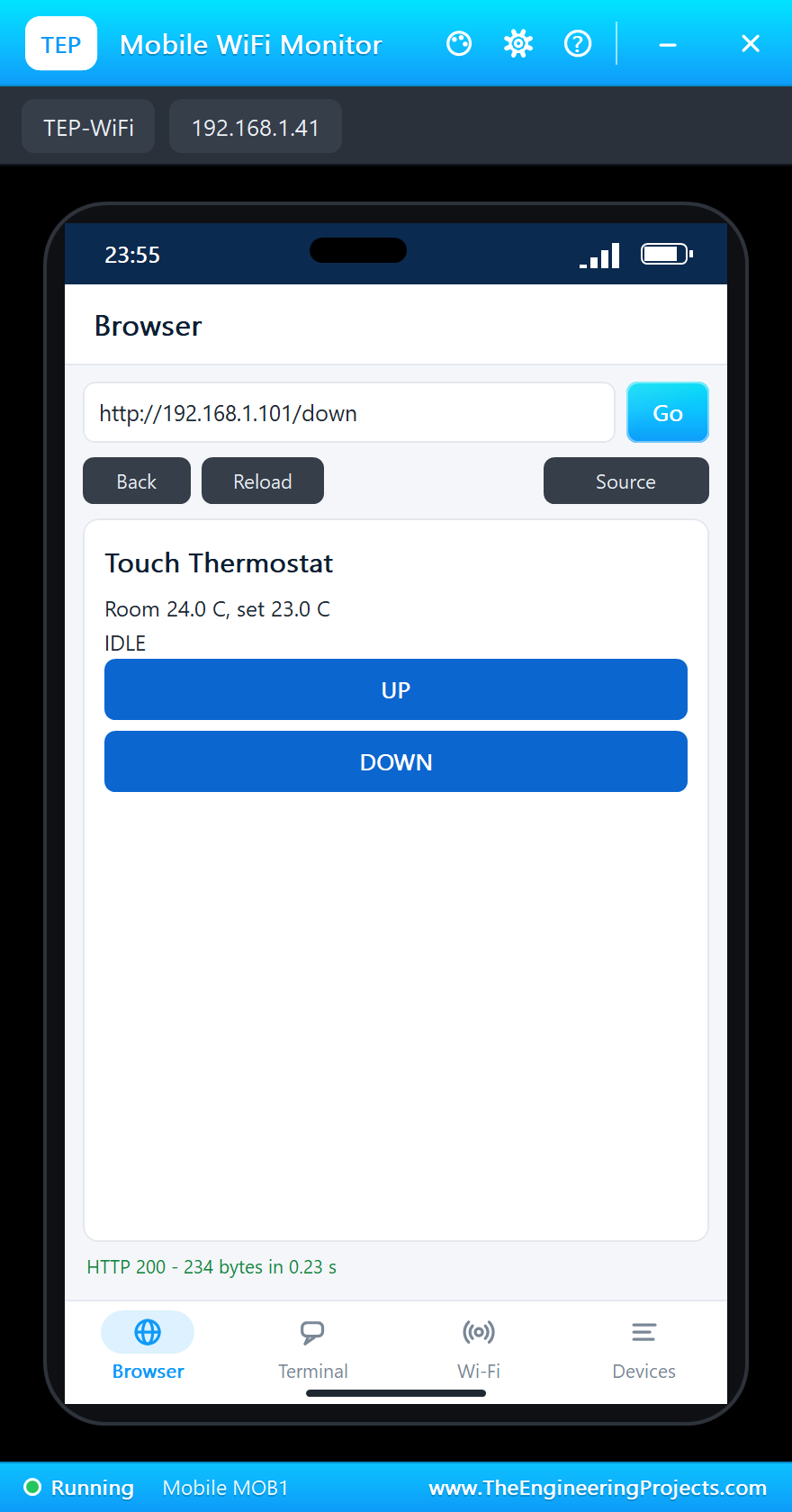
Click ESP32 U1 on the phone. The page shows the room, the set temperature and two links. Tap DOWN twice. The set temperature falls to 23 C, the heater stops and the screen on the wall follows at once:
ON and OFF
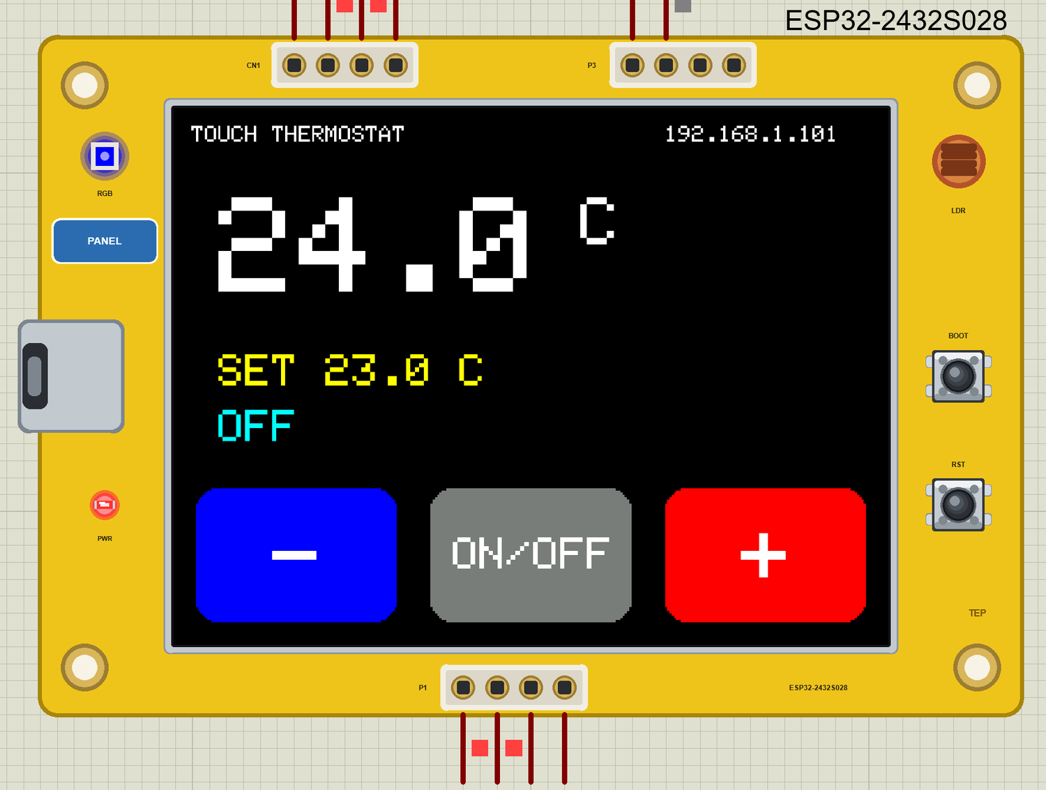
Click the grey ON/OFF button on the glass. The thermostat stops, the heater stays off whatever the room does, and the LED turns blue. Click it again to go back to work:
The built-in serial monitor has followed everything:
Room 19.0 C  set 22.0 C  heating
>> Heater OFF
Room 24.0 C  set 22.0 C  idle
Touch at 264, 199
>> Set temperature 23.0 C
Touch at 264, 199
>> Set temperature 24.0 C
Touch at 264, 199
>> Set temperature 25.0 C
>> Heater ON
Room 24.0 C  set 25.0 C  heating
>> Set temperature 24.0 C
>> Set temperature 23.0 C
>> Heater OFF
Touch at 159, 199
>> Thermostat OFF
Room 24.0 C  set 23.0 C  idle
Touch at 159, 199
>> Thermostat ON
Room 24.0 C  set 23.0 C  idle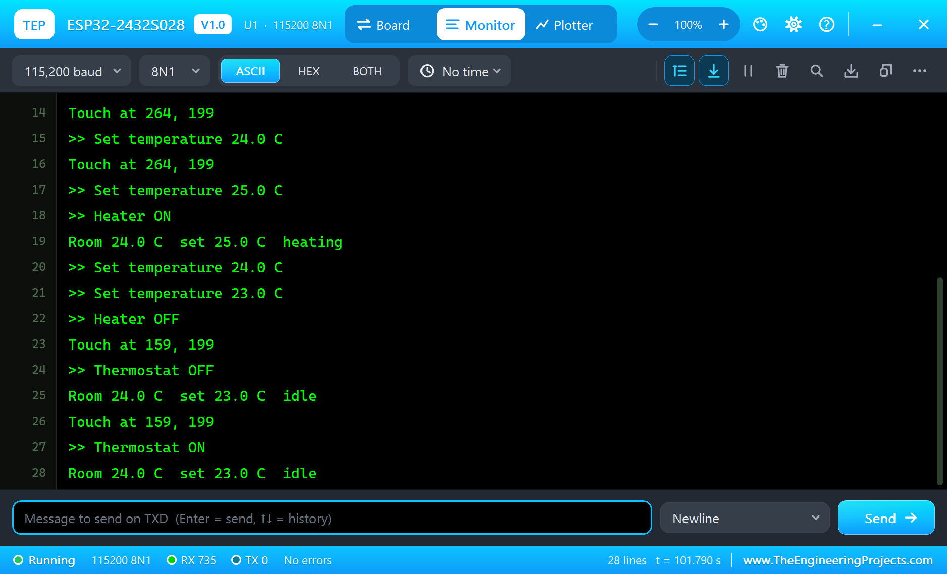
Try It Yourself
- Click COLD or HOT on the DHT22 and watch the thermostat answer.
- Change
BANDto 1.0 and rebuild the sketch: the heater rests longer. - Add a fourth button for a night setting, with its own temperature.
- Dim the backlight with
analogWrite(TFT_BL, 80)after a minute without a touch.
Ideas to Extend the Thermostat
- Add a timer, so that the heat drops at night and comes back before morning.
- Draw a graph of the last hour under the numbers.
- Read the outside temperature from a web service and show it on the screen.
- Add a second relay for a fan or a cooler, with its own limits.
Your Own Sketches
Write the sketch in the Arduino IDE with the board ESP32-2432S028 Cheap Yellow Display (TEP Proteus), use Sketch > Export Compiled Binary and set the part's PROGRAM property to the .hex. The pin names are in the variant, so your sketch stays short. The touch functions of this demo can be copied as they are. On a real board use the same pins with Espressif's "esp32" package, and pick ESP32 Dev Module.
Things to Know Before Using a Real Cheap Yellow Display
- Several versions exist: some boards have two USB ports, and on those the colours can come out inverted.
tft.invertDisplay(true)usually puts that right. - The film needs calibration: print the raw numbers and change the two
map()lines for your own board. - Keep the sensor away from the board: the backlight and the ESP32 warm the PCB, so a DHT22 that sits too close reads high.
- Power the relay from 5 V: use a relay module with a driver, and take its power from VIN. A GPIO cannot drive a coil.
- Mains is dangerous: a real heater runs on mains voltage, so keep that wiring in a closed box and have it checked by somebody qualified.
Properties of the ESP32-2432S028
| Property | What it does |
|---|---|
| PROGRAM | the sketch: a .hex from TEP Boards for Proteus (board "ESP32-2432S028 Cheap Yellow Display") |
| WIFISSID, WIFIPASS | the router in range (TEP-WiFi, 12345678) |
| MONITOR, BAUD, AUTOOPEN | the built-in serial monitor: on, its baud rate (115200), open at Run |
Troubleshooting
- The display stays black: set
TFT_BLHIGH, thenSPI.begin(TFT_SCLK, TFT_MISO, TFT_MOSI, TFT_CS)andtft.begin(). - The picture is upside down: use
tft.setRotation(1). - The touch does nothing: set
XPT2046_IRQas an input and send one command first, as the demo does insetup(). - The touch lands in the wrong place: use the two
map()lines from the demo, aftersetRotation(1). - The phone shows the Welcome page: click ESP32 U1 in its list of devices.
- A number goes wrong above 32767: int is 16 bits in the simulation - use long.
Limitations of the Simulation
- Your sketch gets 8 KB of RAM in the simulation, and there are no FreeRTOS tasks and no second core. A heavy graphics library such as LVGL does not fit.
- The TF card, the speaker's sound and the light on the LDR are not modelled. Bluetooth is not modelled.
- A click holds the pen down for a moment, so hold the mouse button for a long press. Dragging on the glass is not followed.
- ESP32 is a name of Espressif Systems; this library is not made or endorsed by them, by the board's makers or by Labcenter.
- Tested in Proteus 8.5 in October 2026 (the demo as shipped, about 100 s of simulation). Proteus 7 is not supported.
So, that was all about the ESP32-2432S028 Cheap Yellow Display Library for Proteus. I hope it helps you design your own touch panels before you buy a board - the display, the touch screen, the RGB LED and Wi-Fi in one simulation. If you have any questions, ask in the comments and I will help you out. Till the next tutorial, take care and have fun!

Comments
0