


12V Solar Panel Library for Proteus V1.0 (Arduino, INA219)


Hello friends, I hope you all are doing great. Today, I am going to share the new 12V Solar Panel Library for Proteus V1.0, the first part of our new renewable energy series. If you have ever powered a garden light, a weather station, a gate opener or an off-grid Arduino project from the sun, you have met this part: the aluminium-framed 12 V solar panel with its rows of dark-blue cells and two cables with MC4 connectors.
12V Solar Panel Library for Proteus
Latest version: V1.0 (November 2026, this tutorial)
Helping Tools
- Serial Monitor Advance: a serial terminal window for the UART of your board
- Serial Monitor Expert: the serial monitor with extra debugging tools
- LCD Library for Proteus V3.0: 16x2, 20x4 and I2C LCDs to show your readings
This library puts that panel into Proteus as a part of its own - a real one, with its I-V curve. Its current follows the light, its voltage follows the load, and only one point on its curve gives the most power: the maximum power point. It also does the things that surprise people with real panels: the voltage collapses when a load asks for more than the light makes, a single leaf takes half the panel out through a bypass diode, and a cloudy sky leaves only a fifth of the power. The demo measures it with our INA219 current sensor from an Arduino UNO V4.0.
NOTICE: a solar panel looks like a battery that charges in the sun - but it behaves nothing like one. Our team put a lot of effort into building a panel that behaves like the real thing: 36 cells with their I-V curve, the two bypass diodes, the heat, the shade and the light. Your feedback is the fuel that keeps us going, so please tell us what you think in the comments below or in the Motor Driver board of our forum. And if our free libraries help you, you can buy us a coffee. So, let's get started with the 12V Solar Panel Library for Proteus V1.0:
What is a 12V Solar Panel?
A solar panel is a string of photovoltaic cells: thin slices of silicon that turn light into current. One monocrystalline cell gives about 0.6 V with no load, whatever its size; its size sets the current. A "12 V" panel has 36 cells in series, which gives about 21.6 V open-circuit - enough to charge a 12 V battery, which needs up to 14.4 V, even when the panel is hot and the cables lose a little.
| 12 V solar panel (the model, 20 W) | |
|---|---|
| Cells | 36 monocrystalline cells in series, as two strings of 18, each with a bypass diode |
| Open circuit (Voc) | 21.6 V at 1000 W/m2 and 25 C |
| Short circuit (Isc) | 1.22 A on the 20 W panel (61 mA per rated watt) |
| Maximum power point | about 17.6 V - exactly the rated watts at 1000 W/m2 and 25 C |
| Sizes | 10, 20, 50 or 100 W (property WATTS) |
| Properties | WATTS, IRRADIANCE (W/m2), AMBIENT (C) |
The I-V Curve and the Maximum Power Point
A battery holds its voltage and gives whatever current the load wants. A solar panel does almost the opposite: the light decides its current, and the load decides where on its curve it sits. Ask for a little current and the voltage stays high, near Voc. Ask for more and the voltage drops slowly - until the current gets close to what the light makes, and then it falls off a cliff. Power is volts times amps, so it is small at both ends and peaks at the knee of the curve: the maximum power point (MPP). On a 20 W panel in full sun, that is about 17.6 V and 1.14 A.
Why the Label Says 12 V
The "12 V" on the label is the battery it is meant to charge, not the panel's voltage. The datasheet numbers are for the standard test conditions (STC): 1000 W/m2 of sunlight and cells at 25 C. Real cells in the sun run 20 to 30 degrees warmer, and every degree costs about 0.4 % of the power, so on a sunny day a panel gives about 80 % of its label.
What's New in 12V Solar Panel Library for Proteus V1.0
- A part of its own - just the panel: the aluminium frame, 36 dark-blue cells on a white backsheet and the red and black cables with MC4 connectors.
- A real I-V curve in the circuit: the single-diode model for every cell, fitted so the panel gives exactly its rated watts at STC.
- Light, heat and shade: the current follows the light, the voltage falls 0.33 % a degree, a leaf or a shadow switches on the bypass diodes.
- Honest edge cases: the voltage collapses under too much load, current flows back in at night, and a reversed source drives the bypass diodes.
- A pop-up window with four pages - Panel, Graphs, Event log and Check - with the live I-V and P-V curves, the maximum power point and the sky over the panel.
- An A3 demo on our Arduino UNO V4.0 with our INA219 and its DC load: the volts, the amps, the watts and the best point on the serial monitor.
The 12V Solar Panel in Proteus
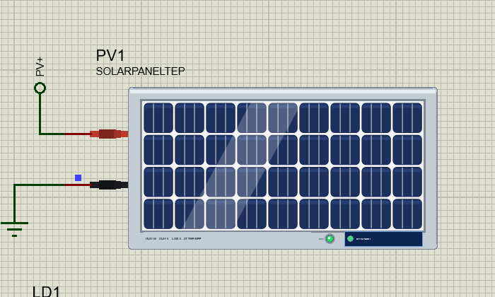
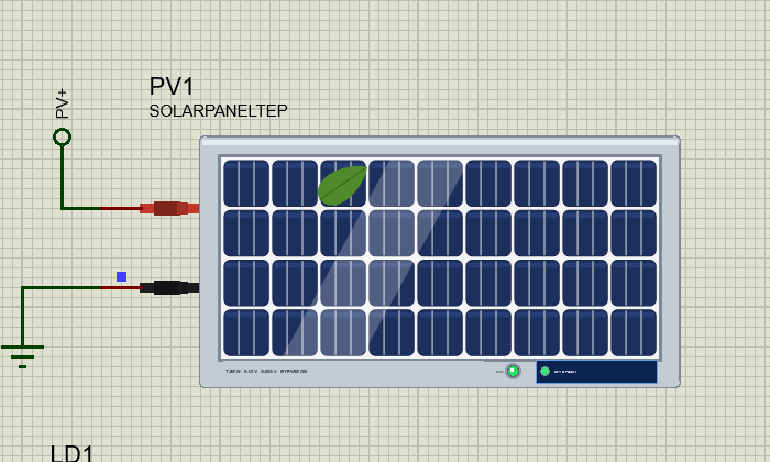
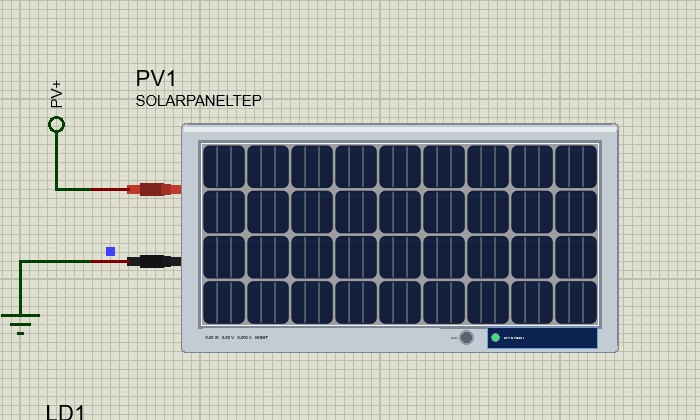
Search solar in Pick Devices; the device SOLARPANELTEP is in TEPSOLAR.LIB (category Electromechanical, Renewable Energy) and its model is TEPSOLAR.DLL. The symbol is just the panel: the silver aluminium frame, the glass over 36 pseudo-square cells (9 by 4) on a white backsheet with their busbars, and the red and black cables with their MC4 connectors leading to the + and - pins.
At Run the cells come alive: their glare follows the light, they go dark at night, and a leaf or a pole's shadow lies on them when you choose one. On the frame's bottom rail the value line shows the watts, volts, amps and the state, the OUT LED lights green while the panel delivers power, and OPEN PANEL opens the pop-up. The value line, the LED, the button and the shade on the cells are TEP additions; a real panel has none of them. The sun, the clouds and the night are drawn in the pop-up.
The Pins and the Properties
| Pin | What the model does with it |
|---|---|
| + | the red cable: the current comes out here |
| - | the black cable: the return |
| Property | Default | What it does |
|---|---|---|
| WATTS | 20 | the panel: 10, 20, 50 or 100 W at STC |
| IRRADIANCE | 1000 | the light at the start, in W/m2 (0 to 1200) |
| AMBIENT | 25 | the air in C (-20 to 50); the cells start at it and warm in the sun |
Download 12V Solar Panel Library for Proteus
Click the button below to download 12V-Solar-Panel-Library-for-Proteus-v1.0.zip (about 1.2 MB, without the source code of the models):
12V Solar Panel Library for Proteus V1.0- README.txt: installation, the demo, the wiring, the properties, real hardware, troubleshooting and the limits.
- Proteus Library Files:
TEPSOLAR.LIBandArduinoV4TEP.LIBfrom our Arduino Library for Proteus V4.0. - Proteus Model Files:
TEPSOLAR.DLLandTEPARDUINO.DLL. - Proteus Simulation:
12V-Solar-Panel-INA219-ArduinoUnoV4.pdsprj,Solar_Demo.hexand copies of the DLLs. - Arduino Code:
Solar_Demo.ino(only the Wire library of the Arduino core).
Good to know: the demo's INA219 and its DC electronic load are our INA219 Current Sensor library, a separate download that is not in this zip. Get it from its own article, the INA219 Current Sensor Library for Proteus, and install TEPINA219.LIB and TEPINA219.DLL the same way.
No Proteus yet? Read How to Download and Install Proteus 7 and 8. New to libraries? Follow How to Install a New Library in Proteus.
How to Install 12V Solar Panel Library for Proteus
- Close Proteus and extract the whole zip file, for example to your Desktop.
- Copy
TEPSOLAR.LIBandArduinoV4TEP.LIBfrom Proteus Library Files into the LIBRARY folder of Proteus (usuallyC:\Program Files (x86)\Labcenter Electronics\Proteus 8 Professional\LIBRARY). - Copy
TEPSOLAR.DLLandTEPARDUINO.DLLfrom Proteus Model Files into the MODELS folder. The two Arduino files are the ones of our Arduino Library V4.0; if you have it, they are the same. - Install the INA219 Current Sensor library the same way if you do not have it yet.
- Delete
TEPSOLAR.IDXfrom the LIBRARY folder if it is there. - Start Proteus, press P and search for solar.
Tip: keep the Proteus Simulation folder together, because the project needs its .hex file and the DLLs beside it. The library is tested in Proteus 8.5; Proteus 7 is not supported.
The Demo Circuit
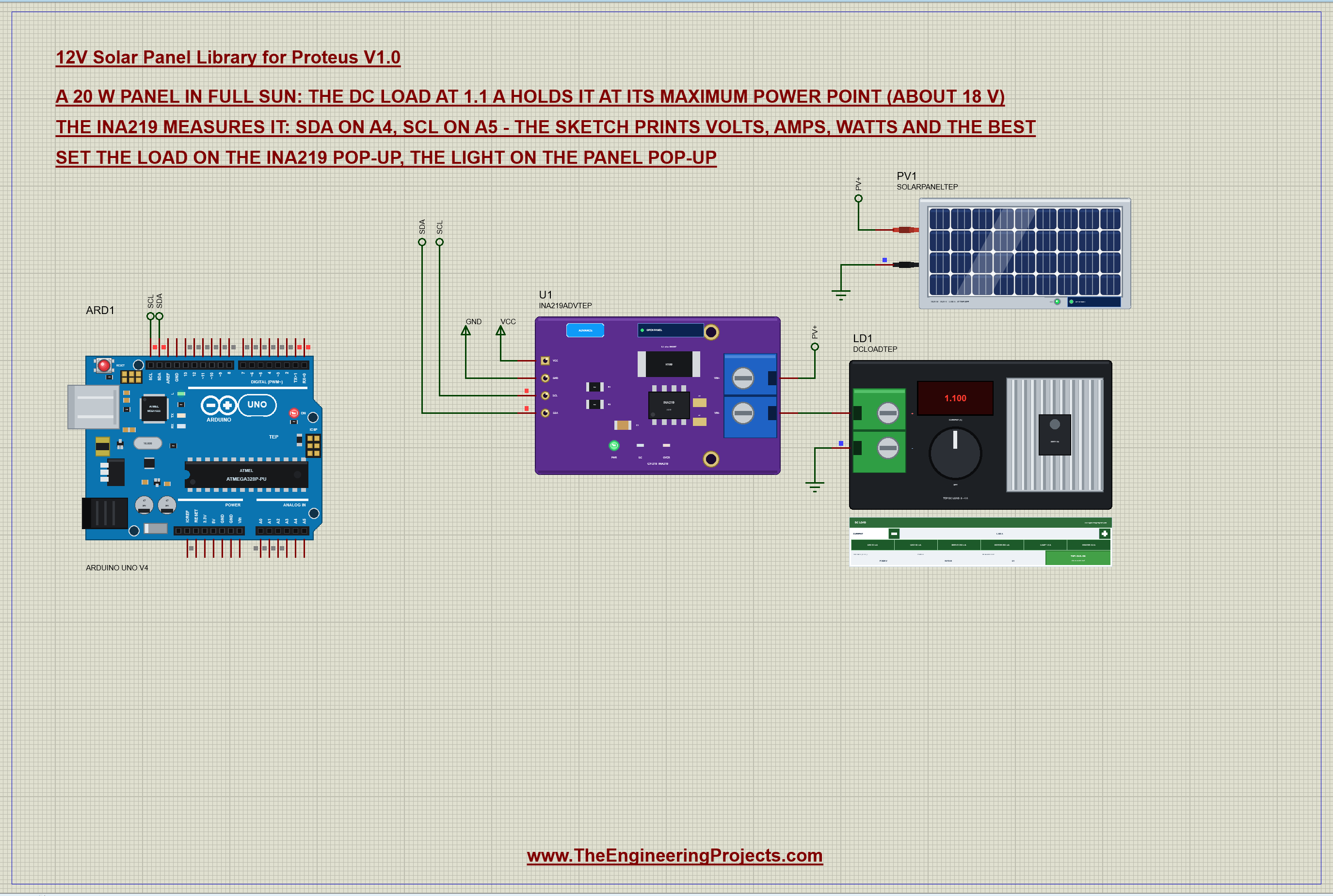
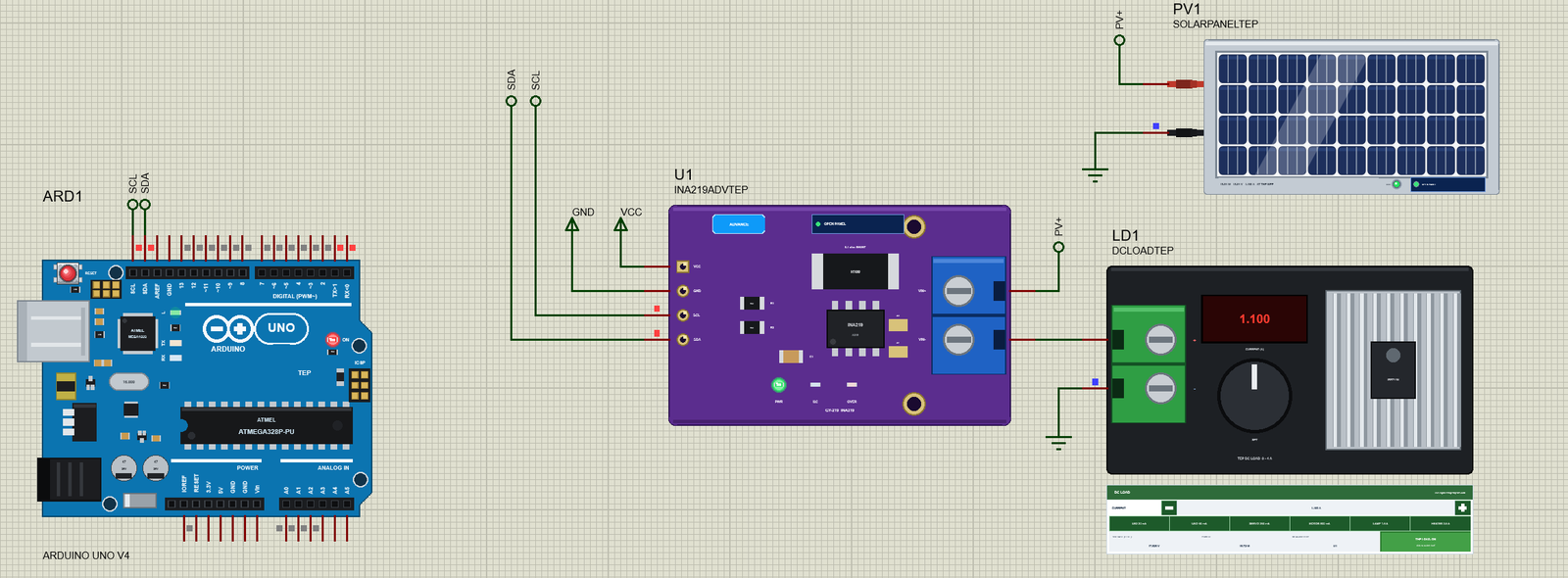
Open 12V-Solar-Panel-INA219-ArduinoUnoV4.pdsprj. ARD1 is an Arduino UNO V4.0 from our Arduino UNO Library for Proteus V4.0, running Solar_Demo.hex with its serial monitor built in. PV1 is a 20 W panel in full sun. Its + goes through U1, our INA219 in its pop-up version, and on into LD1, the INA219 library's electronic load, set to 1.1 A - the current of this panel's maximum power point.
| Part | Pin | Goes to |
|---|---|---|
| PV1 | + | the PV+ net label, which joins the INA219's VIN+ |
| INA219 | VIN- | the DC load's + (a straight wire) |
| INA219 | SDA, SCL | the UNO's A4 and A5 (SDA and SCL labels) |
| PV1, LD1 | - | ground |
Why an INA219 and a DC Load?
A panel is easy to measure badly. Its open-circuit voltage says nothing about its power, and a fixed resistor only shows one point on its curve. The INA219 measures the real current through its 0.1 ohm shunt and the voltage at the same time, and the DC electronic load draws exactly the current you set - so stepping the load walks the panel along its I-V curve, just like a solar test bench. The panel's own 21.6 V would be too much for an analog pin anyway; the INA219 measures up to 26 V.
The Arduino Code
The sketch needs only the Wire library of the Arduino core. New to Arduino? Start with Arduino Tutorial for Beginners and Introduction to Arduino UNO. It talks to the INA219 at its default address:
const byte INA = 0x40;
const float SHUNT_OHM = 0.1;
Every INA219 register is 16 bits, most significant byte first: write the register's number, then read two bytes:
int16_t readReg(byte reg) {                    // a 16-bit register, MSB first
  Wire.beginTransmission(INA);
  Wire.write(reg);
  Wire.endTransmission();
  Wire.requestFrom(INA, (byte)2);
Volts, Amps and Watts
The shunt register counts in 10 uV steps, so the current is the shunt volts over 0.1 ohm. The bus register counts in 4 mV steps in its top 13 bits and gives the load's volts; the panel's own volts are that plus the shunt's small drop. The sketch reads the bus before and after the shunt:
  const float bus1 = ((uint16_t)readReg(0x02) >> 3) * 0.004;    // 4 mV a step
  const float shuntV = readReg(0x01) * 0.00001;                 // 10 uV a step
  const float bus2 = ((uint16_t)readReg(0x02) >> 3) * 0.004;
  const bool steady = fabs(bus2 - bus1) < 0.05 + 0.01 * bus1;    // the panel did not change during the reads
Why twice? The registers are read one after the other. If the load changes between them, the volts come from before the change and the amps from after it, and their product is a power the panel never gave. Our first test run caught exactly that: a "best" of nearly 24 W from a 20 W panel. Now a reading taken while the panel changes is marked and does not count:
if (steady && watts > bestW) { bestW = watts; bestV = volts; bestA = amps; } if (!steady) Serial.print(F(" - changing"));
else if (amps > 0.005 && volts < 2.0) Serial.print(F(" - collapsed: the load wants more than the light makes"));The Report Loop
The loop never waits: it reads the serial commands and reports when the next report is due, by default every second:
if ((long)(millis() - nextAt) >= 0) { nextAt = millis() + rateMs; report(); }rate 500 changes that interval (200 to 5000 ms), best prints the best point so far and reset forgets it:
  if (!strncmp(s, "rate ", 5)) {
    rateMs = constrain(atoi(s + 5), 200, 5000);
The sketch also writes the INA219's calibration register once, so the chip's own Current and Power registers work too - the INA219's pop-up then shows them:
writeReg(0x05, 4096); // the calibration: 0.1 mA a step in the Current registerThe HEX file is in the package. To change the sketch, open it in the Arduino IDE and export the compiled binary, as in How to get the HEX file from Arduino. It needs 8,990 bytes of flash (28 % of the UNO) and 496 bytes of RAM.
Running the Demo
Press Run. The UNO's serial monitor, the panel's pop-up and the INA219's pop-up open over the schematic; move them aside. The sketch introduces itself and starts reporting every second:
12V Solar Panel demo - The Engineering Projects
The panel feeds the DC load through the INA219 (0x40 on A4 / A5, 0.1 ohm shunt). Set the load on its pop-up.
Commands: best | reset | rate 1000 | help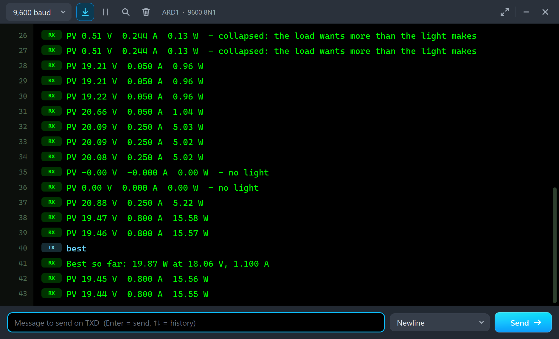
At the Maximum Power Point
In full sun with the load at 1.1 A, the panel sits right at its best: "AT THE MPP - 18.06 V x 1.100 A = 19.86 W (1000 W/m2, cells 25 C): the most this light gives". That is the label's 20 W, because the cells are still at 25 C.
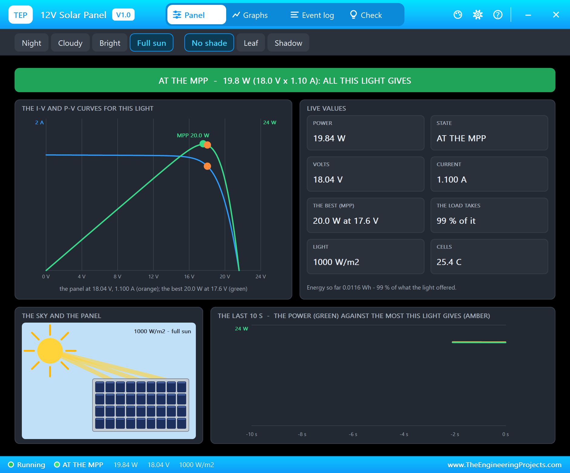
The pop-up has the look of our TEP Serial Monitor Advance for Proteus and four tabs: Panel, Graphs, Event log and Check. The Panel page draws the I-V curve (blue) and the P-V curve (green) for the light of the moment, with the maximum power point in green and the panel's real operating point in orange - here right on the peak. Beside them are eight live values, and below them the sky and the panel: the sun, its beams and the shade, if any. The trace shows the power against the most the light can give over the last 10 seconds.
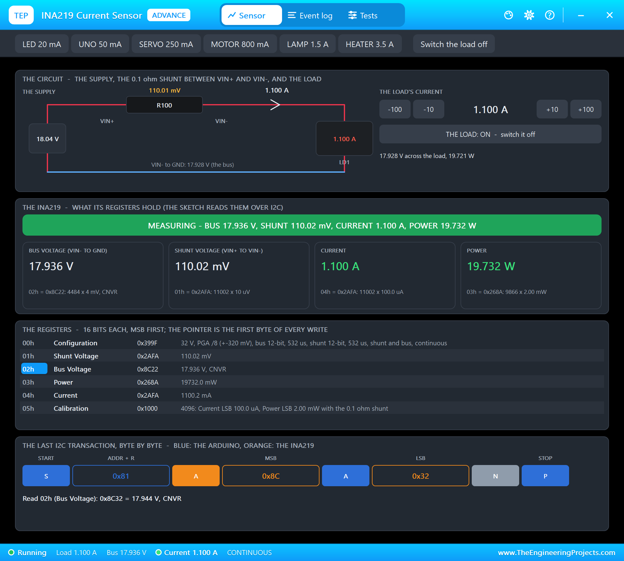
The INA219's pop-up sees the same from the measuring side: "MEASURING - BUS 17.936 V, SHUNT 110.02 mV, CURRENT 1.100 A, POWER 19.732 W". Its bus voltage is taken after the shunt, so it is about 0.11 V lower than the panel's own 18.04 V. Its toolbar holds the DC load's presets, which is how we change the load in the next steps.
A Smaller Load
Click the MOTOR 800 mA preset. The panel answers with a higher voltage but less power: "OUTPUT 19.70 V x 0.800 A = 15.77 W - 79 % of the 20.0 W it could give at 17.6 V".
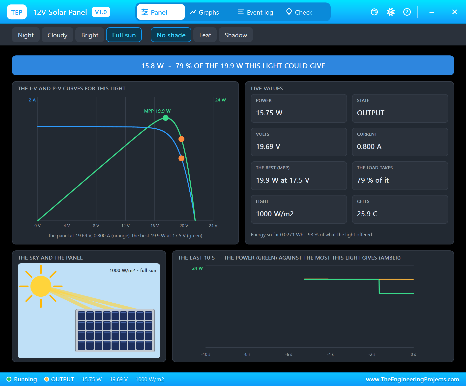
On the curves the orange point has slid right, past the peak, towards the open-circuit end. A fifth of the power the light offers is simply not taken. This is what happens when a battery or a fixed load sets the operating point instead of the panel's best.
Asking for Too Much
Now click LAMP 1.5 A - more than the 1.22 A the light makes:
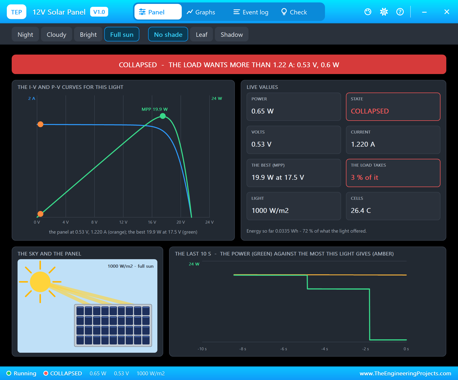
The voltage falls off the cliff: "COLLAPSED - the load wants more than the 1.22 A this light makes: 0.53 V x 1.220 A = 0.65 W". The panel gives all the current it has, but at almost no voltage, so the power is close to nothing. A motor or a DC-DC converter that pulls too hard from a panel does exactly this - and the more it pulls, the less it gets.
A Leaf on One Cell
Back to MOTOR 800 mA, and click Leaf on the panel's pop-up. A leaf now covers one cell of the top string:
The cells in a string are in series, so the shaded cell limits all 18 cells of its string to 20 % of the current: "A LEAF on one cell (set on the panel): its string makes 20 % - peaks 9.5 W at 8.4 V and 4.2 W at 18.3 V". The load wants 0.8 A, more than that string can carry, so its bypass diode takes over: "BYPASS DIODE ON - a shaded string is bypassed: 9.44 V x 0.800 A = 7.55 W (the best: 9.5 W at 8.4 V)".
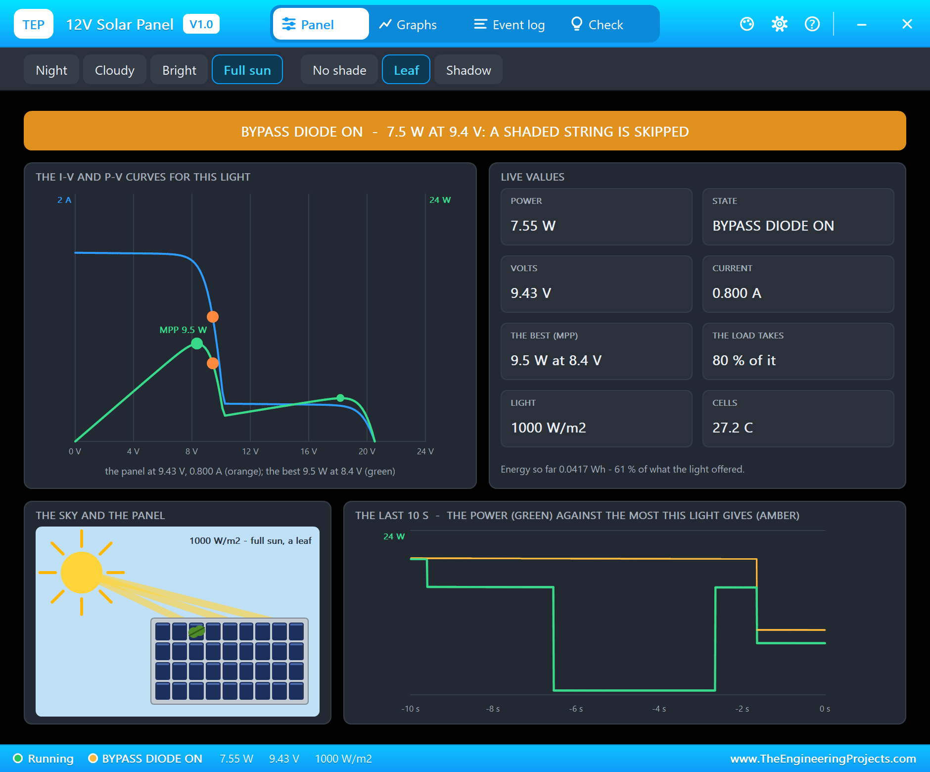
The curves show what a single leaf does. The I-V curve gets a step, and the P-V curve two peaks: one at full voltage with a starved current, one at half voltage with the full current. One leaf, one cell in 36, has taken more than half of the panel's power. Without the bypass diodes it would be worse still - the whole panel would be limited to the shaded cell's current.
A Shadow Across Both Strings
Click Shadow: a pole's shadow now crosses the panel, darkening a cell in each string:
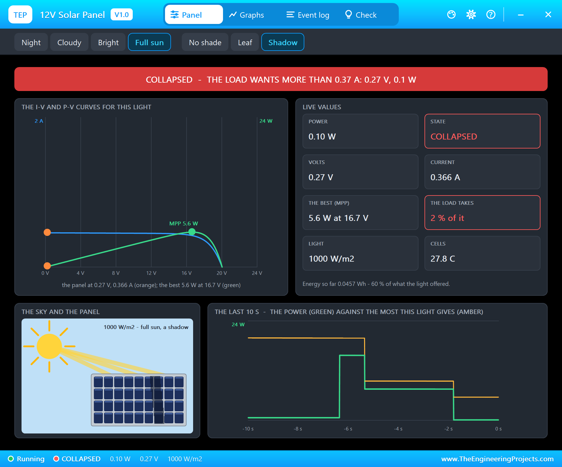
This time no bypass diode can help, because both strings are starved: "A POLE'S SHADOW across both strings (set on the panel): each makes 30 % - the best now 5.6 W at 16.7 V". The 0.8 A load is now too much and the panel collapses: "COLLAPSED - the load wants more than the 0.37 A this light makes: 0.27 V x 0.366 A = 0.10 W".
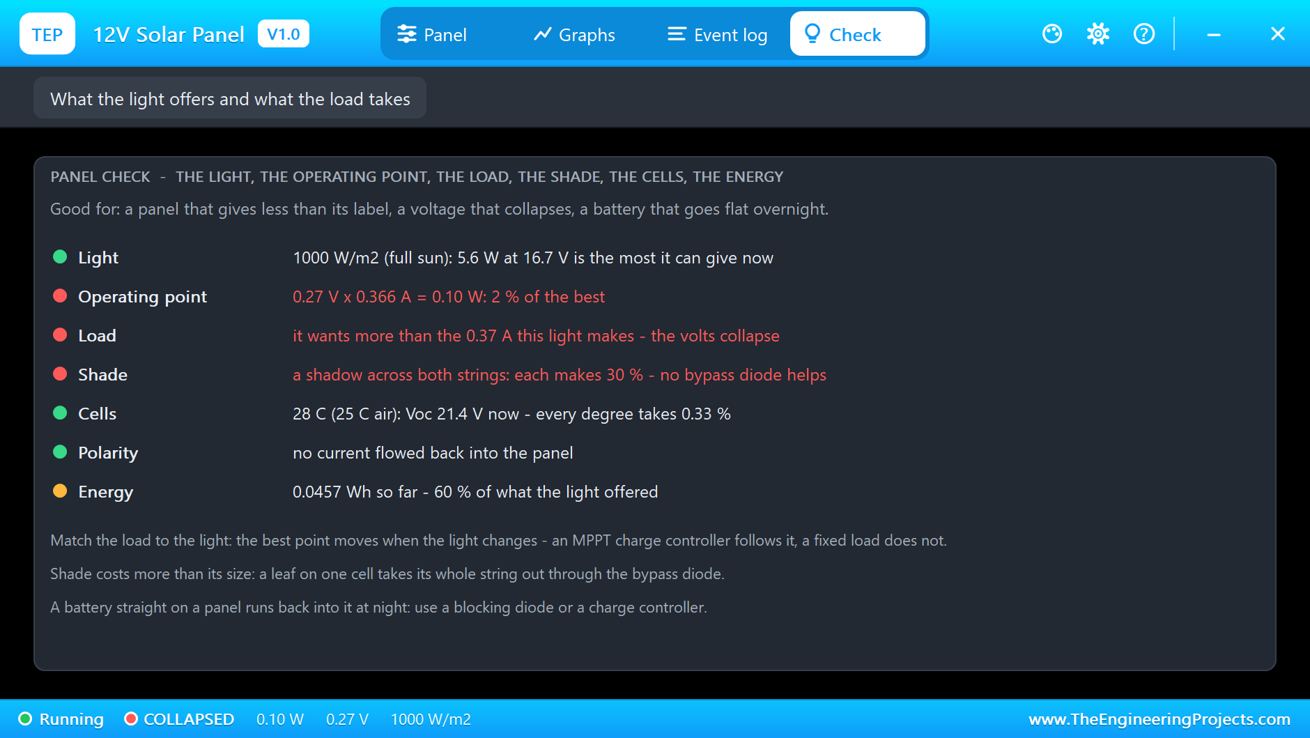
The Check page goes through the light, the operating point, the load, the shade, the cells, the polarity and the energy, each with a coloured dot. Here three rows are red: "0.27 V x 0.366 A = 0.10 W: 2 % of the best", "it wants more than the 0.37 A this light makes - the volts collapse" and "a shadow across both strings: each makes 30 % - no bypass diode helps".
Clouds, Bright Light and Night
Click No shade and then Cloudy. The light drops to 200 W/m2, and so does the panel: "LIGHT 200 W/m2 - cloudy (set on the panel): the most it can give now is 3.6 W at 16.3 V". Even the SERVO 250 mA preset is too much now:
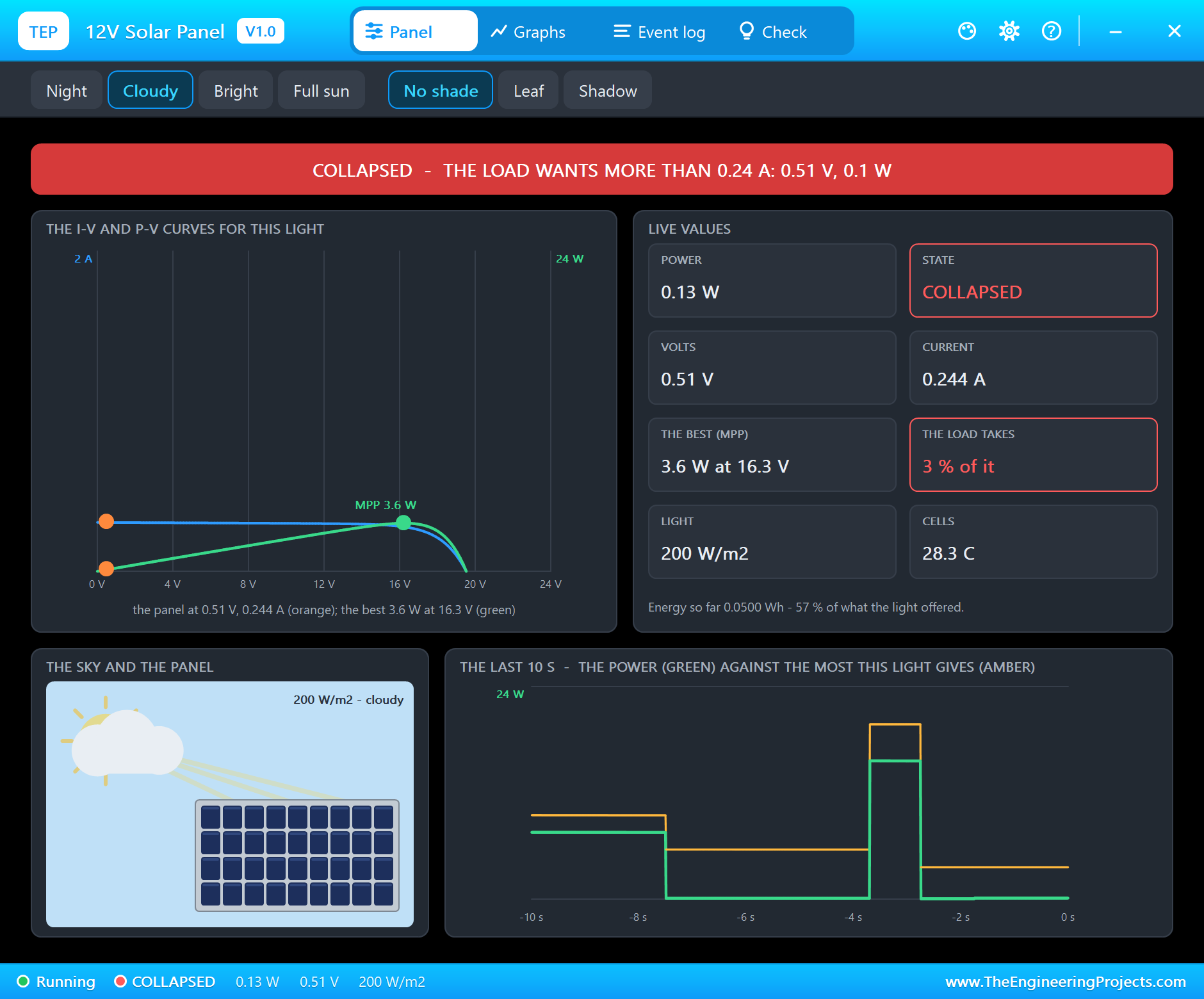
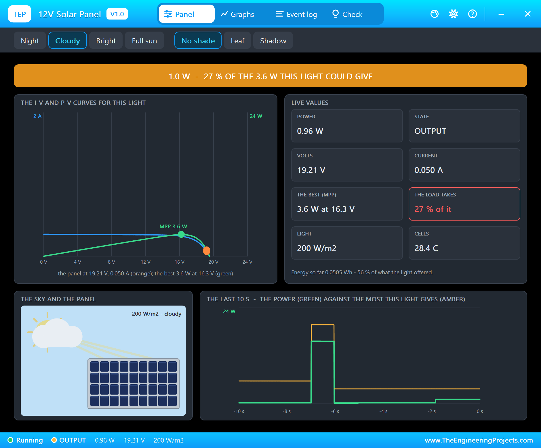
"COLLAPSED - the load wants more than the 0.24 A this light makes: 0.51 V x 0.244 A = 0.13 W". Notice that the voltage on the curve hardly changed - the open-circuit voltage only drops a little in weak light - but the current is a fifth of what it was. With the UNO 50 mA preset the panel works again, but far from its best: "OUTPUT 19.21 V x 0.050 A = 0.96 W - 27 % of the 3.6 W it could give at 16.3 V".
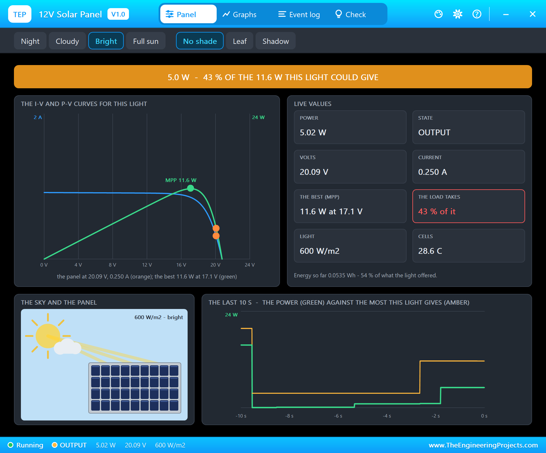
Click Bright (600 W/m2) and the 250 mA preset: "OUTPUT 20.10 V x 0.250 A = 5.02 W - 43 % of the 11.6 W it could give at 17.1 V". Every light has its own best current, and a fixed load is right for at most one of them. That is the job of an MPPT charge controller: it keeps moving the operating point to the peak as the light changes.
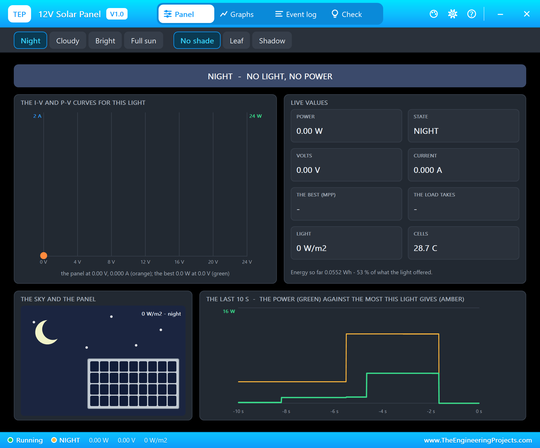
Finally, Night: "NIGHT - no light: 0.00 V, the panel makes nothing". The pop-up's sky turns to the moon and the stars, and on the sheet the cells go dark.
Back in full sun with the 800 mA load, the monitor shows the whole story - and the best point it saw:
PV 0.51 V  0.244 A  0.13 W  - collapsed: the load wants more than the light makes
PV 19.21 V  0.050 A  0.96 W
PV 20.09 V  0.250 A  5.03 W
PV 0.00 V  0.000 A  0.00 W  - no light
PV 20.88 V  0.250 A  5.22 W
PV 19.47 V  0.800 A  15.58 W
best
Best so far: 19.87 W at 18.06 V, 1.100 A
Graphs and the Log
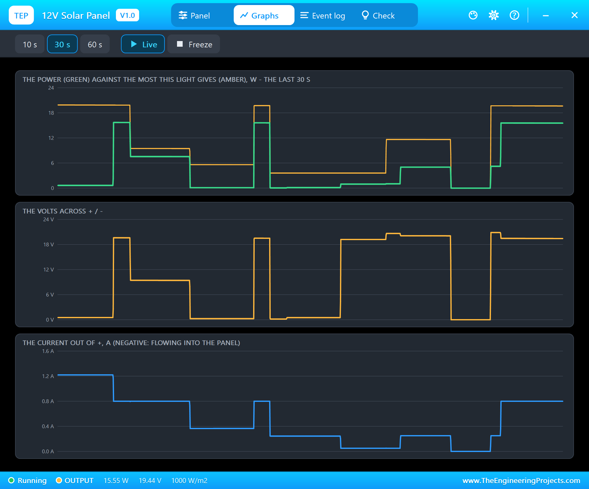
Graphs draws the power against the most the light can give, the volts and the current over the last 10, 30 or 60 seconds. The gap between the green power and the amber best is the energy left on the table; each drop of the volts to nearly zero is a collapse.
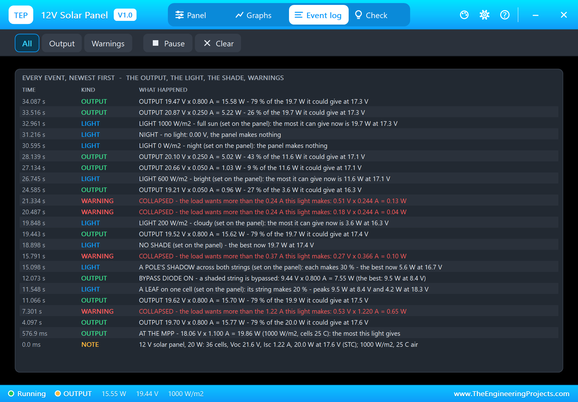
The Event log keeps every operating point with its share of the best, every change of the light and the shade with the new best point, and the warnings. Filter it to Output or Warnings, pause it, or clear it. More warnings you may meet: REVERSE CURRENT when something pushes current into the panel, REVERSED when a source is connected the wrong way, and HOT when the cells pass 75 C.
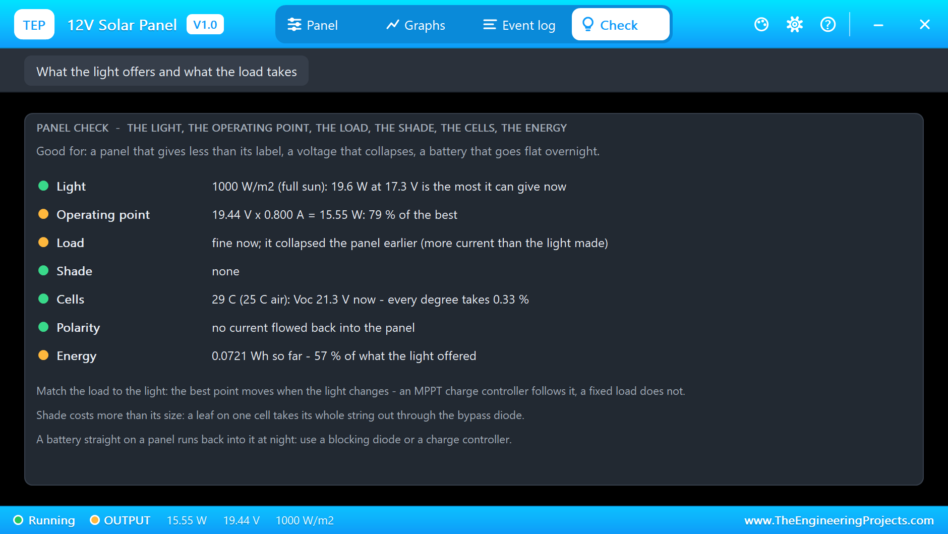
At the end of the run the Check page sums it up: "19.44 V x 0.800 A = 15.55 W: 79 % of the best", the Load row remembers that it collapsed the panel earlier, the cells have warmed to 29 C ("Voc 21.3 V now"), and the energy row: "0.0721 Wh so far - 57 % of what the light offered". A fixed load let more than 40 % of the available energy go.
How the Model Works
Each of the 36 cells follows the standard single-diode model: a current source for the light, a diode, a series and a shunt resistance. Its numbers are fitted so the panel gives exactly its rated watts at 1000 W/m2 and 25 C, with 21.6 V open-circuit and about 17.6 V at the maximum power point. The cells form two strings of 18, each with a bypass diode; a string's current is its weakest cell's.
At every Newton step of the simulation the model works out the panel's current at that step's voltage and puts the tangent of its I-V curve into the circuit, so the panel and the load are solved together, wherever the load takes it. In transient the cells' capacitance (1 uF on a 20 W panel) is in the circuit too, which lets a too-heavy load collapse the voltage smoothly. The cells warm towards the air plus 31 C in full sun over about three minutes, and their voltage falls 0.33 % a degree.
We checked the model on a PC with 15 automatic tests: the 10, 20, 50 and 100 W panels give 21.60 V open-circuit, 61 mA per watt short-circuit and exactly their rated watts at 17.60 V; 200 W/m2 gives 3.66 W; cells at 56 C give 12.8 % less; a 12.6 V battery pushes 6.2 mA into the dark panel; a leaf gives two peaks, 9.57 W and 4.23 W; a pole's shadow leaves 5.67 W; and the panel solves with a resistor and with the DC load at 0.8, 1.1 and 1.5 A. The demo project is read back from disk with 69 checks.
Troubleshooting
- COLLAPSED: the load wants more current than the light makes - a smaller load, more light or a bigger panel.
- OPEN CIRCUIT: nothing takes the power - check the load's wiring.
- BYPASS DIODE ON: a shaded string is bypassed - remove the shade.
- REVERSE CURRENT: something pushes current into the panel, such as a battery at night - fit a blocking diode or use a charge controller.
- REVERSED: a source is connected the wrong way round - check + and -.
- The panel is not simulated:
TEPSOLAR.DLLis missing from MODELS and from the project folder. - No INA219 or no load: install our INA219 library (
TEPINA219.LIBandTEPINA219.DLL). - No UNO or no monitor:
TEPARDUINO.DLLis missing; a closed monitor opens again with a click on the UNO's USB port. - No pop-up: click OPEN PANEL on the panel's frame, or turn "Open the panel at Run" on in its Settings.
Things to Know Before Wiring a Real Solar Panel
- Expect less than the label: the watts are for 1000 W/m2 and cells at 25 C; on a sunny day expect 70 to 85 % (warm cells, the angle, dust).
- Point it at the sun: a tilt of about 30 degrees towards the equator is a good start - and keep it out of shade, because a leaf on one cell costs half the panel.
- Use a charge controller: a battery straight on a panel runs back into it at night and is overcharged by its 21 V in the sun.
- Measure it safely: 21.6 V is too much for an analog pin - use a current sensor such as the INA219 and a 1:5 divider for the volts.
- Mind the polarity: a battery connected the wrong way drives large currents through the bypass diodes.
Limitations of the Simulation
- Not modelled: the angle of the sun (set the light instead), spectral effects, cell cracks and hot spots, the slow loss of power over the years, and a cell only partly shaded (a shaded cell is a whole cell at a share of the light).
- The value line, the OUT LED, the OPEN PANEL button and the shade on the cells are TEP additions.
- The model is our own implementation of the standard single-diode model, fitted to the typical data of 12 V monocrystalline panels; this library is not made or endorsed by any panel maker, Arduino or Labcenter.
- Licences: the demo HEX contains the Arduino AVR core 1.8.6 (LGPL) with its Wire library; the sketch is included and the README gives the source link. The INA219 and the DC load of the demo are our separate library.
- Tested in Proteus 8.5 in October 2026 with the demo as shipped: the maximum power point, 0.8 A, 1.5 A, a leaf, a shadow, cloudy, bright, night, and all four pages of the pop-up. Proteus 7 is not supported.
So, that was all about the 12V Solar Panel Library for Proteus V1.0. I hope it helps you plan your solar projects and see why a charge controller that tracks the maximum power point is worth it. If you have any questions, ask in the comments and I will help you out. Till the next tutorial, take care and have fun!

Comments
0