


Car Door Lock Actuator Library for Proteus V1.0 (12V Central Locking)


Hello friends, I hope you all are doing great. Today, I am going to share the new Car Door Lock Actuator Library for Proteus V1.0. Press the lock button on a car key, and in every door a small black box goes "clack": that is the door lock actuator, the motor of the central locking. The same actuator is sold on its own for a few dollars in every aftermarket central-locking kit, and makers use it for drawer and cabinet locks, pet doors, escape-room props and small linear jobs where a strong 20 mm push or pull is enough.
Car Door Lock Actuator Library for Proteus
Latest version: V1.0 (November 2026, this tutorial)
Helping Tools
- Serial Monitor Advance: a serial terminal window for the UART of your board
- Serial Monitor Expert: the serial monitor with extra debugging tools
- LCD Library for Proteus V3.0: 16x2, 20x4 and I2C LCDs to show your readings
This library puts that actuator into Proteus as a part of its own. Its motor is in the circuit, its gears and rack move a steel rod 20 mm in or out, the rod stops dead at each end and the motor stalls there, and its position switch tells the controller where the rod is. You can put it on the door lock, on the bench or on a jammed lock, and even move the rod by hand as the key or the knob would. The demo drives it from an Arduino UNO V4.0 through our two-channel relay module, wired as the classic central-locking circuit.
NOTICE: a door lock actuator looks like the simplest motor there is - two wires and a rod. Our team put a lot of effort into building one that behaves like the real thing: the stroke that takes a fifth of a second, the stall at the stop, the position switch, the lock's spring and a lock that jams. Your feedback is the fuel that keeps us going, so please tell us what you think in the comments below or in the Motor Driver board of our forum. And if our free libraries help you, you can buy us a coffee. So, let's get started with the Car Door Lock Actuator Library for Proteus V1.0:
What is a Car Door Lock Actuator?
A door lock actuator is a small permanent-magnet DC motor in a plastic case, with a gear train and a rack that turn its rotation into a straight movement of a steel rod. The rod is linked to the door's lock. Apply 12 V one way and the rod pulls in; reverse the polarity and it pushes out. The car's body controller decides which way is "lock" by the way the actuator is mounted; in our model, M+ positive pulls the rod in and locks.
| Wire | What it is |
|---|---|
| M+ | the motor: positive here pulls the rod IN (lock) |
| M- | the motor: positive here pushes the rod OUT (unlock) |
| S | the position switch's common |
| SL | closed to S while the rod is in (locked) |
| SU | closed to S while the rod is out (unlocked) |
Master and Slave Actuators
Central-locking kits come with two kinds. The 2-wire or "slave" actuator has only the motor. The 5-wire or "master" actuator adds a small switch that the rod moves: it tells the controller whether the door is locked or unlocked, also when someone turns the key or presses the knob. That is how the other doors follow the driver's door. This library models the 5-wire type; leave the three switch wires open and you have the 2-wire one.
Why It Only Needs a Pulse
The actuator has no limit switch on its motor and no speed control. The rod simply runs to the end of its travel and stops against the case. The motor stalls there: it cannot turn, so it makes no back-EMF, and only its winding resistance limits the current. That is why a car's controller gives it a pulse of about 0.3 to 0.5 seconds and then cuts the power - enough for the stroke, short enough that the stall does no harm. Hold it on, and the windings heat up quickly.
What's New in Car Door Lock Actuator Library for Proteus V1.0
- A part of its own: the black actuator case with its mounting ears, the rubber boot and the steel rod with its eye, and the five-way plug - the rod moves at Run.
- The real motor in the circuit: 4.0 ohm, 1.5 mH and the back-EMF between M+ and M-, so the relays, the supply and the motor are solved together.
- The real stroke: 20 mm through the gears and the rack, the stops at both ends and the stall current there.
- A real position switch: SL and SU close to S near each end, so a sketch can check that the lock really locked.
- The load: the door lock with its spring, the bench, or a jammed lock - and the rod moved by hand.
- A pop-up window with four pages - Actuator, Graphs, Event log and Check - with the rod and the current over the last second.
- An A3 demo on our Arduino UNO V4.0 with our 2-channel relay module: lock, unlock, the pulse on a knob, and the switch read back.
The Car Door Lock Actuator in Proteus
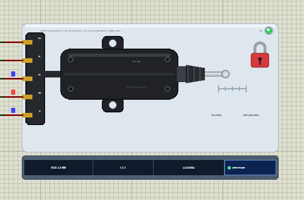
Search door lock in Pick Devices; the device DOORLOCKTEP is in TEPDOORLOCK.LIB (category Electromechanical, Motors) and its model is TEPDOORLOCK.DLL. It is drawn from the side: the black plastic case with its seam and four screws, the two mounting ears above and below, the rod guide, the ribbed rubber boot and the steel rod with an eye at its end for the lock's link. The plug with M+, M-, SL, SU and S is on the left.
At Run the rod moves in and out over a 0 to 20 mm scale. A padlock beside it shows the state: closed and red when the rod is in, open and green when it is out, amber in between. The ON LED lights green while current flows, and the strip under the plate shows the rod's position, the current, the state and the OPEN PANEL button. The plate, the LED, the scale, the padlock, the rating line and the strip are TEP additions; the real actuator has none of them.
The Pins and the Properties
| Pin | What the model does with it |
|---|---|
| M+ | the motor's first wire: 4.0 ohm and 1.5 mH to M-, with its back-EMF |
| M- | the motor's second wire |
| S | the switch's common |
| SL | closed to S within 6 mm of the IN end |
| SU | closed to S within 6 mm of the OUT end |
| Property | Default | What it does |
|---|---|---|
| VOLTAGE | 12 | the rating: 12, or 24 for a truck actuator (the same stroke at twice the voltage) |
| LOAD | DOOR | BENCH (nothing on the rod), DOOR (the lock's linkage and its spring) or JAMMED |
| START | UNLOCKED | the rod at the start: UNLOCKED (out) or LOCKED (in) |
Download Car Door Lock Actuator Library for Proteus
Click the button below to download Car-Door-Lock-Actuator-Library-for-Proteus-v1.0.zip (about 1.2 MB, without the source code of the models):
Car Door Lock Actuator Library for Proteus V1.0- README.txt: installation, the demo, the wiring, the properties, real hardware, troubleshooting and the limits.
- Proteus Library Files:
TEPDOORLOCK.LIBandArduinoV4TEP.LIBfrom our Arduino Library for Proteus V4.0. - Proteus Model Files:
TEPDOORLOCK.DLLandTEPARDUINO.DLL. - Proteus Simulation:
Car-Door-Lock-Actuator-Relay-ArduinoUnoV4.pdsprj,Lock_Demo.hexand copies of the DLLs. - Arduino Code:
Lock_Demo.ino(no library needed).
Good to know: the demo's relays are our Relay Module, a separate library that is not in this zip. Download it from its own article, the Relay Module Library for Proteus, and install TEPRELAY.LIB and TEPRELAY.DLL the same way.
No Proteus yet? Read How to Download and Install Proteus 7 and 8. New to libraries? Follow How to Install a New Library in Proteus.
How to Install Car Door Lock Actuator Library for Proteus
- Close Proteus and extract the whole zip file, for example to your Desktop.
- Copy
TEPDOORLOCK.LIBandArduinoV4TEP.LIBfrom Proteus Library Files into the LIBRARY folder of Proteus (usuallyC:\Program Files (x86)\Labcenter Electronics\Proteus 8 Professional\LIBRARY). - Copy
TEPDOORLOCK.DLLandTEPARDUINO.DLLfrom Proteus Model Files into the MODELS folder. The two Arduino files are the ones of our Arduino Library V4.0; if you have it, they are the same. - Install the Relay Module library the same way if you do not have it yet.
- Delete
TEPDOORLOCK.IDXfrom the LIBRARY folder if it is there. - Start Proteus, press P and search for door lock.
Tip: keep the Proteus Simulation folder together, because the project needs its .hex file and the DLLs beside it. The library is tested in Proteus 8.5; Proteus 7 is not supported.
The Demo Circuit
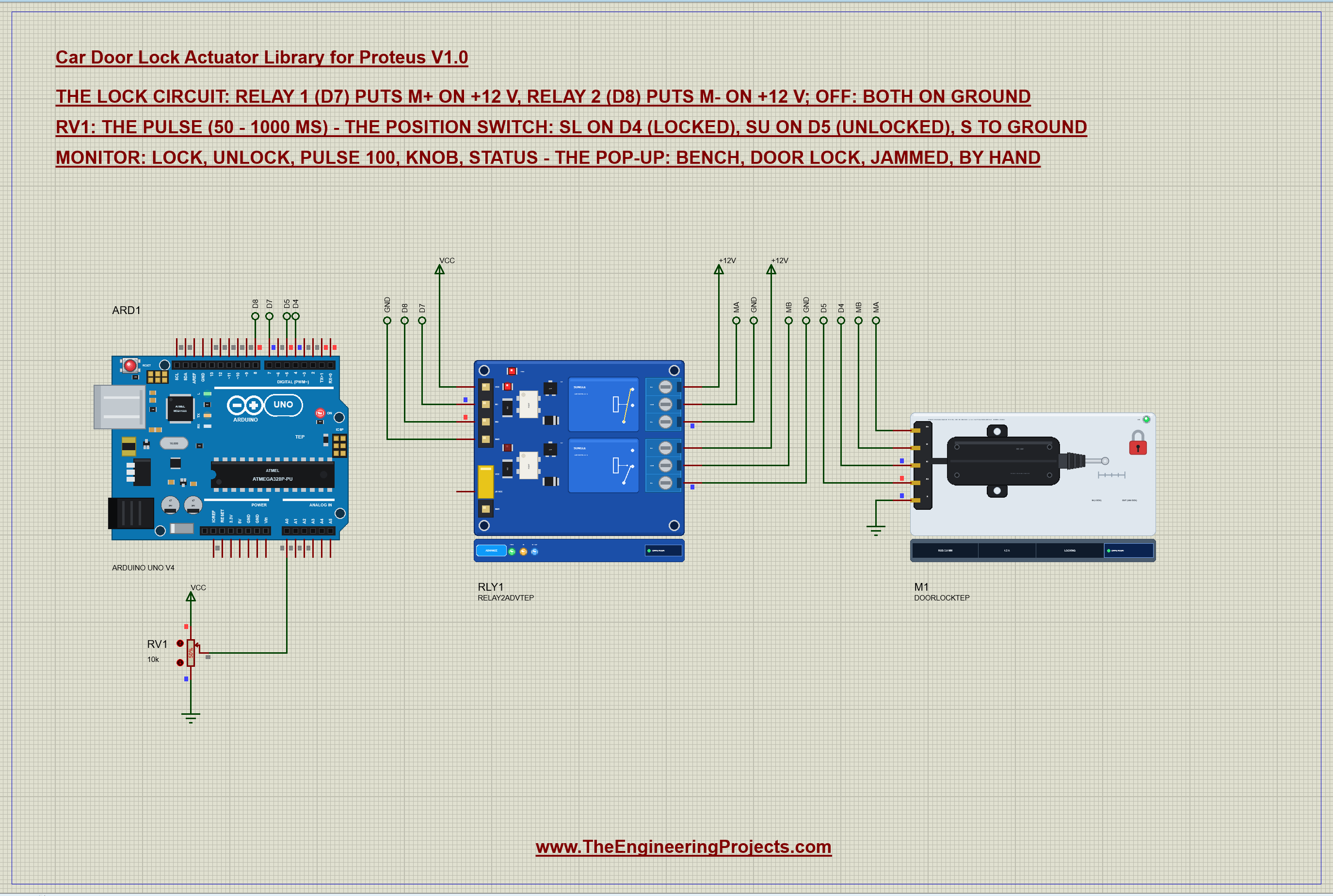
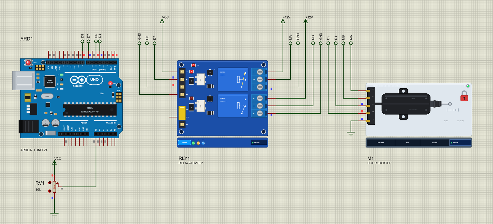
Open Car-Door-Lock-Actuator-Relay-ArduinoUnoV4.pdsprj. ARD1 is an Arduino UNO V4.0 from our Arduino UNO Library for Proteus V4.0, running Lock_Demo.hex with its serial monitor built in. RLY1 is our 2-channel relay module in its pop-up version (RELAY2ADVTEP). M1 is the actuator on the door lock with its rod out, and RV1 is a 10k pot on A0 that sets the length of the pulse, from 50 to 1000 ms. The connections are net labels:
| Part | Pin | Goes to |
|---|---|---|
| Relay module | IN1, IN2 | D7, D8 (active LOW: LOW = the relay on) |
| Relay module | VCC, GND | 5 V, ground |
| Relay 1 | COM1, NO1, NC1 | MA, +12V, GND |
| Relay 2 | COM2, NO2, NC2 | MB, +12V, GND |
| Actuator | M+, M- | MA, MB |
| Actuator | SL, SU, S | D4, D5, ground |
| RV1 | wiper | A0 |
The Central-Locking Circuit
Reversing a motor normally needs an H-bridge. Central locking does it with two ordinary changeover relays, one for each motor wire. At rest, both relays connect their wire to ground through the NC contact. Switching one relay moves its wire to +12 V through the NO contact, while the other wire stays on ground:
| Relay 1 (D7) | Relay 2 (D8) | M+ | M- | The actuator |
|---|---|---|---|---|
| off | off | ground | ground | stopped - the motor is shorted, so it brakes |
| on | off | +12 V | ground | LOCK: the rod pulls in |
| off | on | ground | +12 V | UNLOCK: the rod pushes out |
| on | on | +12 V | +12 V | nothing - the sketch never does this |
The rest position is safe by design: with both relays off the motor's wires are tied together, so it cannot move and a spinning motor is braked. Even both relays on cannot short the supply - it only puts +12 V on both wires.
The Arduino Code
The sketch needs no library. New to Arduino? Start with Arduino Tutorial for Beginners and Introduction to Arduino UNO. The pins come first - two relay inputs and the two switch contacts:
const byte RELAY_LOCK = 7, RELAY_UNLOCK = 8;   // the relay module's IN1 / IN2: LOW = the relay on
const byte SW_LOCKED = 4, SW_UNLOCKED = 5;     // the position switch: LOW = closed (S on ground)
const byte KNOB = A0;
The relay module's inputs are active LOW, so one small function hides the inversion:
void relays(bool lockOn, bool unlockOn) {
  digitalWrite(RELAY_LOCK, lockOn ? LOW : HIGH);
  digitalWrite(RELAY_UNLOCK, unlockOn ? LOW : HIGH);
}
In setup() the relay outputs are set HIGH before the pins become outputs, so the actuator gets no pulse at power-up. The switch inputs use the UNO's pull-ups, because S goes to ground:
  digitalWrite(RELAY_LOCK, HIGH); digitalWrite(RELAY_UNLOCK, HIGH);   // both relays off before the pins drive (no pulse at power-up)
  pinMode(RELAY_LOCK, OUTPUT); pinMode(RELAY_UNLOCK, OUTPUT);
  pinMode(SW_LOCKED, INPUT_PULLUP); pinMode(SW_UNLOCKED, INPUT_PULLUP);
Reading the switch is one function: 1 for locked, 2 for unlocked, 0 for somewhere between:
byte position() {
  if (digitalRead(SW_LOCKED) == LOW) return 1;
  if (digitalRead(SW_UNLOCKED) == LOW) return 2;
  return 0;
}
The Pulse
The pulse comes from RV1, 50 ms with the knob at zero and 1000 ms at the top, unless a fixed pulse was typed:
unsigned int pulseMs() { return fixedPulse ? fixedPulse : 50 + (unsigned long)analogRead(KNOB) * 950UL / 1023; }A pulse switches one relay on and notes when it must end - the sketch never blocks with delay():
void start(byte to) {                         // never both relays: one wire on +12 V, the other on ground
  const unsigned int ms = pulseMs();
  relays(to == 1, to == 2);
  pulseEnd = millis() + ms; moving = true; target = to; checkAt = 0;
When the time is up, both relays go off and a check is planned 0.1 s later:
if (moving && (long)(millis() - pulseEnd) >= 0) { relays(false, false); moving = false; checkAt = millis() + 100; }The check is where the 5-wire actuator pays off. The sketch does not just hope the lock moved - it asks the switch:
    if (lastPos == target) { Serial.print(F("Done - ")); printPosition(lastPos); }
    else { Serial.print(F("NOT done - the rod ")); printPosition(lastPos); Serial.println(F("Jammed, or the pulse too short?")); }
And when the switch changes with no pulse at all, someone used the key or the knob:
if (p != 0 && p != lastPos) { lastPos = p; Serial.print(F("Moved by hand - ")); printPosition(p); }A fixed pulse can be typed for tests, from 50 to 3000 ms:
fixedPulse = constrain(atoi(s + 6), 50, 3000);The HEX file is in the package. To change the sketch, open it in the Arduino IDE and export the compiled binary, as in How to get the HEX file from Arduino. It needs 5,008 bytes of flash (16 % of the UNO) and 269 bytes of RAM.
Running the Demo
Press Run. The UNO's serial monitor, the actuator's pop-up and the relay module's pop-up open over the schematic; move them aside. The rod is out, and the sketch reads the switch at once:
Car Door Lock Actuator demo - The Engineering Projects
Relay 1 (D7): M+ to +12 V = lock. Relay 2 (D8): M- to +12 V = unlock. Switch: SL D4, SU D5. RV1: the pulse.
Commands: lock | unlock | pulse 100 | knob | status | help
The rod: UNLOCKED (SU closed)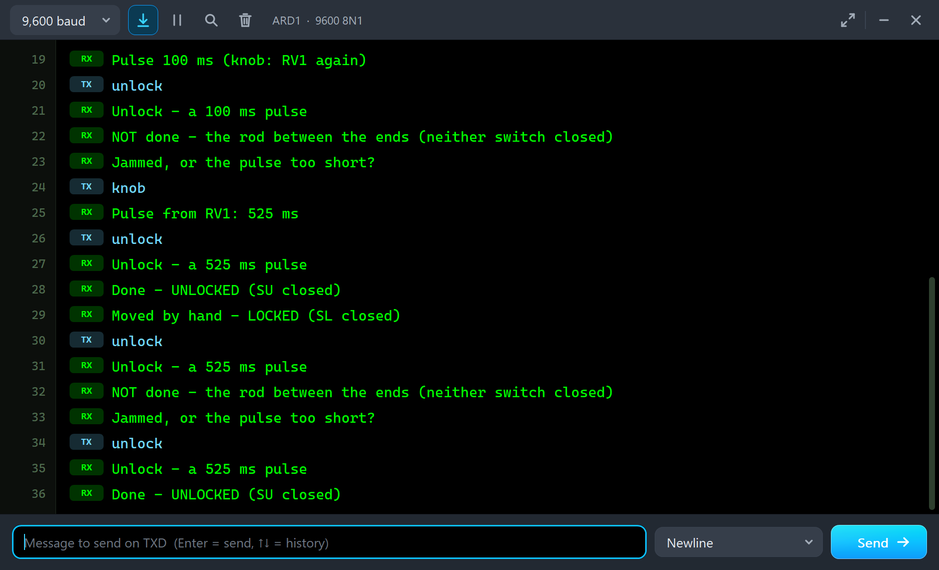
A Lock Pulse
To catch the actuator in the middle of its stroke, start with a long pulse, then lock:
pulse 1000
Pulse 1000 ms (knob: RV1 again)
lock
Lock - a 1000 ms pulse
Done - LOCKED (SL closed)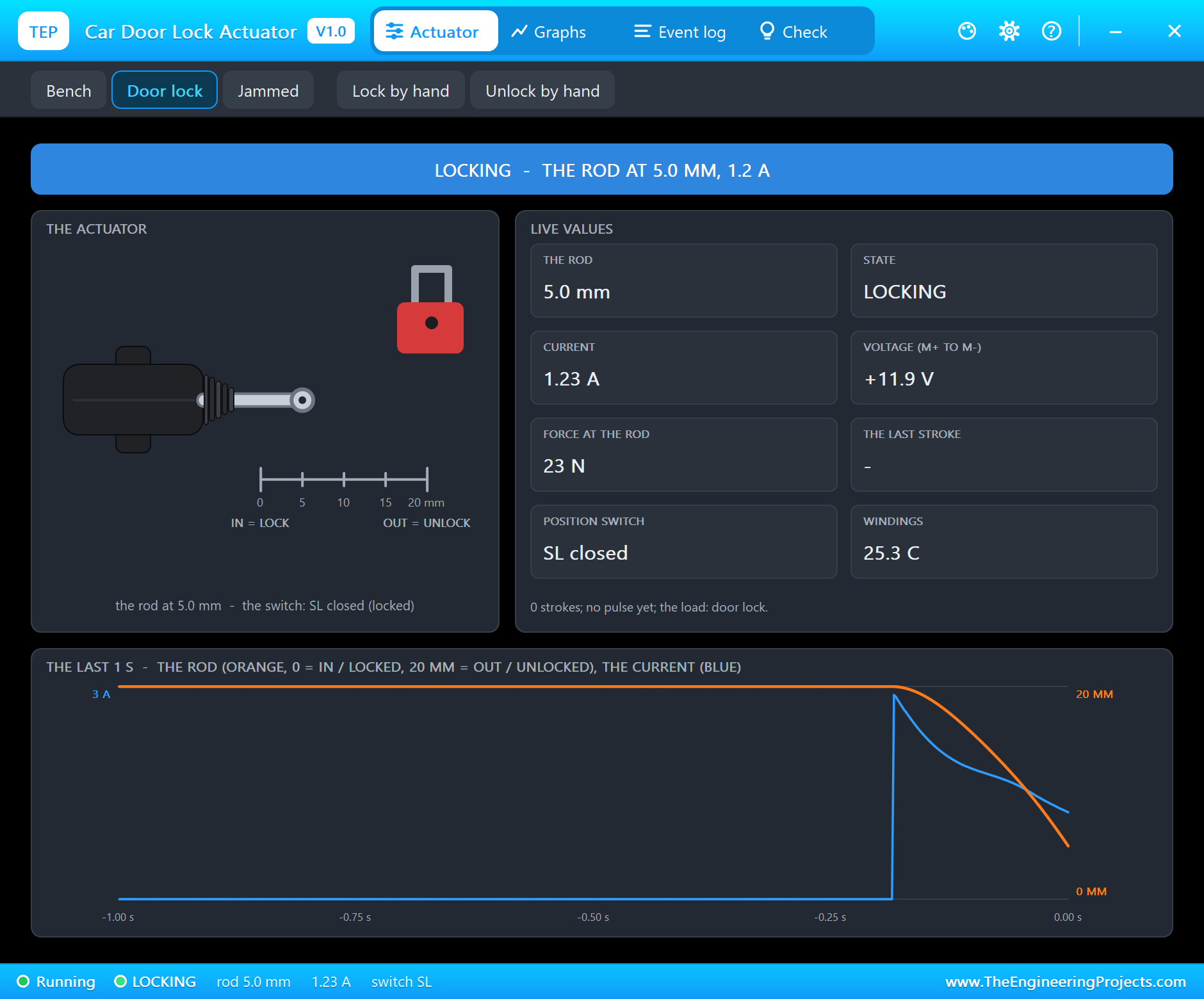
Relay 1 clicks, M+ goes to +12 V and the rod starts to move in. The picture was taken with the simulation paused during the stroke: "LOCKING - THE ROD AT 5.0 MM, 1.2 A", +11.9 V across the motor and 23 N on the rod. The pop-up has the look of our TEP Serial Monitor Advance for Proteus and four tabs: Actuator, Graphs, Event log and Check. The Actuator page shows the state in big letters, the actuator with its rod over the scale and the padlock, and eight live values: the rod, the state, the current, the voltage from M+ to M-, the force at the rod, the last stroke, the position switch and the windings.
The graph at the bottom shows the last second: the rod in orange, the current in blue. The current jumps to about 3 A the moment the relay closes - the motor is still at rest and has no back-EMF - and falls as the motor speeds up. The rod follows a smooth curve down towards zero.
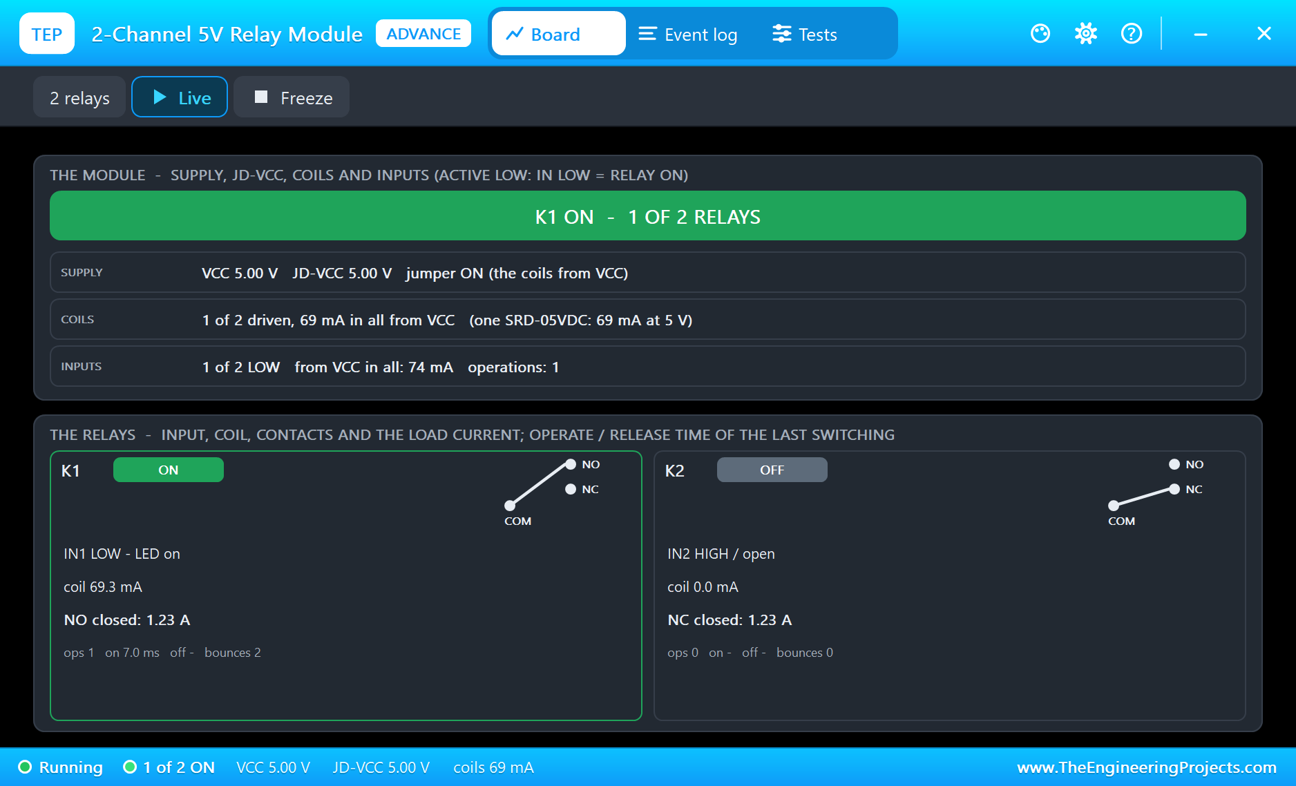
The relay module's pop-up shows the circuit from the other side: "K1 ON - 1 OF 2 RELAYS", coil 69.3 mA, and "NO closed: 1.23 A". K2 is off, and its NC contact carries the same current back to ground - the two relays together form the H-bridge. The log then has the stroke: "LOCKED - the rod in after 0.22 s (20.0 mm, 1.8 A on the way)". But the pulse was a whole second, so the rest of it is spent at the stop: "PULSE 1.00 s to LOCK - 0.77 s of it stalled at the stop, 2.9 A".
An Unlock Pulse From the Knob
Now hand the pulse back to RV1 and unlock:
knob
Pulse from RV1: 525 ms
unlock
Unlock - a 525 ms pulse
Done - UNLOCKED (SU closed)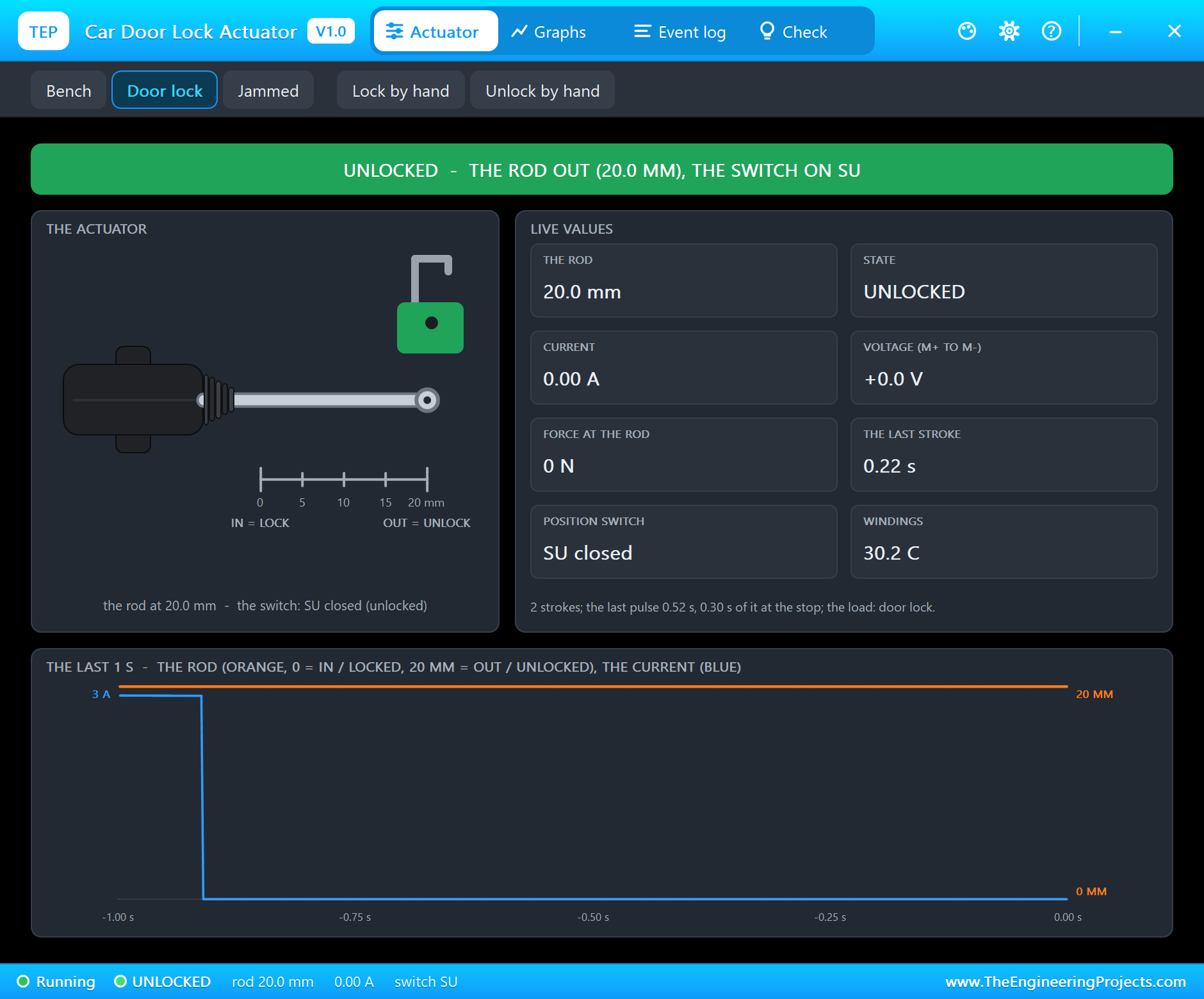
With RV1 at 50 % the pulse is 525 ms - a typical central-locking pulse. The log has "UNLOCKED - the rod out after 0.22 s (20.0 mm, 1.7 A on the way)" and "PULSE 0.52 s to UNLOCK - 0.30 s of it stalled at the stop, 2.9 A". So even a normal pulse spends more than half its time with the motor stalled. That is fine for a fraction of a second; it is the reason the pulse must end. The sketch checks the switch 0.1 s later and prints "Done - UNLOCKED (SU closed)". Typing lock again gives "LOCKED - the rod in after 0.23 s".
A Pulse That Is Too Short
What if the controller's pulse is too short - a faulty module, or a sketch with the wrong number? Try it with the rod in:
pulse 100
Pulse 100 ms (knob: RV1 again)
unlock
Unlock - a 100 ms pulse
NOT done - the rod between the ends (neither switch closed)
Jammed, or the pulse too short?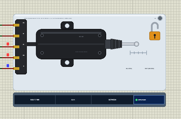
In 100 ms the rod only gets part of the way. The log waits until the rod has come to rest and then warns: "STOPPED MID-STROKE at 7.7 mm - the pulse (0.10 s) ended first: give it 0.3 s or more". The rod stays there - the lock's spring and the friction hold it. Neither switch contact is closed, so the sketch knows something is wrong.
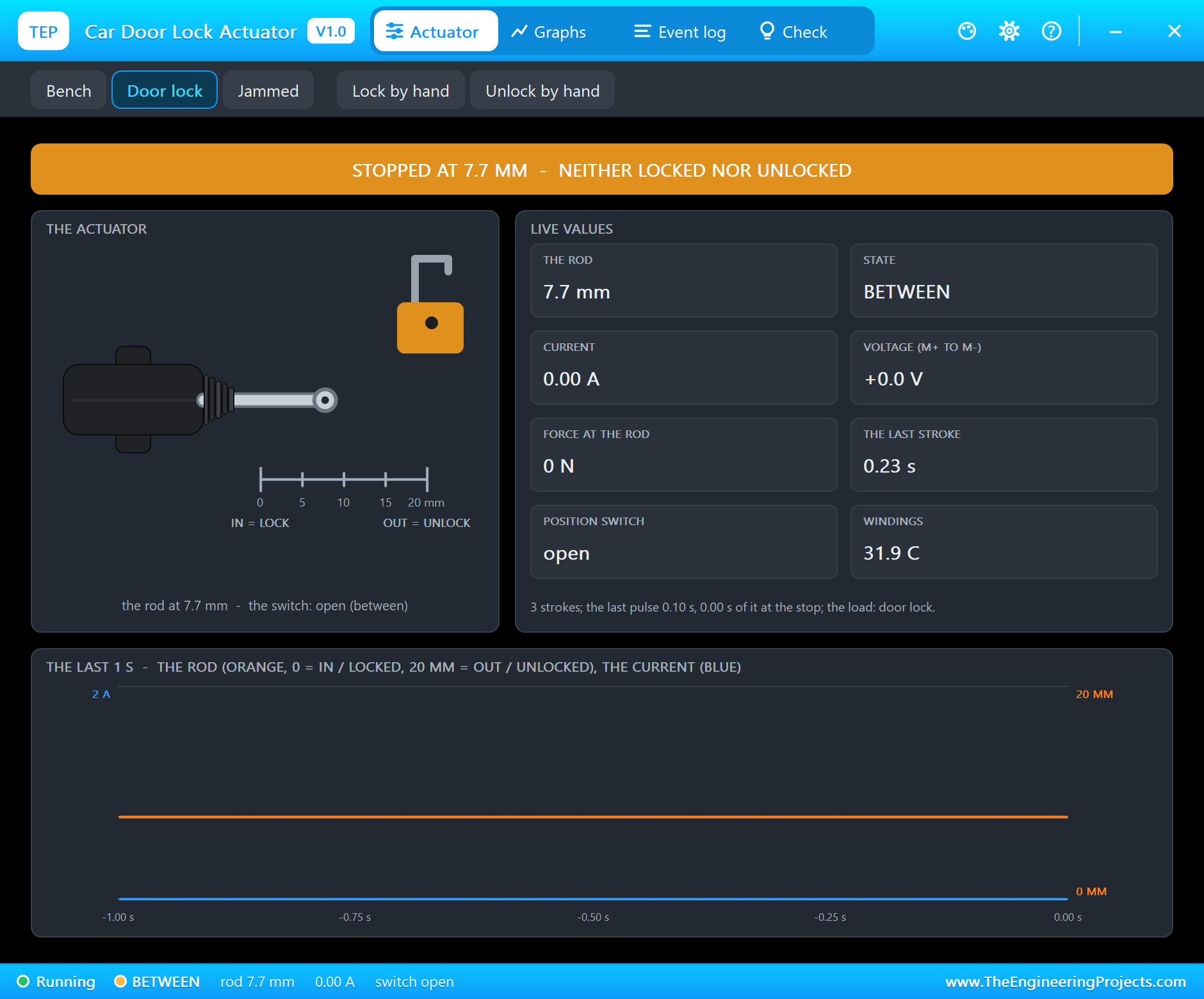
This is a real problem in cars: a door that is neither locked nor unlocked can be opened from outside while the dashboard shows it locked. The pop-up says "STOPPED AT 7.7 MM - NEITHER LOCKED NOR UNLOCKED", and the Check page would mark the pulse in red.
By Hand: the Key and the Knob
The actuator's gears are not self-locking, and a clutch lets the rod move without turning the motor - so the key in the door or the knob inside still work when the battery is flat. Give the knob's pulse back, unlock fully, then click Lock by hand on the pop-up:
knob
Pulse from RV1: 525 ms
unlock
Unlock - a 525 ms pulse
Done - UNLOCKED (SU closed)
Moved by hand - LOCKED (SL closed)
The full unlock starts from 7.7 mm: "UNLOCKED - the rod out after 0.16 s (12.3 mm, 1.9 A on the way)". Then the chip pushes the rod in as a hand would, with no current at all. The log writes "MOVED BY HAND - LOCKED with the key or the knob (the switch: SL closed)", and the sketch, which never sent a pulse, sees the switch change: "Moved by hand - LOCKED (SL closed)". In a car, this is the moment the master door tells the other doors to lock too.
A Jammed Lock
Locks freeze in winter and bend in accidents. Click Jammed on the pop-up - the log notes "LOAD jammed - the lock blocked half-way (10 mm)" - and try to unlock:
unlock
Unlock - a 525 ms pulse
NOT done - the rod between the ends (neither switch closed)
Jammed, or the pulse too short?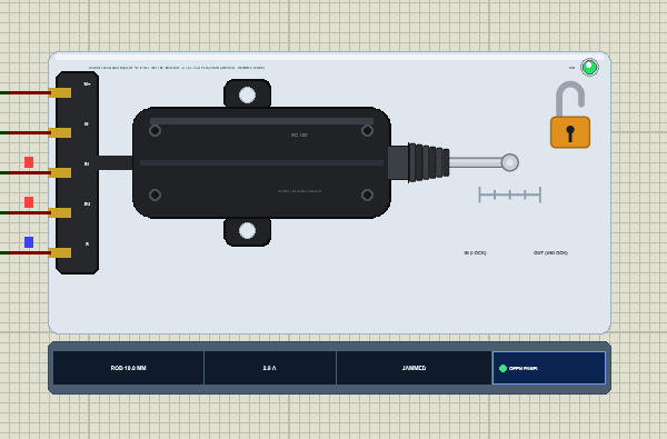
The rod starts out and stops dead at 10 mm. The motor is stalled again, but this time not at the end of its travel: "JAMMED at 10.0 mm - 2.8 A and the rod does not move (a frozen or blocked lock?)". The pop-up turns red, and the force card shows what the motor puts into the jammed lock: 53 N.
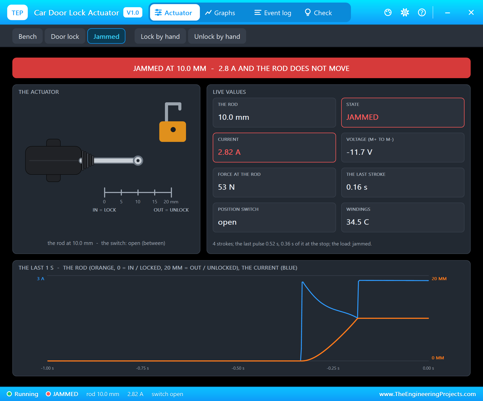
The voltage is -11.7 V because this is an unlock, with M- positive. The trace shows the whole story of the pulse: the current's jump at the start, the rod moving out, and the moment it stops, when the current climbs to the stall value and stays there.
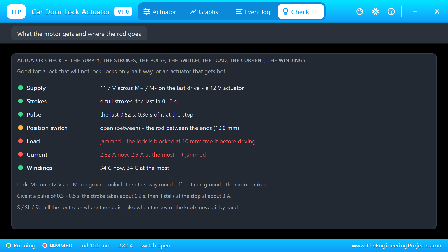
The Check page goes through the supply, the strokes, the pulse, the position switch, the load, the current and the windings, each with a coloured dot. Here the Load row says "jammed - the lock is blocked at 10 mm: free it before driving" and the Current row "2.82 A now, 2.9 A at the most - it jammed". The pulse ends after 525 ms, so the stall is short; the sketch reports "NOT done". Click Door lock to free the lock and unlock again: "UNLOCKED - the rod out after 0.13 s (10.0 mm, 1.9 A on the way)".
Graphs and the Log
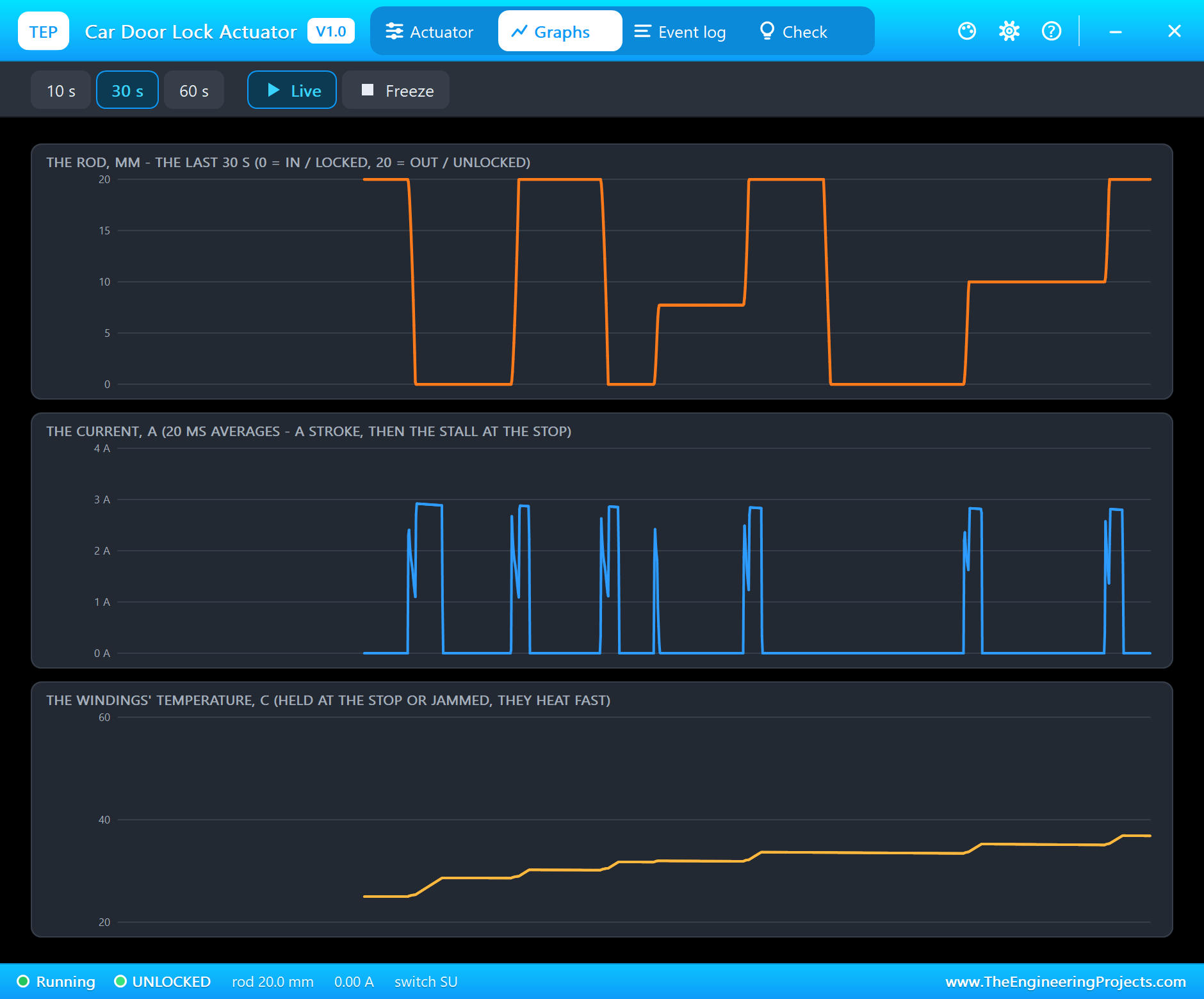
Graphs draws the rod, the current and the windings' temperature over the last 10, 30 or 60 seconds. The 30 s view holds the whole demo: the rod steps between 0 and 20 mm, stops at 7.7 after the short pulse, drops to 0 by hand with no current at all, and stops at 10 when jammed. Every full stroke is a block of current that ends at about 3 A - the stall at the stop; the short pulse is only a spike. The windings warm a little with each pulse.
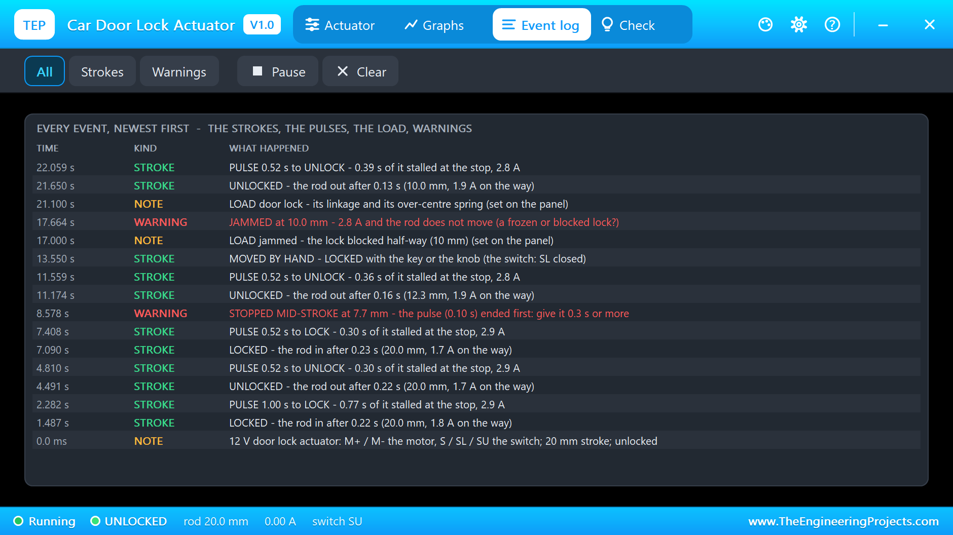
The Event log keeps every stroke with its time and current, every pulse with the time spent at the stop, the hand moves, the load changes and the warnings. Filter it to Strokes or Warnings, pause it, or clear it. One more warning you may meet: HELD AT THE STOP, when a pulse keeps the motor stalled for more than 1.5 s, and HOT if the windings pass 100 C.
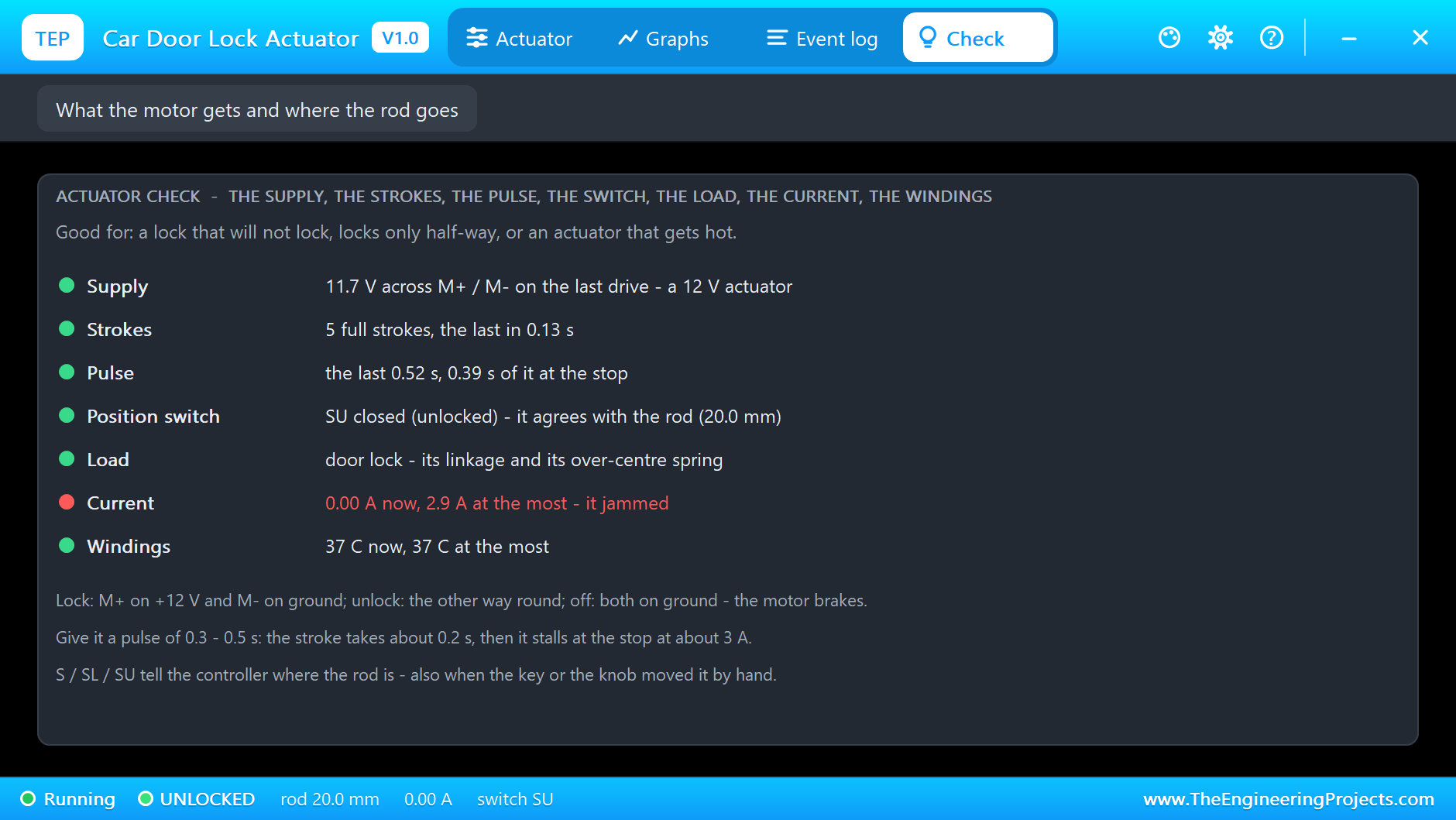
At the end of the run the Check page sums it up: 11.7 V across M+ / M- on the last drive, 5 full strokes, the last pulse 0.52 s with 0.39 s of it at the stop, SU closed and agreeing with the rod, the Current row still red because of the jam, and the windings at 37 C.
How the Model Works
The motor sits between M+ and M- as 4.0 ohm and 1.5 mH in series with its back-EMF. At every analog step the model puts a conductance and a current source into the circuit for it, so the relays, the supply and the motor are solved together. The position switch is two contacts that close near each end. The step is held to 0.5 ms while the rod moves or current flows, and 5 ms at rest.
Between the analog points the mechanics run in sub-steps of at most 50 us. The motor's torque drives the rod through gears and a rack that move it 0.15 mm for every radian of the motor, 35 % efficient. Against it work the motor's own friction and the load: 2 N on the bench; on the door lock 10 N of friction and an over-centre spring of 12 N that pushes the rod towards the nearer end, which is what holds a car lock firmly locked or unlocked. At 0 and 20 mm the rod stops dead and the motor stalls. The windings warm with the current and cool to the air.
We checked the model on a PC with 13 automatic tests: a 0.45 s lock pulse on the door lock makes the stroke in 0.222 s with 2.91 A at the stop; the bench is faster, 0.181 s; a 110 ms pulse leaves the rod at 10.37 mm, where it stays; the jam stops it at 10.0 mm; a pulse held on gives HELD AT THE STOP, and a minute at the stop heats the windings to 190 C; and a 24 V actuator on 24 V strokes in 0.219 s. The demo project is read back from disk with 90 checks.
Troubleshooting
- It does not move and nothing is logged: no supply on M+ or M-, or the relays are not driven.
- STOPPED MID-STROKE: the pulse is too short - give it 0.3 s or more.
- JAMMED: the Jammed load is chosen - click Door lock.
- HELD AT THE STOP or HOT: the power stays on after the stroke - use a pulse.
- The sketch says "NOT done": the rod did not reach the end; check SL on D4, SU on D5 and S on ground.
- The actuator is not simulated:
TEPDOORLOCK.DLLis missing from MODELS and from the project folder. - No relay module: install our Relay Module library (
TEPRELAY.LIBandTEPRELAY.DLL). - No UNO or no monitor:
TEPARDUINO.DLLis missing; a closed monitor opens again with a click on the UNO's USB port. - No pop-up: click OPEN PANEL on the actuator's strip, or turn "Open the panel at Run" on in its Settings.
Things to Know Before Wiring a Real Door Lock Actuator
- It draws more than it looks: about 1.5 to 2 A on the way and about 3 A stalled at the stop, more for the "heavy duty" types. Use relays (the two-relay circuit above) or an H-bridge, and a fuse - never an Arduino pin.
- Always use a pulse: 0.3 to 0.5 s, then cut the power. Held at the stop, the actuator heats and burns out.
- Read the switch: with a 5-wire actuator, SL and SU tell you whether it really locked; a frozen lock stops it half-way.
- Mind the direction: which way locks depends on how the actuator is mounted - swap M+ and M- if it works the wrong way round.
- Leave room for the hand: the key and the knob move the rod through the clutch - your sketch should expect the lock to change by itself.
Limitations of the Simulation
- Not modelled: the car's lock module and its alarm, vacuum (pneumatic) locks, the rubber boot's drag, the clutch's own feel and the motor's wear.
- The plate, the ON LED, the scale, the padlock, the rating line and the strip are TEP additions.
- The model is our own, written from the typical data of 12 V car door lock actuators; this library is not made or endorsed by any car or lock maker, Arduino or Labcenter.
- Licences: the demo HEX contains the Arduino AVR core 1.8.6 (LGPL); the sketch is included and the README gives the source link. The relay module of the demo is our separate library.
- Tested in Proteus 8.5 in October 2026 with the demo as shipped: lock, unlock, a short pulse, by hand, jammed, freed, and all four pages of the pop-up. Proteus 7 is not supported.
So, that was all about the Car Door Lock Actuator Library for Proteus V1.0. I hope it helps you with your cabinet lock, your prop or your central-locking project - and that you never hold an actuator at its stop again. If you have any questions, ask in the comments and I will help you out. Till the next tutorial, take care and have fun!

Comments
0