


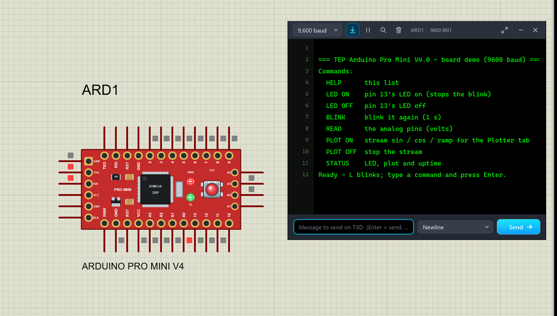
Arduino Pro Mini Library for Proteus V4.0 (Working LEDs + Monitor)


Hello friends, I hope you all are doing great. Today, I am going to share the new Arduino Pro Mini Library for Proteus V4.0. The Arduino Pro Mini is the tiny red board from SparkFun: an ATmega328P, a resonator, a voltage regulator and a reset button on a board of 0.7 x 1.3 inches, with no USB connector at all. You program it through a six-pin FTDI header on one end. With this Arduino Pro Mini Library for Proteus, you place the board on your sheet, load the HEX file of your sketch and press Run: the PWR LED lights, the 13 LED follows pin 13, the RESET button works with the bootloader, and a serial monitor built into the board shows everything your sketch prints.
Version 4.0 is the newest of our Arduino libraries for Proteus; the first one came out in 2015. The Pro Mini is one of six boards in the TEP Arduino Library V4.0: one library file and one model file hold the UNO, the Mega 2560, the Mega 1280, the Nano, the Pro Mini and the Mini. This post is all about the Pro Mini; our Arduino Library for Proteus V4.0 shows all six boards side by side.
NOTICE: The Arduino boards are the heart of almost every Proteus library our team makes, so V4.0 is very special to us. We drew every board again from the real one and gave it LEDs that really work, a working RESET button and a serial monitor of its own, while keeping V3.0's pin order. It took our team a lot of hard work and many test runs in Proteus. Your feedback is the fuel that keeps us going, so please tell us what you think in the comments below or in the Arduino Proteus Library board of our forum. And if our free libraries help you, you can buy us a coffee. So, let's get started with the Arduino Pro Mini Library for Proteus V4.0:
What is the Arduino Pro Mini?
The Arduino Pro Mini was designed by SparkFun Electronics as a minimal Arduino for projects that stay put. Once the sketch is uploaded, such a project needs no USB connection, so the USB-to-serial chip was left off the board. What remains is the ATmega328P with its 16 MHz resonator, a small voltage regulator, two LEDs and a reset button, on a thin red board with a row of 12 pads along each long edge.
To upload a sketch, you plug a USB-to-serial adapter (an FTDI breakout board or an FTDI cable) into the six pads on one end. They are labelled GRN, TXO, RXI, VCC, GND and BLK. BLK and GRN are named after the black and the green wire of the FTDI cable, so you can plug it in the right way round. GRN carries the adapter's DTR signal. On the board, it goes through a 0.1 uF capacitor to the reset pin: when the Arduino IDE opens the port, DTR falls, the capacitor turns that edge into a short reset pulse, and the bootloader is ready for the upload. This is called auto-reset, and it saves you from pressing the reset button at the right moment.
The Pro Mini comes in two versions: 5 V at 16 MHz and 3.3 V at 8 MHz. Our Proteus board is the 5 V, 16 MHz version, with the same supply and clock as an Arduino UNO. Without a USB chip, the board is small, light and cheap, which makes it a favourite for battery projects, wearables and anything that has to fit in a small box.
The Arduino Pro Mini at a Glance
| Feature | Value |
|---|---|
| Designer | SparkFun Electronics (open hardware) |
| Microcontroller | ATmega328P (TQFP-32): 32 KB flash (30 KB for your sketch next to the bootloader), 2 KB SRAM, 1 KB EEPROM |
| Version | 5 V at 16 MHz (this library); there is also a 3.3 V, 8 MHz version |
| Digital pins | D0 - D13; PWM on 3, 5, 6, 9, 10 and 11 |
| Analog inputs | A0 - A7 (10-bit); A6 and A7 are analog inputs only |
| Serial port | D0 (RXI) and D1 (TXO), on a pin row and on the FTDI header |
| Programming | Six-pin FTDI header: GRN (DTR), TXO, RXI, VCC, GND, BLK; no USB connector |
| Power | RAW into the on-board regulator (up to 12 V), or a regulated 5 V on VCC |
| LEDs | PWR (red) and 13 (green, on pin 13); no TX / RX LEDs |
| Reset | A reset button and two RST pins; GRN (DTR) resets the chip through a 0.1 uF capacitor |
| Size | 0.7 x 1.3 in (18 x 33 mm) |
What's New in Arduino Pro Mini Library for Proteus V4.0
Our earlier Arduino Library for Proteus V3.0 (2023) already had a Pro Mini. V4.0 keeps what made it useful: the microcontroller is still Proteus's own AVR model, so your sketch, the HEX upload, the clock and fuse properties and Proteus's AVR debug windows work as before. Around that model, V4.0 builds the real board:
- Drawn again as the real board: SparkFun's red Pro Mini as a detailed top view, lying lengthwise, with gold pads, the pin names printed inside the rows, the FTDI header, the regulator, the ATmega328P, the resonator, the two LEDs and the reset button.
- Working LEDs: PWR lights with power, and 13 follows pin 13 the way the real LED does.
- A working RESET button with the bootloader: hold it, and the chip stays in reset; release it, and 13 flashes 3 times before the sketch starts again.
- The FTDI header with DTR auto-reset: six pins on the left end; a falling edge on GRN resets the chip, as on the real board.
- Real supply pins: VCC is a 5 V source you can power other parts from, and all four GND pins are tied to ground.
- A built-in serial monitor on D0 / D1, with Board, Monitor and Plotter tabs: no Virtual Terminal to wire.
- V3.0 bugs fixed: the V3.0 Pro Mini had an AREF pin that the real board does not have (V4.0 has none), its A6 / A7 pins had no electrical type (now they are analog inputs), and the "Clock Frequence" property is now spelled "Clock Frequency".
The pins that V3.0 had keep their names and come first, in V3.0's order, but their positions on the sheet have changed with the new drawing. So a V3.0 design does not swap pin for pin: place the V4.0 board and wire it again. V3.0 and V4.0 can stay installed side by side, because their files and device names differ.
Download Arduino Pro Mini Library for Proteus V4.0
Click the button below to download Arduino-Pro-Mini-Library-for-Proteus-v4.0.zip (about 0.91 MB, without the C++ source code):
Arduino Pro Mini Library for Proteus V4.0- README.txt: a detailed guide to the board, the built-in monitor, the properties, the demo, real hardware and the test results.
- Proteus Library Files:
ArduinoV4TEP.LIB, the TEP Arduino Library V4.0 with all six boards. - Proteus Model Files:
TEPARDUINO.DLL, the board model with the built-in serial monitor. - Proteus Simulation:
PROMINI-V4-Board-Demo.pdsprj, its sketchTEP_Board_Demo_PROMINI.hexand a copy of the DLL, so the demo runs as it is. - Arduino Code:
TEP_Board_Demo.ino, the demo sketch; it needs no extra Arduino library.
The library and the model in this zip are the same for all six boards; only the demo is the Pro Mini's. The C++ source code of the model is not included.
How to Install Arduino Pro Mini Library for Proteus V4.0
- Close Proteus and extract the whole zip file to a normal folder, for example your Desktop.
- Copy
ArduinoV4TEP.LIBfrom Proteus Library Files into the LIBRARY folder of Proteus, usuallyC:\Program Files (x86)\Labcenter Electronics\Proteus 8 Professional\LIBRARY(on some PCsC:\ProgramData\Labcenter Electronics\Proteus 8 Professional\LIBRARY; use the folder that already holds Proteus's own .LIB files). - Copy
TEPARDUINO.DLLfrom Proteus Model Files into the MODELS folder (...\Proteus 8 Professional\MODELS). - If an
ArduinoV4TEP.IDXfile is in the LIBRARY folder, delete it. - Start Proteus, press P (Pick Devices) and search for V4.0 or Arduino. The six boards are in the category Arduino > Arduino Boards; pick ARDUINO PRO MINI V4.0.
Note: Tested in Proteus 8.5; Proteus 7 is not supported. Do you already have our V3.0 Arduino library? Keep it: V3.0 and V4.0 use other file and device names, so both can stay installed.
The Arduino Pro Mini in Proteus
Here is ARD1, the Pro Mini of the demo, while the simulation runs (the monitor window is left out of this picture):
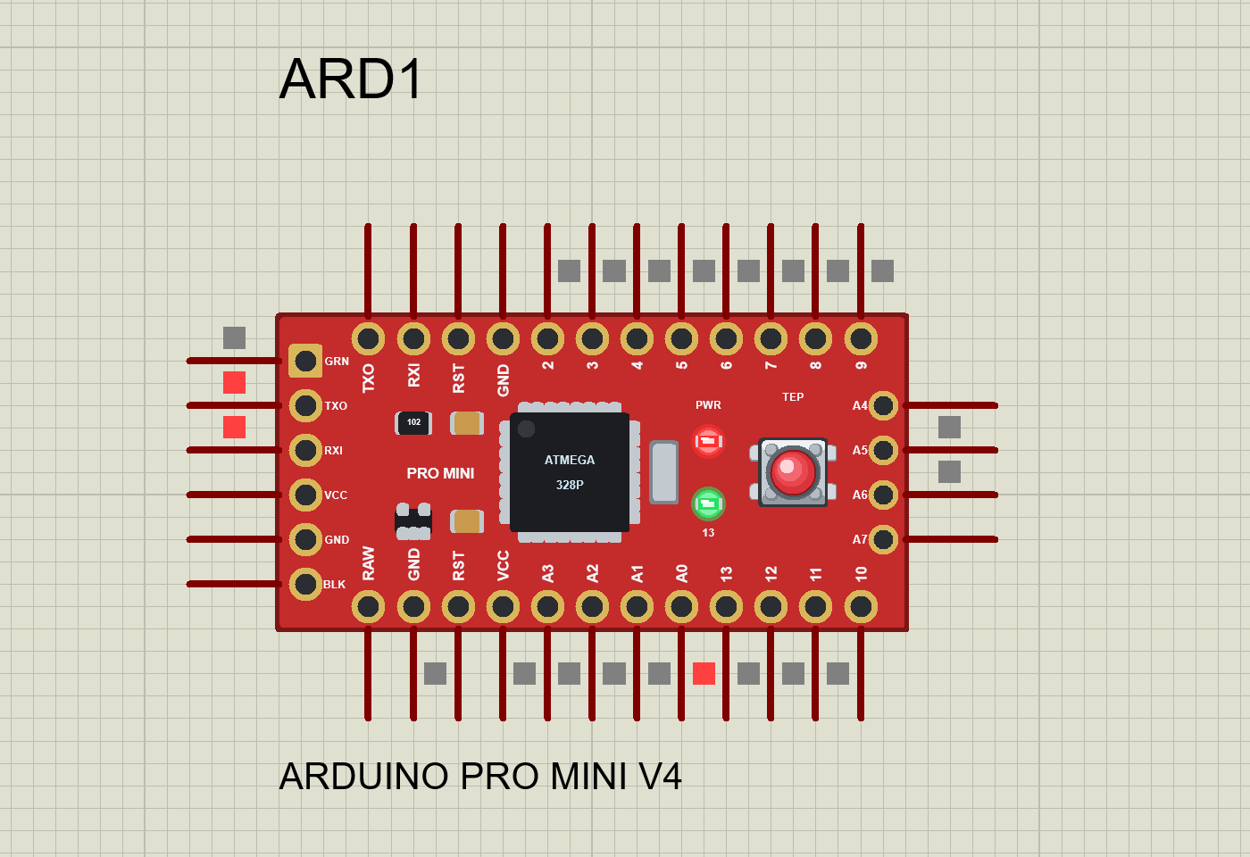
We drew SparkFun's red Pro Mini as a clean top view in its real colour, lying lengthwise: the two rows of gold pads with the pin names printed inside, the six FTDI pads on the left end (the first one, GRN, square), the voltage regulator, two capacitors and a "102" resistor, the PRO MINI print, the ATmega328P in its TQFP-32 package, the silver resonator, the PWR and 13 LEDs, and the reset button. The real board is 1.3 inches long; ours is drawn 1.4 x 0.7 inches, because the FTDI pads and the A4 - A7 pins need their own columns on a Proteus symbol. The board's closest relative in the library is the Arduino Mini, drawn at the same size, with its programming pads on the left end, too; see our Arduino Mini Library for Proteus V4.0.
The small coloured squares next to the pins are not part of our board: they are Proteus's own logic-state markers. Red means HIGH; in the picture, pin 13 (its LED is on) and the idle serial lines TXO and RXI on the FTDI header are red. If you do not like them, switch them off in System > Set Animation Options (Show Logic State of Pins).
Pinout of the Arduino Pro Mini V4.0
The board has 34 pins, with the names printed on the real board:
| Where | Pins, left to right (top to bottom on the ends) | Notes |
|---|---|---|
| Top row, pins point up | TXO, RXI, RST, GND, 2, 3, 4, 5, 6, 7, 8, 9 | The serial port (D1, D0), reset, ground and D2 - D9 |
| Bottom row, pins point down | RAW, GND, RST, VCC, A3, A2, A1, A0, 13, 12, 11, 10 | Supply, reset, A0 - A3 and D10 - D13 |
| Left end, pins point left | GRN, TXO, RXI, VCC, GND, BLK | The FTDI header; GRN is DTR |
| Right end, pins point right | A4, A5, A6, A7 | A4 / A5 are also SDA / SCL; A6 / A7 are analog only |
| Pin | What it does |
|---|---|
| D0 (RXI) / D1 (TXO) | The hardware serial port (Serial); the built-in monitor listens on D1 and talks on D0 |
| D2 / D3 | External interrupts INT0 / INT1 (attachInterrupt()) |
| D3, D5, D6, D9, D10, D11 | PWM outputs (analogWrite()) |
| D10 - D13 | SPI: SS, MOSI, MISO and SCK |
| D13 | Also drives the 13 LED |
| A0 - A5 | Analog inputs, and digital pins as well (D14 - D19) |
| A4 / A5 | I2C: SDA / SCL (the Wire library) |
| A6 / A7 | Analog inputs only: analogRead() works, digitalRead() does not |
| RST (2 pins) | Reset, active LOW |
| GRN | DTR from an FTDI adapter: a falling edge resets the chip |
| VCC (2 pins) | The 5 V supply of the board, a 5 V source in Proteus |
| RAW | The regulator's input on a real board; a load only in Proteus |
| GND, BLK (4 pins) | Ground |
TXO and RXI appear twice, on the top row and on the FTDI header: both TXO pins are D1 and both RXI pins are D0, as on the real board. There is no AREF pin: the real Pro Mini has none, so V4.0 dropped the one V3.0 drew.
The FTDI Header and Auto-Reset
The six pins on the left end point left, the way an FTDI adapter plugs into the real board: GRN (DTR), TXO, RXI, VCC, GND and BLK. In Proteus, they do two jobs:
- Click the header to open the built-in serial monitor. The Pro Mini has no USB socket you could click, so the FTDI header takes that role.
- GRN is DTR. A falling edge on GRN resets the chip, as on the real board, where the 0.1 uF capacitor turns the adapter's DTR edge into a reset pulse. Then the bootloader runs, as after the RESET button.
With MONITOR=YES (the default), the built-in monitor already sits on D0 / D1, like an adapter plugged into the header. If you would rather use a Proteus Virtual Terminal or one of our TEP Serial Monitors on TXO / RXI, set MONITOR=NO, and D0 / D1 are free.
Supply Pins
VCC is a real 5 V source inside the model (0.1 ohm): power your sensors and modules from it, as you would from a real board's regulated 5 V. All four GND pins (the two in the rows, the header's GND and BLK) are tied to ground. RAW is the regulator's input on a real Pro Mini; in Proteus it is only a load (1 Mohm), and the board runs as if it were powered at VCC. The monitor's Board tab shows both: VCC 5.00 V and RAW 0.00 V.
Component Properties
| Property | Meaning | Default |
|---|---|---|
| Upload Hex File | Your sketch: a HEX, ELF or COFF file | The demo: TEP_Board_Demo_PROMINI.hex |
| Clock Frequency | The clock of the AVR model | 16MHz |
| BOOTLOADER | YES: after RESET, 13 flashes 3 times and the sketch starts 1 s later, as on a real board; NO: the sketch starts at once | YES |
| MONITOR | YES: the built-in serial monitor on D0 / D1; NO: D0 / D1 are free for your own terminal | YES |
| BAUD | The monitor's baud rate: 300 to 2000000, or AUTO (it measures the sketch's bits) | 9600 |
| AUTOOPEN | YES: the monitor window opens at Run; NO: click the FTDI header to open it | YES |
The AVR fuses, the EEPROM file and the trace switches are Proteus's own and stay hidden, as in V3.0.
The PWR and 13 LEDs
A real Pro Mini has two LEDs, and so does ours. There are no TX / RX LEDs, because the real board has none; many FTDI adapters carry them instead.
| LED | Colour | When it is lit |
|---|---|---|
| PWR | Red | While the board has power: from the moment you press Run |
| 13 | Green | While D13 drives HIGH; a faint glow while D13 is an INPUT_PULLUP; dark while D13 is LOW or floats (an INPUT, or the chip in reset) |
The 13 LED hangs straight on pin 13 through its resistor, as on the real board, so the model asks the pin itself. A HIGH output lights it fully; INPUT_PULLUP lets only the weak pull-up current through, so it glows faintly; a LOW output or a floating input leaves it dark. This is different from our UNO R3 and Mega 2560, whose L LED sits behind an op-amp buffer and glows dimly while D13 floats.
On the sheet, the LEDs light up in a few steps and fade out over a few frames, so even a short blink is easy to see. That soft glow is a drawing choice of ours, not a feature of the real board. The demo sketch and the monitor call this LED "L", its name on most Arduino boards; on the Pro Mini it is printed "13".
Do you miss the TX / RX LEDs while you watch the serial traffic? The monitor's status bar counts the bytes in both directions: RX for what the board sent, TX for what you sent.
RESET Button and the Bootloader
The reset button near the right end is drawn as a tactile switch, and it works like one. Click and hold it: the cap sinks and darkens, and the chip is held in reset. All its pins float, so the 13 LED goes dark, while PWR stays lit:
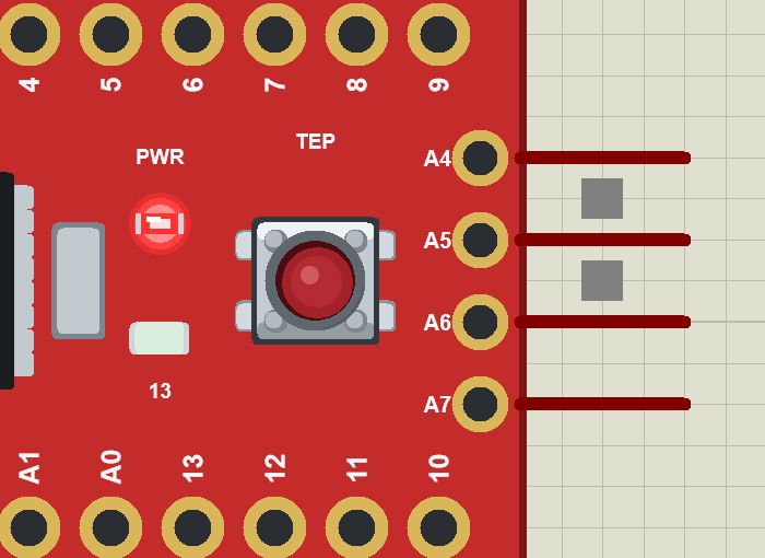
Release it, and the bootloader runs: the 13 LED flashes 3 times (D13 really toggles, in steps of 62.5 ms), and the sketch starts 1 s after the release, so the monitor shows the start-up text again. The RESET key on the monitor's Board tab does the same with a 20 ms press. With BOOTLOADER=NO, the sketch starts at once after the release.
This follows a real Arduino: after a reset, the bootloader waits about a second for an upload before it starts the sketch, while a power-on starts the sketch at once (in Proteus: pressing Run). The 3 flashes are the pattern of optiboot, the bootloader of the UNO and the Nano; the model uses it on every board, so you can always see that the bootloader ran.
Arduino Pro Mini Proteus Simulation: The Demo
Open PROMINI-V4-Board-Demo.pdsprj from the Proteus Simulation folder. Keep TEP_Board_Demo_PROMINI.hex and TEPARDUINO.DLL beside it, so that it runs as it is. The demo is just the board: nothing is wired to it, because its own LEDs and its built-in monitor show everything.
- Press Run. PWR lights, the monitor window opens with the sketch's start-up text, and the 13 LED blinks once a second.
- Type HELP in the monitor and press Enter: the command list comes back. Try READ, LED ON, LED OFF and BLINK.
- Type PLOT ON and open the Plotter tab; PLOT OFF stops the stream.
- Hold the board's RESET button and watch 13 go dark; release it: 13 flashes 3 times, and the start-up text comes again a second later.
- Close the monitor window and click the FTDI header to open it again.
The Start-Up Text
The monitor pictures in this section show its Simple interface: only the text, one slim toolbar (baud rate, follow, pause, search and clear) and the line to send. Press Ctrl+Shift+U (or use the ... menu) to switch to it, and Esc or the expand arrows at its top right to go back to the full interface with its tabs. Right after Run, the board prints:
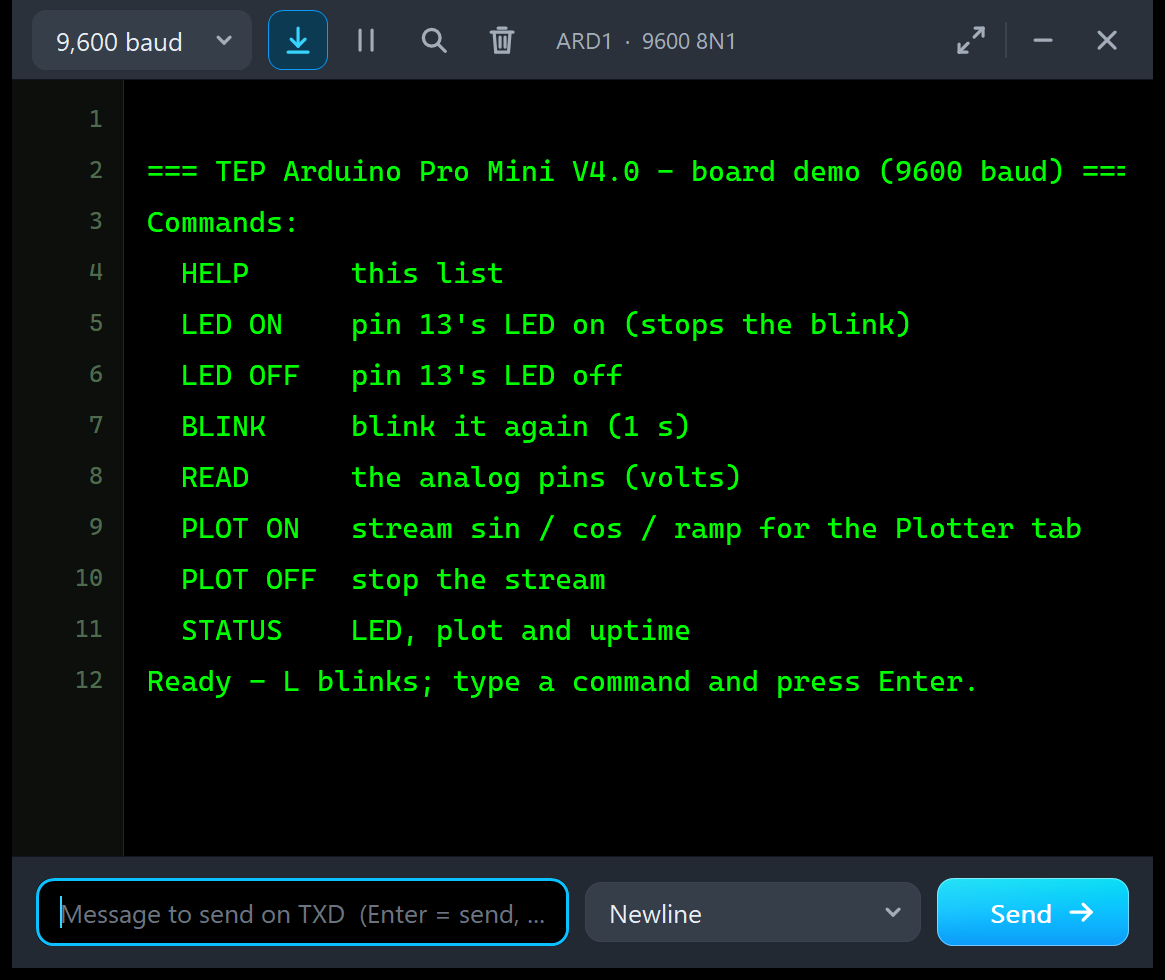
=== TEP Arduino Pro Mini V4.0 - board demo (9600 baud) ===
Commands:
  HELP      this list
  LED ON    pin 13's LED on (stops the blink)
  LED OFF   pin 13's LED off
  BLINK     blink it again (1 s)
  READ      the analog pins (volts)
  PLOT ON   stream sin / cos / ramp for the Plotter tab
  PLOT OFF  stop the stream
  STATUS    LED, plot and uptime
Ready - L blinks; type a command and press Enter.
The banner names the board. The sketch is the same for all six boards; the Arduino IDE tells it which board it is built for:
#elif defined(ARDUINO_AVR_PRO)
const char BOARD[] = "Arduino Pro Mini";
ARDUINO_AVR_PRO is defined when you build for the board "Arduino Pro or Pro Mini". Then setup() prints an empty line (line 1 in the picture), the banner, the command list and the Ready line:
void setup() {
  pinMode(LED_PIN, OUTPUT);
  Serial.begin(9600);
  Serial.println();
  Serial.print(F("=== TEP "));
  Serial.print(BOARD);
  Serial.println(F(" V4.0 - board demo (9600 baud) ==="));
  printHelp();
  Serial.println(F("Ready - L blinks; type a command and press Enter."));
  nextBlinkAt = millis();
}
The F("...") around the fixed texts keeps them in flash memory, instead of the ATmega328P's 2 KB of RAM. The sketch needs no extra library, and it prints nothing on its own after the Ready line: the monitor stays quiet until you type a command or start the plot stream.
The Demo Commands
| Command | What it does | The answer |
|---|---|---|
| HELP | Prints the command list | "Commands:" and eight lines |
| LED ON | Stops the blink and switches the 13 LED on | "L (pin 13) is ON" |
| LED OFF | Stops the blink and switches the 13 LED off | "L (pin 13) is OFF" |
| BLINK | Blinks again: 500 ms on, 500 ms off | "L (pin 13) blinks again" |
| READ | Reads every analog pin, A0 - A7 | One line per pin: the count and the volts |
| PLOT ON | Streams sin / cos / ramp every 200 ms for the Plotter tab | "Plot stream ON - open the Plotter tab" |
| PLOT OFF | Stops the stream | "Plot stream OFF" |
| STATUS | The LED, the plot stream and the uptime | One line: the LED, the plot stream and the uptime in seconds |
Every command is echoed first ("You typed: READ"). The sketch collects the characters of a line until Enter (a carriage return or a newline) ends it. With the monitor's line ending set to "No line ending", a pause of 100 ms ends the line instead:
  while (Serial.available() > 0) {
    char c = Serial.read();
    lastCharAt = millis();
    if (c == '\r' || c == '\n') handleLine();
    else if (lineLength < sizeof(line) - 1) line[lineLength++] = c;
  }
  if (lineLength > 0 && millis() - lastCharAt >= LINE_TIMEOUT_MS) handleLine();   // "No line ending": a pause ends it
Then handleLine() turns the line into upper case and drops extra spaces, so "led on", "Led On" and " LED ON " all work:
  for (byte i = 0; i < lineLength; i++) {
    char c = line[i];
    if (c >= 'a' && c <= 'z') c -= 32;
    if (c == ' ' && (n == 0 || cmd[n - 1] == ' ')) continue;
    cmd[n++] = c;
  }
READ: Every Analog Pin
Type READ and press Enter. In this picture, the monitor has tagged each line: TX for the line you sent, RX for the lines the board sent back.
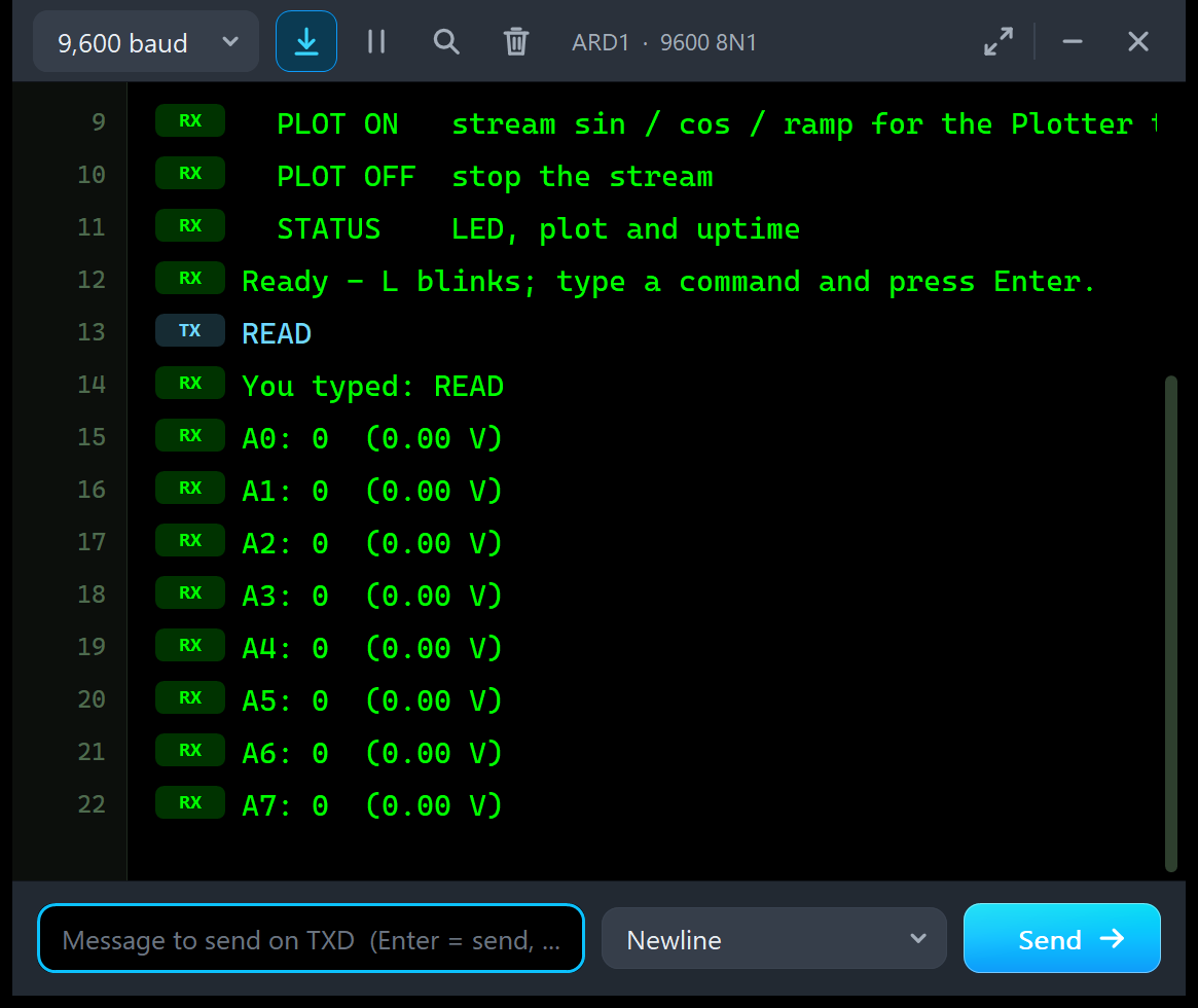
You typed: READ
A0: 0  (0.00 V)
A1: 0  (0.00 V)
A2: 0  (0.00 V)
A3: 0  (0.00 V)
A4: 0  (0.00 V)
A5: 0  (0.00 V)
A6: 0  (0.00 V)
A7: 0  (0.00 V)
The Pro Mini build of the sketch reads eight pins, A0 - A7, while the UNO build reads six: the Arduino core gives the Pro Mini eight analog inputs, so NUM_ANALOG_INPUTS is 8. Each line is the count (0 - 1023) and the volts, the count x 5.0 / 1023 with two decimals:
void readAnalog() {
  for (byte i = 0; i < NUM_ANALOG_INPUTS; i++) {
    int v = analogRead(A0 + i);
    Serial.print('A');
    Serial.print(i);
    Serial.print(F(": "));
    Serial.print(v);
    Serial.print(F("  ("));
    Serial.print(v * 5.0 / 1023.0, 2);
    Serial.println(F(" V)"));
  }
}
All eight read 0 here, because nothing is wired to them. Wire a potentiometer between VCC and GND with its wiper on A0, and READ will show the wiper's voltage.
LED ON, LED OFF, BLINK and STATUS
LED ON and LED OFF stop the heartbeat and set pin 13 for good:
  } else if (strcmp(cmd, "LED ON") == 0) {
    blinking = false; setLed(true);
    Serial.println(F("L (pin 13) is ON"));
setLed() remembers the state and writes the pin:
void setLed(bool on) {
  ledOn = on;
  digitalWrite(LED_PIN, on ? HIGH : LOW);
}
BLINK starts the heartbeat again. It never calls delay(): the loop compares millis() with the next blink time, so the sketch keeps reading the serial port between the blinks. BLINK_MS is 500, so 13 is on for 500 ms and off for 500 ms, one blink a second:
const int LED_PIN = 13;
const unsigned long BLINK_MS = 500, PLOT_PERIOD_MS = 200, LINE_TIMEOUT_MS = 100;
And this is the heartbeat in loop():
  if (blinking && (long)(millis() - nextBlinkAt) >= 0) {
    nextBlinkAt += BLINK_MS;
    setLed(!ledOn);
  }
STATUS answers in one line: the LED (blinking, ON or OFF), the plot stream (ON or OFF) and the uptime in seconds from millis():
  } else if (strcmp(cmd, "STATUS") == 0) {
    Serial.print(F("LED "));
    Serial.print(blinking ? F("blinking") : ledOn ? F("ON") : F("OFF"));
The Built-In Serial Monitor
On the bench, you would plug an FTDI adapter into the Pro Mini's header and open the Arduino IDE's Serial Monitor. In Proteus, the board brings its own monitor: a copy of our TEP Serial Monitor Advance, wired inside the board to D0 / D1. It listens to D1 (the sketch's TX) and drives D0 (the sketch's RX) through a weak driver, the way the USB chip of an UNO sits behind its 1 k resistors. So a module you wire to D0 still wins, and the monitor still shows what the sketch sends. This monitor is a TEP addition: no real board has one.
It opens at Run (property AUTOOPEN) or when you click the FTDI header. The full interface has three tabs, Board, Monitor and Plotter. Its header shows the board (Arduino Pro Mini, V4.0), its name on the sheet and the port settings (ARD1 · 9600 8N1), a zoom control, and the theme (palette), Settings (gear) and Help (?) icons. The status bar at the bottom shows Running, the format, the RX / TX byte counts, the errors, the number of lines and the simulation time.
The Board Tab
The Board tab shows the whole board at a glance. This picture was taken while the plot stream was running:
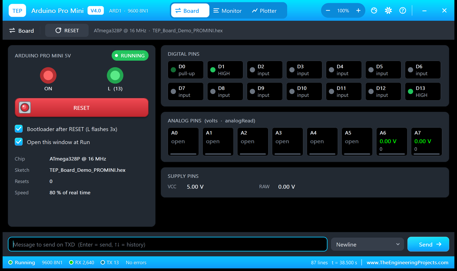
- The board panel: ARDUINO PRO MINI 5V with a RUNNING pill (it says IN RESET or BOOTLOADER at those times), the board's LEDs as they glow on the sheet (here ON and L (13), the names the family uses), the red RESET key (a 20 ms press plus the bootloader), and two options: Bootloader after RESET (L flashes 3x) and Open this window at Run.
- The facts: Chip ATmega328P @ 16 MHz, Sketch TEP_Board_Demo_PROMINI.hex, Resets 0 and Speed 80 % of real time (Proteus's AVR model sets the pace, as with V3.0).
- DIGITAL PINS: D0 - D13, each HIGH, LOW, pull-up or input. Here D0 is pull-up, D1 HIGH (the idle serial line), D13 HIGH (the LED is on at this moment), and the rest are inputs.
- ANALOG PINS (volts · analogRead): A0 - A5 say open: nothing is wired to them, so Proteus has no node to read (the sketch reads 0). A6 and A7, the analog-only pins, show 0.00 V and the count 0.
- SUPPLY PINS: VCC 5.00 V and RAW 0.00 V.
The Monitor Tab
The Monitor tab is the full serial monitor: the serial text in both directions, the line to send (Enter sends it), the line ending, the baud rate and the format, ASCII or HEX view, time stamps, search and save. If your own sketch uses another baud rate, set the board's BAUD property to it, or to AUTO, and the monitor measures the sketch's bits.
The Plotter Tab
The Plotter turns lines of the form name:value, separated by commas, into live traces. The demo's PLOT ON stream sends one such line every 200 ms:
  if (plotOn && (long)(millis() - nextPlotAt) >= 0) {
    nextPlotAt += PLOT_PERIOD_MS;
    float a = sample * 0.15;
    Serial.print(F("sin:"));
    Serial.print(sin(a), 3);
    Serial.print(F(",cos:"));
    Serial.print(cos(a * 0.7), 3);
    Serial.print(F(",ramp:"));
    Serial.println((sample % 40) / 20.0 - 1.0, 2);
    sample++;
  }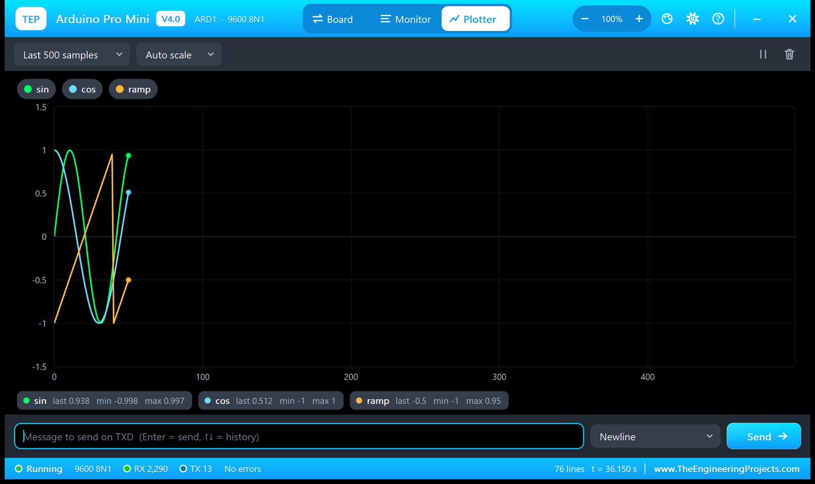
With 0.15 radians per sample, sin repeats about every 42 samples (8.4 s), cos (at 0.7 times the speed) about every 60 samples (12 s), and the ramp climbs from -1 to 0.95 in 40 steps (8 s) and jumps back. The picture was taken after about 50 samples. The chips under the chart give each trace's last, minimum and maximum value: the ramp's last value, -0.5, is sample 50 (50 mod 40 = 10, and 10 / 20 - 1 = -0.5), and its maximum, 0.95, is the top of every ramp (39 / 20 - 1). Above the chart, you choose how many samples to show (here the last 500) and the scale (Auto scale).
Settings and Help
The gear opens Settings. The ? icon opens Help & Support, with eight cards and their links:
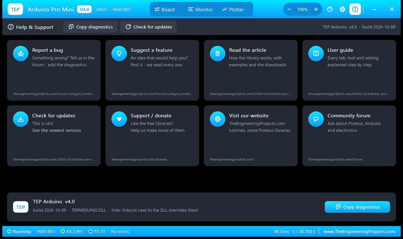
- Report a bug and Suggest a feature open the forum board shared by all six boards.
- Read the article, User guide and Check for updates (This is v4.0) open this post: each board's monitor opens its own board's post.
- Support / donate, Visit our website and Community forum open our website.
- Copy diagnostics copies a diagnostics text to paste into a bug report, and a
links.inifile next to the DLL can change the links.
Your Own Sketch on the Arduino Pro Mini in Proteus
- In the Arduino IDE, select Tools > Board > Arduino Pro or Pro Mini, and Tools > Processor > ATmega328P (5V, 16 MHz).
- Choose Sketch > Export Compiled Binary. Use the .hex file without "with_bootloader" in its name.
- Double-click the board in Proteus and set Upload Hex File to that .hex file. Press Run.
Note: Pick the 5 V, 16 MHz processor. The model runs at 16 MHz, and a sketch built for the 3.3 V, 8 MHz board would run its timing, and its baud rate, twice too fast.
Now wire your parts as on a real Pro Mini: power them from VCC and GND, and use the pins from the tables above. A sensor on A4 / A5 talks I2C, an SPI module goes on D10 - D13, and a serial module goes on TXO / RXI (set MONITOR=NO if it should have D0 / D1 to itself). To rebuild the demo itself, open TEP_Board_Demo.ino, select the same board and export it again.
Things to Know Before Using a Real Pro Mini
The demo sketch uses only the Arduino core, so it runs on a real 5 V Pro Mini, too. Keep in mind:
- You need a USB-to-serial adapter to upload: a 5 V FTDI-style adapter for the 5 V board. Plug it in with BLK to BLK and GRN to GRN.
- No DTR, no auto-reset: if your adapter has no DTR pin, press the reset button just as the upload starts.
- Power: RAW takes up to 12 V into the small regulator, or you feed a regulated 5 V straight into VCC. SparkFun's regulator gives about 150 mA, so power motors, servos and long LED strips separately. In Proteus, VCC has no current limit.
- The serial monitor: the real board has no built-in monitor; on the bench, the Arduino IDE's Serial Monitor talks to it through the adapter. The demo's commands work the same there.
- A6 / A7 are analog inputs only, on the real board and in Proteus.
- The bootloader: after a reset, a real board waits about a second for an upload before the sketch starts; its L pattern can differ from the 3 flashes the model shows on every board.
Troubleshooting
- The board does not simulate, no LEDs light:
TEPARDUINO.DLLis missing from the MODELS folder and from the project folder. - No monitor window: click the FTDI header (the left end), or check MONITOR=YES. Proteus's Debug menu also lists the window.
- The monitor shows nothing or garbage: the sketch's
Serial.begin()and the BAUD property differ: set BAUD to the sketch's rate, or AUTO. Garbage at the right baud rate? Check that you built the sketch for the 5 V, 16 MHz Pro Mini. - A Virtual Terminal on D0 / D1 shows the text twice or fights the monitor: set MONITOR=NO on the board.
- An analog tile says "open": nothing is wired to that pin, so Proteus has no node to read (the sketch reads 0).
- The 13 LED only glows faintly: pin 13 is still an input with its pull-up on (a
digitalWrite(13, HIGH)withoutpinMode(13, OUTPUT)does exactly that); callpinMode(13, OUTPUT)first. - Your sketch waits for a pin-change interrupt and nothing happens: Proteus 8.5's AVR model did not run pin-change interrupts in our tests. Use
attachInterrupt()on D2 (INT0) or D3 (INT1), ordigitalRead(). - A V3.0 design does not fit: the pin positions changed; place the V4.0 board and wire it again.
- Red and grey squares beside the pins: Proteus's logic-state markers, not part of the board.
Limitations of the Simulation
- Modelled: the ATmega328P (Proteus's own AVR model), the PWR and 13 LEDs, the RESET button with the bootloader's flashes and its 1 s wait, the GRN (DTR) reset, the VCC supply and the grounds, and the built-in serial monitor on D0 / D1.
- Not modelled: the regulator and its RAW input (RAW is a load), a current limit on VCC, the 3.3 V / 8 MHz version and the bootloader's own code: you load sketches with Upload Hex File, not over the serial port. The board is drawn 1.4 inches long, a little longer than the real 1.3 inches.
- The board model, the drawing and the built-in monitor are our own work; the drawing follows SparkFun's board. Arduino is a trademark of Arduino SA. The HEX file contains the Arduino AVR core 1.8.6, which includes LGPL-licensed code; its source code is on GitHub.
- Tested in Proteus 8.5 in October 2026 with the demo project as shipped and the built-in monitor: PWR lit, 13 blinking; RESET held: the chip in reset and 13 dark; VCC 5.00 V; READ answered A0 - A7; PLOT ON drew the traces; about 80 % of real time on our PC with the monitor open and the plot stream running. The GRN (DTR) pin is connected to the model and uses the same reset path as the Board tab's RESET key, which we tested; a DTR edge itself was not driven in our Proteus run. The library generator also checks the board: no two parts or texts overlap, every text sits on the board, and the pin positions and V3.0's pin order are right.
So, that was all about the Arduino Pro Mini Library for Proteus V4.0. I hope the working LEDs, the RESET button with its bootloader, the FTDI header and the built-in serial monitor make the little Pro Mini much easier to try out, so your sketch works the first time you plug a real board into its FTDI adapter. If you use the Arduino Pro Mini Library for Proteus in a project, please share your feedback in the comments or in our forum, and if you have any questions, ask in the comments and I will help you out. Till the next tutorial, take care and have fun!
Comments
0