


nRF7002 DK Library for Proteus: Wi-Fi 6 Web Thermostat Simulation


Hello friends, I hope you all are doing great. Today, I am going to share the nRF7002 DK Library for Proteus, so you can run a Wi-Fi 6 simulation of Nordic Semiconductor's first Wi-Fi development kit. The nRF7002 DK pairs Nordic's nRF5340 Bluetooth chip with the nRF7002, a low-power Wi-Fi 6 companion IC, and it is the board research teams use to bring Wi-Fi into battery-powered IoT products. With this library it runs your Arduino sketch in Proteus 8.5, joins a Wi-Fi network, serves web pages to a phone, and its two LEDs and two buttons work with a click.
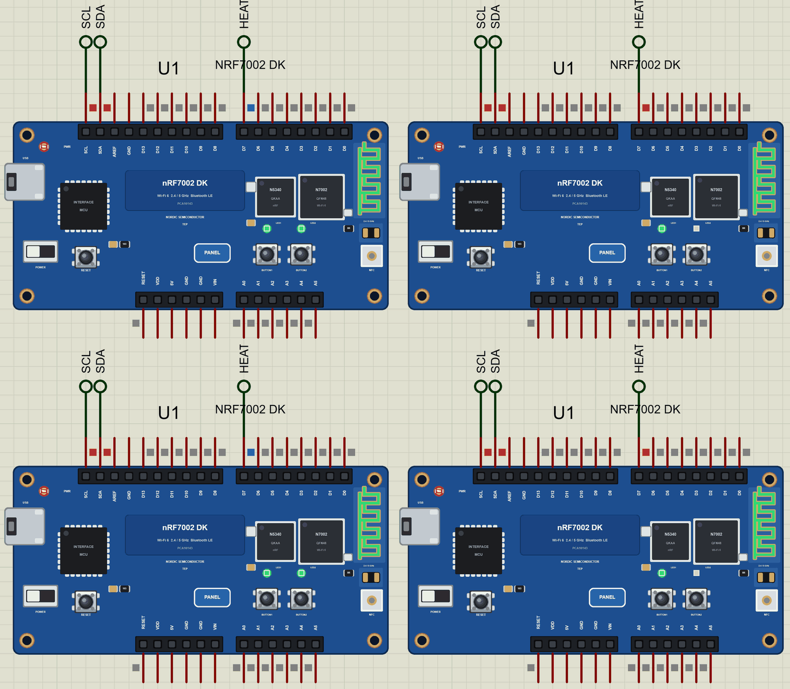
nRF7002 DK Library for Proteus
Latest version: V1.0 (November 2026, this tutorial)
Helping Tools
- Laptop WiFi Monitor: a laptop on the Wi-Fi of your design: a browser, a TCP / UDP terminal and ping
- Mobile WiFi Monitor: a smartphone that opens the pages of your board and sends it commands
- Serial Monitor Advance: a serial terminal window for the UART of your board
For the demo we built a Wi-Fi web thermostat. An SHT31 sensor measures the room, a relay switches the heater, and the board serves a web page that any phone or laptop on the network can open to read the room and change the setpoint. It is the kind of small, useful device that Wi-Fi 6 was designed to keep online for a long time on very little power.
NOTICE: Proteus has no nRF5340 or nRF7002 model, so our team has put a lot of effort into building this board ourselves: the DK's Arduino header, the LEDs, the buttons, Wi-Fi and Bluetooth LE are all our own model, and your sketch compiles with our free TEP Boards for Proteus add-on. Your feedback is the fuel that keeps us going, so please tell us what you think in the comments below. And if our free libraries help you, you can buy us a coffee. So, let's get started with the nRF7002 DK Library for Proteus:
What is the nRF7002 DK?
The nRF7002 DK (its board number is PCA10143) is Nordic Semiconductor's development kit for the nRF7002 Wi-Fi companion IC. It keeps the shape of Nordic's other DKs, with an Arduino Uno header, an on-board debugger with its own USB port, two LEDs and two buttons. On it, the nRF5340 runs your application and Bluetooth LE, and talks to the nRF7002 over a fast QSPI bus; the nRF7002 handles Wi-Fi on both the 2.4 GHz and the 5 GHz bands, through a dual-band antenna at the end of the board.
| Feature | The real nRF7002 DK | In the library |
|---|---|---|
| Host | nRF5340: two Arm Cortex-M33 cores, Bluetooth LE | your Arduino sketch, ArduinoBLE |
| Wi-Fi | nRF7002: Wi-Fi 6, 2.4 and 5 GHz | WiFi and WebServer on our network |
| Memory | 1 MB flash, 512 KB RAM on the host | about 256 KB of flash, 8 KB of RAM |
| On the board | two LEDs, two buttons, RESET, power switch | all of them, animated |
| Header | Arduino Uno Rev3 layout, 3.3 V logic | the same pins and labels |
What Is New in Wi-Fi 6?
Wi-Fi 6 (802.11ax) is usually sold as faster Wi-Fi for laptops, but two of its features matter more for small devices. OFDMA lets the router talk to many devices in the same moment, each in its own slice of the channel, so a home full of sensors does not queue up for air time. Target Wake Time lets a device agree with the router on when it will wake up; between those moments it can sleep deeply instead of listening all the time. That is how a Wi-Fi sensor can last months or years on a battery, which classic Wi-Fi never allowed.
Why a Companion Chip?
Most Wi-Fi microcontrollers put the processor and the radio in one chip. Nordic chose a companion design instead: the nRF7002 does only Wi-Fi, and any Nordic host, such as the nRF5340, runs the application and Bluetooth. The product team can then pick the host that fits its battery and its budget, add Wi-Fi only where it is needed, and keep one software platform for Bluetooth, Thread and Wi-Fi products alike. The nRF7002 can also scan for Wi-Fi networks without joining them, which helps a tracker find its position from the names of the networks around it.
Where Is It Used?
The nRF7002 DK is the starting point for products that need Wi-Fi only now and then: smart-home sensors and thermostats that report to a home network, Matter devices that join over Wi-Fi, asset trackers that use Wi-Fi scanning for their position, and wearables that sync a day of data when they get home. In research labs it is popular for power studies: a team can measure how long a sensor lasts with Target Wake Time against classic power save, or what a Bluetooth LE link plus a short Wi-Fi burst costs against staying on Wi-Fi all day. Because the host and the radio are separate chips, it is also used to study coexistence, the scheduling that lets Bluetooth and Wi-Fi share the 2.4 GHz band on one board without spoiling each other's packets.
A simulation cannot measure microamps, but it lets you build and test the whole logic of such a device first: the sensor readings, the decisions, the web page or the Bluetooth service, and what the user sees. When the logic works in the Proteus simulation, moving the sketch to the real board is much quicker.
How a Board Serves a Web Page
A web page from a microcontroller is simpler than it sounds. The board joins the network and gets an IP address, here 192.168.1.101. A web server listens on port 80, and each address on it, such as / or /warmer, calls a small function in the sketch. The function builds the page as text and sends it back. A phone's browser only has to open the address. Our Mobile WiFi Monitor is that phone in Proteus.
Features of the nRF7002 DK Library for Proteus
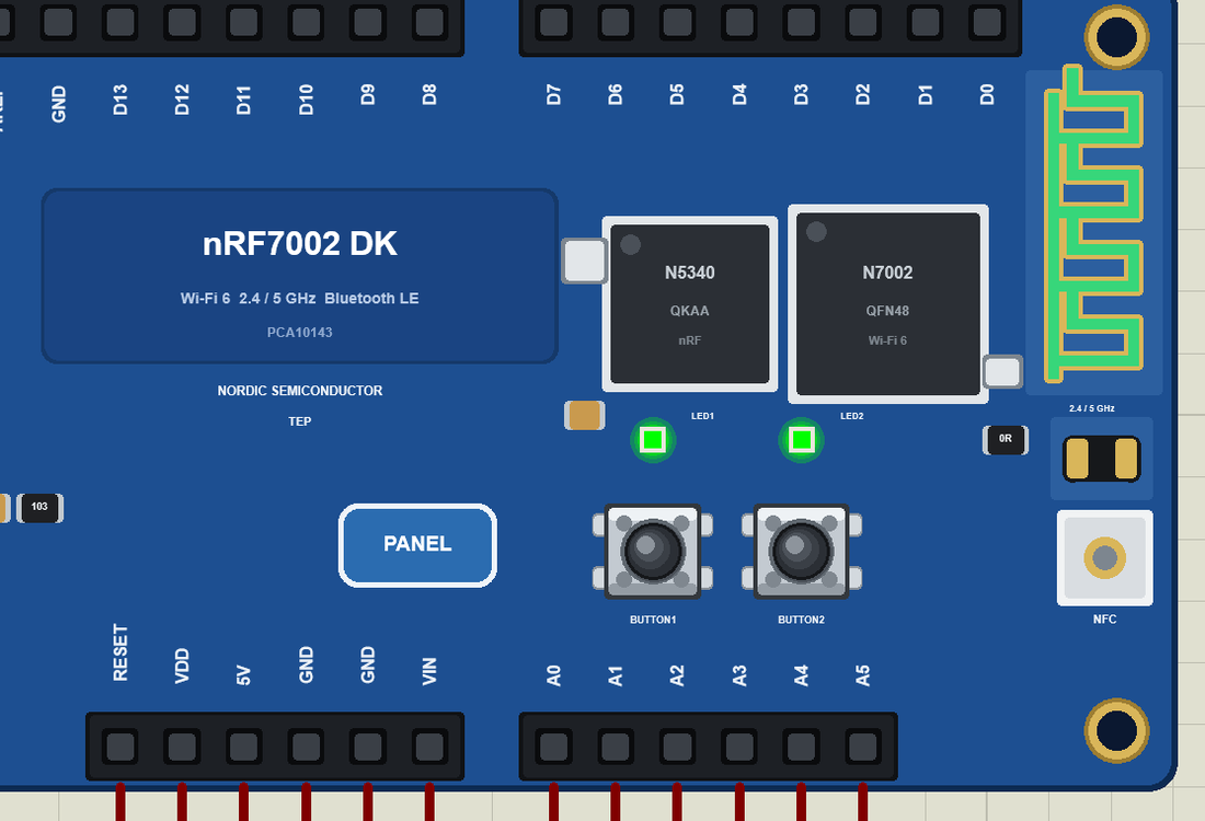
- The board as it looks: the blue DK with its headers, the nRF5340 and the nRF7002, the dual-band Wi-Fi antenna, the 2.4 GHz chip antenna, the interface MCU and USB port, the PANEL pad, two LEDs and two buttons, drawn compact, with our small TEP signature.
- Your sketch: a .hex for "Nordic nRF7002 DK (TEP Proteus)" with the DK's pin names, LED1 / LED2 and BUTTON1 / BUTTON2.
- Wi-Fi: the board package's WiFi and WebServer libraries on our network; the antenna glows with the traffic and the PANEL pad opens the Wi-Fi panel.
- Bluetooth LE: ArduinoBLE, with our phone as the central.
- Real LEDs and buttons: the LEDs light when HIGH, as on the real DK; the buttons are clicked on the board.
- A complete package: about 4.3 MB with the part, the add-on, the SHT31, relay and phone libraries and the demo, without the source code of the models.
The nRF7002 DK in Proteus Simulation
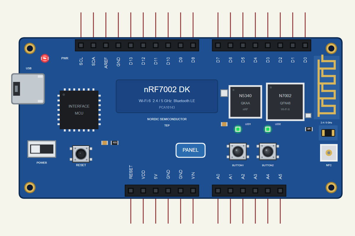
Search NRF7002 in Pick Devices; the device is in TEPNRF7002DK.LIB (Microprocessor ICs, Bluetooth Boards), with the prefix U. Click the USB port for the serial monitor and the PANEL pad for the Wi-Fi panel. The board shares its header and its pin numbers with our nRF52840 DK Library for Proteus.
The Pins
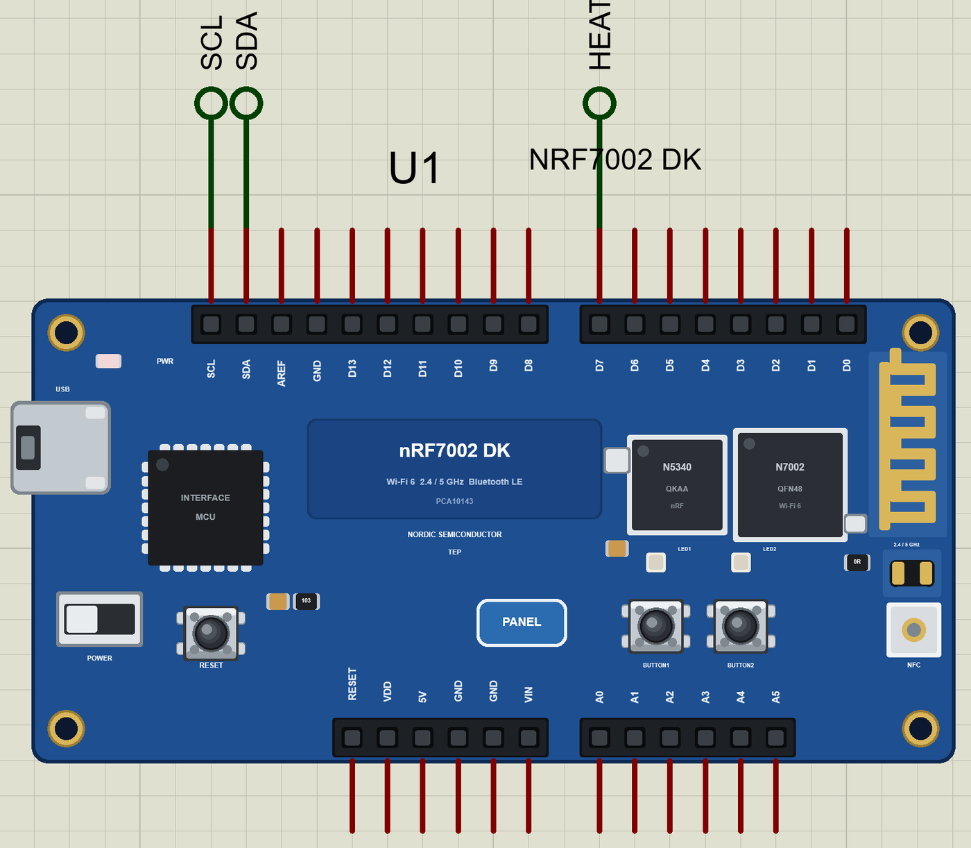
| Pins | What the library does with them |
|---|---|
| D0, D1 | Serial1 RX and TX, or GPIO |
| D2 to D13 | GPIO, PWM with analogWrite, attachInterrupt |
| D10 to D13 | SPI: SS, MOSI, MISO, SCK |
| A0 to A5 | analogRead 0 to 1023 for 0 to 3.3 V, or GPIO |
| SDA, SCL | Wire, the I2C bus |
| VDD, 5V, GND, RESET | the supply and the reset |
The LEDs and the Buttons
LED1 and LED2 light when the pin is HIGH; on the real DK they sit on P1.06 and P1.07. BUTTON1 and BUTTON2 are the two push buttons (P1.08 and P1.09); use pinMode(BUTTON1, INPUT_PULLUP), and a button reads LOW while you hold it down with the mouse in the simulation.
Download nRF7002 DK Library for Proteus
Click the button below to download nRF7002-DK-Library-for-Proteus-v1.0.zip (about 4.3 MB, without the source code of the models):
nRF7002 DK Library for Proteus V1.0- README.txt: installation, the demo, the pins, the properties, troubleshooting and the limits.
- Proteus Library Files:
TEPNRF7002DK.LIBand the demo's parts:TEPSHT31.LIB,TEPRELAY.LIB,TEPMOBILE.LIBandTEPLAPTOP.LIB. - Proteus Model Files:
TEPNET.DLL,TEPSHT31.DLLandTEPRELAY.DLL. - Arduino Code: the demo sketch and the TEP Boards for Proteus add-on 1.63.0, with WiFi, WebServer and ArduinoBLE.
- Proteus Simulation: the demo project, its HEX file and copies of the DLLs.
No Proteus yet? Read How to Download and Install Proteus 7 and 8. New to libraries? Follow How to Install a New Library in Proteus.
How to Install nRF7002 DK Library for Proteus
- Close Proteus and extract the whole zip file, for example to your Desktop.
- Copy the files from Proteus Library Files into the LIBRARY folder of Proteus.
- Copy the DLLs from Proteus Model Files into the MODELS folder, replacing an older TEPNET.DLL.
- Delete
TEPNRF7002DK.IDXfrom the LIBRARY folder if it is there. - For your own sketches, copy Arduino Code\TEP Boards for Proteus\hardware into your Arduino sketchbook (Documents\Arduino) and restart the Arduino IDE; the board is Nordic nRF7002 DK (TEP Proteus). Install Adafruit SHT31 Library and Adafruit BusIO from the Library Manager.
- Start Proteus, press P and search for NRF7002.
Demo: a Wi-Fi Web Thermostat in Simulation
A thermostat is the classic connected-home device: a sensor, a heater and a person who wants to change the temperature from the sofa or from work. Ours needs no app and no cloud. It serves its own web page, so any phone or laptop on the same Wi-Fi can open it.
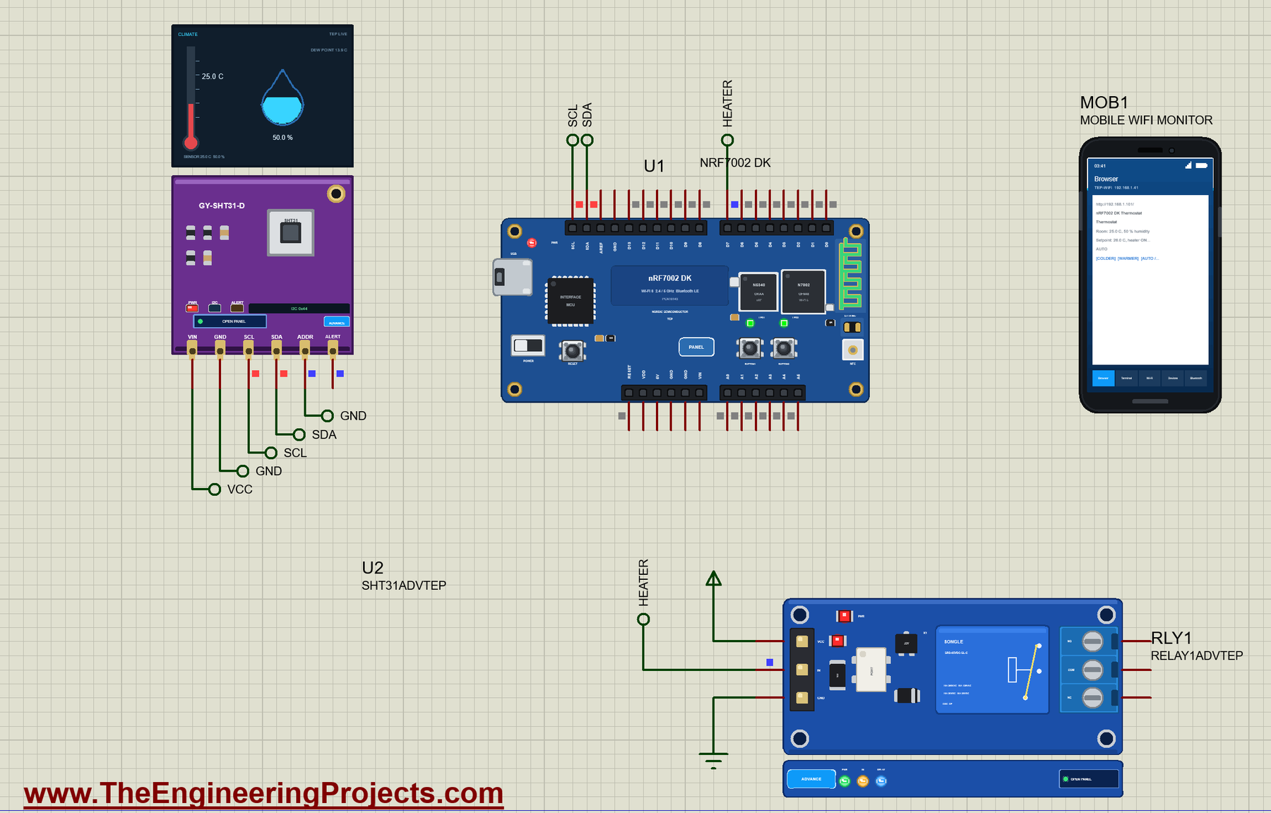
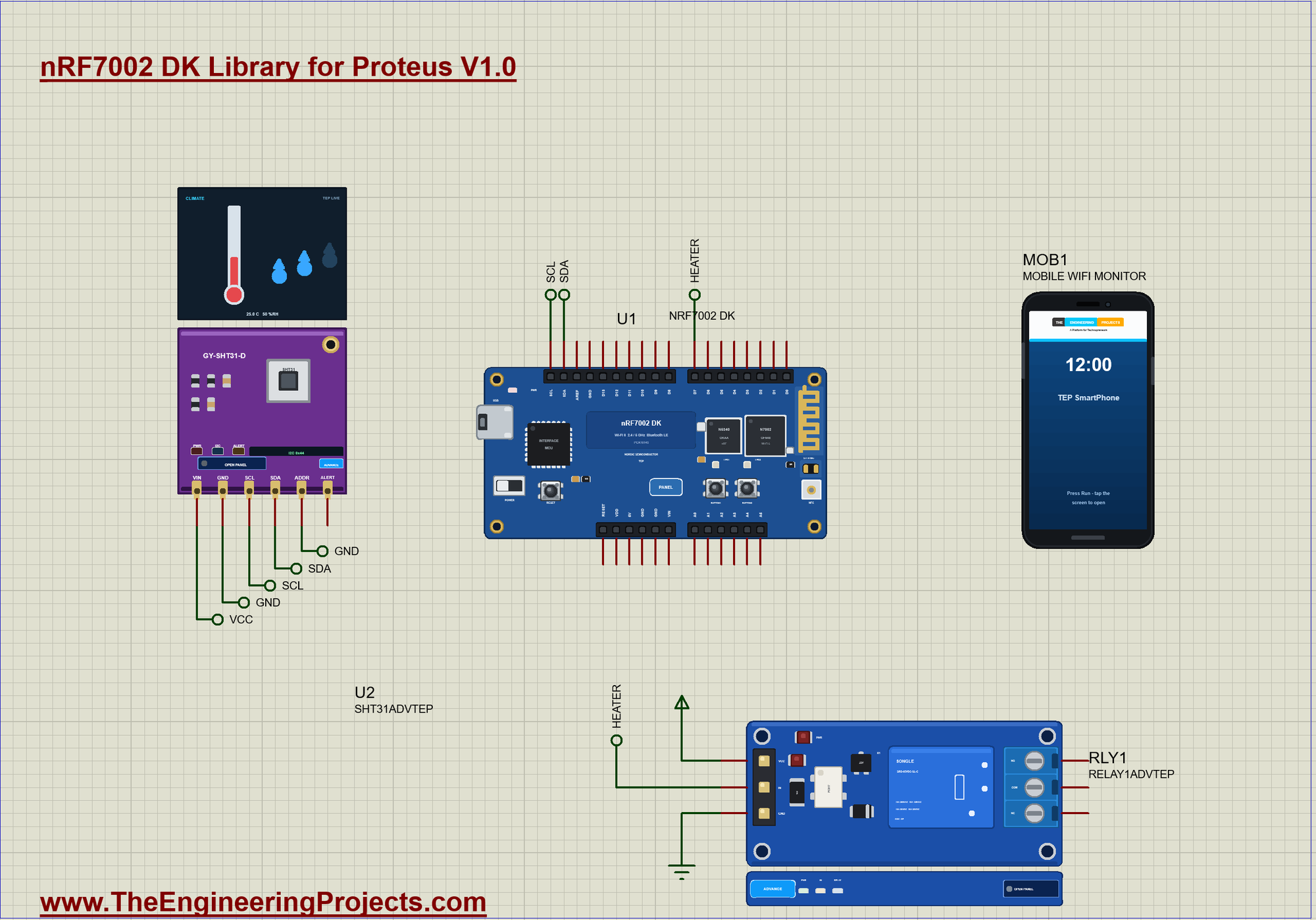
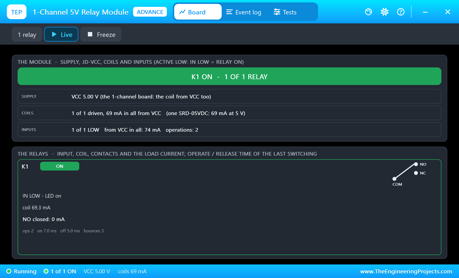
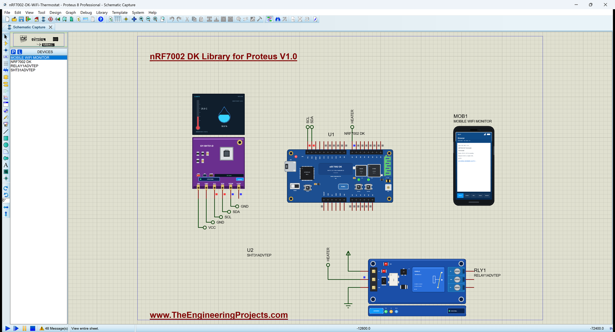
Open nRF7002-DK-WiFi-Thermostat.pdsprj. U1 runs DK_WiFi_Thermostat.hex. U2 is the SHT31 and RLY1 comes from our Relay Module Library, both in the Advance version. MOB1 is the phone, whose browser opens the board's page. The serial monitor is the same window as our TEP Serial Monitor Advance for Proteus.
The Wiring
The SHT31's SDA and SCL go to the DK's SDA and SCL pins, and its ADDR pin goes to GND, which selects the address 0x44. The relay's IN pin is on D7 through the label HEATER. This relay module switches on when its input is LOW, so the sketch writes HIGH to the pin before it makes it an output, and the heater never flickers at power-up.
Joining Wi-Fi
setup() calls WiFi.begin() with the network's name and password and waits until the status is WL_CONNECTED, blinking LED1 meanwhile. Then it registers one function per address and starts the server:
  WiFi.begin(ssid, pass);
  bool blink = false;
  while (WiFi.status() != WL_CONNECTED) { blink = !blink; led(0, blink); delay(300); }   // LED1 blinks while Wi-Fi connects
  led(0, true);
  Serial.print(F("Wi-Fi connected, IP ")); Serial.println(WiFi.localIP());
  server.on("/", handleRoot); server.on("/json", handleJson);
  server.on("/colder", handleColder); server.on("/warmer", handleWarmer); server.on("/mode", handleMode);
  server.begin();
The Thermostat
control() is a classic thermostat with a band of 1 C: the heater goes on below the setpoint minus 0.5 C and off above the setpoint plus 0.5 C. Without the band the relay would click on and off around a single temperature all day:
void control() {                                            // AUTO: a thermostat with a 1 C band
  if (!autoMode) { setHeater(false, F("mode OFF")); return; }
  if (tempC < setpoint - BAND) setHeater(true, F("too cold"));
  else if (tempC > setpoint + BAND) setHeater(false, F("warm enough"));
}
The Two Buttons
The DK's BUTTON1 and BUTTON2 read LOW when pressed, so the pins use INPUT_PULLUP. handleButtons() acts only on the change to LOW, so one press moves the setpoint once, however long the button is held:
void handleButtons() {
  for (byte k = 0; k < 2; k++) {
    const bool now = digitalRead(BUTTONS[k]);
    if (now == lastButton[k]) continue;
    lastButton[k] = now;
    if (now != LOW) continue;                               // act on the press
    if (k == 0) setSetpoint(setpoint - 0.5, F(">> BUTTON1"));
    else setSetpoint(setpoint + 0.5, F(">> BUTTON2"));
  }
}
The Web Page
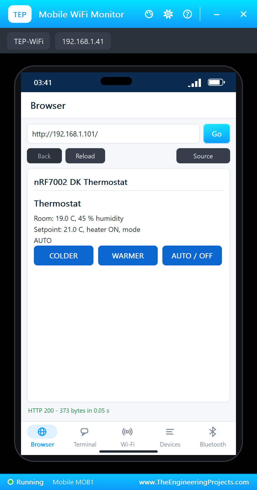
handleRoot() builds the page as one string: the room, the setpoint, the heater and the mode, and three links. Each link calls its own handler, which changes the setpoint or the mode and then sends the page again:
void handleRoot() {
  String h = "<html><head><title>nRF7002 DK Thermostat</title></head><body><h1>Thermostat</h1>";
  h += "<p>Room: <b>" + String(tempC, 1) + " C</b>, " + String(humidity, 0) + " % humidity</p>";
  h += "<p>Setpoint: <b>" + String(setpoint, 1) + " C</b>, heater <b>" + String(heater ? "ON" : "OFF") + "</b>, mode " + String(autoMode ? "AUTO" : "OFF") + "</p>";
  h += "<p><a href=\"/colder\">COLDER</a> <a href=\"/warmer\">WARMER</a> <a href=\"/mode\">AUTO / OFF</a></p></body></html>";
  server.send(200, "text/html", h);
}
A second address, /json, returns the same values in JSON for programs, for example a laptop script that logs the temperature every minute.
Run the Simulation
Press Run. LED1 blinks while the board joins TEP-WiFi, then stays on; the monitor shows the address of the page. The room starts at 19 C, below the 21 C setpoint, so the heater goes on at once and LED2 lights:
nRF7002 DK Wi-Fi 6 Web Thermostat - The Engineering Projects
Connecting to TEP-WiFi
Wi-Fi connected, IP 192.168.1.101
Thermostat page: http://192.168.1.101/
BUTTON1 / BUTTON2 = setpoint -/+ 0.5 C
>> Heater ON (too cold)
Room: 19.0 C  45 %  set 21.0 C  heater ON  auto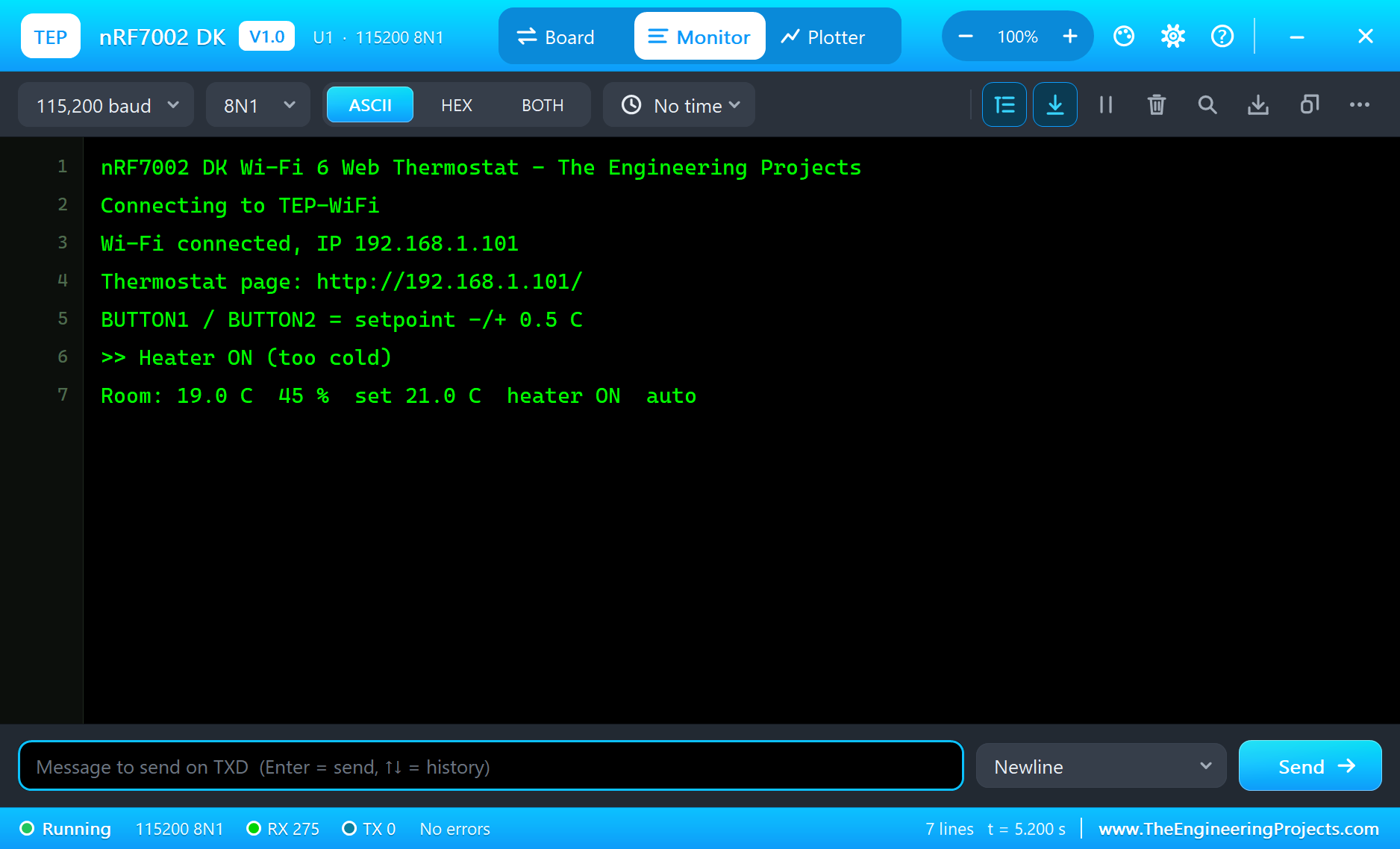
Open the Page
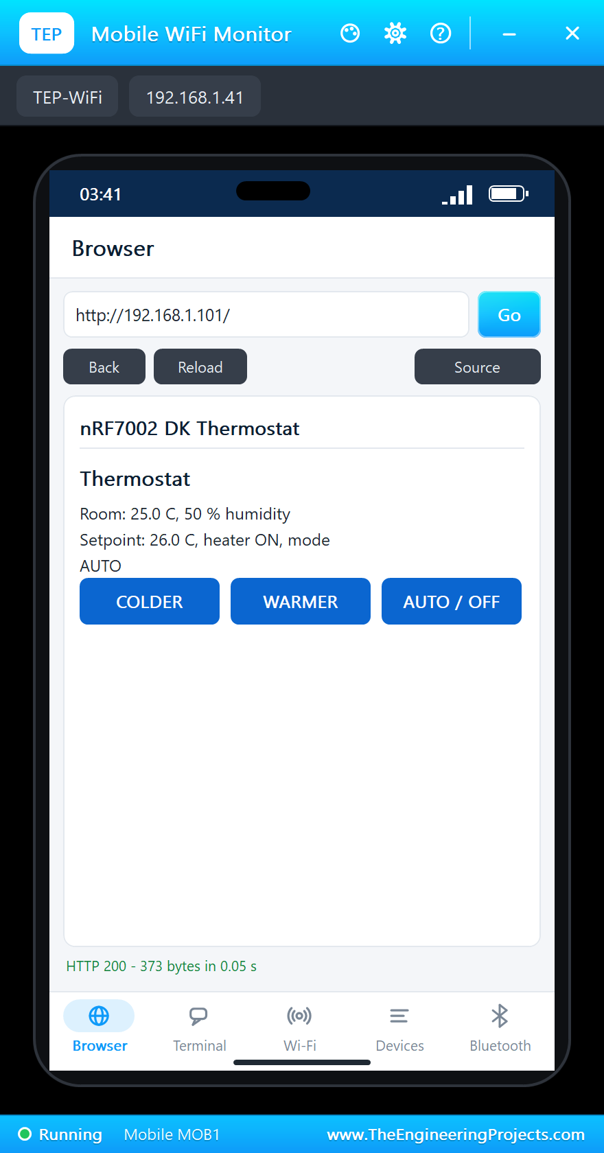
Click the phone and press Go: the browser opens http://192.168.1.101/ and shows the thermostat:
A Warmer Room
Open the SHT31's pop-up and click the ROOM scene: the room jumps to 25 C and 50 %, well above the 21 C setpoint, and the heater goes off:
Room: 19.0 C  45 %  set 21.0 C  heater ON  auto
>> Heater OFF (warm enough)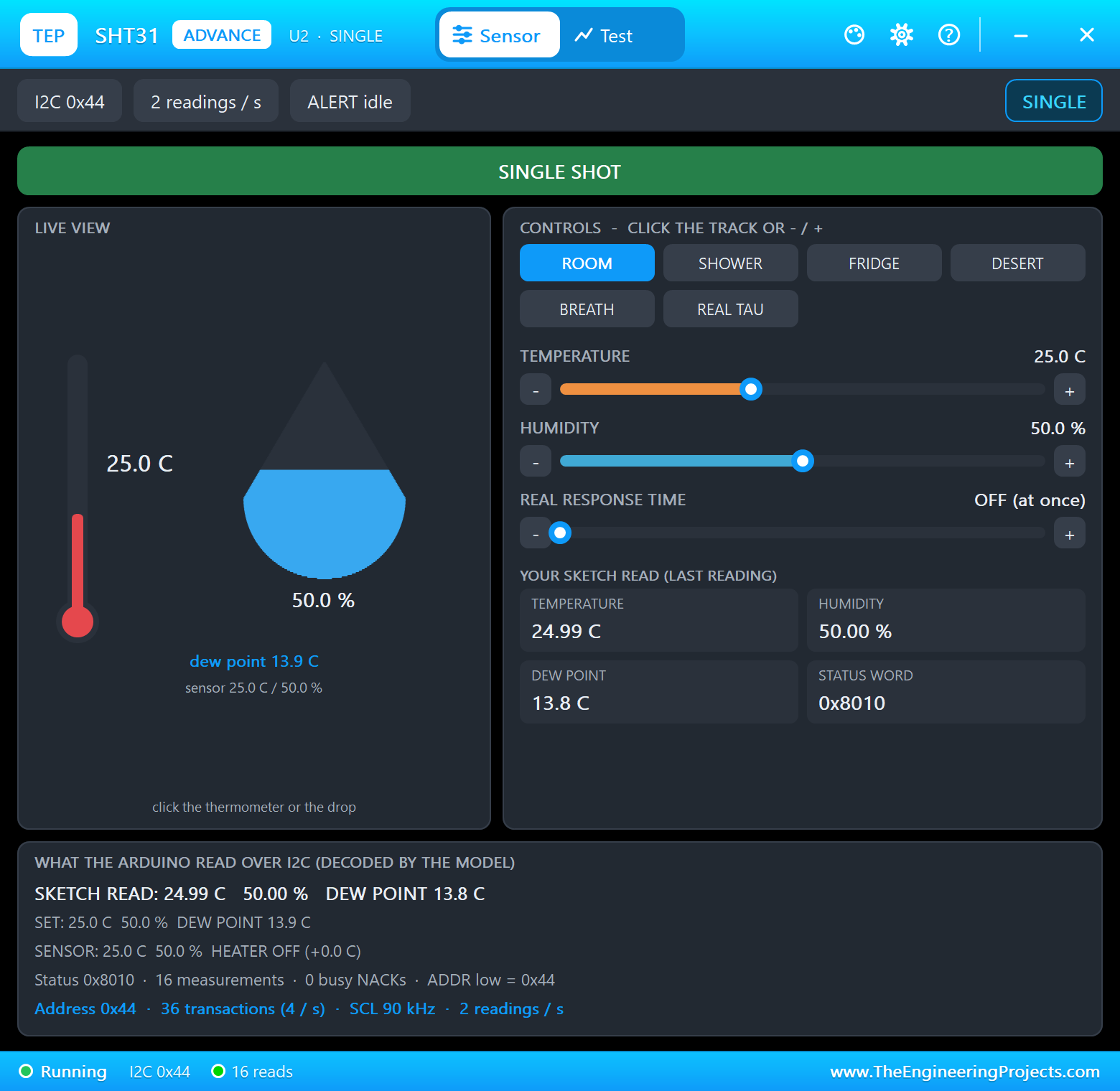
Turn It Up
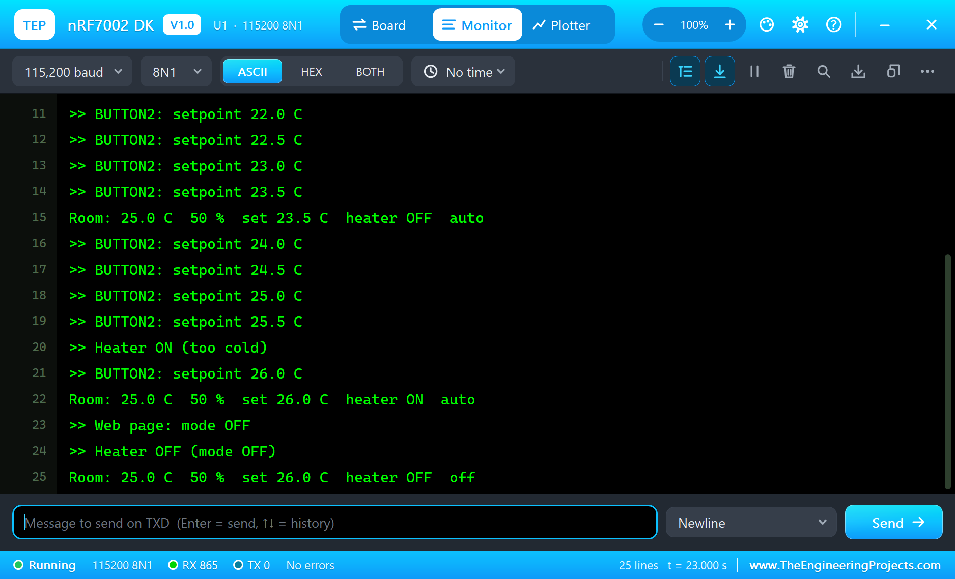
Click BUTTON2 ten times. The setpoint climbs in 0.5 C steps to 26.0 C; at 25.5 C the room is too cold again and the heater comes back on:
>> BUTTON2: setpoint 21.5 C
>> BUTTON2: setpoint 22.0 C
>> BUTTON2: setpoint 22.5 C
>> BUTTON2: setpoint 23.0 C
>> BUTTON2: setpoint 23.5 C
Room: 25.0 C  50 %  set 23.5 C  heater OFF  auto
>> BUTTON2: setpoint 24.0 C
>> BUTTON2: setpoint 24.5 C
>> BUTTON2: setpoint 25.0 C
>> BUTTON2: setpoint 25.5 C
>> Heater ON (too cold)
>> BUTTON2: setpoint 26.0 C
Room: 25.0 C  50 %  set 26.0 C  heater ON  auto
Reload the page and the phone shows it:
Here is the complete circuit while the simulation runs:
Switch It Off from the Phone
Tap AUTO / OFF on the page. The mode changes to OFF, the heater goes off and LED2 goes out:
>> Web page: mode OFF
>> Heater OFF (mode OFF)
Room: 25.0 C  50 %  set 26.0 C  heater OFF  off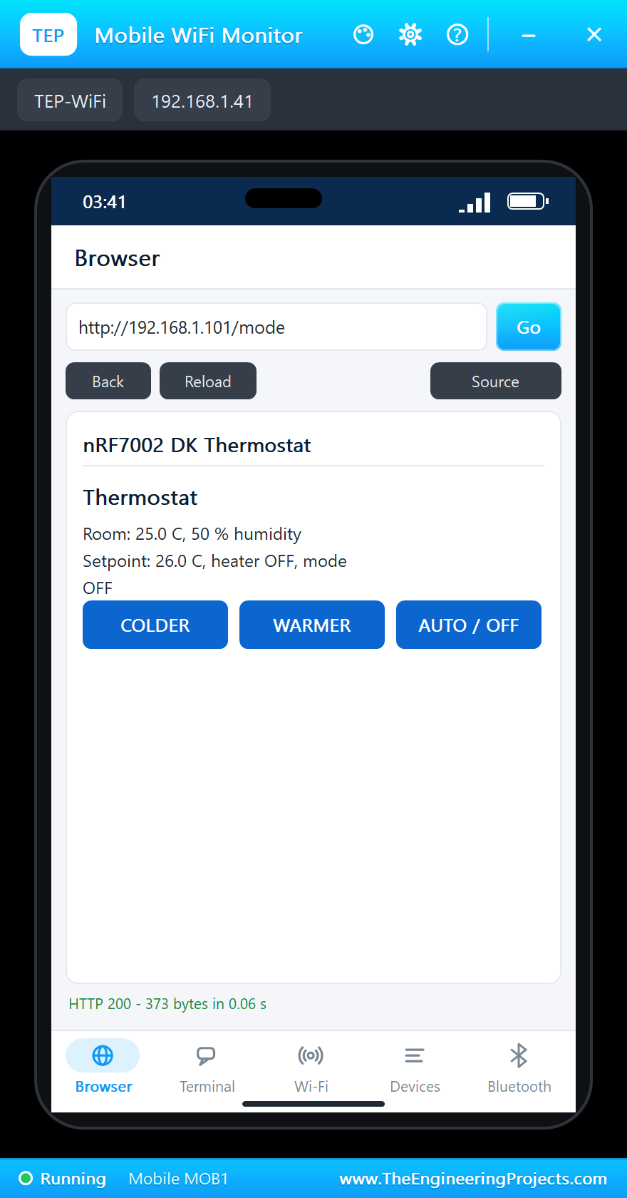
Try It Yourself
- Change
BANDto 0.2 and watch how much more often the relay switches. - Add a
/set?c=22address that takes the setpoint as a number. - Show the heater's running time today on the page.
- Make LED1 blink slowly while the heater is on, so you can see both from across the room.
Ideas to Extend the Thermostat
- Add a night setback: a lower setpoint between 23:00 and 06:00, with the time from an NTP server.
- Advertise the temperature over Bluetooth LE too, with ArduinoBLE, for a phone with no Wi-Fi.
- Log the last 24 hours in an array and draw them as a small chart on the page.
- Add a window contact: the heater stays off while the window is open.
Your Own Sketches
Write the sketch in the Arduino IDE with the board Nordic nRF7002 DK (TEP Proteus), use Sketch > Export Compiled Binary and set the part's PROGRAM property to the .hex. The WiFi and WebServer calls are the familiar Arduino ones. On a real board, Nordic's nRF Connect SDK provides the Wi-Fi driver, the network stack and an HTTP server; the structure of your program, connect, serve, react, stays the same.
Things to Know Before Using a Real nRF7002 DK
- 3.3 V logic: the header pins are not 5 V tolerant, so check a shield before you plug it in.
- Wi-Fi needs memory: a real Wi-Fi stack uses a good part of the nRF5340's RAM, so plan your buffers.
- 2.4 or 5 GHz: 5 GHz is less crowded but reaches less far through walls; let the router choose, or test both.
- Security: a real device on a home network should use HTTPS or at least a password on its page.
- Mains needs care: a relay that switches a real heater carries dangerous voltage, so use a safe enclosure.
Properties of the nRF7002 DK
| Property | What it does |
|---|---|
| PROGRAM | the sketch: a .hex from TEP Boards for Proteus (board "Nordic nRF7002 DK") |
| MONITOR, BAUD, AUTOOPEN | the built-in serial monitor: on, its baud rate (115200), open at Run |
Troubleshooting
- The board never connects: the network is TEP-WiFi with the password 12345678; wait for
WL_CONNECTED. - The phone shows no page: press Go or Reload after the monitor prints the page's address.
- "SHT31 not found": the sensor is at 0x44 with ADDR on GND; check SDA and SCL.
- The heater acts backwards: the relay module switches on when IN is LOW.
- A number goes wrong above 32767: int is 16 bits in the simulation - use long.
Limitations of the Simulation
- Wi-Fi joins our simulated network: there is no real router, no 5 GHz channel choice and no Target Wake Time.
- Bluetooth LE works as a peripheral only. Your sketch is one program: the nRF5340's two cores are not split. Matter, Thread, NFC and the QSPI flash are drawn, not modelled.
- Your sketch gets 8 KB of RAM in the simulation, and int is 16 bits there.
- nRF7002, nRF5340 and Nordic Semiconductor are names of Nordic Semiconductor ASA, Arduino of Arduino, Wi-Fi of the Wi-Fi Alliance, and the Bluetooth word mark belongs to Bluetooth SIG; this library is not made or endorsed by them or by Labcenter.
- Tested in Proteus 8.5 in November 2026 (the demo as shipped, about 23 s of simulation). Proteus 7 is not supported.
So, that was all about the nRF7002 DK Library for Proteus. I hope it helps you try your Wi-Fi IoT ideas in a simulation before you buy a board - the network, the web page, the sensor and the relay, all on one sheet. If you have any questions, ask in the comments and I will help you out. Till the next tutorial, take care and have fun!

Comments
0