


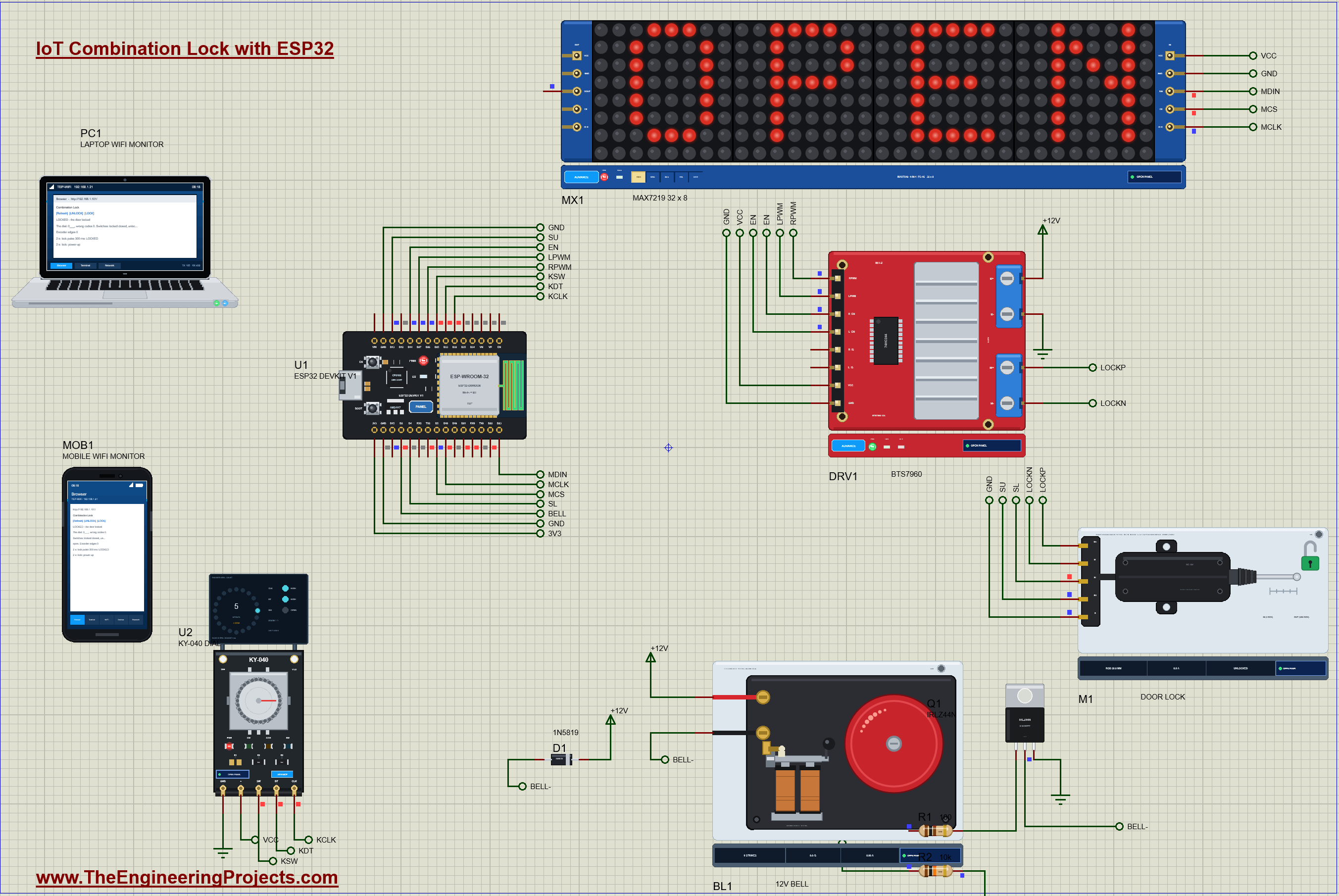
IoT Combination Lock with ESP32 - Proteus Simulation


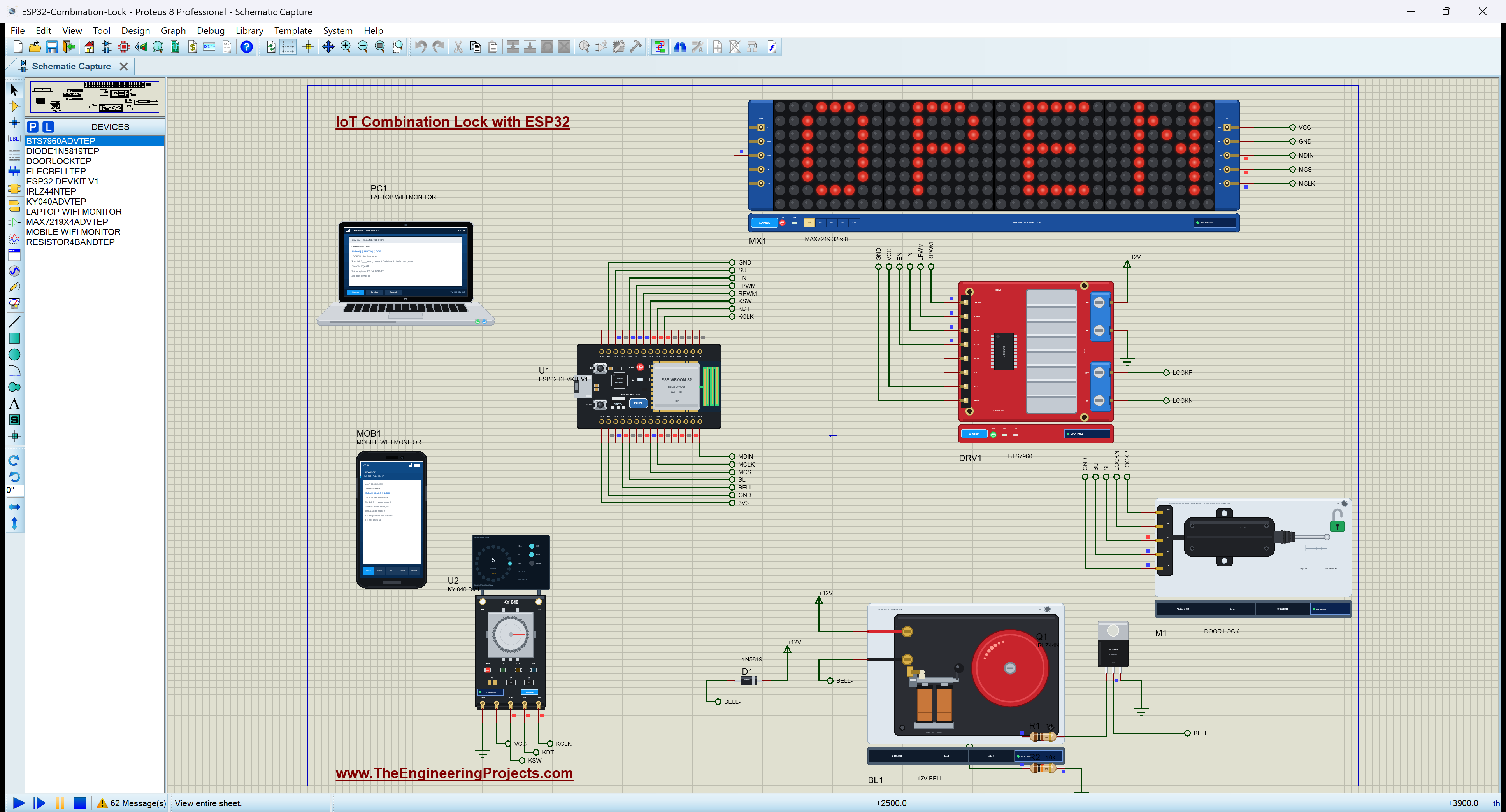
Hello friends, I hope you all are doing great. Today, I am going to share the IoT Combination Lock with ESP32 - Proteus Simulation, the thirty-first project of our IoT Projects series. If you have searched for a Proteus simulation of an ESP32 combination lock with a rotary encoder dial, here is a complete one. An ESP32 DevKit V1 turns a KY-040 rotary encoder into a safe's dial: you turn it to choose each digit and press it to enter the digit, a MAX7219 LED matrix shows the code as you go, a BTS7960 H-bridge drives a real car door lock actuator, an electric bell rings after three wrong codes, and a web dashboard can unlock and lock the door from a laptop or a phone.
A rotary encoder looks like a potentiometer but works like two switches: as you turn it, they open and close in a set order, and the order tells the direction. In this tutorial, we will go through the circuit, learn how quadrature works and how to read it without being fooled by contact bounce, drive a MAX7219 LED matrix over SPI with our own font, pulse a door lock actuator through an H-bridge and check its end switches, switch a 12 V bell with a logic-level MOSFET, walk through the Arduino sketch, and then run the simulation: the right code, a remote unlock and lock, and three wrong codes that ring the bell. At the end, you can download the project with the sketch and every library file.
NOTICE: Our team has put a lot of effort into this project: the circuit, the code and every part in the simulation are our own work, and you get them all free. Your feedback is the fuel that keeps us going, so please tell us what you think in the comments below. And if our free projects help you, you can buy us a coffee. So, let's get started with the IoT Combination Lock with ESP32 - Proteus Simulation:
What Does This Combination Lock Do?
- A dial like a safe's: turn the KY-040 to choose a digit, press it to enter the digit, four digits in all.
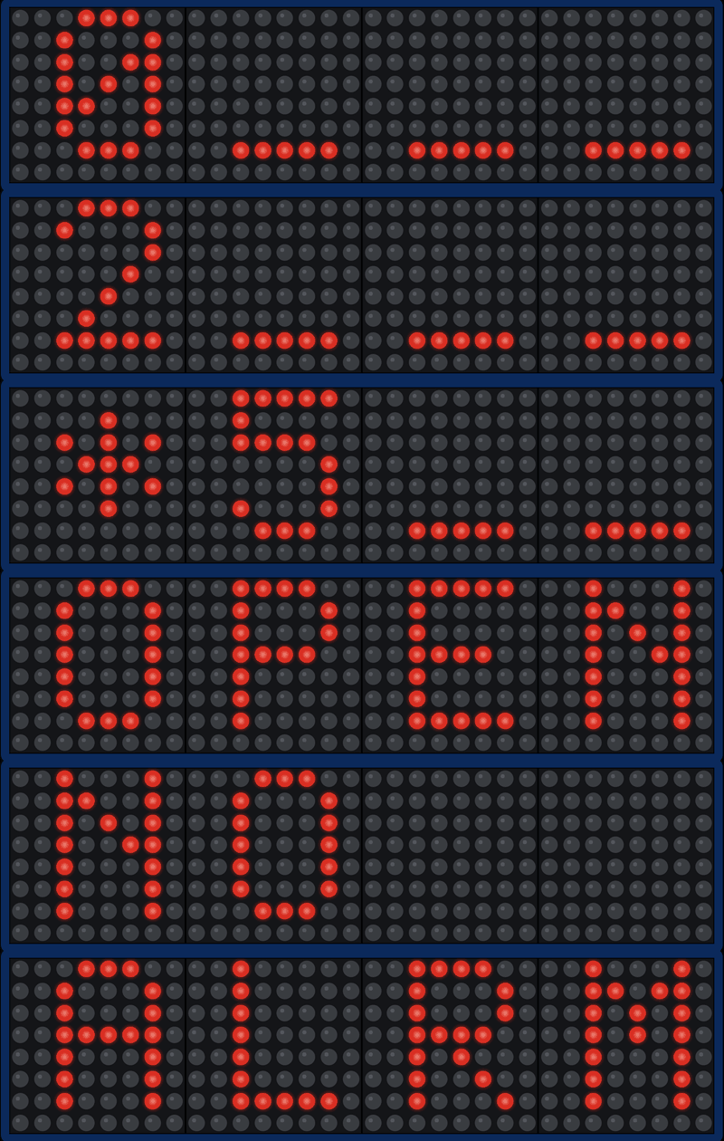
- Shows the code as you go: a 32 x 8 MAX7219 LED matrix, * for each digit entered, the digit you are choosing, _ for the rest.
- Opens a real car door lock: a 0.3-second pulse through a BTS7960 H-bridge drives the actuator's rod to the other end.
- Checks the rod: the actuator's own end switches confirm LOCKED or UNLOCKED, or report JAMMED.
- Locks itself again: 10 seconds after opening.
- Rings an alarm: three wrong codes ring a 12 V electric bell for 5 seconds and ignore the dial for 30 seconds.
- A dashboard: the lock, the dial, the wrong codes and the switches, with UNLOCK and LOCK from a laptop or a phone.
It is a great project for learning how to read an encoder properly, how an H-bridge drives a small motor both ways, and how to switch a 12 V load from a 3.3 V pin. In the simulation, you turn and press the knob in the KY-040's pop-up and watch the rod move in the actuator's pop-up.
Components Used in the Proteus Simulation
All the parts come from our Proteus libraries, each with its own tutorial. The project zip at the end includes every LIB and DLL file.
| Part | Proteus device | Library post | Connection |
|---|---|---|---|
| ESP32 DevKit V1 | ESP32 DEVKIT V1 | ESP32 DevKit V1 Library for Proteus | U1, TEP-WiFi 192.168.1.101 |
| KY-040 rotary encoder | KY040ADVTEP | Rotary Encoder Library for Proteus | ENC1, CLK D32, DT D33, SW D25 |
| MAX7219 4-in-1 LED matrix | MAX7219X4ADVTEP | MAX7219 LED Matrix Library | MX1, DIN D23, CLK D18, CS D5 |
| BTS7960 H-bridge | BTS7960ADVTEP | BTS7960 Motor Driver Library | DRV1, RPWM D26, LPWM D27, EN D14 |
| Car door lock actuator, 12 V | DOORLOCKTEP | Car Door Lock Actuator Library | M1, on the BTS7960; SL D4, SU D13 |
| Electric bell, 12 V | ELECBELLTEP | Electric Bell Library | BELL1, through Q1 |
| IRLZ44N logic-level MOSFET | IRLZ44NTEP | N-MOSFET Library | Q1, gate from D2 |
| 1N5819 Schottky diode | DIODE1N5819TEP | Schottky Diode Library | D1, across the bell |
| Resistors 100 ohm and 10 kohm | RESISTOR4BANDTEP | Resistor Library | R1, R2 at the gate |
| Laptop WiFi Monitor | LAPTOP WIFI MONITOR | Laptop WiFi Monitor | PC1 |
| Mobile WiFi Monitor | MOBILE WIFI MONITOR | Mobile WiFi Monitor | MOB1 |
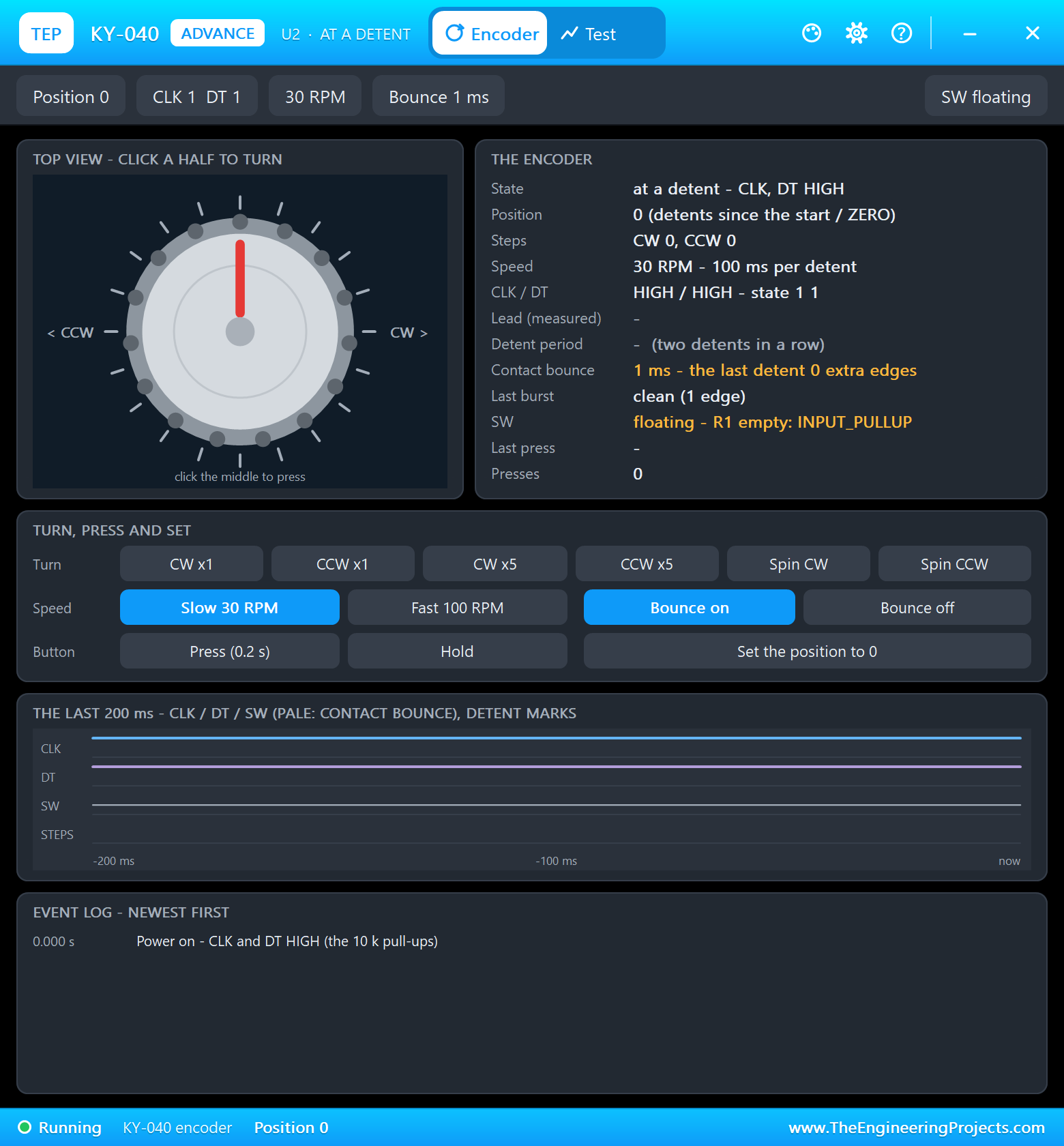
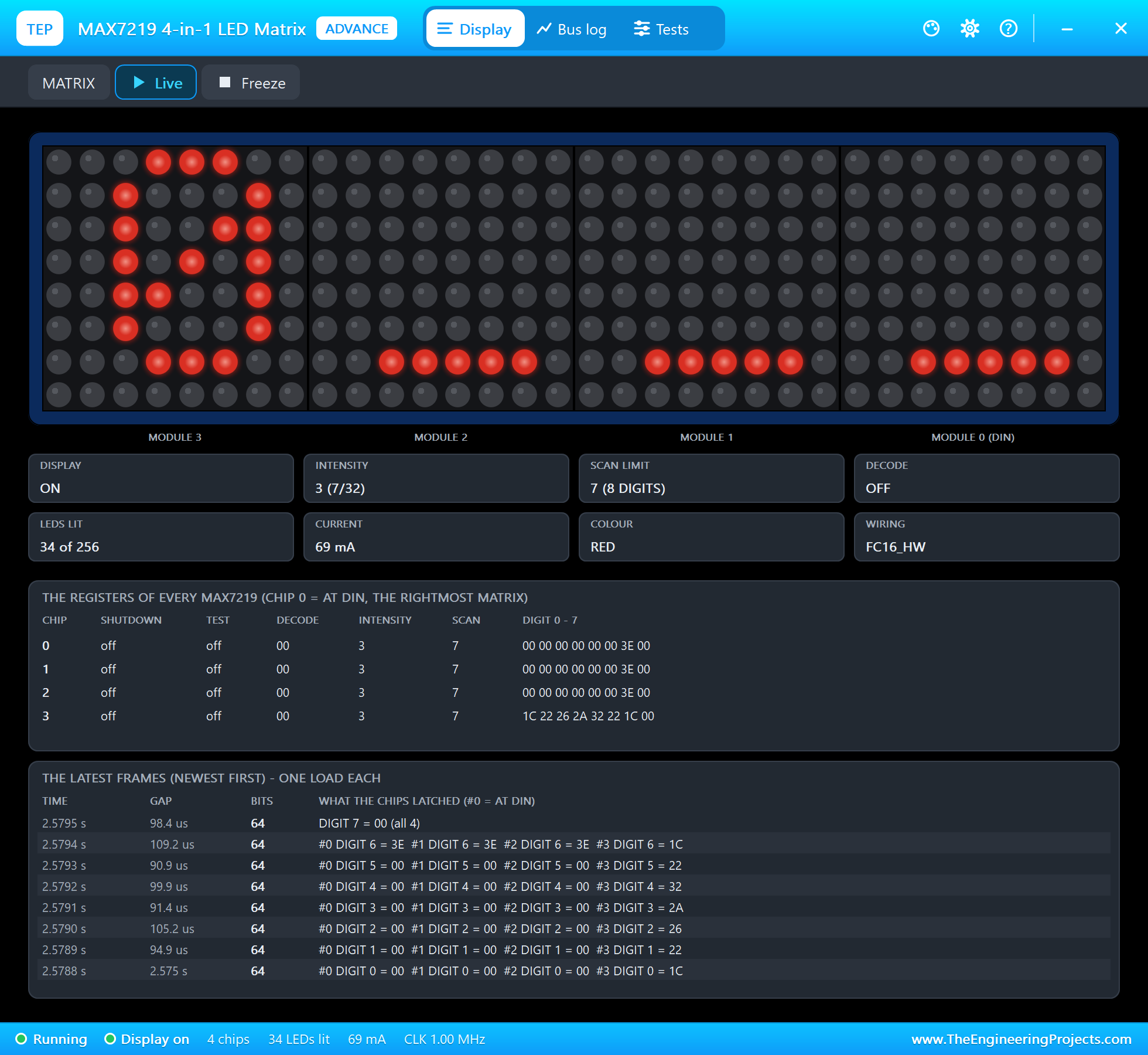
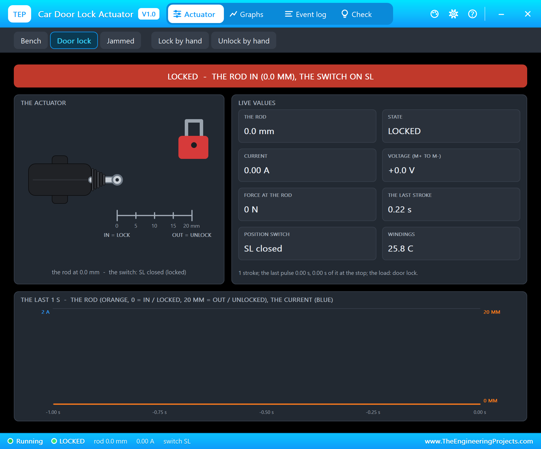
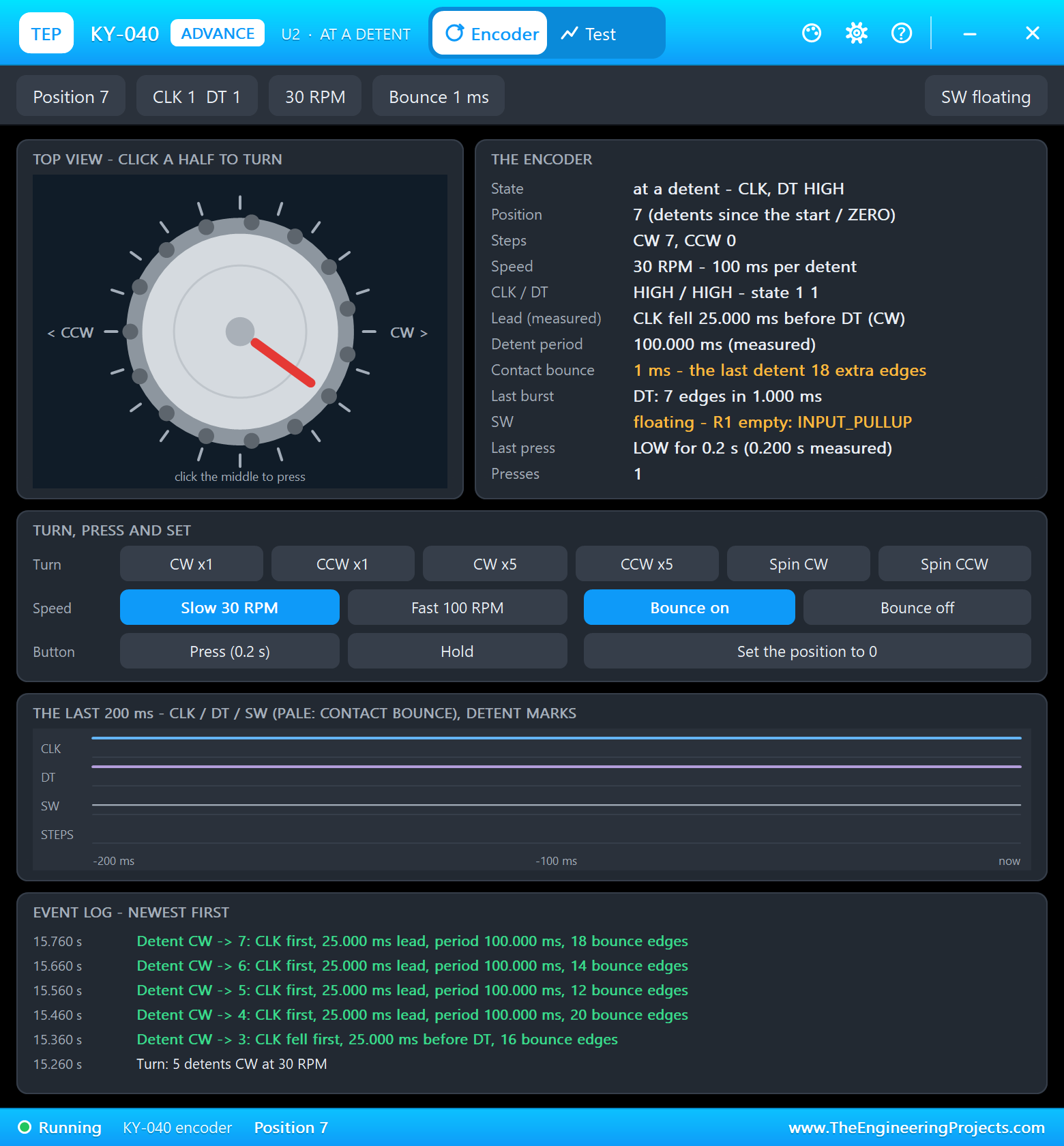
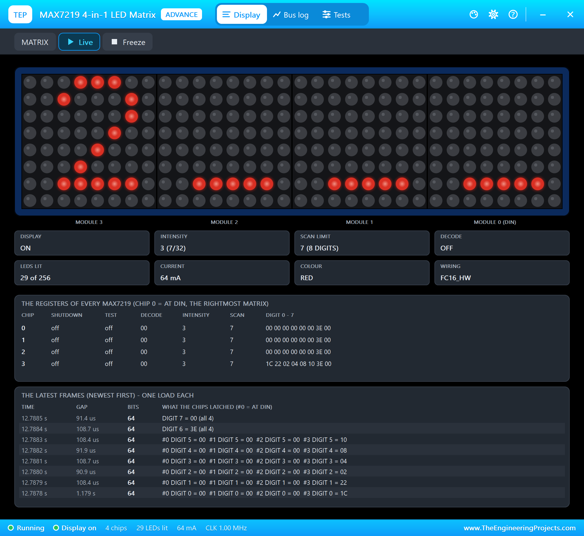
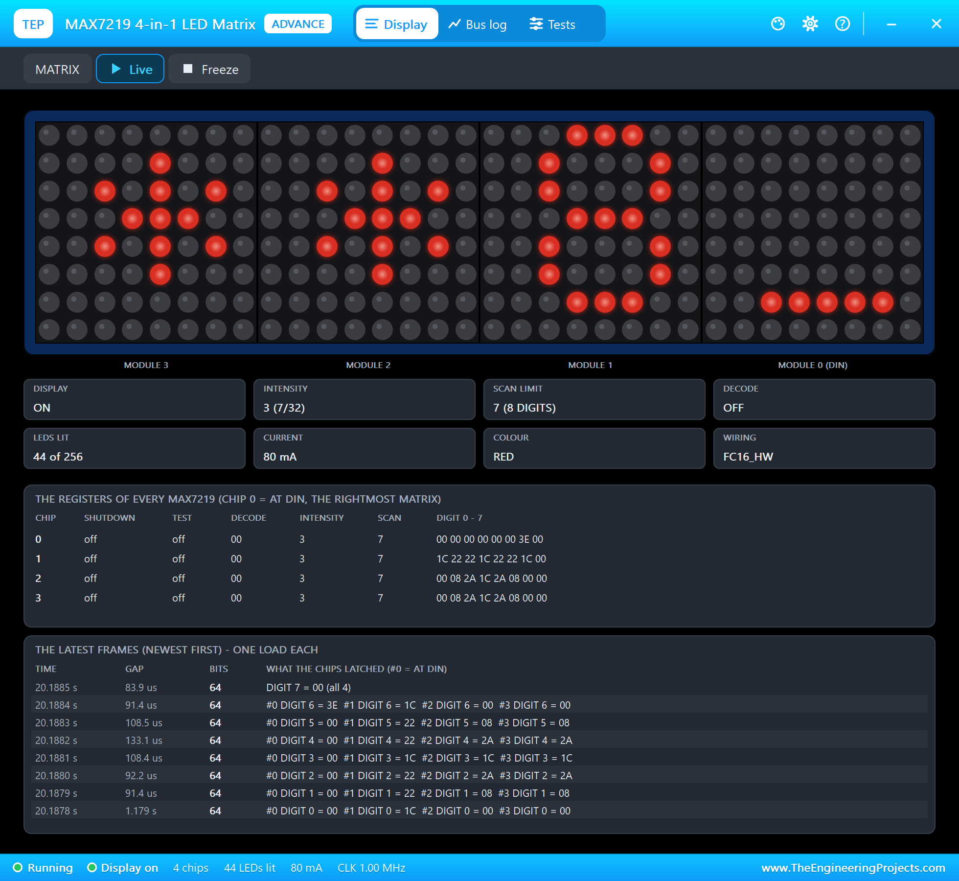
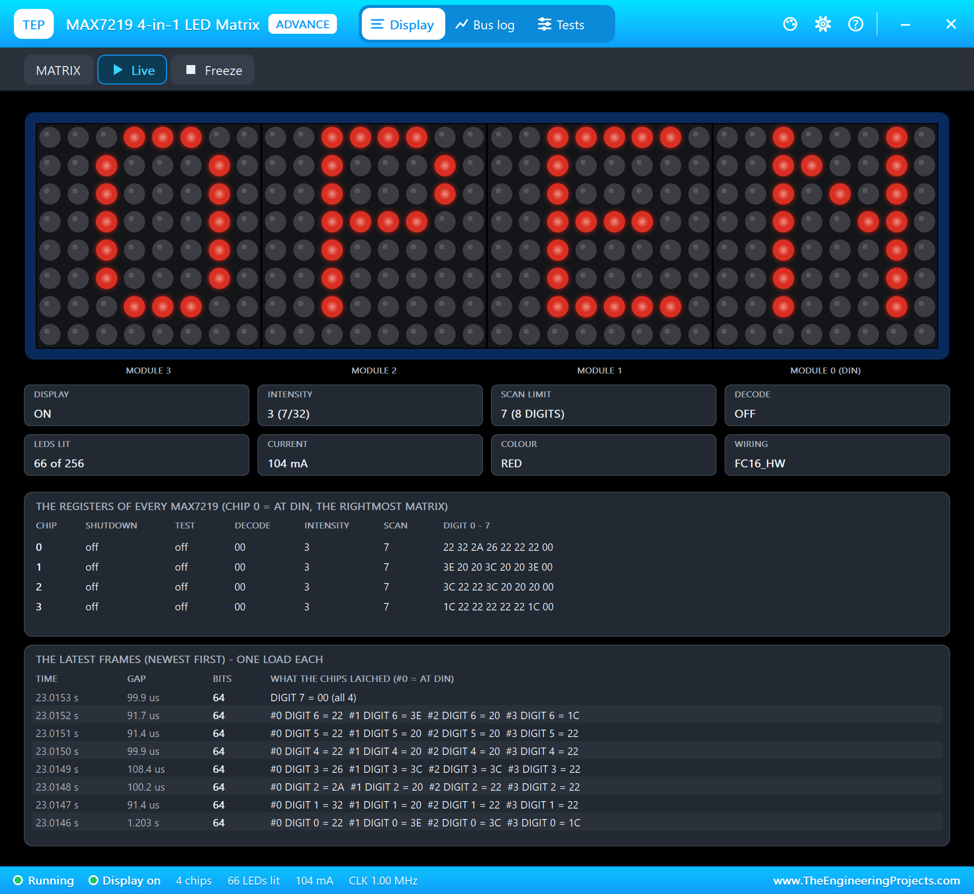
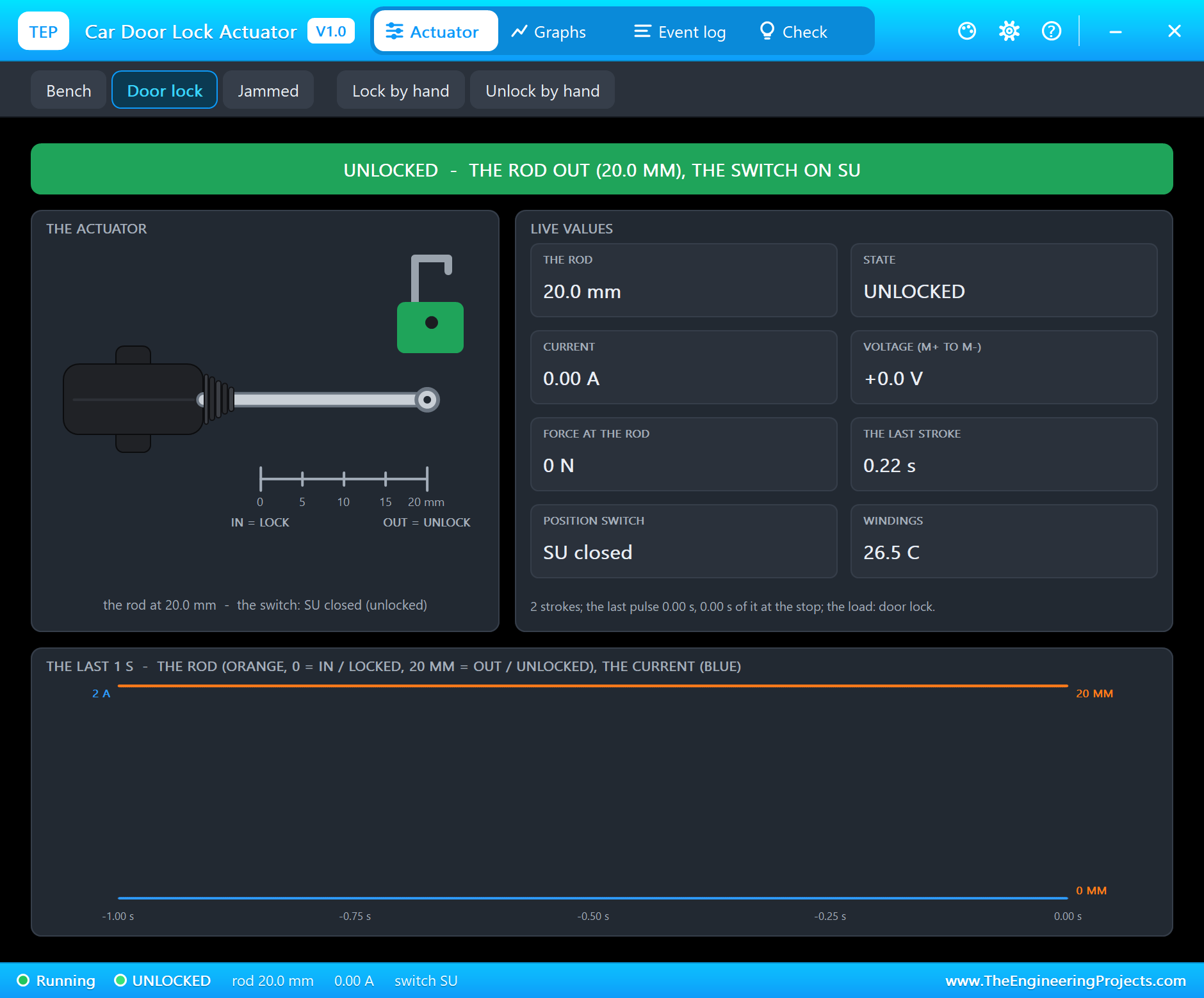
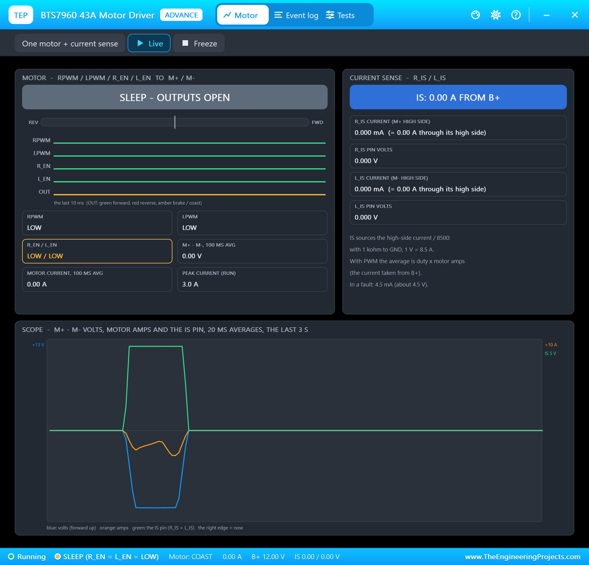
The encoder, the matrix, the driver, the actuator and the bell are models with pop-ups. The KY-040's pop-up turns the knob one click or five, at 30 or 100 r/min, presses it, and shows the CLK, DT and SW levels with every bounce. The matrix's pop-up shows the 32 x 8 LEDs and the MAX7219's registers. The BTS7960's pop-up shows both half-bridges, the output volts and amps. The actuator's pop-up shows the rod, its position, the motor current and the switches. The bell's pop-up shows the hammer, the strikes a second and the current.
Proteus Simulation of the Combination Lock: the Circuit
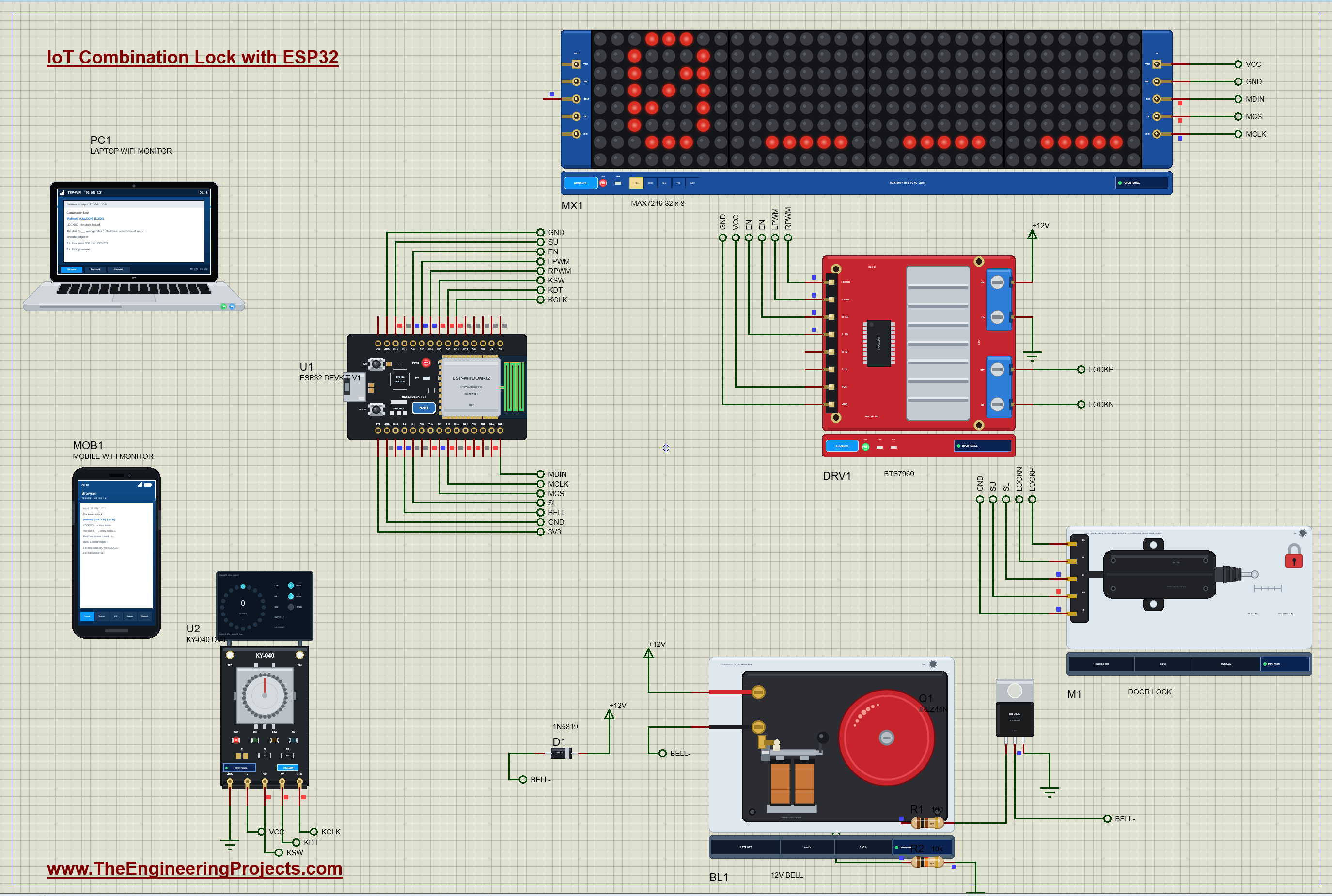
| Part | Pins | ESP32 DevKit V1 |
|---|---|---|
| ENC1 KY-040 | CLK / DT / SW / + / GND | D32 / D33 / D25 (INPUT_PULLUP) / the 5 V rail / GND |
| MX1 MAX7219 | DIN / CLK / CS / VCC / GND | D23 (MOSI) / D18 (SCK) / D5 / the 5 V rail / GND |
| DRV1 BTS7960 | RPWM / LPWM / R_EN, L_EN / VCC | D26 / D27 / D14 / the 5 V rail; B+ +12V, B- GND |
| M1 door lock | M+ / M- / SL / SU / S | the BTS7960's M+ / M- / D4 / D13 / GND |
| BELL1, Q1 | bell + / bell - / Q1 gate | +12V / Q1's drain / D2 through R1 100 ohm (R2 10 k to GND) |
The actuator takes nearly 3 A when its rod reaches an end, far more than any pin, so the BTS7960 switches it; its two PWM inputs pick the direction. The bell takes about half an ampere at 12 V: the IRLZ44N switches it from a 3.3 V pin, R2 keeps it off while the ESP32 starts, and D1 catches the coil's voltage spike every time the bell's own contact breaks. In the simulation, the KY-040 and the MAX7219 take the 5 V rail, which their models want; on a real ESP32 board, run the encoder from 3.3 V.
How the Combination Lock Works
Reading a Rotary Encoder
The KY-040 has two contacts, CLK and DT, that close to ground in turn as the knob rotates; its pull-ups keep them high when open. One click of the knob is one full cycle of four steps: turning clockwise, CLK falls first, then DT, then CLK rises, then DT. Counter-clockwise, DT leads. At rest, at a detent, both are high. So the two contacts form a 2-bit Gray code: 11, 01, 00, 10 and back to 11 clockwise.
The catch is bounce: a mechanical contact does not close cleanly but chatters for about a millisecond. A sketch that counts a click on every falling CLK edge counts the chatter too. The cure is to follow the code: every change of the two contacts is looked up in a table of 16 entries, previous state by new state. A valid neighbour is a quarter step, +1 or -1; a bounce goes forward and back again, +1 then -1, and cancels itself. The sketch counts a click only when the contacts are back at the detent and at least two quarter steps went the same way.
The MAX7219 LED Matrix
The MAX7219 drives an 8 x 8 LED matrix by itself: it multiplexes the rows and holds the picture in eight registers, one a row. It takes 16-bit words over SPI, an address and a data byte. Four of them sit in a chain on the FC-16 module, so one write sends four words while CS is low, the farthest module's word first, and the rising CS latches all four. At start-up the sketch switches off the test mode and the BCD decoding, scans all eight rows, sets the brightness and wakes the chips. Our own 5 x 7 font turns each character into seven row bytes, one character on each module.
The Door Lock and the H-Bridge
A car door lock actuator is a small DC motor with a gear and a rod: power one way and the rod pulls in, the other way and it pushes out. Its stroke takes about 0.22 seconds, and at the end it stalls against its stop. So the sketch never leaves it powered: a 0.3-second pulse through the BTS7960, RPWM to pull the rod in and lock, LPWM to push it out and unlock, then both off. The actuator has two switches of its own, closed at the locked end and at the unlocked end. Twenty milliseconds after the pulse, the sketch reads the one it expects: closed means the rod got there, open means something stopped it, JAMMED.
Switching a 12 V Bell
An electric trembler bell rings on plain DC: its coil pulls the hammer, which opens the bell's own contact, which releases the hammer, and so on, about 28 strikes a second. The ESP32 only has to switch the 12 V on and off, and a logic-level MOSFET does it: the IRLZ44N turns fully on with 3.3 V on its gate. Every time the bell's contact breaks the coil's current, the coil tries to keep it flowing with a voltage spike; the 1N5819 across the bell gives that current a path and protects the MOSFET.
The Arduino Code Explained
The whole sketch is included in the download. It needs no extra library: it reads the encoder, drives the matrix through the ESP32's SPI and drives the lock itself, and uses the ESP32's WiFi and WebServer libraries. At the top are the code and the timings:
const char CODE[] = "2580";                               // the combination
const unsigned long PULSE_MS = 300;                       // the actuator's stroke takes about 0.22 s
The Encoder
const int8_t QUARTER[16] = {0, -1, 1, 0, 1, 0, 0, -1, -1, 0, 0, 1, 0, 1, -1, 0}; // [previous << 2 | now] quarters += QUARTER[ab << 2 | now]; // a bounce goes back and forth: +1 -1 if (quarters >= 2) clicks++; else if (quarters <= -2) clicks--;The Matrix
for (int chip = 3; chip >= 0; chip--) { SPI.transfer(reg); SPI.transfer(data[chip]); } mxAll(0x0F, 0); mxAll(0x09, 0); mxAll(0x0B, 7); mxAll(0x0A, 3); mxAll(0x0C, 1); // no test, no decode, 8 rows, intensity 3, onThe Lock
  analogWrite(unlockIt ? LPWM : RPWM, 255);                // M+ positive (RPWM) pulls the rod in = locked; LPWM pushes it out
  delay(PULSE_MS);
bool atEnd = digitalRead(unlockIt ? SW_UNLOCKED : SW_LOCKED) == LOW; if (wrong >= MAX_WRONG) { setState(ALARM); digitalWrite(BELL, HIGH); show("ALRM"); event("ALARM: the bell rings 5 s, the dial locked 30 s"); }The timers live in loop(), measured from the moment the state last changed: a wrong code shows NO for 1.5 seconds, an open door locks itself after 10 seconds, the bell stops after 5 seconds and the dial is free again after 30:
  unsigned long in = millis() - stateAt;
  if (state == WRONG && in > 1500) { setState(ENTER); showEntry(); }
  if (state == OPEN && in > RELOCK_MS) lockDoor("10 s open - locking again");
  if (state == ALARM && in > ALARM_MS && digitalRead(BELL)) { digitalWrite(BELL, LOW); event("the bell stops"); }
  if (state == ALARM && in > LOCKOUT_MS) { wrong = 0; setState(ENTER); showEntry(); event("the dial free again"); }
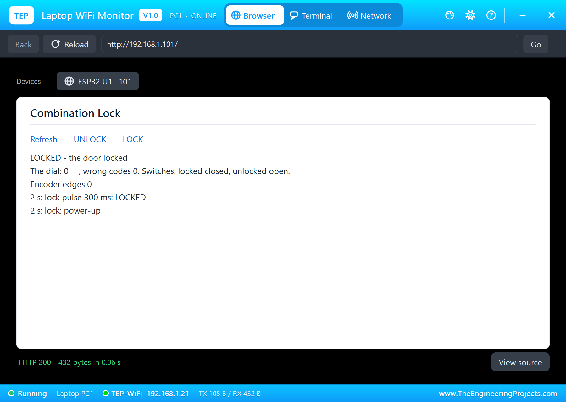
The pages are / (the dashboard), /unlock and /lock (not during an alarm) and /data (JSON). The dashboard puts its three links first and stays short, because the WiFi Monitors show one screen of a page.
How to Run the Proteus Simulation
- Download the project zip below and install the library files (the steps are under the download button).
- Open ESP32-Combination-Lock.pdsprj from the Proteus Simulation folder. Keep the HEX and the DLL files next to it.
- Press Play. The lock goes to its locked end and the matrix shows 0___.
- In the KY-040's pop-up (ENC1), turn the knob and press it for each digit: 2 (two clicks), 5 (five clicks), 8 (two clicks back) and 0.
- Open the Laptop WiFi Monitor (PC1) or the Mobile WiFi Monitor (MOB1), press Go, and try UNLOCK and LOCK.
- Enter three wrong codes to hear the bell.
Simulation Results: the Combination Lock in Proteus
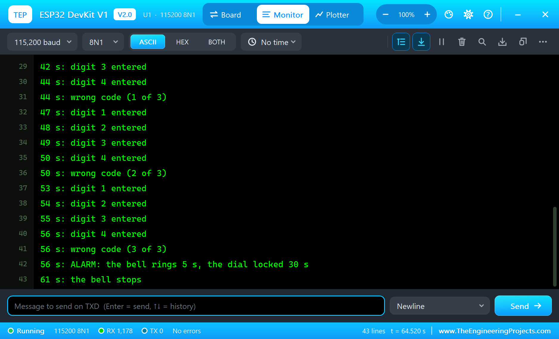
Here is the run that made the screenshots of this tutorial, 64.65 seconds of simulation from Play to the end. The times are the sketch's own, the seconds since the ESP32 started, as it printed them on its serial monitor.
Power-Up: the Lock Finds Its End
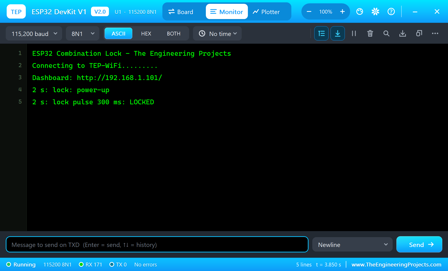
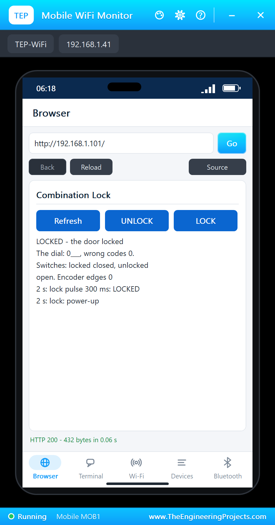
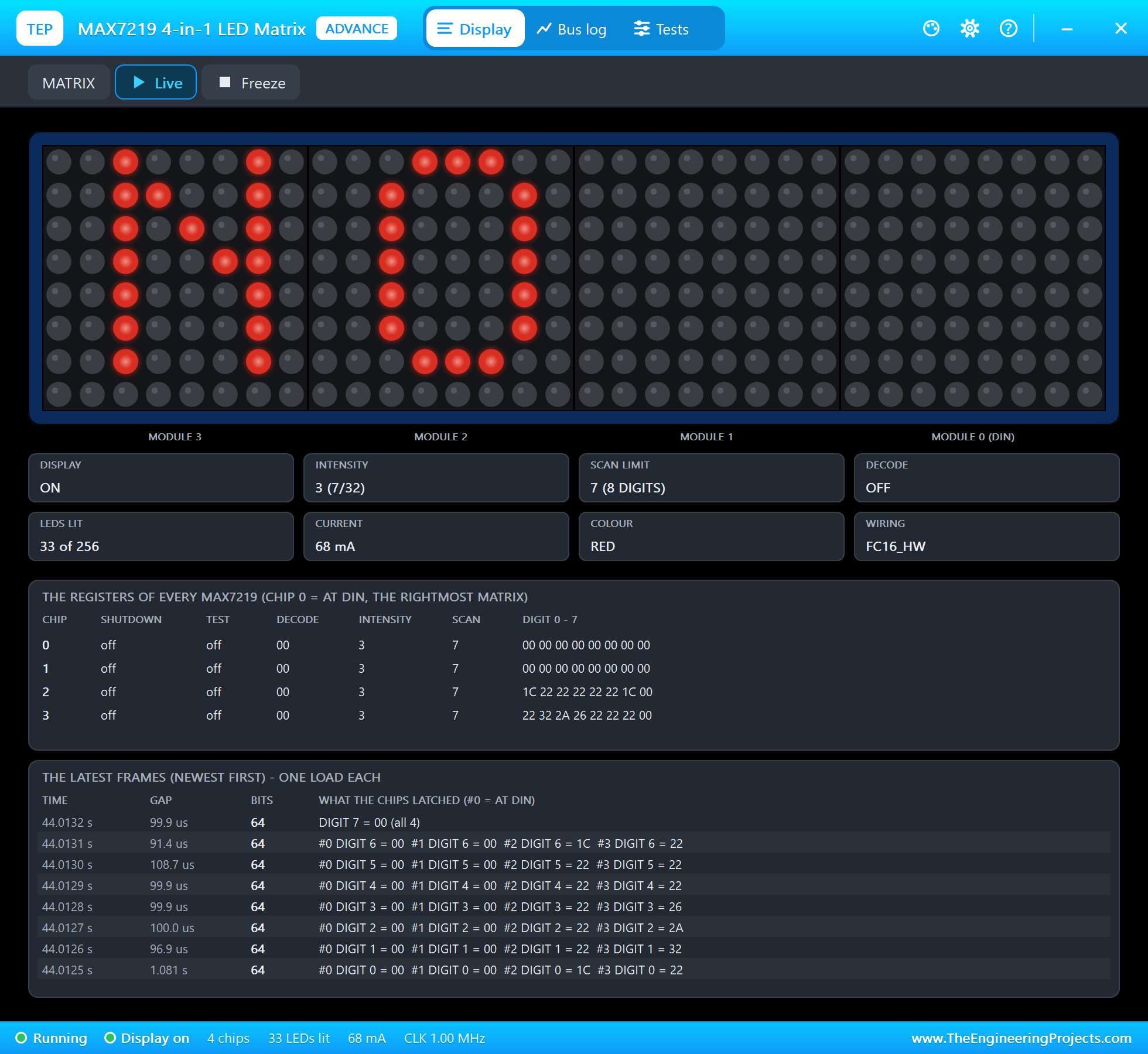
The ESP32 joins TEP-WiFi, prints its dashboard address, and at 2 seconds gives the actuator a locking pulse: the sketch does not trust the rod to be where it was left, so it drives it to the locked end and checks switch SL. The serial monitor shows "lock pulse 300 ms: LOCKED", and the matrix shows 0___, the first digit ready at 0.
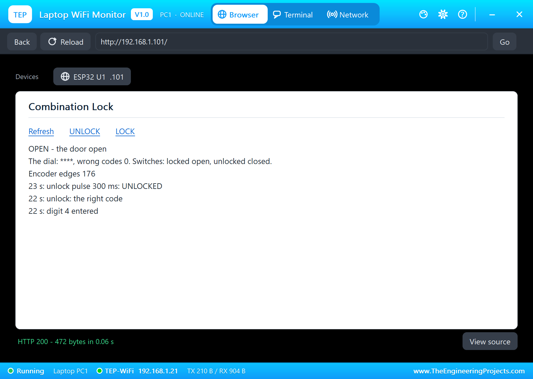
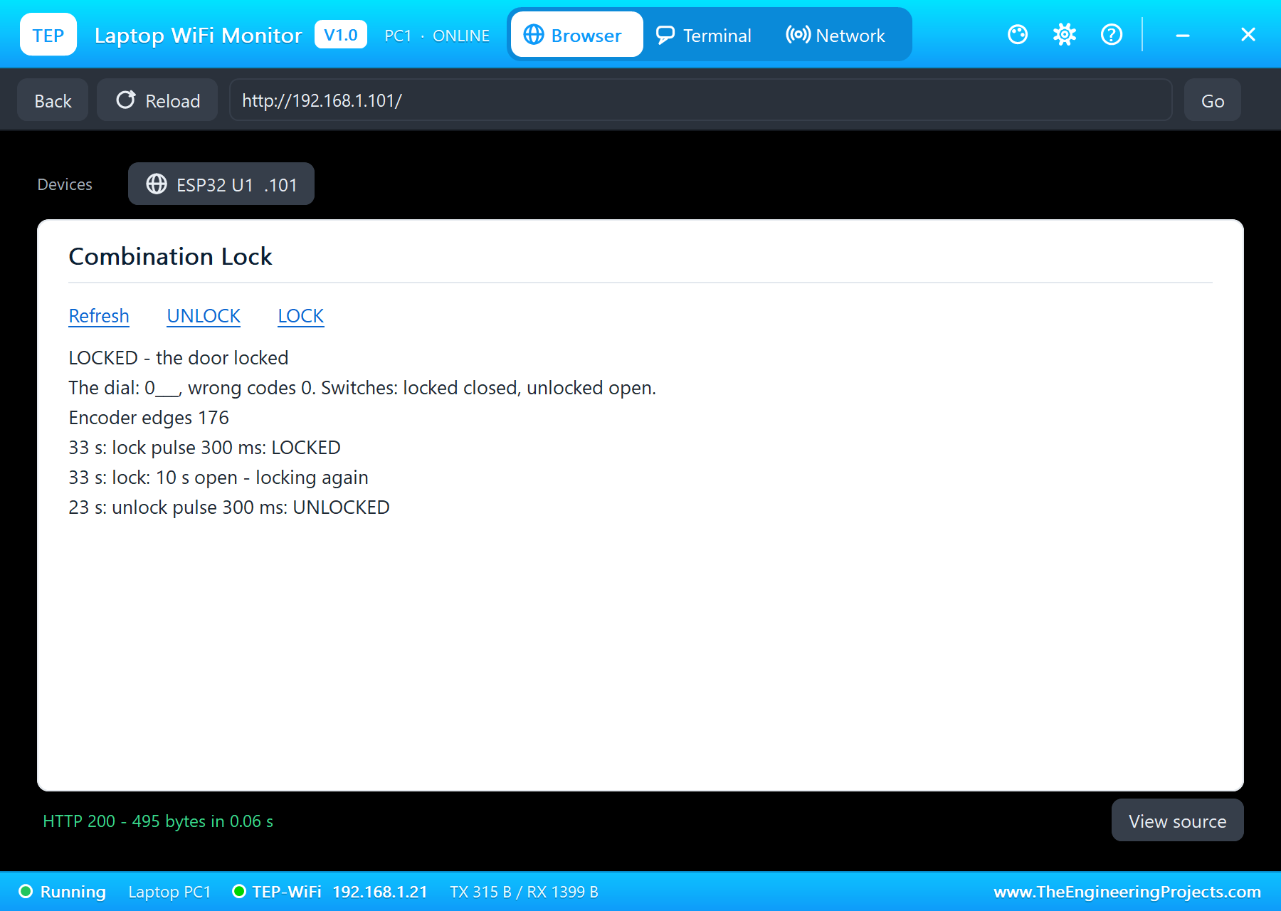
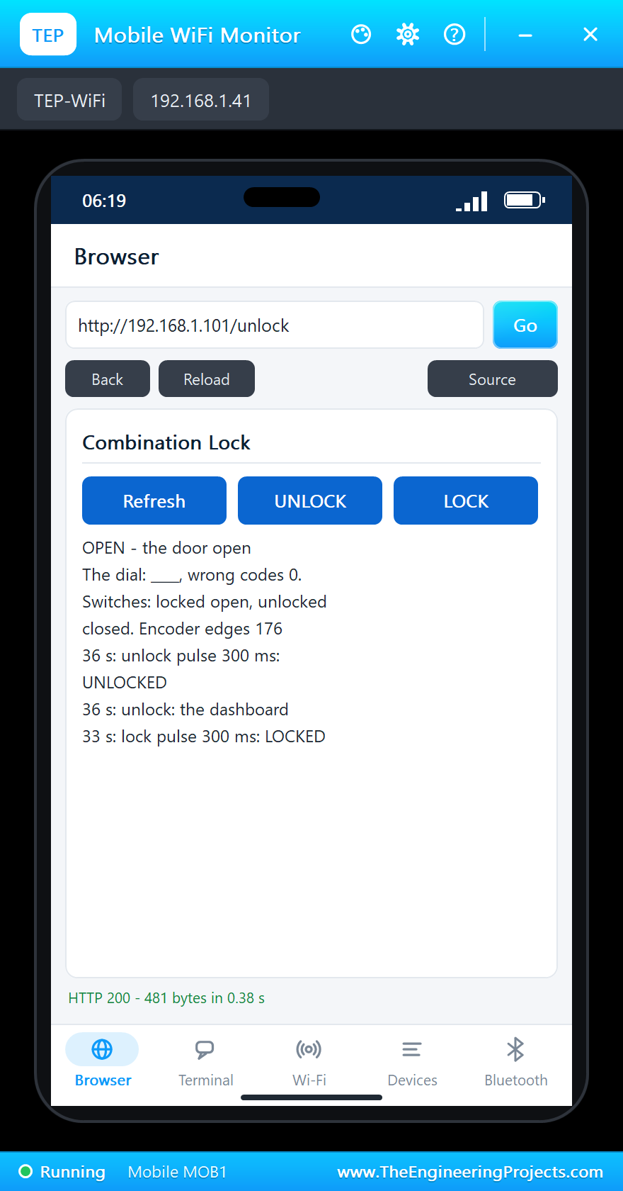
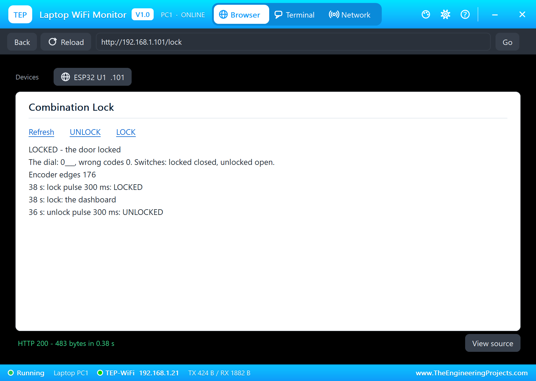
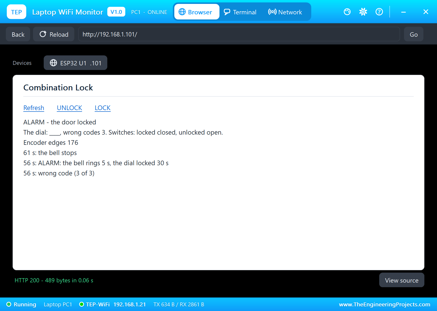
Both WiFi Monitors open the dashboard at 192.168.1.101. Its three links, Refresh, UNLOCK and LOCK, come first, then the state, the dial and the switches, and the last events, newest first.
Entering the Right Code: 2-5-8-0
Two clicks clockwise make the first digit 2, and a press at 14 seconds enters it. The second digit takes five clicks at once, the pop-up's CW x5 at 30 r/min, one click every 100 milliseconds. The KY-040's event log shows what the decoder had to deal with: every click came with 12 to 20 bounce edges, CLK leading DT by 25 milliseconds. The sketch still counted exactly five, and the monitor shows "dial +1 - digit 2 is 1" up to 5. That is the quarter-step table at work: each bounce went forward and back and cancelled itself.
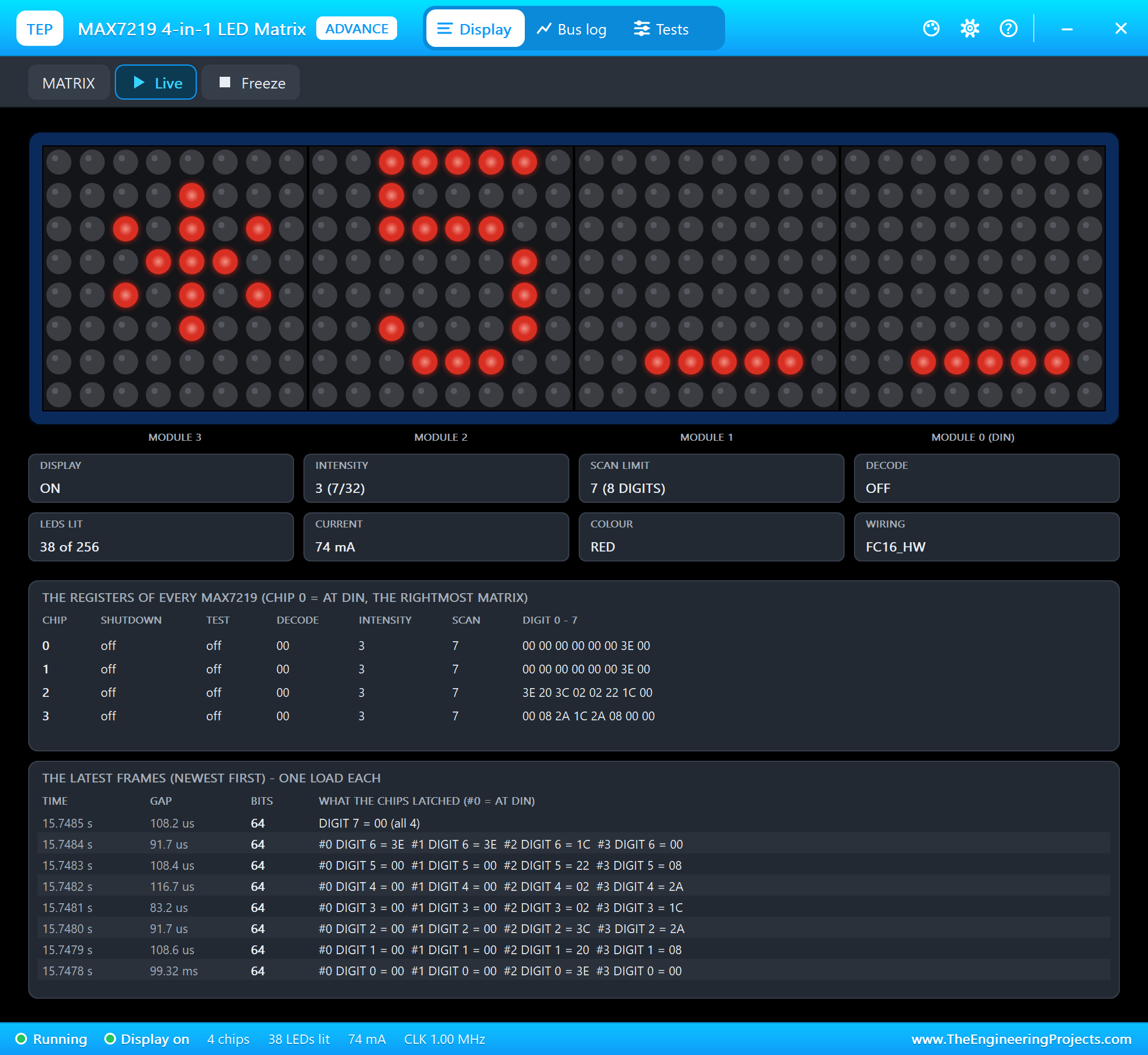
For the third digit, two clicks counter-clockwise go from 0 back through 9 to 8: the digits wrap around, as on a real safe dial. A press at 21 seconds enters it, and the fourth press at 22 seconds enters 0 without a turn. The code is right, and the sketch prints "unlock: the right code".
At 23 seconds the unlock pulse ends: "unlock pulse 300 ms: UNLOCKED". The actuator's pop-up shows the rod out at 20.0 mm after a stroke of 0.22 seconds, and switch SU closed, so the sketch knows the rod really got there. The BTS7960's scope shows the pulse: the output at the 12 V supply for 0.3 seconds, the current dipping as the motor ran and climbing to its peak of 3.0 A as the rod stalled at its stop, and then both half-bridges off, the outputs open.
Ten seconds later, at 33 seconds, the sketch locks again by itself: "10 s open - locking again" and a locking pulse. A door that is left unlocked by mistake does not stay that way.
Remote Unlock and Lock from the Dashboard
At 36 seconds, UNLOCK on the phone opens the door: "unlock: the dashboard" and the same 300 ms pulse. At 38 seconds, LOCK on the laptop locks it again. Both go through the same pulse() function as the dial, so the end switches check a remote command too.
Three Wrong Codes Ring the Alarm
Now someone tries 0000, four presses without turning the knob. At 44 seconds the sketch prints "wrong code (1 of 3)" and the matrix shows NO for a moment before going back to 0___. The second try ends at 50 seconds, the same way.
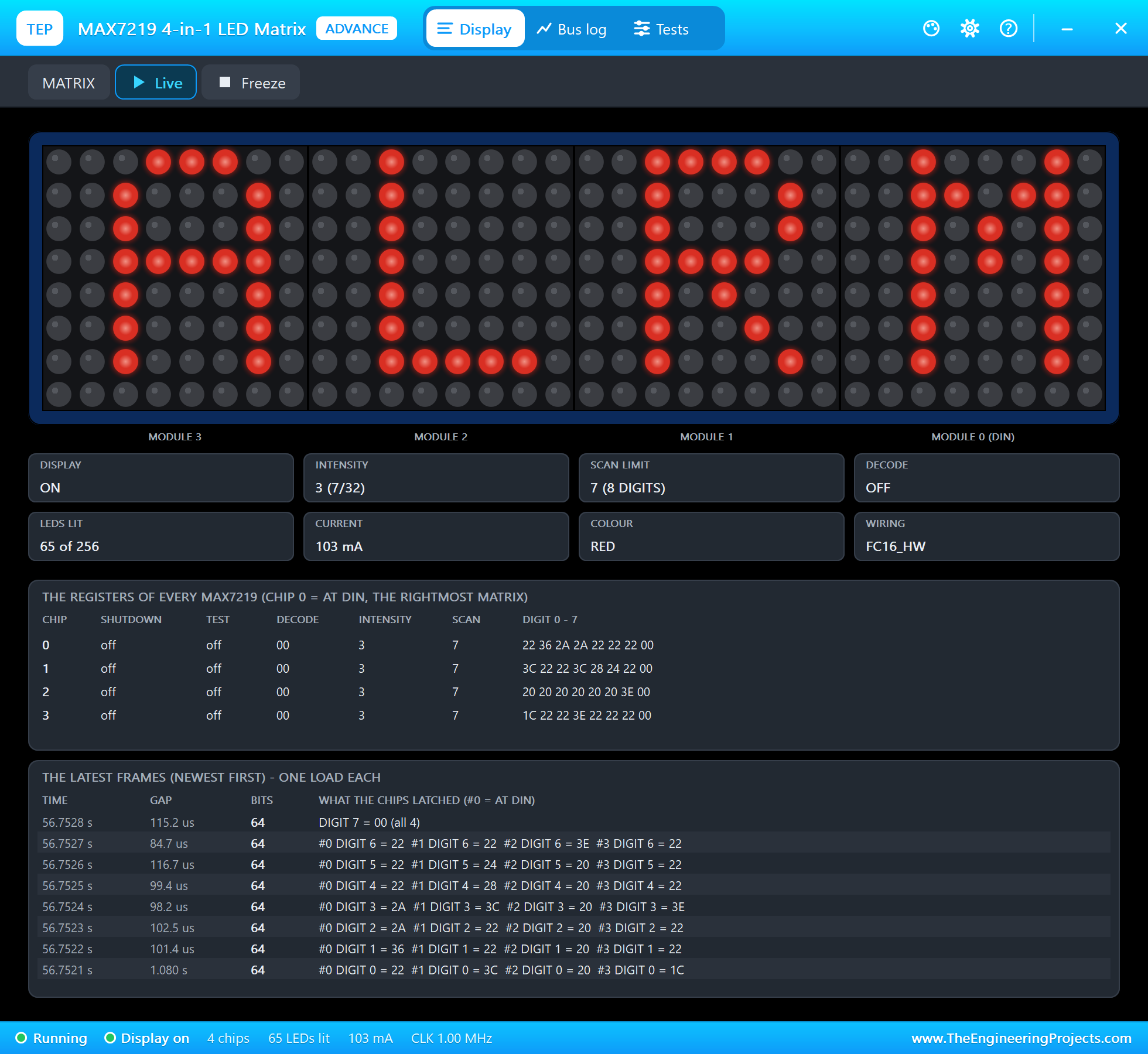
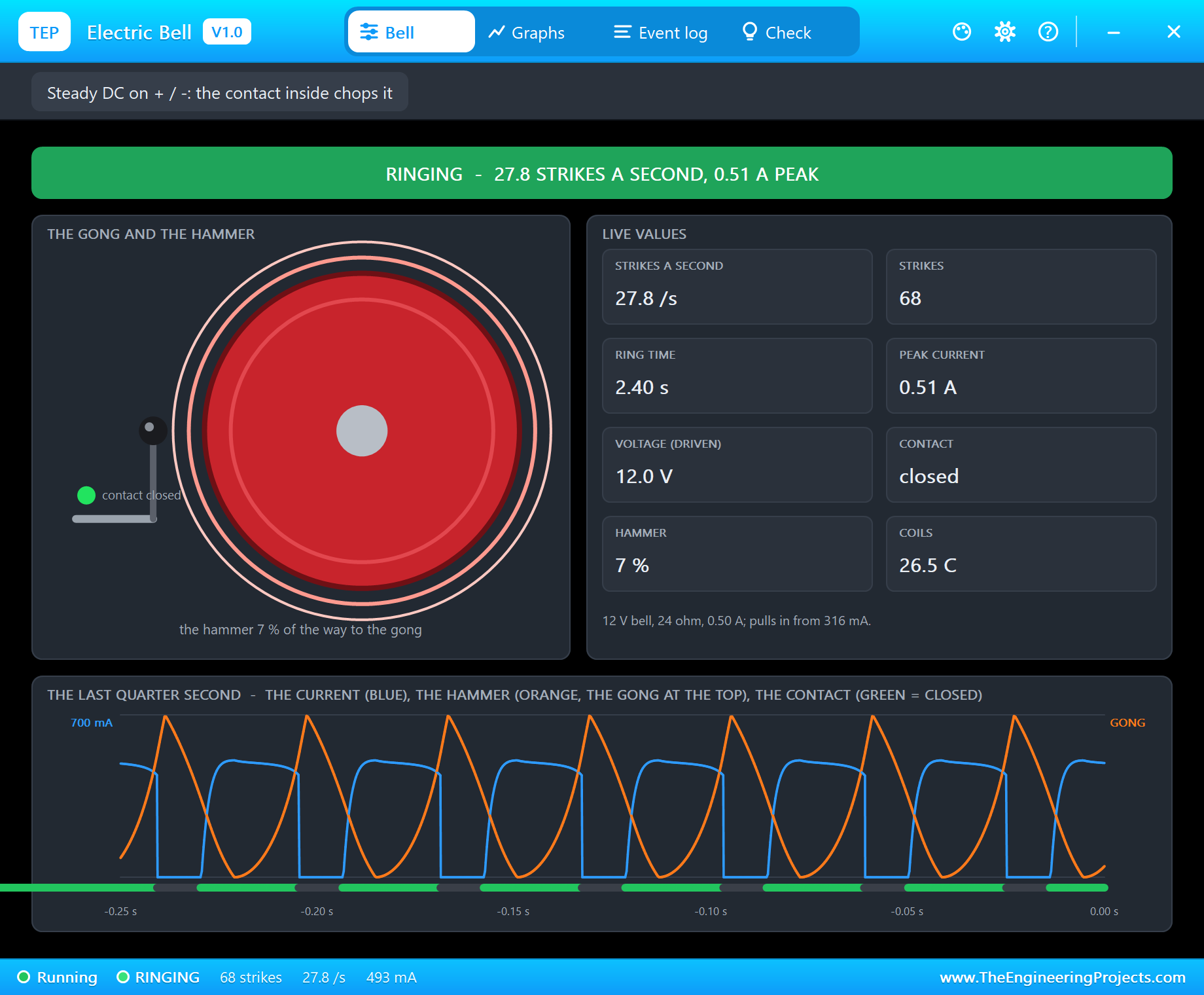
The third wrong code at 56 seconds starts the alarm: "ALARM: the bell rings 5 s, the dial locked 30 s". The matrix shows ALRM, D2 goes high, and the IRLZ44N switches the bell on. The bell's pop-up shows the trembler at work: 27.8 strikes a second, a peak current of 0.51 A from the 12 V supply, the hammer swinging between the coil and the gong. At 61 seconds, "the bell stops": 139 strikes in five seconds.
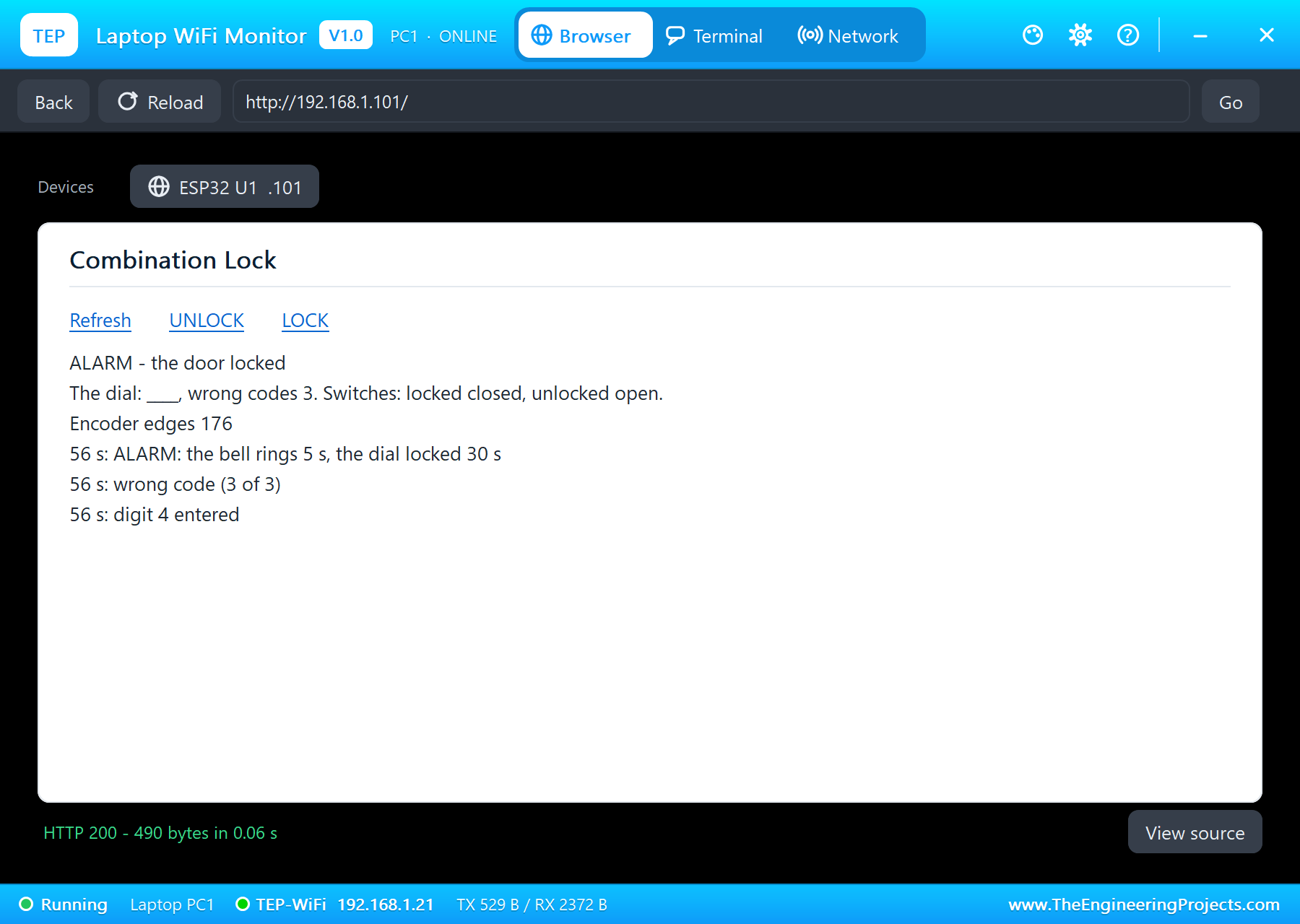
During the 30-second lockout, the dial does nothing and neither does the dashboard's UNLOCK: an intruder cannot just try again, and a stolen phone cannot open the door while the alarm rings. The dashboard at the end of the run still shows ALARM, wrong codes 3, the locked switch closed, and the encoder's 176 edges, bounces included, that the sketch read during the run.
The Numbers of the Run
| What | Result |
|---|---|
| Power-up | LOCKED at 2 s, switch SL closed |
| Right code 2-5-8-0 | entered at 14, 17, 21 and 22 s; UNLOCKED at 23 s |
| Stroke | 20.0 mm in 0.22 s; the 300 ms pulse peaked at 3.0 A |
| Relock | LOCKED again at 33 s, 10 s after opening |
| Dashboard | UNLOCK at 36 s from the phone, LOCK at 38 s from the laptop |
| Wrong codes | 44, 50 and 56 s; ALARM at 56 s |
| Bell | 27.8 strikes a second, 0.51 A peak, 139 strikes in 5 s |
| Actuator | 5 strokes in the run, windings 28.3 C |
| Matrix | intensity 3: 38 of 256 LEDs on for *5__, about 74 mA |
| Encoder | 12 to 20 bounce edges a click, every click counted once |
| Simulation | 64.65 s of simulation |
Download the Project Files
Click the button below to download IoT-Combination-Lock-ESP32-Proteus-Simulation-v1.0.zip (about 5.2 MB, without the source code of the models):
IoT Combination Lock with ESP32 - Proteus Simulation V1.0- Proteus Simulation: ESP32-Combination-Lock.pdsprj, the compiled HEX file and copies of the models.
- Arduino Code: ESP32_Combination_Lock.ino, the complete sketch.
- Proteus Library Files: the LIB files of the ESP32 DevKit V1, the KY-040, the MAX7219 matrix, the BTS7960, the door lock, the bell, the MOSFET, the diode, the resistor and the two WiFi Monitors.
- Proteus Model Files: the DLL models.
- README.txt: the installation steps, the properties, the test results and the links to every library post.
No Proteus yet? Read How to Download and Install Proteus 7 and 8. New to libraries? Follow How to Install a New Library in Proteus.
How to Install the Project Files
- Close Proteus and extract the whole zip file, for example to your Desktop.
- Copy the files from Proteus Library Files into the LIBRARY folder of Proteus.
- Copy the files from Proteus Model Files into the MODELS folder.
- Start Proteus and open the project from the Proteus Simulation folder.
Changing the Code
Open the sketch in the Arduino IDE with the ESP32 boards installed, compile it, export the compiled binary and set the board's PROGRAM property to the new file. The code, the pulse length and the alarm times are at the top. The same sketch runs on a real ESP32 DevKit V1. For our other ESP32 lock, with a touch keypad and a solenoid, see the IoT Smart Door Lock with ESP32.
Ideas to Extend the Project
- Let the owner change the code from the dashboard, and keep it in the ESP32's flash.
- Count down the 30-second lockout on the matrix.
- Scroll text across the matrix: WELCOME when the door opens.
- Send a message to the owner's phone when the alarm rings.
- Add a door sensor and lock only when the door is closed.
- Use the encoder's speed: a fast spin jumps five digits at a time.
From Simulation to Real Hardware
- Power the actuator properly: nearly 3 A at the end of the stroke; give the BTS7960 a 12 V supply that can deliver it, with a fuse.
- Keep the pulse short: a stalled actuator heats up; 0.3 seconds is enough for a 0.22-second stroke.
- Power the encoder from 3.3 V: its outputs then suit the ESP32's pins.
- Drive the MAX7219 at 5 V: its input threshold is 3.5 V at 5 V supply; most modules accept the ESP32's 3.3 V, but a 74HCT buffer makes it certain.
- Do not rely on it for real security: this is a teaching project; a real lock needs a battery backup and tamper protection.
Troubleshooting
- One click counts twice, or not at all: the bounce; keep the quarter-step decoder.
- The matrix shows mirrored text: another module type; the FC-16 is used here.
- JAMMED after every pulse: no 12 V on the BTS7960, the enables low, or the actuator's switches not wired.
- The bell does not ring: Q1's gate or the bell's + supply.
- The dashboard's UNLOCK does nothing: an alarm is running; wait 30 seconds.
Limitations of the Simulation
- The door is the actuator's DOOR load; there is no real door, handle or latch.
- The knob is turned from the KY-040's pop-up, one click or five at a time.
- The network is simulated: the dashboard travels between the ESP32 and the two monitors inside Proteus; the times in this tutorial are simulation time.
- ESP32 is made by Espressif, the MAX7219 by Analog Devices (Maxim), the BTS7960 and the IRLZ44N by Infineon. This project is not made or endorsed by them or by Labcenter.
So, that was all about the IoT Combination Lock with ESP32 - Proteus Simulation. I hope it helps you build your own lock: a rotary encoder read properly in spite of its bounce, an LED matrix driven over SPI with our own font, a door lock actuator pulsed through an H-bridge and checked by its own switches, and a 12 V bell switched by a MOSFET, all tested in a simulation before you wire a single part. More IoT projects with the ESP32 and the Raspberry Pi 5 are coming in this series. If you have any questions, ask in the comments and I will help you out. Till the next tutorial, take care and have fun!

Comments
0