


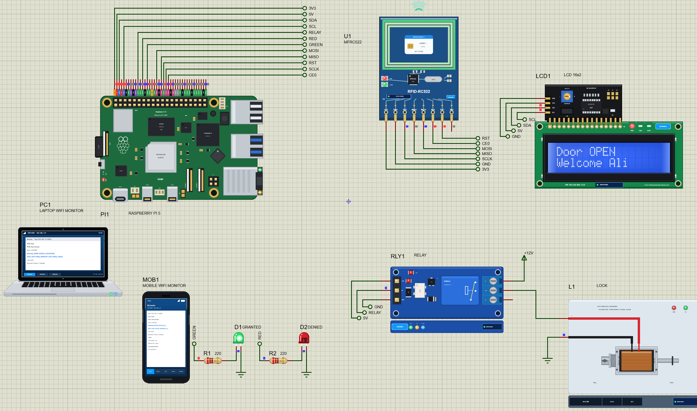
Raspberry Pi 5 RFID Door Access - Proteus Simulation


Hello friends, I hope you all are doing great. Today, I am going to share the Raspberry Pi 5 RFID Door Access - Proteus Simulation, the fourth project of our IoT Projects series. If you have searched for a Proteus simulation of an RFID door lock with a Raspberry Pi, here is a complete one. A Raspberry Pi 5 reads RFID cards with an MFRC522 reader, opens a solenoid lock through a relay for the cards it knows, shows each event on an I2C LCD, and keeps a log on a web page. From a phone or a laptop you can read the log, enrol a new card, lock the door down, or open it remotely.
Access control is a classic IoT project: offices, labs, hostels and homes all use cards to open doors and need to know who came in and when. In this tutorial, we will go through the circuit, learn how the MFRC522 finds a card and reads its unique ID, see how the Raspberry Pi drives an LCD over I2C, walk through the Python program, and then run the simulation: a known card, a refused visitor who is then enrolled, a lockdown and a remote opening. At the end, you can download the project with the program, every library file and the Python runtime the Pi needs.
NOTICE: Our team has put a lot of effort into this project: the circuit, the code and every part in the simulation are our own work, and you get them all free. Your feedback is the fuel that keeps us going, so please tell us what you think in the comments below. And if our free projects help you, you can buy us a coffee. So, let's get started with the Raspberry Pi 5 RFID Door Access - Proteus Simulation:
What Does This RFID Door Access System Do?
The system is a small version of the card readers you see at office doors. Every card has a unique ID number; the Raspberry Pi keeps a list of the IDs that may enter and decides in a fraction of a second.
- Read: an MFRC522 RFID reader on the Pi's SPI bus wakes any card held near it and reads its 4-byte UID.
- Decide: a known card opens the door for 3 seconds; an unknown card is refused; during a lockdown every card is refused.
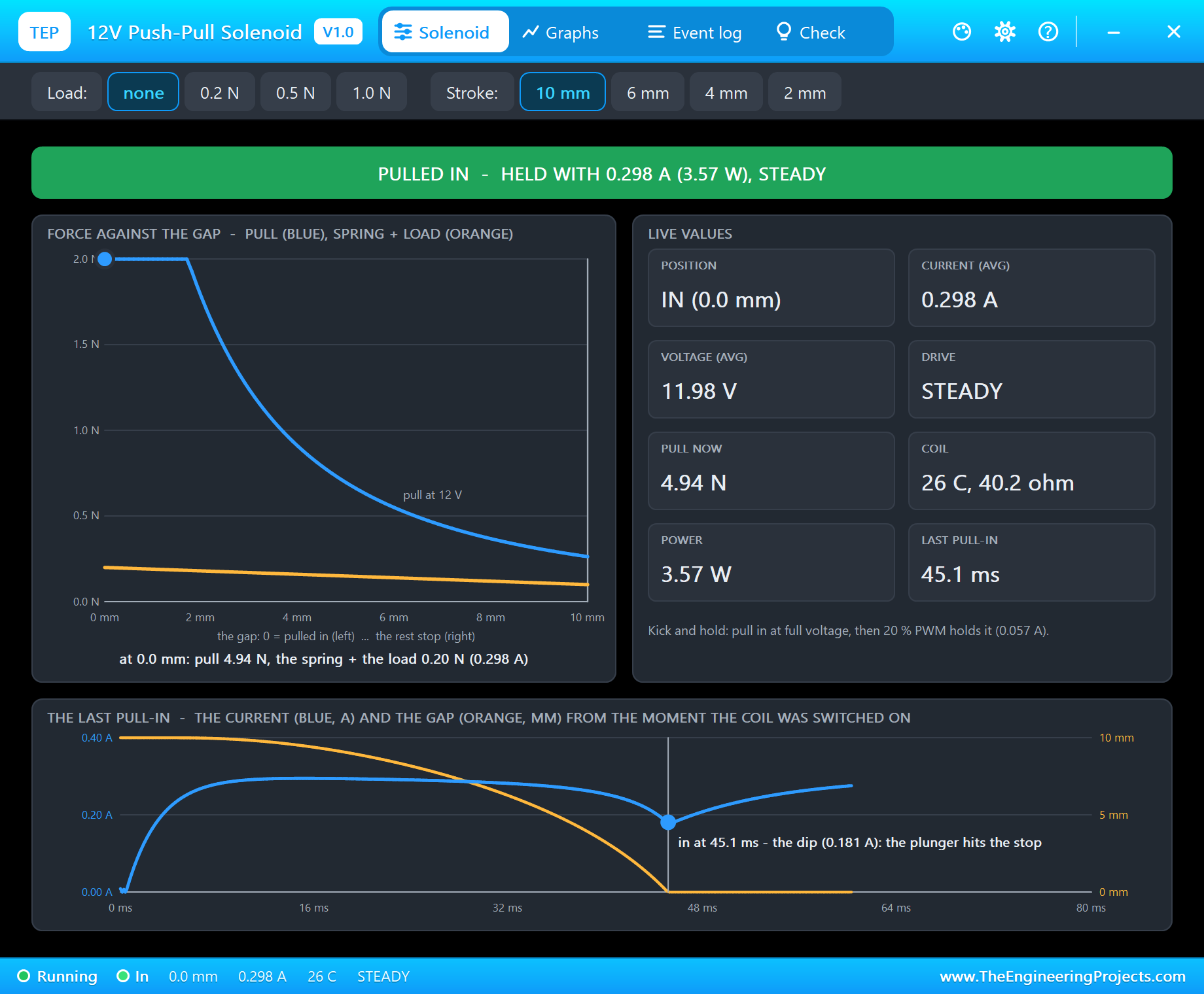
- Act: a relay powers a 12 V push-pull solenoid, which pulls the bolt back while the door is open.
- Show: a 16x2 I2C LCD says "Door locked", "Door OPEN - Welcome Ali" or "ACCESS DENIED"; a green or a red LED lights.
- Log: every event goes into a log with the time, the card and the result, shown on the web page and in the terminal.
- Manage: from the page, ADD LAST CARD enrols the last refused card, REMOVE LAST CARD deletes a user, LOCKDOWN refuses everyone, and OPEN DOOR opens it remotely.
It is a good project for students of embedded systems and IoT, and a practical start for a real access-control system. Running it as a simulation lets you test every rule, every card and every web action before you mount anything on a door.
Components Used in the Proteus Simulation
All the parts come from our Proteus libraries, each with its own tutorial. The project zip at the end includes every LIB and DLL file and the Python runtime, so there is nothing else to download.
| Part | Proteus device | Library post | Connection |
|---|---|---|---|
| Raspberry Pi 5 | RASPBERRY PI 5 | Raspberry Pi 5 Library for Proteus | PI1, Ethernet 192.168.1.51, runs door_access.py |
| MFRC522 RFID reader | MFRC522ADVTEP | MFRC522 RFID Library for Proteus | SPI0: SDA GPIO8, SCK GPIO11, MOSI GPIO10, MISO GPIO9, RST GPIO25 |
| I2C LCD 16x2 | I2CLCD16X2BLUEADVTEP | I2C LCD 16x2 Library for Proteus | SDA GPIO2, SCL GPIO3, address 0x27 |
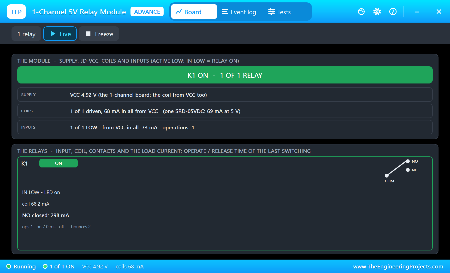
| 1-channel relay module | RELAY1ADVTEP | Relay Module Library for Proteus | IN GPIO17 (active LOW) |
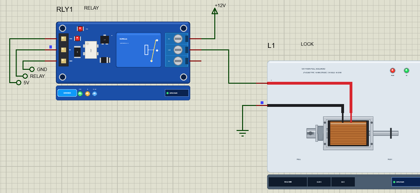
| 12 V push-pull solenoid (the lock) | SOLENOID12VTEP | 12V Push-Pull Solenoid Library for Proteus | on the relay's COM, +12 V on NO |
| Green and red LEDs | LED5MMGREENTEP, LED5MMREDTEP | 5mm LED Library | GPIO22 (granted), GPIO27 (denied) |
| Two 220 ohm resistors | RESISTOR4BANDTEP | Resistor Library | in series with the LEDs |
| Laptop WiFi Monitor | LAPTOP WIFI MONITOR | Laptop WiFi Monitor | PC1, opens the dashboard |
| Mobile WiFi Monitor | MOBILE WIFI MONITOR | Mobile WiFi Monitor | MOB1, opens the dashboard |
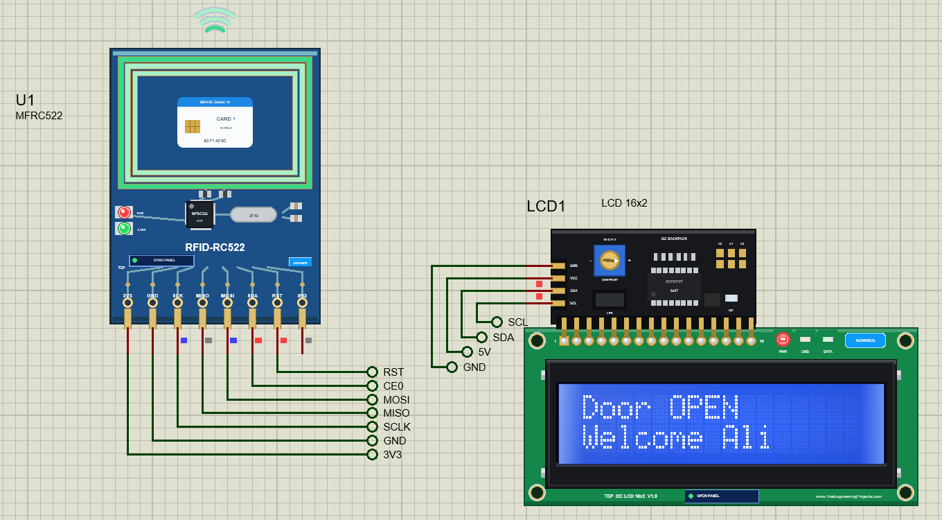
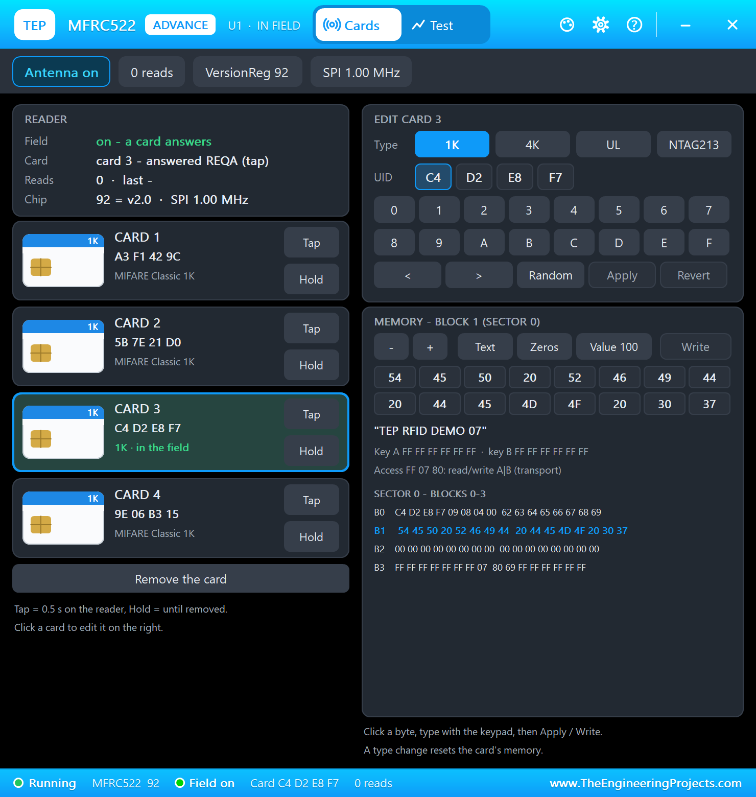
The MFRC522 model is a full register-level model of the real chip, and its cards answer like real ISO 14443-3A cards. Its pop-up holds four cards: you press Tap to hold a card on the reader for half a second, or Hold to leave it there. We gave the cards the UIDs A3F1429C (Ali), 5B7E21D0 (Sara), C4D2E8F7 (a visitor) and 9E06B315 (a spare) through the reader's UID1 to UID4 properties.
Proteus Simulation of the RFID Door Access: the Circuit
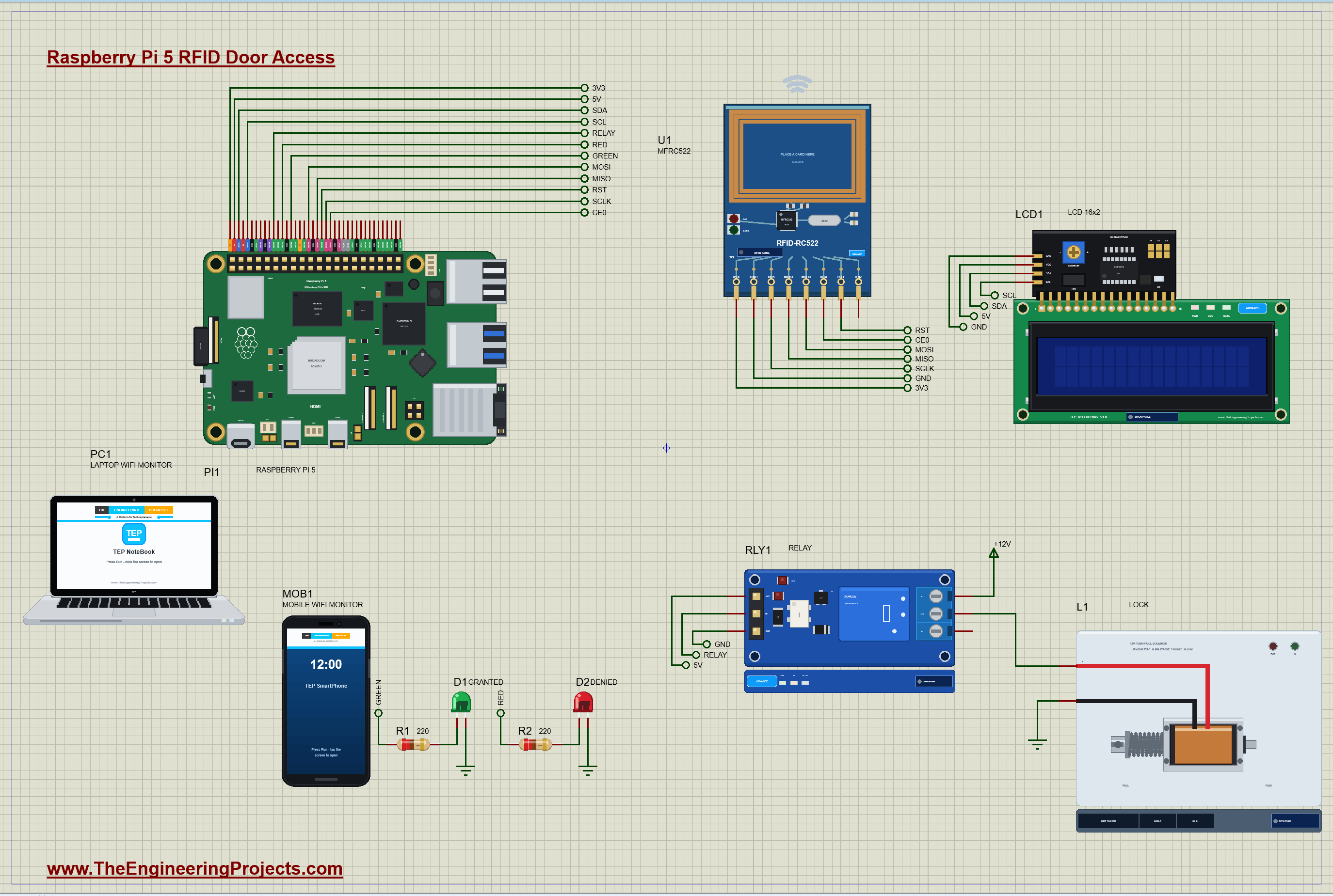
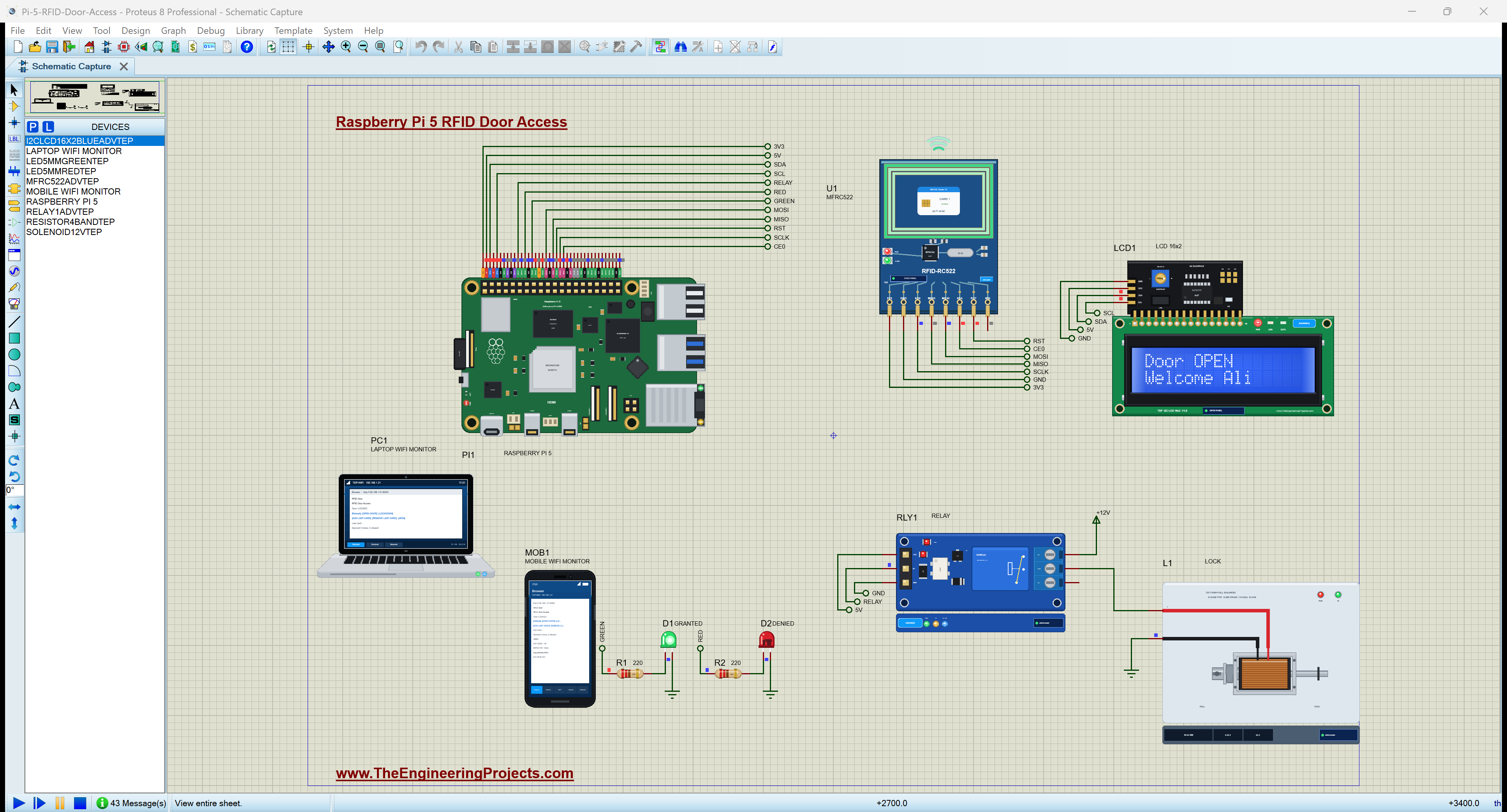
The Pi's 40-pin header is wired with net labels: each header pin goes up and to the right to a label, and the same label sits next to the pin it connects to. The laptop and the phone reach the Pi over the network, so they have no wires.
| Pi header pin | Net | Connected to | Why |
|---|---|---|---|
| 1 (3V3) | 3V3 | MFRC522 3V3 | the reader is a 3.3 V part |
| 2 (5V) | 5V | LCD VCC, relay VCC | the 5 V parts |
| 3, 5 (GPIO2, GPIO3) | SDA, SCL | the LCD's backpack | I2C1, the Pi's main I2C bus |
| 19, 21, 23, 24 | MOSI, MISO, SCLK, CE0 | MFRC522 MOSI, MISO, SCK, SDA | SPI0 with chip select 0 |
| 22 (GPIO25) | RST | MFRC522 RST | the reader's reset |
| 11 (GPIO17) | RELAY | relay IN | the lock |
| 15, 13 (GPIO22, GPIO27) | GREEN, RED | the LEDs through 220 ohm | granted / denied |
The Lock
The lock is a 12 V push-pull solenoid: when its coil is powered, the plunger is pulled in, which pulls a bolt out of the strike plate and lets the door open. The relay's contacts switch it: +12 V goes to NO and the solenoid hangs on COM, so the coil is powered only while the relay is on. The relay module's input is active LOW, so the program sets GPIO17 HIGH at power-up and keeps the door locked until it decides otherwise.
The Reader's SDA Pin
The MFRC522 board can talk SPI, I2C or UART, which is why its pins carry a mixed set of names. In SPI mode, its SDA pin is the chip select, so it goes to the Pi's CE0 (GPIO8). Its IRQ pin is not needed here; the program polls the reader instead.
How the RFID Door Access Works
How the MFRC522 Finds a Card
RFID cards have no battery. The reader's antenna sends out a 13.56 MHz field, and a card held near it takes its power from that field. The reader then talks to the card in short frames. To find a card, it sends REQA, a 7-bit "request" command; any card in the field answers with a two-byte reply. Next comes anticollision: the reader sends 0x93 0x20, and the card answers with its 4-byte UID plus a check byte, the BCC, which is the XOR of the four UID bytes. If the BCC matches, the UID is good.
All of that goes through the MFRC522's registers. Every SPI transfer is an address byte followed by data: bits 6 to 1 of the address byte are the register number, and bit 7 says read or write. The program writes the bytes to send into the FIFO register, starts a Transceive command, waits for the chip's interrupt flags, and reads the answer back from the FIFO.
RFID Cards and Their Memory
The cards in this project are MIFARE Classic 1K cards, the most common type in offices and public transport. Apart from the UID, which is written at the factory and cannot be changed, a 1K card holds 1024 bytes of memory in 16 sectors of four blocks. Each sector has two keys and access bits that decide who may read or write it. Our program uses only the UID, which is enough for a door: the UID is read without any key, in a few milliseconds. The memory is useful when the card itself must carry information, such as a name, a balance or an expiry date.
The UID is printed on the reader's pop-up as four bytes, for example A3 F1 42 9C. The program joins them into the text A3F1429C and uses that as the key of its users dictionary, so adding a user is just adding one line. The MFRC522 model also offers 4K, Ultralight and NTAG213 cards; their UIDs are longer (seven bytes) and need a second anticollision step, which you can add as an exercise.
Driving the LCD over I2C
The 16x2 LCD has the classic HD44780 controller, which needs at least six wires in 4-bit mode. The small PCF8574 backpack turns that into two I2C wires: each byte written to the PCF8574 sets its eight outputs, which are wired to the LCD's RS, RW, E, the backlight and the four data lines D4 to D7. To send a nibble, the program writes it once with E high and once with E low; the falling edge of E makes the LCD take it. Two nibbles make a byte, a command or a character.
The Door's Rules
The program reads the reader ten times a second. A card counts once until it has been away for a second, so holding a card does not open the door again and again. A known card opens the door for three seconds; an unknown card lights the red LED for a second and is remembered as the "last unknown card", so you can enrol it from the page. In lockdown, every card is refused, but the page's OPEN DOOR still works: an operator can always let someone in.
The Python Code Explained
The whole program, door_access.py, is included in the download. It uses spidev for the reader, lgpio (the GPIO library of the Pi 5's RP1 chip) for the LCD's I2C, the relay and the LEDs, and the standard http.server for the page. The most common MFRC522 Python libraries depend on RPi.GPIO, which does not support the Pi 5, so our program talks to the reader's registers itself. At the top are the pins and the users:
RST_PIN, RELAY_PIN, GREEN_PIN, RED_PIN = 25, 17, 22, 27        # BCM numbers
LCD_ADDR = 0x27
UNLOCK_S = 3.0                                                 # the door stays open this long
PORT = 8000
users = {'A3F1429C': 'Ali', '5B7E21D0': 'Sara'}               # card UID -> name
Talking to the MFRC522
A register write and a register read are each one SPI transfer. After a soft reset, the program sets the chip's timer to about 25 ms (so a missing card is noticed quickly), selects 100 % ASK modulation as the cards expect, and switches the antenna on:
    def write(self, reg, val):
        self.spi.xfer2([(reg << 1) & 0x7E, val])

    def read(self, reg):
        return self.spi.xfer2([((reg << 1) & 0x7E) | 0x80, 0])[1]
self.write(self.T_MODE, 0x8D); self.write(self.T_PRESCALER, 0x3E) # the timer: about 25 ms
self.write(self.T_RELOAD_H, 0); self.write(self.T_RELOAD_L, 30)
self.write(self.TX_ASK, 0x40); self.write(self.MODE, 0x3D) # 100 % ASK, CRC preset 6363h
self.write(self.TX_CONTROL, self.read(self.TX_CONTROL) | 0x03) # the antenna onReading a card's UID is two Transceive commands: REQA, which must be answered with exactly 16 bits, and anticollision, which must return five bytes whose last byte is the XOR of the first four:
    def read_uid(self):
        """REQA (7 bits) wakes a card in the field; anticollision returns its UID + BCC. The UID as hex, or None."""
        r = self.transceive([0x26], 7)
        if not r or r[1] != 16: return None
        r = self.transceive([0x93, 0x20])
        if not r or len(r[0]) != 5: return None
        uid = r[0]
        if uid[0] ^ uid[1] ^ uid[2] ^ uid[3] != uid[4]: return None   # the check byte
        return ''.join('%02X' % b for b in uid[:4])
The LCD Driver
The LCD class is just as short. A nibble is two I2C writes, E high then E low, with the backlight bit always set; a byte is two nibbles, and RS chooses between a command and a character:
    def nibble(self, n, rs):
        b = n | 0x08 | rs                                      # (0x08 = the backlight)
        lgpio.i2c_write_byte(self.h, b | 0x04)                 # E high ...
        lgpio.i2c_write_byte(self.h, b)                        # ... and low: the LCD takes the nibble

    def byte(self, v, rs):
        self.nibble(v & 0xF0, rs); self.nibble((v << 4) & 0xF0, rs)
Opening the Door
Opening the door switches the relay on (LOW), lights the green LED, notes the time when the door must lock again, and updates the LCD. The reader's loop locks the door again when that time has passed:
def unlock(why):
    global open_until
    lgpio.gpio_write(chip, RELAY_PIN, 0)                       # the relay on: the solenoid pulls the bolt
    lgpio.gpio_write(chip, GREEN_PIN, 1)
    open_until = time.monotonic() + UNLOCK_S
The Reader Loop
This is the decision. A card is handled only when it is new or has been away for more than a second. Its UID is looked up in the users; lockdown, a known card and an unknown card each lead to their own event, LCD message and LED:
        uid = reader.read_uid()
        t = time.monotonic()
        if uid and (uid != last_uid or t - last_seen > 1.0):
            with lock:
                name = users.get(uid, '')
                down = state['lockdown']
                state['last'], state['lastName'] = uid, name
                if not name: state['lastUnknown'] = uid
            if down:
                event(uid, name or 'unknown', 'DENIED (lockdown)'); deny('Lockdown')
            elif name:
                event(uid, name, 'GRANTED'); unlock('Welcome ' + name)
            else:
                event(uid, 'unknown', 'DENIED'); deny('Card ' + uid)
The Web Page
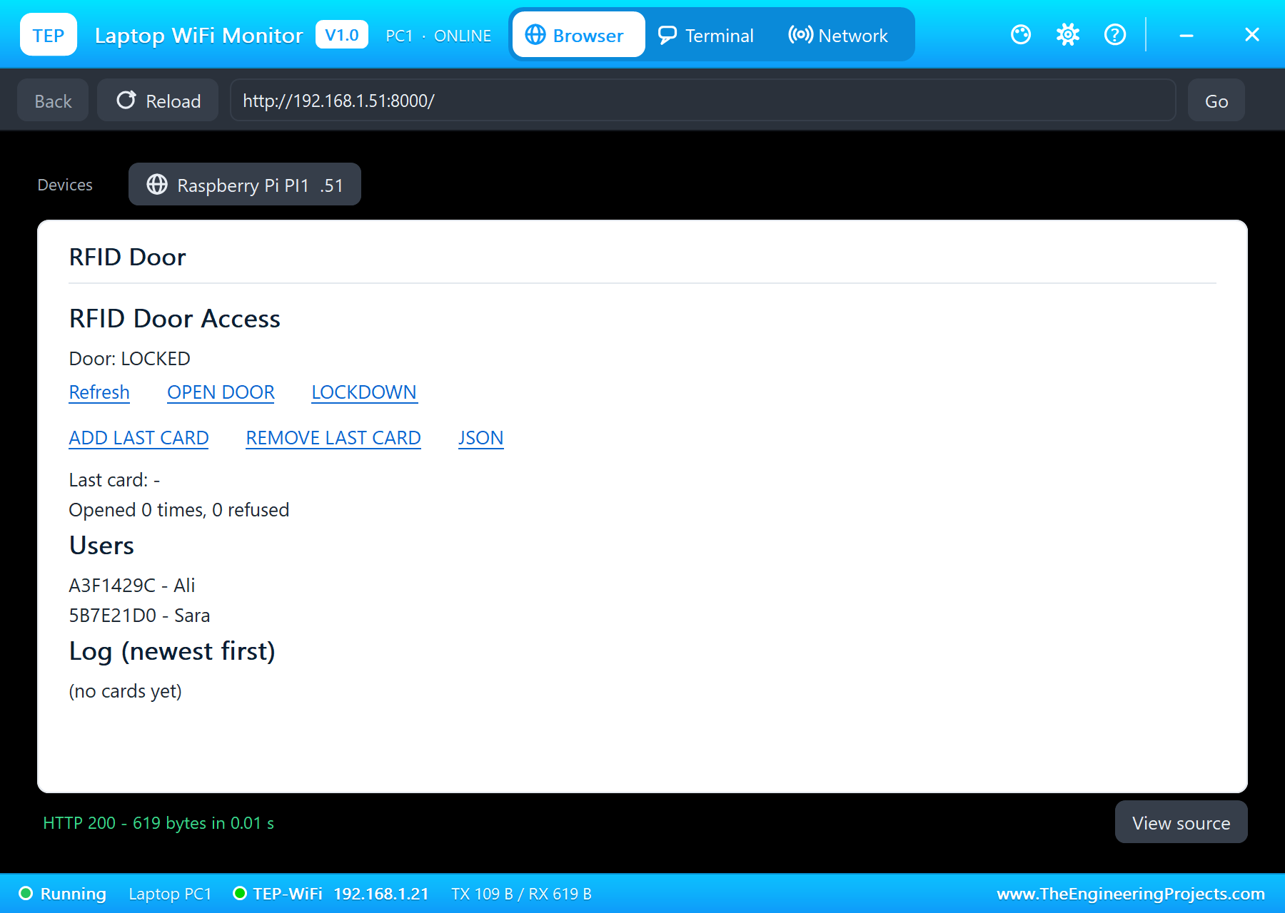
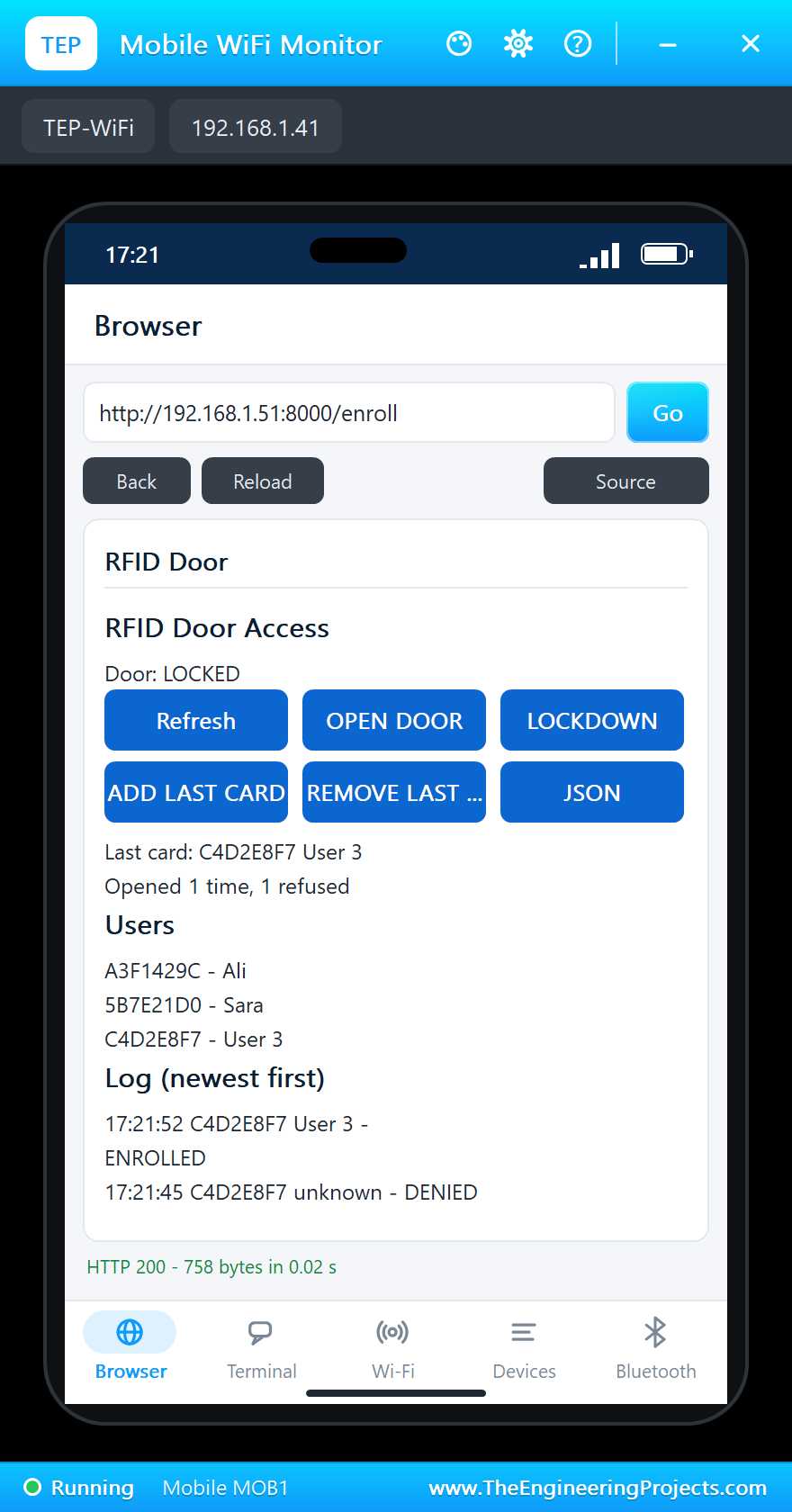
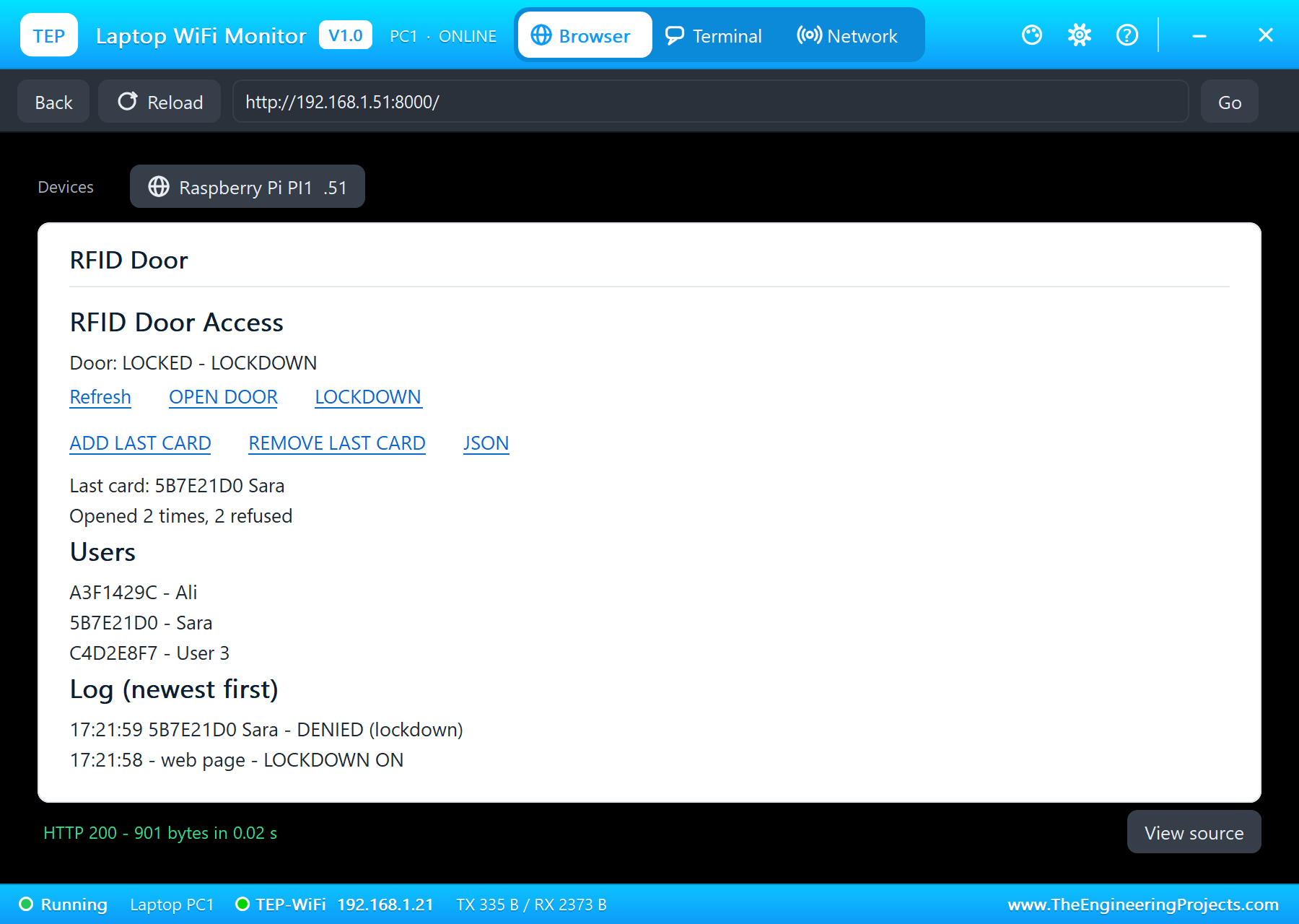
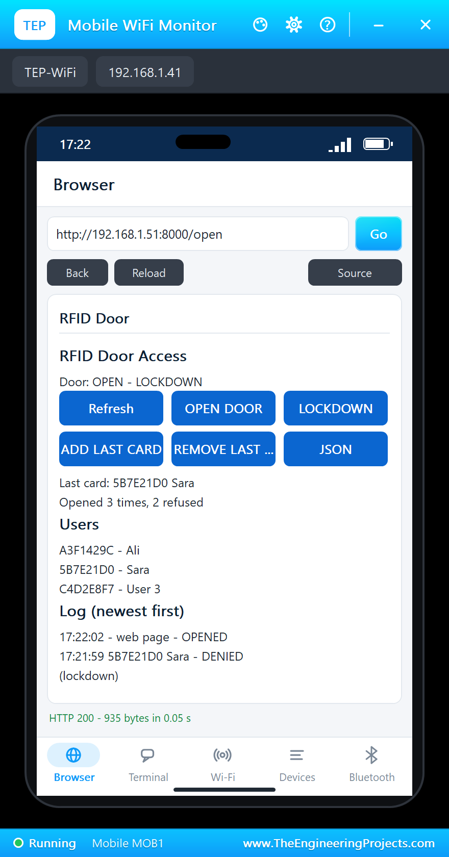
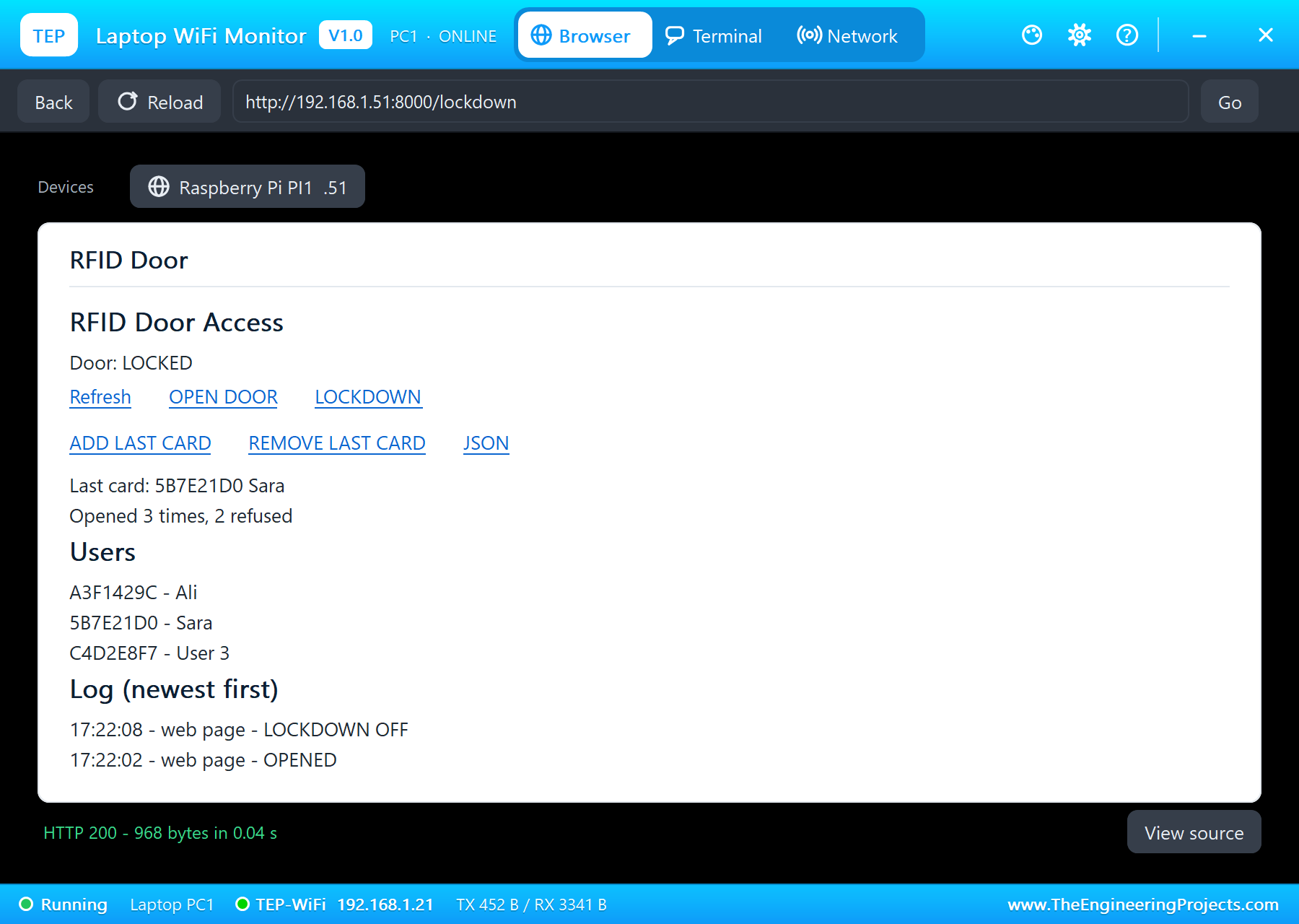
The page has two rows of links, which the phone shows as buttons: Refresh, OPEN DOOR and LOCKDOWN, then ADD LAST CARD, REMOVE LAST CARD and JSON. Below them are the door's state, the last card, the counts, the users and the newest ten log entries. ADD LAST CARD gives the last refused card a name such as "User 3"; in a real system you would type the person's name instead. The reader thread and the web server share the state, so every change happens under a lock, and the LCD has its own lock too, because both threads write to it.
How to Run the Proteus Simulation
- Download the project zip below and install the files, including the TEPPi folder.
- Open Pi-5-RFID-Door-Access.pdsprj from the Proteus Simulation folder. Keep
door_access.pyand the DLL files next to it. - Press Play. The Pi's terminal runs the program, and the LCD says "Door locked - Scan your card".
- Open the Laptop WiFi Monitor (PC1) or the Mobile WiFi Monitor (MOB1) and press Go.
- Click the RFID reader to open its pop-up, and press Tap on CARD 1 (Ali): the door opens for 3 seconds.
- Tap CARD 3 (the visitor): refused. Press ADD LAST CARD on the page and tap it again: welcome.
- Try LOCKDOWN, a card, and OPEN DOOR on the page. Press Refresh to see the log.
Proteus Simulation Results
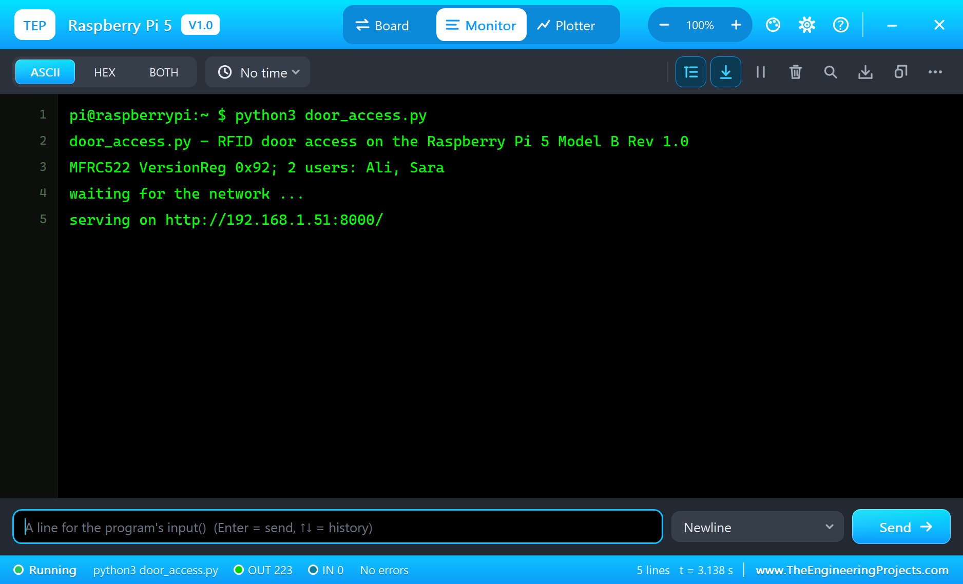
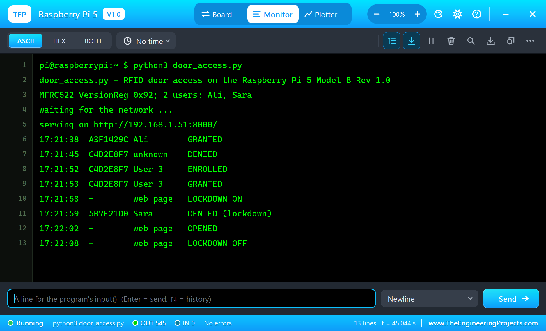
Here is one complete run of the simulation from our final test run. As soon as the program starts, it reads the reader's VersionReg, 0x92, which proves the SPI wiring, and lists the users:
The Dashboard and the Parts
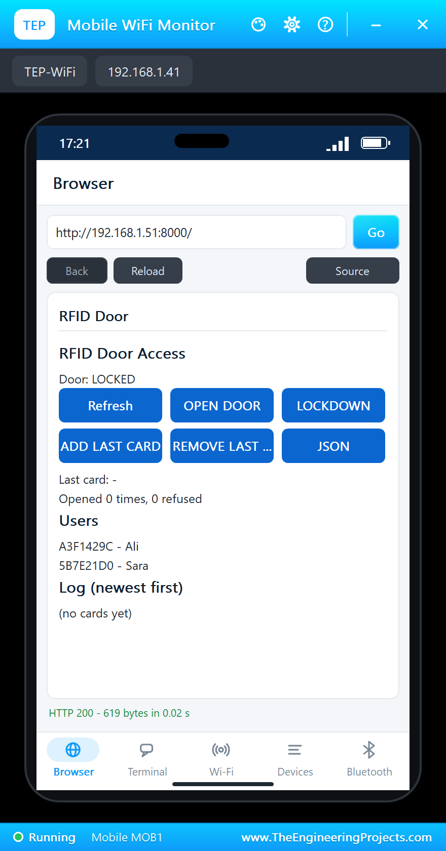
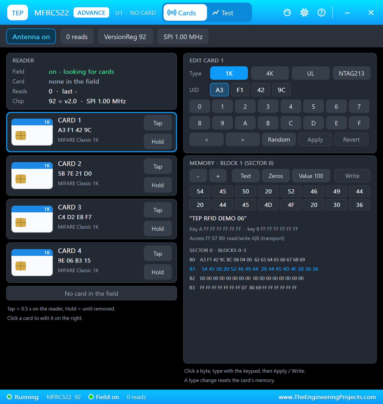
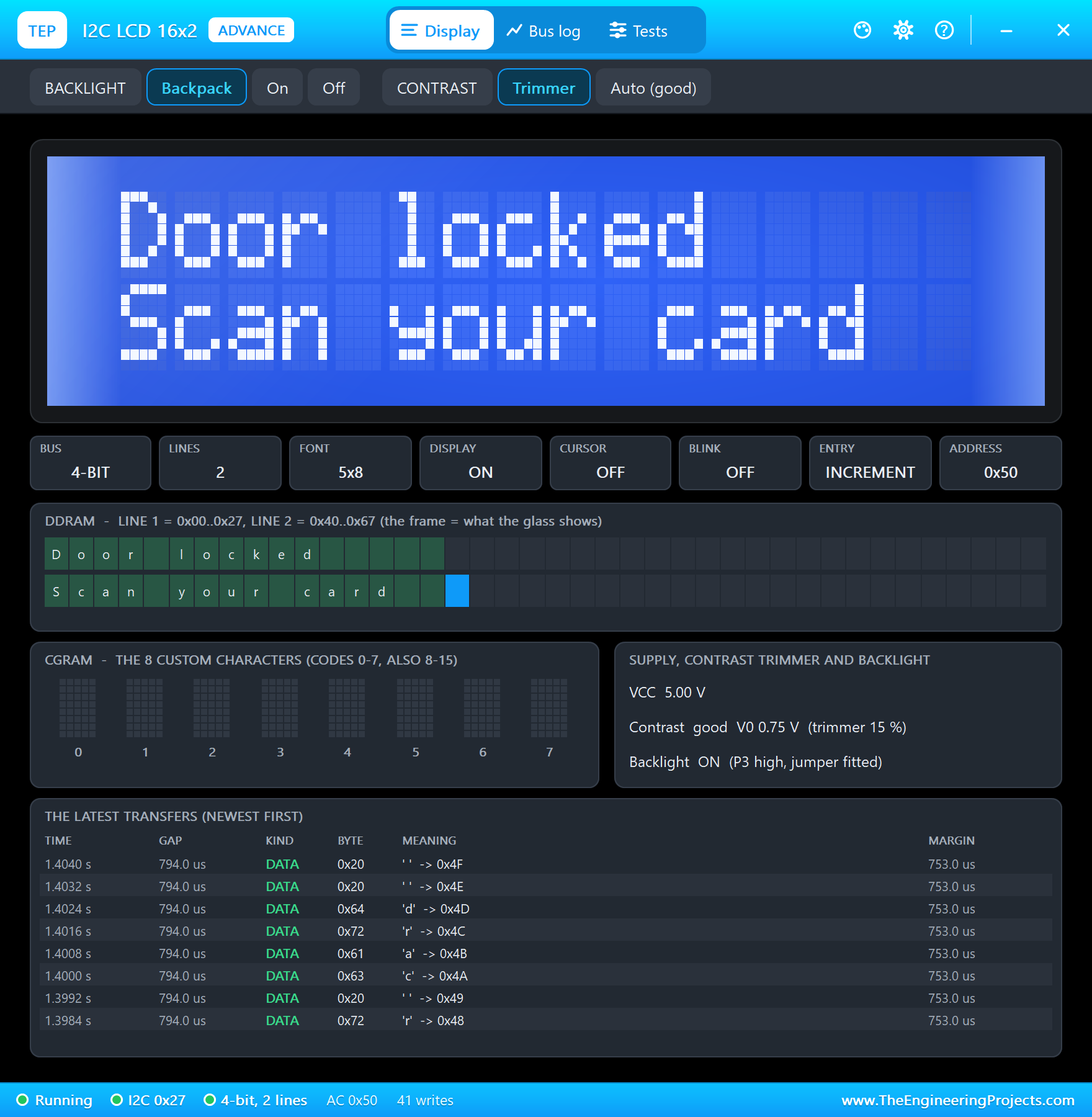
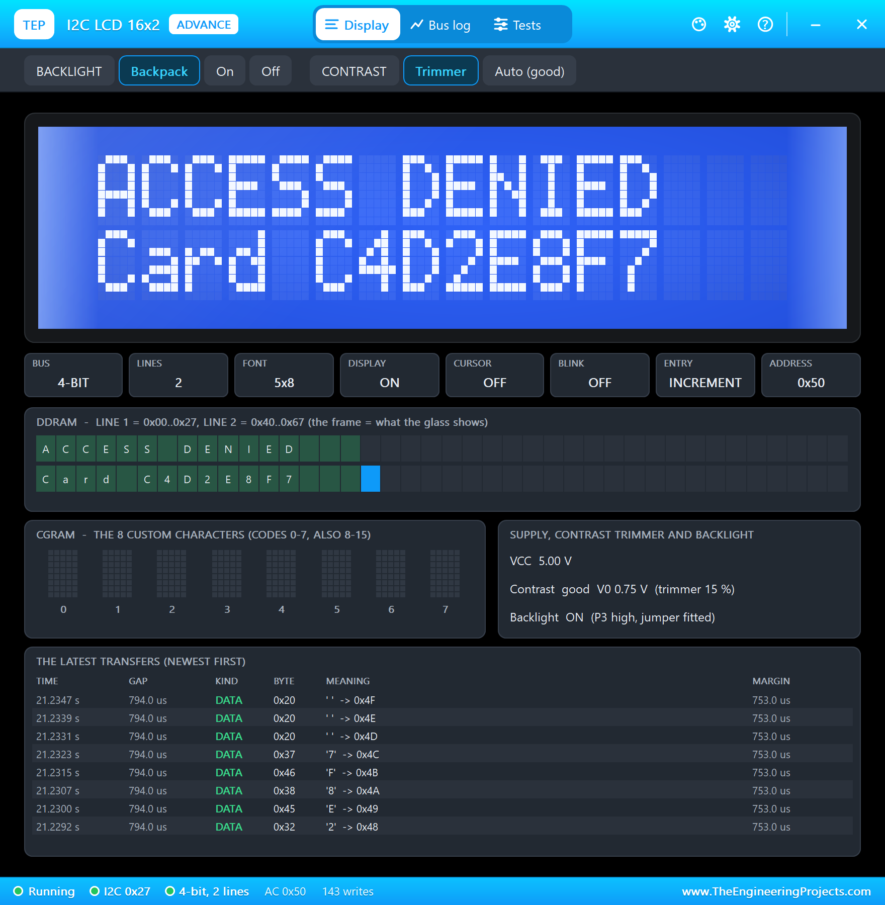
The LCD's pop-up shows every byte the Pi sends over I2C. Each character takes four PCF8574 writes, two for each nibble, and arrives about 0.8 ms after the previous one, so a whole 32-character screen updates in under 30 ms.
A Known Card: the Door Opens
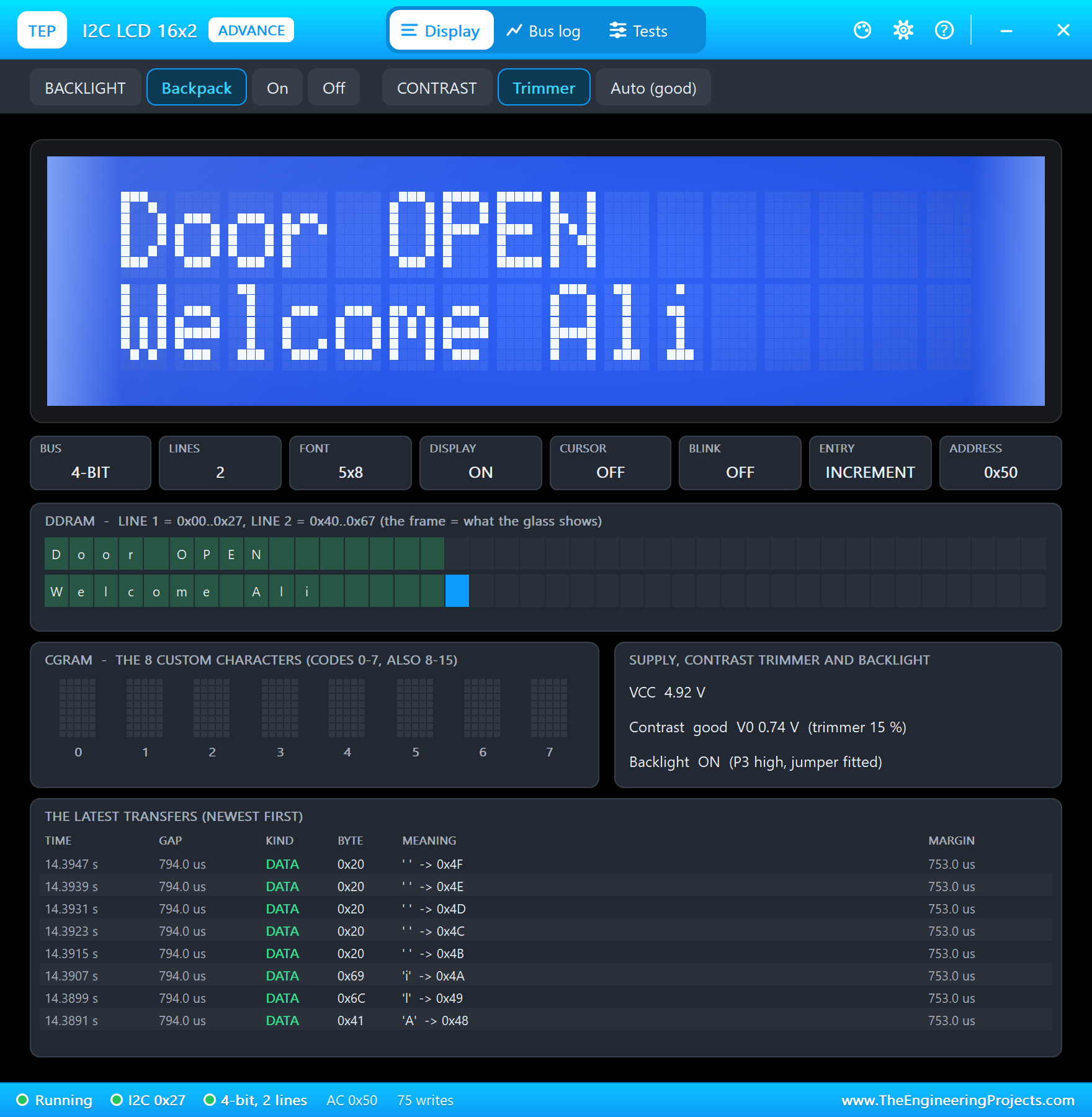
Ali's card is tapped. The terminal prints GRANTED, the LCD says "Door OPEN - Welcome Ali", the relay switches on, the solenoid pulls its plunger in and the green LED lights. Three seconds later, the door locks again.
An Unknown Card: Refused, then Enrolled
Next, the visitor's card. Its UID, C4D2E8F7, is not in the users, so the terminal prints DENIED, the LCD says "ACCESS DENIED - Card C4D2E8F7" and the red LED lights for a second. The reader's pop-up shows the card it just read.
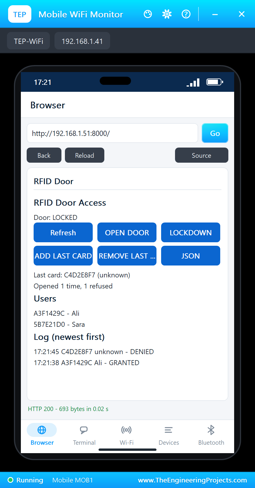
The visitor is allowed in from now on: ADD LAST CARD on the phone enrols C4D2E8F7 as "User 3". The users list grows and the log says ENROLLED. The visitor taps again, and this time the door opens.
Lockdown and a Remote Opening
LOCKDOWN on the laptop turns the door into a wall: Sara's card is refused with "DENIED (lockdown)", although Sara is a user. But OPEN DOOR from the phone still opens the door, because a lockdown stops the cards, not the person in charge. Finally, LOCKDOWN again on the laptop switches it off.
| Action | Result |
|---|---|
| Ali's card | GRANTED: the door open for 3 s, the green LED, "Welcome Ali" |
| The visitor's card | DENIED: the red LED, "ACCESS DENIED" |
| ADD LAST CARD (phone) | C4D2E8F7 ENROLLED as User 3 |
| The visitor's card again | GRANTED |
| LOCKDOWN (laptop), then Sara's card | DENIED (lockdown) |
| OPEN DOOR (phone) | OPENED, even in lockdown |
Download the Project Files
Click the button below to download Raspberry-Pi-5-RFID-Door-Access-Proteus-Simulation-v1.0.zip (about 14.8 MB, without the source code of the models):
Raspberry Pi 5 RFID Door Access - Proteus Simulation V1.0- Proteus Simulation: Pi-5-RFID-Door-Access.pdsprj, the program door_access.py and copies of the models.
- Python Code: door_access.py, the complete program.
- Proteus Library Files: the LIB files of the Raspberry Pi 5, the MFRC522, the I2C LCD, the relay, the solenoid, the LED, the resistor and the two WiFi Monitors.
- Proteus Model Files: the DLL models and the TEPPi folder with the Python 3.11 runtime the Pi board runs.
- README.txt: the installation steps, the properties, the test results and the links to every library post.
No Proteus yet? Read How to Download and Install Proteus 7 and 8. New to libraries? Follow How to Install a New Library in Proteus.
How to Install the Project Files
- Close Proteus and extract the whole zip file, for example to your Desktop.
- Copy the files from Proteus Library Files into the LIBRARY folder of Proteus.
- Copy everything in Proteus Model Files, the DLL files and the TEPPi folder, into the MODELS folder.
- Start Proteus and open the project from the Proteus Simulation folder.
Changing the Program
Edit door_access.py beside the project with any editor and press Play again. To change the cards, edit the users dictionary, or the reader's UID1 to UID4 properties. More about the Pi 5 board and the Python libraries it supports is in our Raspberry Pi 5 Library for Proteus, and our Raspberry Pi 5 PID Temperature Control is another Pi 5 project in this series.
Ideas to Extend the Project
- Save the users and the log to a file so they survive a restart.
- Add a keypad for a PIN as a second factor: a card and a code.
- Allow some cards only at certain hours, for example office hours.
- Add a door sensor (a reed switch) and an alarm if the door stays open too long.
- Read a name stored in the card's memory instead of keeping names on the Pi.
- Send an e-mail or a phone notification for every refused card.
From Simulation to Real Hardware
- Enable SPI and I2C: turn them on in
sudo raspi-configunder Interface Options. - Power the lock separately: the 12 V solenoid needs its own 12 V supply that can give about an ampere, and a flyback diode across its coil.
- Mind the I2C voltage: most PCF8574 backpacks pull SDA and SCL up to their own 5 V; use a level shifter, or remove those pull-ups so the Pi's own pull-ups keep the bus at 3.3 V.
- Keep the reader on 3.3 V: the MFRC522 is a 3.3 V chip; never power it from 5 V.
- Card security: a UID alone is easy to copy; for a real door, use the card's encrypted sectors or a more secure card type.
Troubleshooting
- The terminal cannot start Python: the TEPPi folder is not in MODELS, or an older one is there.
- "VersionReg 0x00": the SPI wires are not on SPI0, or the reader's SDA is not on CE0 (GPIO8).
- The LCD stays blank: its address is not 0x27, or SDA and SCL are swapped.
- A known card does not open the door: LOCKDOWN is on; the page and the LCD say so.
- A tapped card is not read: Tap holds it for only half a second; tap again or use Hold.
- The page does not change: press Refresh on the page; the browser's Reload would repeat the last link you pressed.
Limitations of the Simulation
- The network is simulated: the dashboard travels between the Pi and the two monitors inside Proteus.
- The program reads only the cards' 4-byte UIDs (cascade level 1); 7-byte UIDs would need a second anticollision step.
- The users and the log live in the program's memory and are lost when it stops.
- The browsers of the two monitors show text, links and one picture per page; forms and scripts are not simulated.
- Raspberry Pi, MIFARE and MFRC522 are names of their owners; this project is not made or endorsed by them or by Labcenter.
So, that was all about the Raspberry Pi 5 RFID Door Access - Proteus Simulation. I hope it gives you a solid start for your own access-control projects: a real RFID reader driven register by register, an LCD over I2C, a relay lock and a web page to manage it all, tested in a simulation before you touch a real door. More IoT projects with the Raspberry Pi 5 and the ESP32 are coming in this series. If you have any questions, ask in the comments and I will help you out. Till the next tutorial, take care and have fun!

Comments
0