


NE555 Timer Library for Proteus Simulation


Hello friends, I hope you all are doing great. Today, I am going to share the new NE555 Timer Library for Proteus Simulation, the fourth of the lab ICs in our University Lab series. If you have searched for a Proteus simulation of the 555 timer, this library is for you. The 555 is the most famous chip in electronics: since 1972 it has blinked LEDs, made tones, debounced switches, generated PWM and timed everything from toasters to traffic lights. Every electronics course has a 555 lab, and every student builds the astable blinker at least once.
NE555 Timer Library for Proteus Simulation
Latest version: V1.0 (November 2026, this tutorial)
Helping Tools
- Serial Monitor Advance: a serial terminal window for the UART of your board
- Serial Monitor Expert: the serial monitor with extra debugging tools
- LCD Library for Proteus V3.0: 16x2, 20x4 and I2C LCDs to show your readings
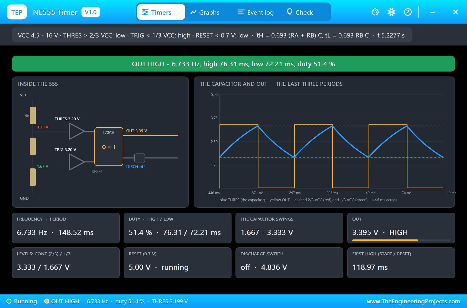
Our library brings the real chip into your Proteus simulation: the NE555 in its PDIP-8 package, drawn at its true size of 9.81 x 6.35 mm. Inside, the simulation model follows TI's datasheet: the resistor divider that sets the 1/3 and 2/3 levels, the two comparators, the latch with RESET in charge, the output stage and the discharge switch. The pop-up shows the inside of the chip live, with a scope of the capacitor and the output. The demo is the classic astable with an LED, timed and reset by an Arduino, and the simulation results agree with the formulas to a fraction of a percent, except where the real chip itself does not.
NOTICE: Our team has put a lot of effort into these small parts: the bodies, the animation and the pop-ups are all our own design, and you get them free. Your feedback is the fuel that keeps us going, so please tell us what you think in the comments below or in the NE555 board of our forum. And if our free libraries help you, you can buy us a coffee. So, let's get started with the NE555 Timer Library for Proteus Simulation:
What is the NE555 Timer?
The NE555 is a timer chip that turns a resistor and a capacitor into an accurate time interval. It can run as a monostable, giving one pulse of a fixed length each time it is triggered, or as an astable, a free-running oscillator that switches its output high and low forever. It runs from 4.5 V to 16 V, its output can source or sink 200 mA, and the timing depends only on the resistors and the capacitor, not on the supply voltage. That last point is the secret of its success.
| NE555 (VCC = 5 V, 25 °C) | |
|---|---|
| Supply | 4.5 V to 16 V; 3 mA with the output low, 2 mA high (no load) |
| THRES level | 3.3 V typical (2/3 VCC); THRES current 30 nA |
| TRIG level | 1.67 V typical (1/3 VCC); TRIG current 0.5 uA at 0 V |
| RESET | 0.7 V typical (0.3 V to 1 V); -0.4 mA at 0 V |
| CONT | 3.3 V open circuit (2/3 VCC) |
| Output low | 0.1 V at 5 mA, 0.15 V at 8 mA |
| Output high | 3.3 V at -100 mA |
| Discharge switch | 0.15 V at 8 mA on; 20 nA off |
| Output current | 200 mA source or sink; edges of about 100 ns |
The Pins
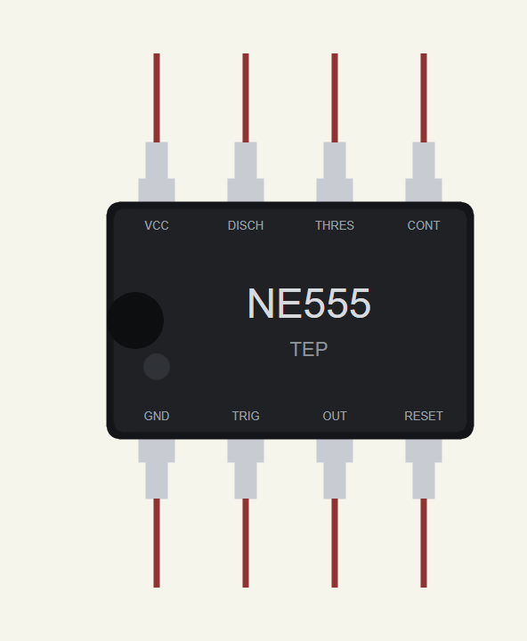
Pin 1 is GND, 2 is TRIG (trigger), 3 is OUT, 4 is RESET, 5 is CONT (control voltage), 6 is THRES (threshold), 7 is DISCH (discharge) and 8 is VCC. Our drawing lies on its side with the notch on the left: pins 1 to 4 along the bottom, 8 to 5 along the top, each name printed small next to its leg, so the simulation circuit reads like the real board.
How the 555 Works Inside
The divider. Three equal resistors in series from VCC to GND (5 kΩ each in the classic design, which is where many people say the name comes from) make two reference levels: CONT at 2/3 VCC and an inner tap at 1/3 VCC. On 5 V these are 3.333 V and 1.667 V.
The comparators. The threshold comparator watches THRES against CONT, and the trigger comparator watches TRIG against the 1/3 tap. When THRES rises above 2/3 VCC, the output goes low. When TRIG falls below 1/3 VCC, the output goes high.
The latch. Between those two events the chip remembers its last state: it is a set-reset flip-flop. RESET overrides everything: below 0.7 V it forces the output low, whatever the comparators say. Next comes TRIG, and THRES last.
The output and the discharge switch. When the output is low, a transistor on DISCH is switched on and pulls that pin to ground; when the output is high, it is off. That switch is what empties the timing capacitor.
The Astable Formulas
In the astable circuit, RA goes from VCC to DISCH, RB from DISCH to THRES and TRIG, and C from THRES and TRIG to ground. While the output is high, C charges through RA + RB from 1/3 to 2/3 VCC; while it is low, DISCH pulls the bottom of RB to ground and C empties through RB from 2/3 back to 1/3 VCC. Both moves cover the same ratio of the way, which gives ln 2 = 0.693:
- tH = 0.693 (RA + RB) C, the high time;
- tL = 0.693 RB C, the low time;
- f = 1.44 / ((RA + 2 RB) C), and the duty is (RA + RB) / (RA + 2 RB), always above 50 %.
With RA = 1 kΩ, RB = 10 kΩ and C = 10 uF the formulas give tH = 76.2 ms, tL = 69.3 ms, 6.86 Hz and a duty of 52.4 %. Keep those numbers in mind: the simulation will show one of them is a little optimistic.
Features of the NE555 Timer Library for Proteus Simulation
- The real chip at true scale: the PDIP-8, 9.81 x 6.35 mm, with its real pinout.
- The inside from the datasheet: the divider, both comparators, the latch with RESET over TRIG over THRES.
- A real output and discharge switch: high at VCC - 1.6 V, low at 0.05 V, the discharge switch at 18 Ω (0.15 V at 8 mA).
- Accurate timing: the simulation step shrinks as the capacitor nears a level, so every switching point is caught within a microsecond.
- RESET with its pull-up current and the supply current of the chip.
- A threshold error (TOL): move the 2/3 point and see the timing change, like a real part out of the middle of its range.
- A pop-up: the inside live, a scope of the last three periods, the frequency, the duty, the first cycle, graphs, an event log and a check page.
- A complete package: about 2.5 MB with the library, our resistor, capacitor and LED parts, our Arduino UNO V4.0 and the demo, without the source code of the model.
The NE555 in Proteus
The device is NE555TEP in TEPNE555.LIB, under Lab ICs > Timers, with the prefix U and the analog model TEPNE555.DLL. Search NE555 in Pick Devices. Its one property, TOL, moves the threshold level by a percentage of VCC; leave it at 0 for the typical chip, or try +5 or -5 to see how a real part with its levels away from the middle changes the timing of your simulation.
Download NE555 Timer Library for Proteus Simulation
Click the button below to download NE555-Timer-Library-for-Proteus-v1.0.zip (about 2.5 MB, without the source code of the models):
NE555 Library for Proteus V1.0- README.txt: installation, the demo, the wiring, troubleshooting and the limits of the simulation.
- Proteus Library Files:
TEPNE555.LIB, ourTEPRESISTOR.LIB,TEPELECTRO.LIB,TEPCERAMIC.LIB,TEPLED5MM.LIBandArduinoV4TEP.LIB. - Proteus Model Files:
TEPNE555.DLL, the four parts' DLLs andTEPARDUINO.DLL. - Arduino Code: the demo sketch.
- Proteus Simulation: the demo project, its HEX file and copies of the DLLs.
No Proteus yet? Read How to Download and Install Proteus 7 and 8. New to libraries? Follow How to Install a New Library in Proteus.
How to Install NE555 Timer Library for Proteus Simulation
- Close Proteus and extract the whole zip file, for example to your Desktop.
- Copy the files from Proteus Library Files into the LIBRARY folder of Proteus.
- Copy the files from Proteus Model Files into the MODELS folder.
- Delete
TEPNE555.IDXfrom the LIBRARY folder if it is there. - Start Proteus, press P and search for NE555.
Proteus Simulation of the NE555 Astable
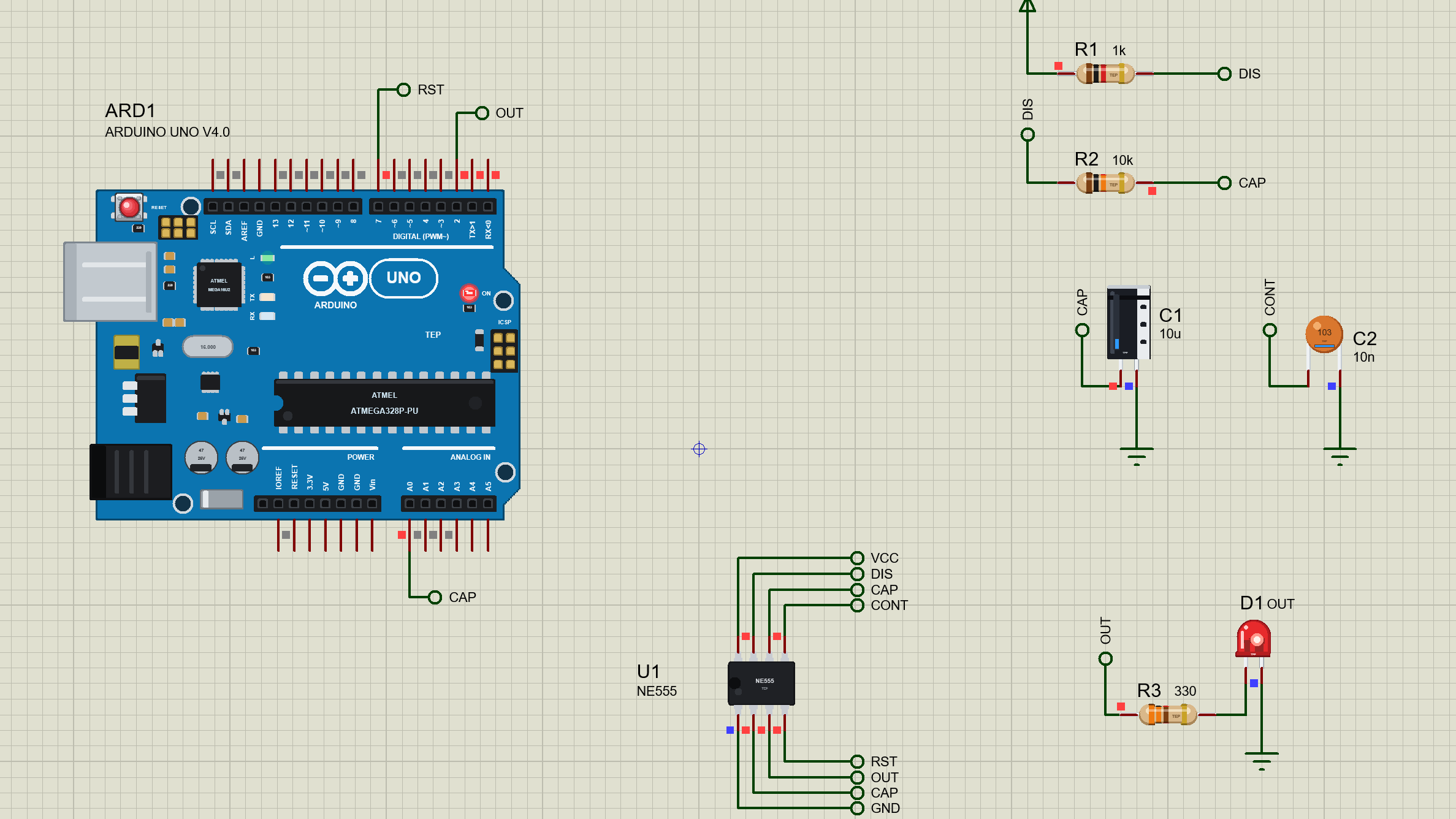
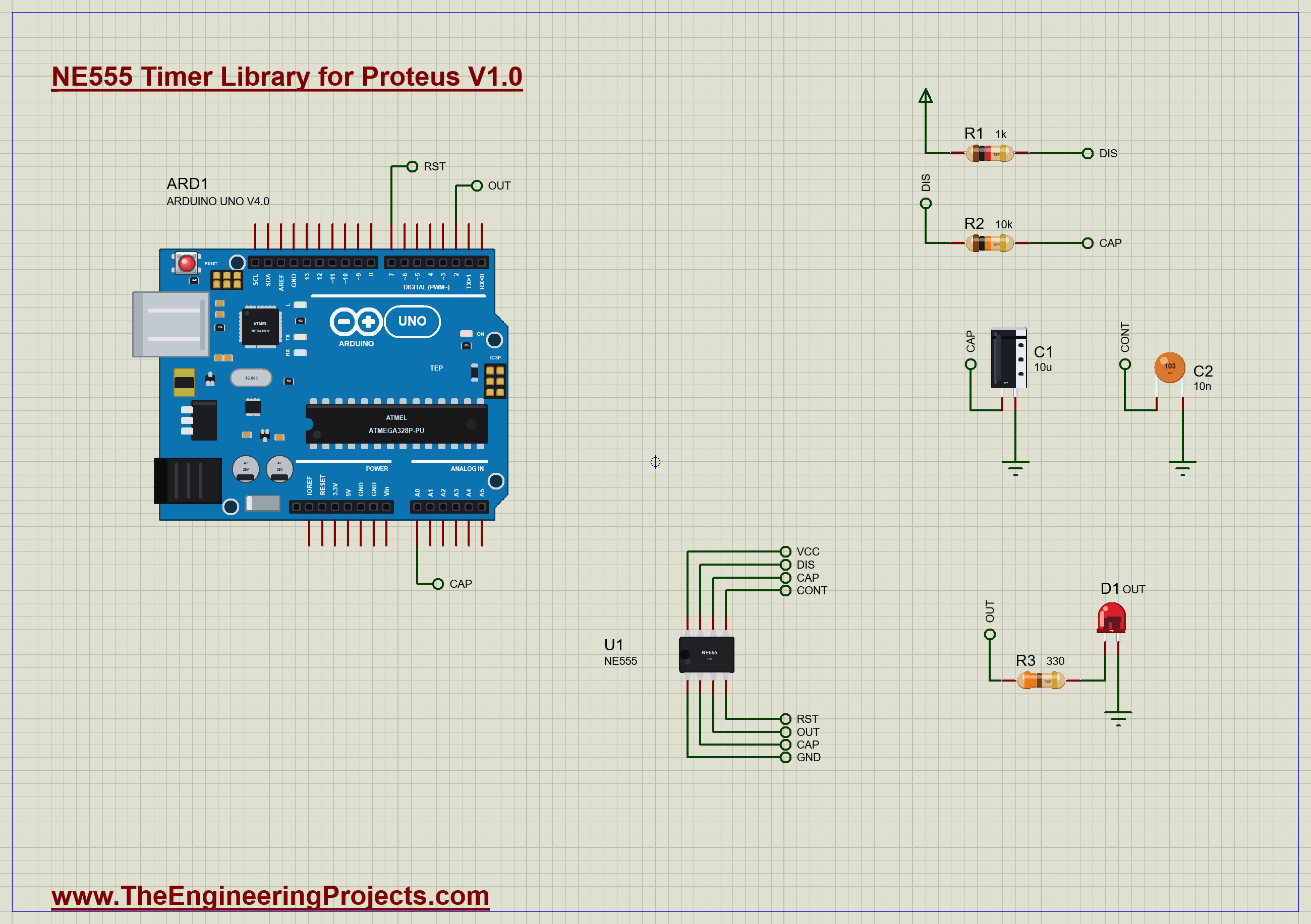
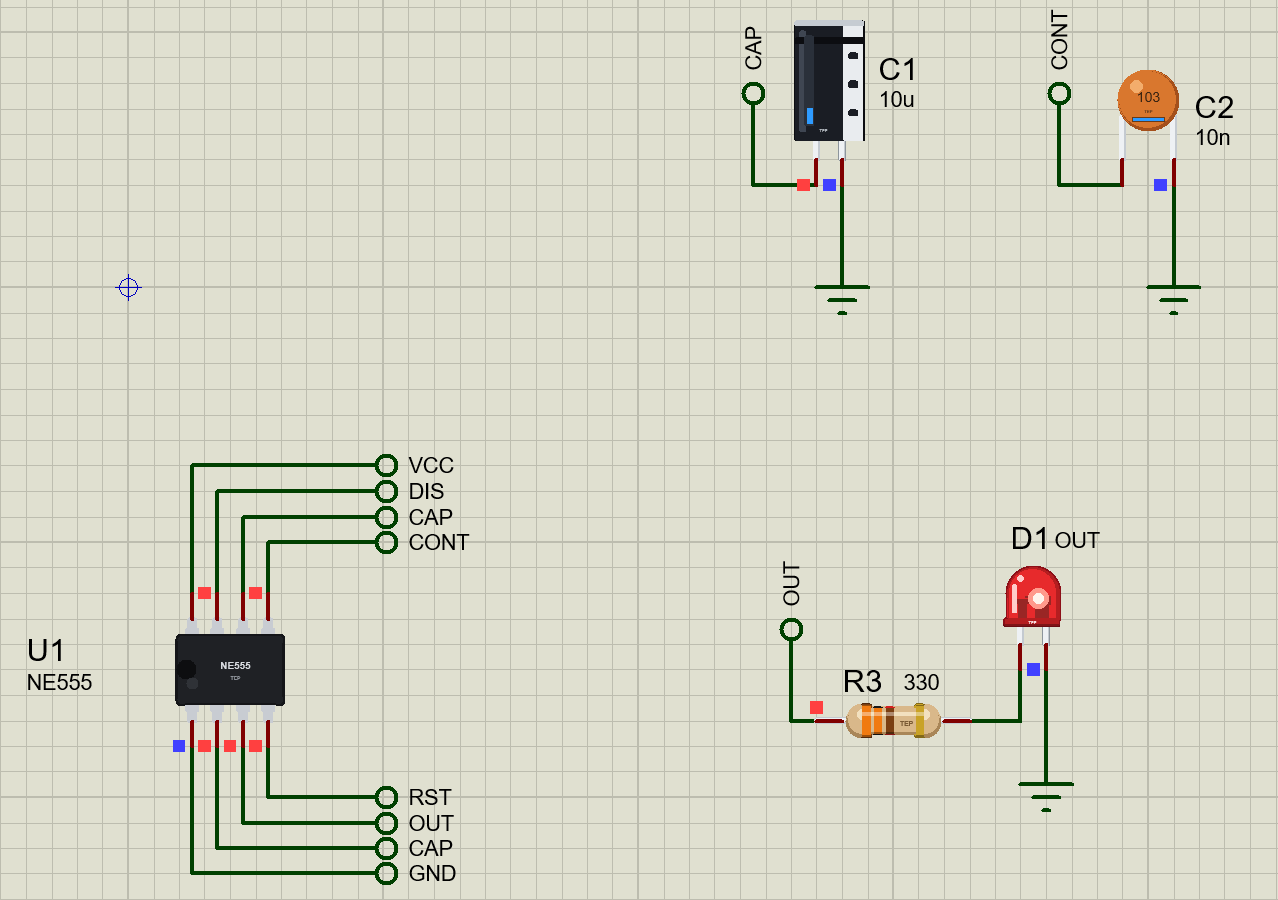
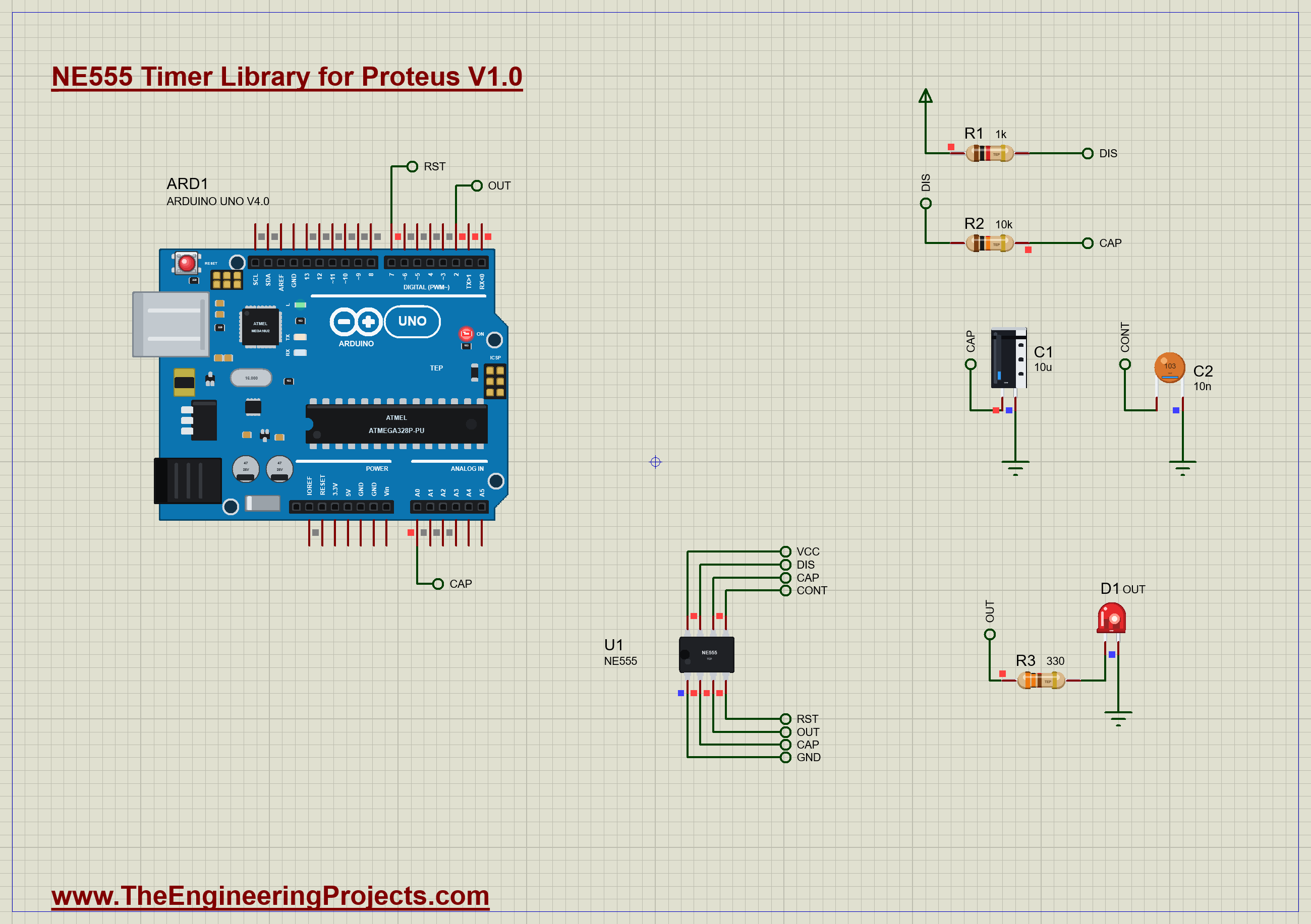
The demo has our Arduino UNO Library for Proteus V4.0 with its built-in monitor, the same window as our TEP Serial Monitor Advance for Proteus, and the NE555 on 5 V wired as the classic astable. R1 is RA (1 kΩ, VCC to DISCH), R2 is RB (10 kΩ, DISCH to THRES and TRIG), C1 is a 10 uF electrolytic from THRES and TRIG to ground, and C2, a 10 nF ceramic, sits on CONT as the datasheet recommends. A red 5 mm LED with R3 (330 Ω) hangs on OUT, so the simulation blinks just like the breadboard does. The resistors, capacitors and LED are our own Proteus parts, each with its own pop-up. OUT also goes to the UNO's D2, the capacitor to A0, and D7 drives RESET. Open NE555-Astable-ArduinoUnoV4.pdsprj.
The Sketch
The UNO is the lab's oscilloscope and frequency counter. It times the high and low periods on D2 with micros(), which counts in 4 us steps from a hardware timer, by waiting for each edge with a small helper:
bool waitFor(int level) {                                                     // until D2 reads `level`; false after 1 s
  unsigned long t0 = micros();
  while (digitalRead(OUT_PIN) != level) if (micros() - t0 > 1000000UL) return false;
  return true;
}
Three edges in a row, rising, falling and rising again, give one high time and one low time:
    unsigned long t1 = micros();
    waitFor(LOW);  unsigned long t2 = micros();
    waitFor(HIGH); unsigned long t3 = micros();
    unsigned long th = t2 - t1, tl = t3 - t2;
We first used pulseIn(), but it counts loop cycles rather than reading a timer, and it read about 0.6 % short; micros() matches the simulation's own clock. After three periods the sketch reads A0 as fast as it can for 450 ms and keeps the lowest and highest values: the capacitor's swing. Then it pulls RESET low for 1.5 s, releases it and times the first high period that follows. One more detail sits at the top of setup():
  digitalWrite(RST_PIN, HIGH);                                                // HIGH first, then OUTPUT: RESET never sees a low glitch
  pinMode(RST_PIN, OUTPUT);
A pin becomes an output with its last written level. Our first version set the pin to OUTPUT first, and for a few microseconds D7 drove RESET low; the simulation caught it as a real reset at 65 ms. The real chip would see it too, so the order matters on the bench as well.
NE555 Simulation Results
Open the project and press Run. The demo runs about 5 simulated seconds, which Proteus ran in about two minutes on our PC with the pop-up open. Click the chip to open its pop-up; every number below comes from one simulation run, the demo exactly as it ships.
The Astable in Numbers
The capacitor swings between exactly 1.667 and 3.333 V: CONT sits at 0.667 of VCC and the trigger level at 0.333. The pop-up's scope shows the familiar picture, the blue capacitor voltage climbing to the red 2/3 line while OUT is high, then falling to the green 1/3 line while OUT is low. The simulation measures a high time of 76.306 ms and a low time of 72.214 ms: 6.7331 Hz with a duty of 51.38 %.
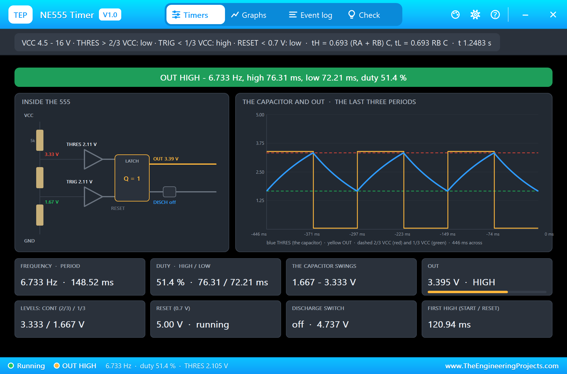
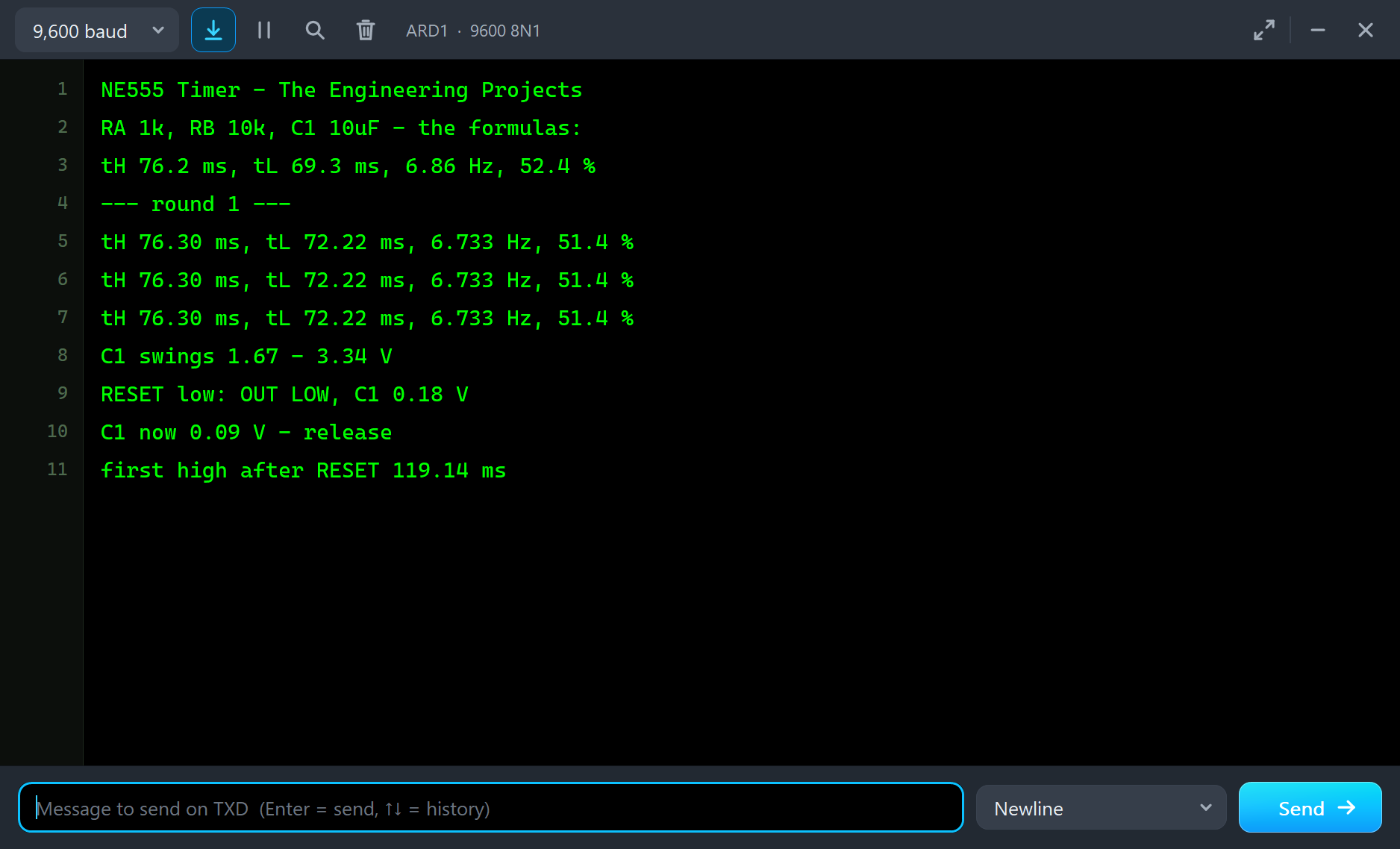
The UNO agrees to the last digit it prints: tH 76.30 ms, tL 72.22 ms, 6.733 Hz, 51.4 %, and A0 reads the swing as 1.67 to 3.34 V, within one step of its converter. The high time matches the formula: 0.693 x 11 kΩ x 10 uF = 76.2 ms. The low time does not: 72.2 ms instead of 69.3 ms.
Why the Low Lasts 72 ms, Not 69 ms
This is not a simulation error; it is what a real 555 does with a small RA. The formula assumes the discharge switch pulls DISCH all the way to 0 V. But while the switch is on, R1 still pours current into it from VCC: 5 V across 1 kΩ is about 5 mA. The datasheet gives the switch 0.15 V at 8 mA, and our model's 18 Ω gives 0.091 V at the end of the low period. So the capacitor does not empty toward 0 V but toward 0.091 V, and it takes longer to fall from 3.333 to 1.667 V:
- tL = RB C ln((2/3 VCC - Vd) / (1/3 VCC - Vd)) = 100 ms x ln(3.242 / 1.576) = 72.1 ms.
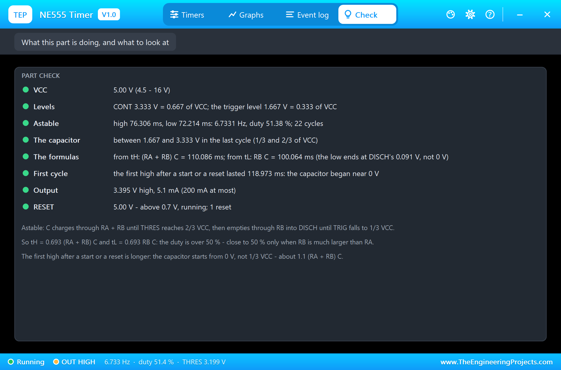
The Check page does this sum backward from the simulated times: (RA + RB) C = 110.086 ms from tH, and RB C = 100.064 ms from tL with the floor taken in, against the true 110 ms and 100 ms. On the bench, a larger RA (10 kΩ or more) makes the effect almost vanish; with 1 kΩ, plan on a frequency about 2 % lower than the formula, 6.733 Hz here instead of 6.86 Hz.
RESET Takes Over
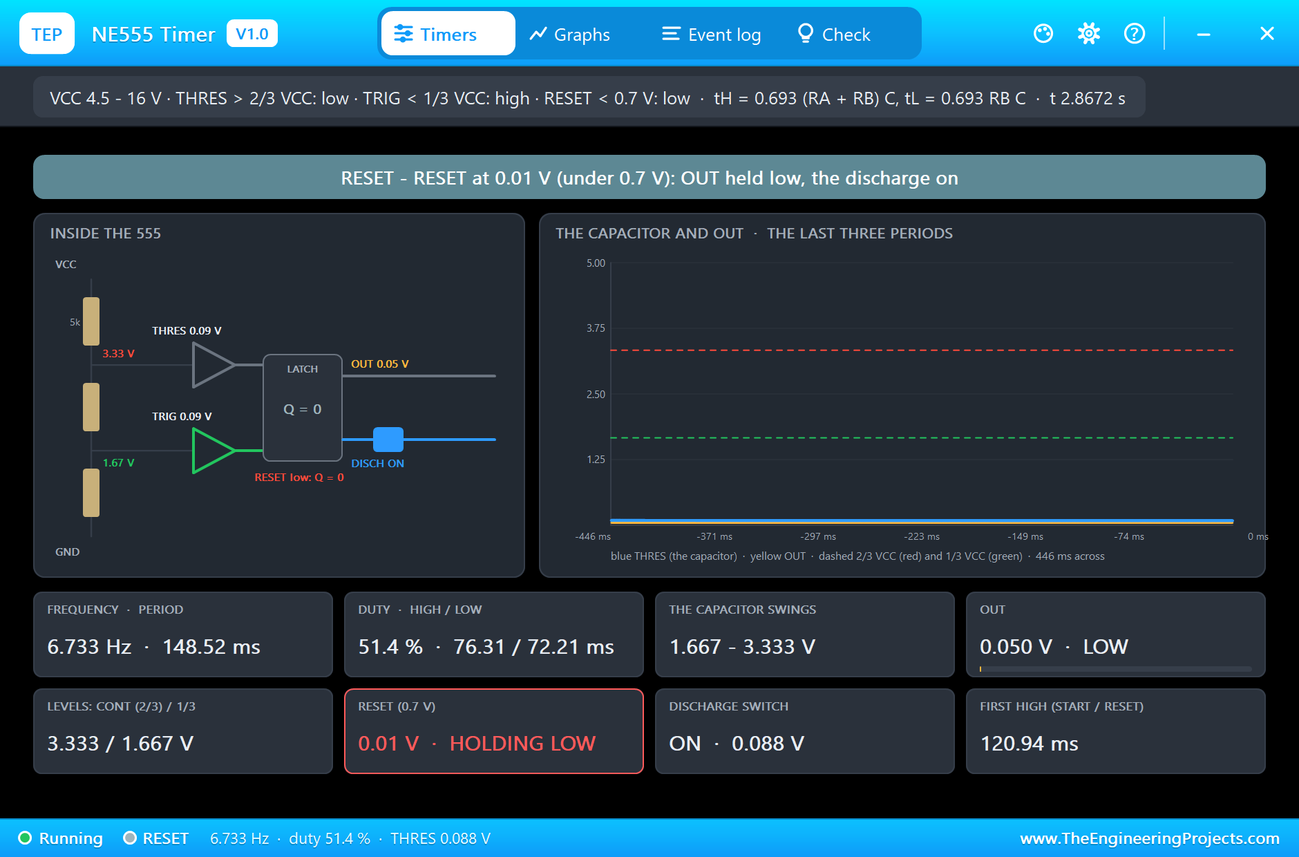
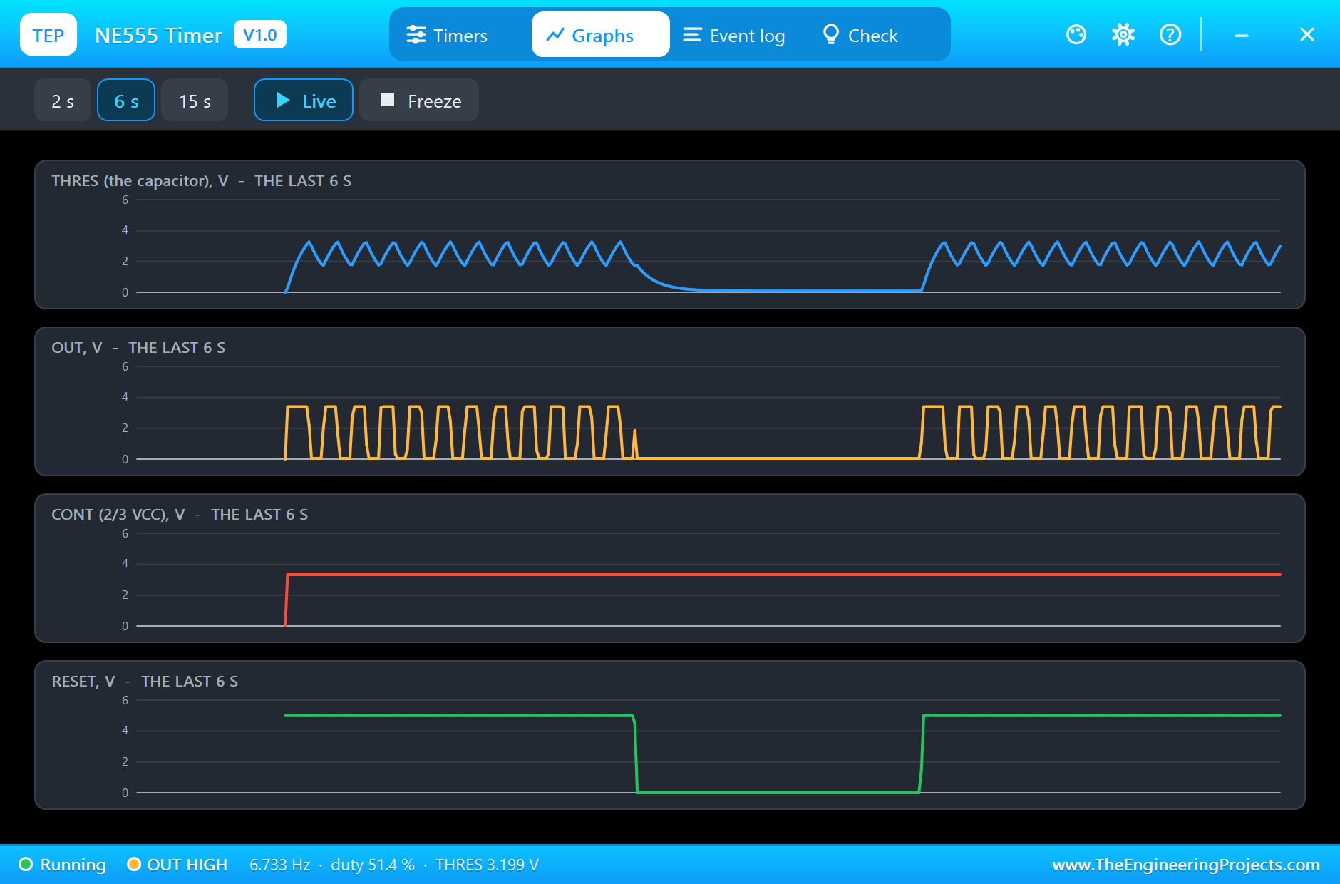
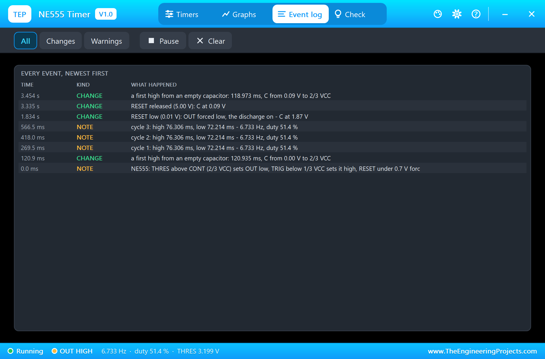
At 1.834 s the sketch pulls RESET low. The capacitor is at 1.87 V at that moment, in the middle of a cycle, but it does not matter: RESET overrides both comparators, OUT drops low and the discharge switch turns on. The pop-up's banner turns grey-blue, the latch shows Q = 0 with "RESET low" under it, and the scope shows the capacitor draining through R2. After 300 ms the UNO reads OUT LOW and C1 at 0.18 V; by the release, C1 has settled at 0.09 V, the same floor as before.
The First Cycle Is Longer
When RESET is released at 3.335 s, TRIG is far below 1/3 VCC, so the output goes high at once and the capacitor starts charging, but from 0.09 V instead of 1.667 V. The first high period therefore lasts longer: the simulation measures 118.973 ms and the sketch 119.14 ms, including its own loop time. The same happens at power-up, where the capacitor starts from exactly 0 V: 120.935 ms, the ln 3 (RA + RB) C = 120.85 ms that datasheets round to 1.1 RC. Watch the first blink of any 555 circuit and you will see it is a little longer than the rest.
The Graphs, the Log and the Check Page
The Graphs page plots THRES, OUT, CONT and RESET over the last 2, 6 or 15 simulated seconds. The whole story of the demo is in that page: the first longer ramp from 0 V, the steady sawtooth, the drain to the floor while RESET is low, and the restart. The Event log records each step with its time: the first high, the first cycles, RESET low with the capacitor voltage at that moment, and the release.
The Check page sums up the chip: the supply, the two levels as fractions of VCC, the astable's times, frequency and duty, the capacitor's swing, the formulas worked backward, the first cycle, the output's level and current (3.395 V and 5.1 mA into the LED), and RESET.
Try It Yourself
- Change R1 to 10 kΩ and see the low time move close to the formula: the discharge floor almost disappears.
- Make R2 much larger than R1 (1 kΩ and 100 kΩ) and watch the duty fall toward 50 %.
- Set TOL to +5 and see the high and low times both grow, as the capacitor has further to go.
- Remove C2 and drive CONT from the UNO through a resistor: the frequency follows the voltage.
- Turn the astable into a monostable: TRIG from a push button, THRES and DISCH together, and time the pulse at 1.1 RC.
- Run the 555 from 9 V (disconnect D2 and A0 first) and see the frequency stay the same while the levels scale.
Ideas to Extend the Demo
- Add a diode across R2 for a duty under 50 %, and measure it with the UNO.
- Build a tone generator: a small capacitor, a few kilohertz, and our passive buzzer part on OUT.
- Make a PWM dimmer: two diodes and a potentiometer for a fixed frequency and a variable duty.
- Use the LM358 from our earlier library as a buffer for the capacitor voltage, so the UNO's input never loads it.
Your Own Sketches
The demo sketch is in the zip file, and you can change it in the Arduino IDE. New to Arduino? Start with our Arduino Tutorial for Beginners. Export the compiled binary, and set the UNO's PROGRAM property to the new file. Our guide on How to get the HEX file from Arduino shows you where the file ends up.
Things to Know Before Using a Real Chip
- The discharge switch is not perfect: with a small RA the low time is longer than 0.693 RB C; choose RA of a few kilohms or more.
- Use a good timing capacitor: electrolytics often have 20 % tolerance and leak; a film capacitor keeps the timing accurate.
- Decouple it: 10 nF on CONT and 100 nF across VCC; the output's switching current is large.
- The output is not rail to rail: about 3.3 V high on 5 V; the CMOS versions (TLC555, LMC555) swing to the supply.
- Keep RA + RB under about 3.4 MΩ on 5 V: the THRES current sets that limit.
Troubleshooting
- NO SUPPLY: VCC is missing or under 2 V; a warning appears below 4.5 V.
- OUT stays low: RESET is under 0.7 V; tie it to VCC or drive it HIGH.
- The frequency is a little lower than the formula: the discharge pin does not reach 0 V; the Check page gives RB C back.
- The first period after Run is longer: the capacitor starts from 0 V, not from 1/3 VCC.
- An over-current warning: OUT drives more than 200 mA.
- The part is not simulated:
TEPNE555.DLLis missing from MODELS and from the project folder.
Limitations of the Simulation
- The comparators' input currents are reduced to a tiny leak; the 30 nA THRES current matters only with resistors of megohms.
- The output switches in one simulation step; the 100 ns edges and the supply spike they cause are not modelled.
- The high output level is a fixed source with 1 Ω; the real level falls a little more with heavy loads.
- Temperature drift and the supply sensitivity of the timing are not modelled.
- Arduino is a name of Arduino and NE555 is an industry part number; this library is not made or endorsed by Arduino, Labcenter or Texas Instruments.
- Tested in Proteus 8.5 in November 2026 (the demo as shipped). Proteus 7 is not supported.
So, that was all about the NE555 Timer Library for Proteus Simulation. I hope it helps you run your 555 labs on your own PC first: real thresholds, a real discharge switch, and a simulation that shows why the bench never quite matches the textbook. If you have any questions, ask in the comments and I will help you out. Till the next tutorial, take care and have fun!

Comments
0