


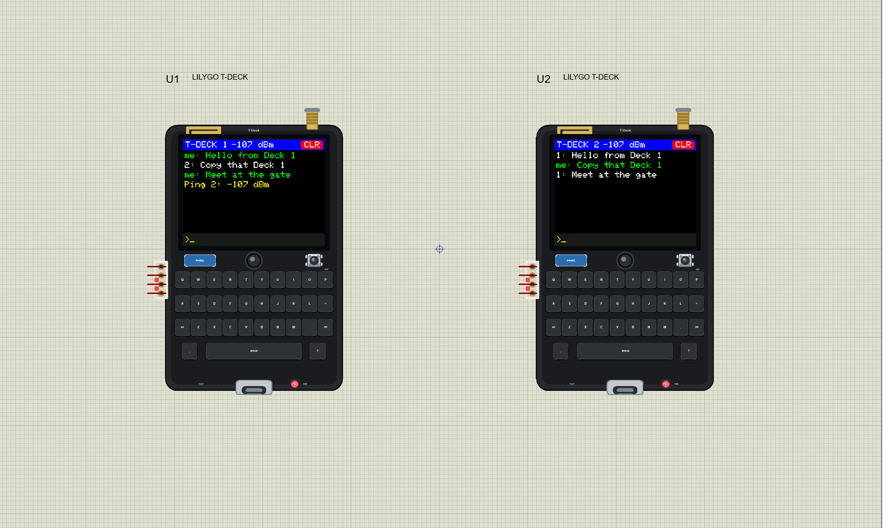
LilyGO T-Deck Library for Proteus: ESP32 TFT LCD, Keyboard, LoRa


Hello friends, I hope you all are doing great. Today, I am going to share the LilyGO T-Deck Library for Proteus. The T-Deck looks like a little BlackBerry phone: an ESP32-S3, a 2.8 inch colour TFT LCD with a touch screen, a real QWERTY keyboard, a trackball and a LoRa radio, all in one handheld. With this library it runs your ESP32 Arduino sketch in Proteus 8.5, and the display, the keyboard, the touch and the radio all work on the part.
LilyGO T-Deck Library for Proteus
Latest version: V1.0 (November 2026, this tutorial)
Helping Tools
- Laptop WiFi Monitor: a laptop on the Wi-Fi of your design: a browser, a TCP / UDP terminal and ping
- Mobile WiFi Monitor: a smartphone that opens the pages of your board and sends it commands
- Serial Monitor Advance: a serial terminal window for the UART of your board
For the demo we built a LoRa messenger. Two T-Decks sit on the sheet with no wires between them, one kilometre apart. You type on one keyboard, press OK, and the message appears on the other screen. The other T-Deck answers with an acknowledgement, and your line turns green. There is no Wi-Fi, no SIM card and no network anywhere: just two radios and a few pages of Arduino code.
NOTICE: Proteus has no ESP32 model, so our team has put a lot of effort into building this board ourselves: the T-Deck's display, keyboard, touch screen and LoRa radio are all our own model, and your sketch compiles with our free TEP Boards for Proteus add-on. Your feedback is the fuel that keeps us going, so please tell us what you think in the comments below or in the LilyGO T-Deck board of our forum. And if our free libraries help you, you can buy us a coffee. So, let's get started with the LilyGO T-Deck Library for Proteus:
What is the LilyGO T-Deck?
The T-Deck is a pocket-sized development kit from LilyGO, about 100 x 68 x 11 mm. Inside is an ESP32-S3FN16R8, with two 240 MHz cores, Wi-Fi, Bluetooth, 16 MB of flash and 8 MB of PSRAM. The front is a 2.8 inch 320 x 240 IPS display with an ST7789 controller and a GT911 capacitive touch panel. Below it are a trackball and a small QWERTY keyboard. The optional SX1262 radio adds LoRa, with up to +22 dBm of power. There are also a speaker, two microphones, a microSD slot, a battery connector and a Grove socket.
| T-Deck | T-Beam Supreme | Core2 | |
|---|---|---|---|
| Screen | 2.8 inch colour, 320 x 240 | 1.3 inch OLED | 2.0 inch colour, 320 x 240 |
| Input | keyboard, touch, trackball | push buttons | touch and three dots |
| LoRa | SX1262 | SX1262 | no |
| GPS | no | yes | no |
| Best for | messengers, terminals | trackers | finished products |
A Computer Just for the Keyboard
A keyboard of more than 30 keys needs a matrix of rows and columns, and that would take too many pins from the main chip. LilyGO's answer is a neat one: a second small processor, an ESP32-C3, sits behind the keys. It scans the matrix, handles the shift keys, and offers the result on I2C at address 0x55. Your sketch simply asks for one byte, and gets a character, or a zero if nothing was pressed. So a whole keyboard costs you only two I2C wires, the same bus as the touch panel. It is a lovely example of moving a boring job to a cheap helper chip.
The Trackball
The little ball between the display and the keys comes straight from old phones. Rolling it spins tiny magnets past Hall sensors, and each one gives pulses on its own pin. Pressing it closes a switch on GPIO 0, the same pin as the BOOT button of the ESP32-S3. In our demo that click sends a PING, which is a handy way to test a radio link without typing anything.
Features of the LilyGO T-Deck Library for Proteus
- The T-Deck as it looks: the black handheld, the display, the trackball, a QWERTY keyboard you can click, the LoRa antenna and the Grove socket, with our small TEP signature.
- Your sketch: a .hex for "LilyGO T-Deck (TEP Proteus)" with the real GPIO numbers and LilyGO's own pin names.
- The display on the part: Adafruit's ST7789 library on 320 x 240 pixels in full colour.
- A keyboard you can click: click a key with the mouse, and your sketch reads the character on I2C at 0x55.
- A touch screen: click the glass, and your sketch reads the place from the GT911.
- LoRa between boards: RadioLib runs on the SX1262, and every TEP LoRa board in a design shares one air.
- Wi-Fi: WebServer and HTTPClient in station mode, as on our other ESP32 boards.
- A complete package: about 3.2 MB with the part, the add-on and the demo, without the source code of the models.
The LilyGO T-Deck in Proteus
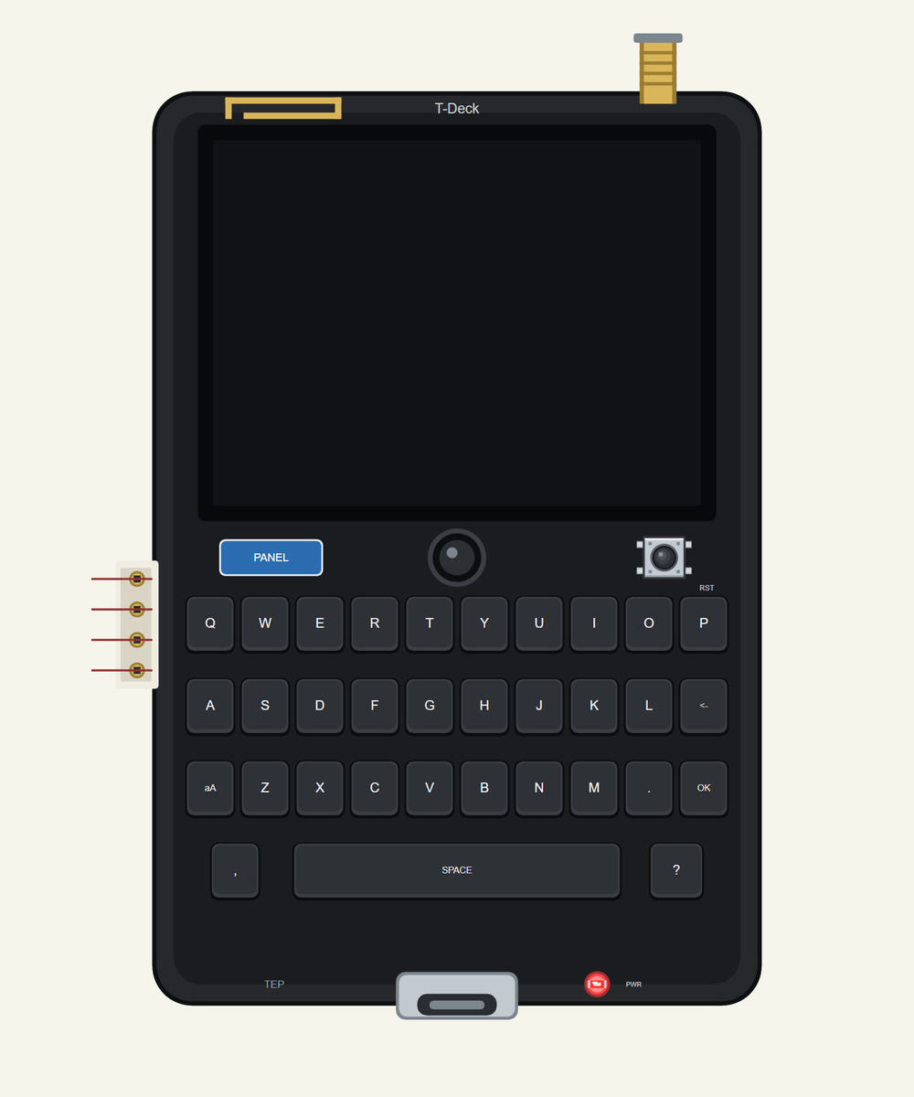
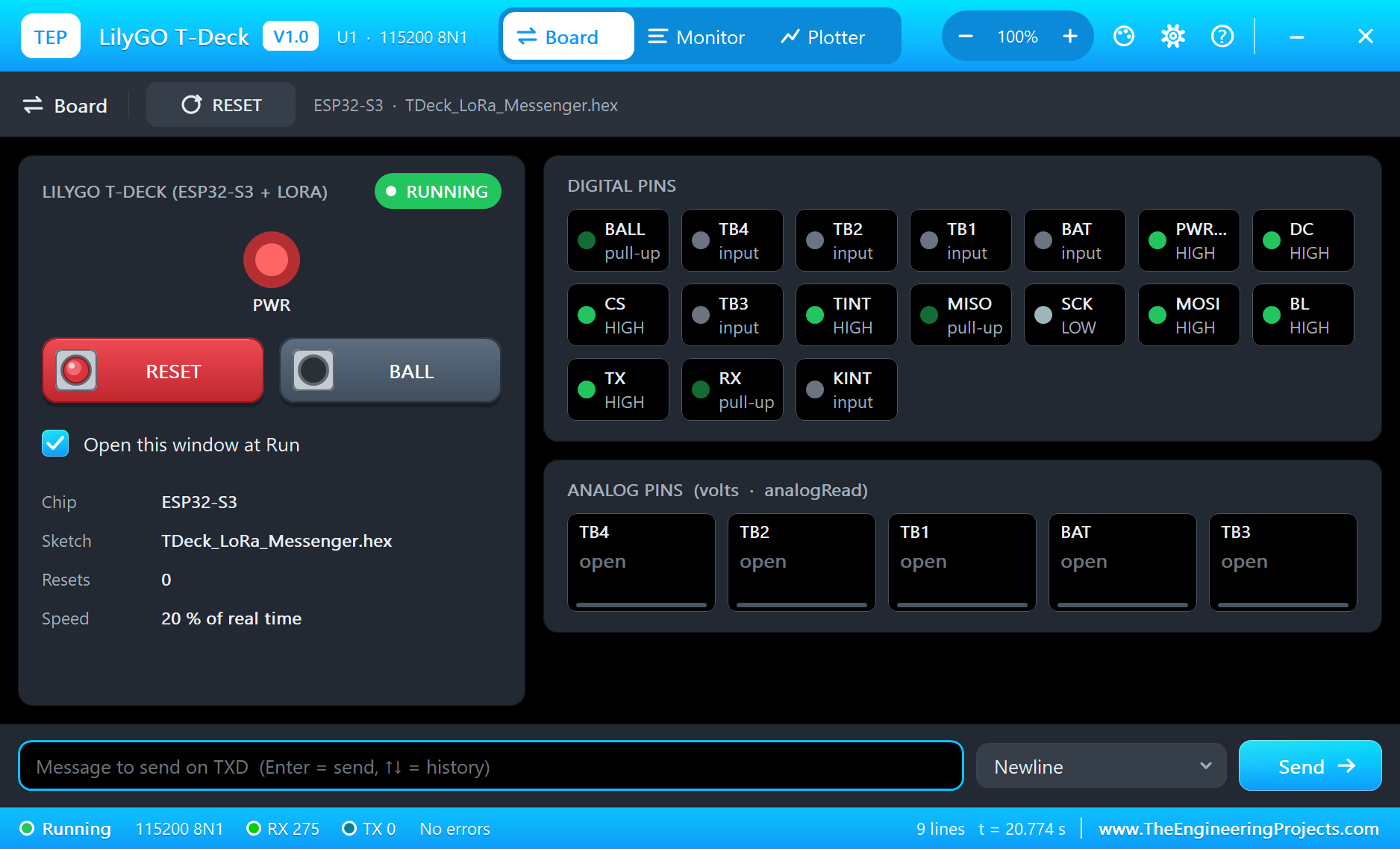
Search T-DECK in Pick Devices; the device is in TEPTDECK.LIB (Microprocessor ICs, ESP32 Boards), with the prefix U. It has two windows: click the USB-C port for the serial monitor, and the blue PANEL pad for the panel. A click on the glass does not open anything, because the glass is the touch screen, and a click on a key types that key. The aA key makes the next letter a capital, and the small arrow is the backspace.
The Pins
| Place | Pins | What the library does with them |
|---|---|---|
| Grove | G43, G44 | Serial TX and RX |
| Grove | 3V3, GND | the supply |
| Inside | 40, 41, 38 | the SPI bus: SCK, MOSI and MISO, shared by the display and the radio |
| Inside | 12, 11, 42 | the display's CS, DC and backlight |
| Inside | 9, 17, 13, 45 | the SX1262: NSS, RESET, BUSY and DIO1 |
| Inside | 16, 46 | the touch's INT and the keyboard's INT |
| Inside | 10 | POWERON, the switch for everything around the processor |
| Inside | 0 | the trackball's click |
The variant uses LilyGO's own names, such as BOARD_TFT_CS, BOARD_POWERON and RADIO_DIO1_PIN, so a sketch written for the real T-Deck reads the same here. The speaker, the microphones, the microSD slot, the battery and the rolling of the trackball are not modelled.
Download LilyGO T-Deck Library for Proteus
Click the button below to download LilyGO-T-Deck-Library-for-Proteus-v1.0.zip (about 3.2 MB, without the source code of the models):
LilyGO T-Deck Library for Proteus V1.0- README.txt: installation, the demo, the pins, the keyboard, the touch, the properties, troubleshooting and the limits.
- Proteus Library Files:
TEPTDECK.LIB. - Proteus Model Files:
TEPNET.DLL. - Arduino Code: the demo sketch and the TEP Boards for Proteus add-on 1.53.0.
- Proteus Simulation: the demo project, its HEX file and a copy of the DLL.
No Proteus yet? Read How to Download and Install Proteus 7 and 8. New to libraries? Follow How to Install a New Library in Proteus.
How to Install LilyGO T-Deck Library for Proteus
- Close Proteus and extract the whole zip file, for example to your Desktop.
- Copy
TEPTDECK.LIBfrom Proteus Library Files into the LIBRARY folder of Proteus. - Copy
TEPNET.DLLfrom Proteus Model Files into the MODELS folder, replacing an older one. - Delete
TEPTDECK.IDXfrom the LIBRARY folder if it is there. - For your own sketches, copy Arduino Code\TEP Boards for Proteus\hardware into your Arduino sketchbook (Documents\Arduino) and restart the Arduino IDE; the board is LilyGO T-Deck (TEP Proteus). Install RadioLib, Adafruit ST7735 and ST7789, Adafruit GFX and Adafruit BusIO from the Library Manager.
- Start Proteus, press P and search for T-DECK.
Demo: a LoRa Messenger
When the mobile network is down, or there was never any coverage to begin with, a phone is not much use. Hikers, farmers and rescue teams all meet this problem, and LoRa is a popular answer. A pair of cheap radios can pass short text messages over kilometres, with no tower, no contract and very little battery. The Meshtastic project has made this idea famous, and the T-Deck is one of the handhelds it supports. Our demo is the same idea at its simplest: two devices, one sketch, and a screen that shows each message.
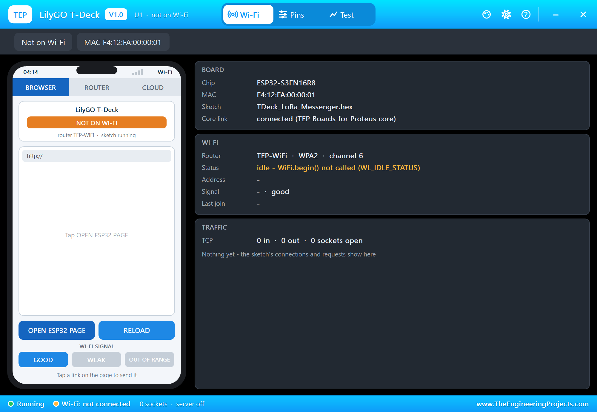
Open LilyGO-T-Deck-LoRa-Messenger.pdsprj. U1 and U2 both run TDeck_LoRa_Messenger.hex, and each one takes its number from the end of its MAC address, so the same HEX file works on both. Their LORADIST property is 1 km. The monitor is the same window as our TEP Serial Monitor Advance for Proteus.
How LoRa Reaches So Far
A normal radio sends each bit as a fixed tone, so noise can easily bury it. LoRa sends each symbol as a chirp: a tone that sweeps across the whole bandwidth, like a slide whistle. The receiver knows the shape of the sweep, so it can stack up the energy of the whole chirp and lift the signal out of the noise. In fact, LoRa can decode a signal that is weaker than the noise itself, which shows up as a negative SNR.
The main setting is the spreading factor. Each step up doubles the length of a symbol, which gives more range and a lower data rate. Our sketch uses the fast end of the scale: 868 MHz, 125 kHz of bandwidth, spreading factor 7, coding rate 4/5 and 14 dBm of power. A short message takes a fraction of a second in the air. That is fine for a chat, and it keeps the channel free for the other radios.
| Setting | In the demo | What it does |
|---|---|---|
| Frequency | 868 MHz | must match the licence-free band of your country |
| Bandwidth | 125 kHz | wider is faster, narrower reaches further |
| Spreading factor | 7 | higher reaches further, and each step takes twice as long |
| Coding rate | 4/5 | extra bits to repair errors |
| Power | 14 dBm | how hard the radio transmits |
A Tiny Protocol
LoRa only moves bytes, so the two T-Decks need to agree on what the bytes mean. A radio link can also lose a packet with no warning, so a message needs an answer before we can call it delivered. Our protocol is four kinds of short text packet. Each one carries the sender's number and a sequence number, and that number is how the sketch finds the right line to turn green:
| Packet | Meaning | Who answers |
|---|---|---|
| M,1,1,Hello | a message from T-Deck 1, number 1 | A |
| A,2,1, | number 1 arrived | nobody |
| P,1,3, | a ping | R |
| R,2,3,-107 | the ping arrived at -107 dBm | nobody |
Sending a Packet
snprintf() builds the text, and radio.transmit() sends it and waits until it has gone. LoRa radios are half duplex, which means they cannot listen while they talk, so startReceive() always follows. Look at the line before it too. The DIO1 pin also rises when a transmission ends, and our first version took that for a new packet and read its own message back. A real T-Deck would do exactly the same, so we clear the flag here:
void sendPacket(char kind, byte seq, const char *text) {
  char packet[48];
  snprintf(packet, sizeof packet, "%c,%u,%u,%s", kind, myId, seq, text);
  const int state = radio.transmit(packet);
  if (state != RADIOLIB_ERR_NONE) { Serial.print(F("transmit failed, code ")); Serial.println(state); }
  radioEvent = false;                                       // DIO1 also rises when a transmission ends: that is not a packet
  radio.startReceive();
}
Receiving a Packet
RadioLib calls onRadio() from an interrupt when a packet arrives. That function only sets a flag, for a good reason: the radio shares the SPI bus with the display, and an interrupt must never step on a screen update in progress. loop() sees the flag and does the real work. It reads the packet, notes the signal strength, and splits the text with sscanf(). The short delay(40) gives the sender a moment to go back to receiving:
void readRadio() {
  if (!radioEvent) return;
  radioEvent = false;
  String packet;
  const int state = radio.readData(packet);
  if (state != RADIOLIB_ERR_NONE) { radio.startReceive(); return; }
  lastRssi = radio.getRSSI();
  const float snr = radio.getSNR();
  drawBand();
  unsigned from = 0, seq = 0;
  char kind = 0;
  char text[32] = "";
  sscanf(packet.c_str(), "%c,%u,%u,%31[^\n]", &kind, &from, &seq, text);
  if (kind == 'M') {
    char line[LINE_CHARS + 1];
    snprintf(line, sizeof line, "%u: %s", from, text);
    addLine(line, ST77XX_WHITE, 0);
    Serial.print(F(">> From ")); Serial.print(from); Serial.print(F(": ")); Serial.print(text);
    Serial.print(F("  (")); Serial.print(lastRssi); Serial.print(F(" dBm, SNR ")); Serial.print(snr, 1); Serial.println(F(" dB)"));
    delay(40);                                              // the sender needs a moment to go back to receiving
    sendPacket('A', seq, "");
  } else if (kind == 'A') {
    Serial.print(F(">> Delivered #")); Serial.println(seq);
    markDelivered(seq);
    radio.startReceive();
  } else if (kind == 'P') {
    char value[8];
    itoa(lastRssi, value, 10);
    delay(40);
    sendPacket('R', seq, value);
  } else if (kind == 'R') {
    char line[LINE_CHARS + 1];
    snprintf(line, sizeof line, "Ping %u: %s dBm", from, text);
    addLine(line, ST77XX_YELLOW, 0);
    Serial.print(F(">> Ping answered by ")); Serial.print(from); Serial.print(F(": they heard us at ")); Serial.print(text); Serial.println(F(" dBm"));
    radio.startReceive();
  } else radio.startReceive();
}
Reading the Keyboard
This is the shortest keyboard driver you will ever see. Every 30 ms the sketch asks the keyboard chip for one byte. Zero means no key. The value 13 is the OK key, and 8 is the backspace. Anything else is added to the line being typed:
void readKeyboard() {
  if (millis() < nextKeys) return;
  nextKeys = millis() + 30;
  Wire.requestFrom(KEYBOARD_ADDR, 1);
  if (!Wire.available()) return;
  const char c = Wire.read();
  if (!c) return;
  if (c == 13) sendTyped();
  else if (c == 8) { if (typedLen) typed[--typedLen] = 0; drawInput(); }
  else if (typedLen < sizeof typed - 1) { typed[typedLen++] = c; typed[typedLen] = 0; drawInput(); }
}
When OK arrives, sendTyped() numbers the message, shows it in cyan and sends it. Cyan means "on its way". The colour changes to green only when the acknowledgement with the same number comes back, so you can see at a glance what really arrived:
void sendTyped() {
  if (!typedLen) return;
  seqNow++;
  char line[LINE_CHARS + 1];
  snprintf(line, sizeof line, "me: %s", typed);
  addLine(line, ST77XX_CYAN, seqNow);
  Serial.print(F(">> Sent #")); Serial.print(seqNow); Serial.print(F(": ")); Serial.println(typed);
  sendPacket('M', seqNow, typed);
  typedLen = 0;
  typed[0] = 0;
  drawInput();
}
Reading the Touch
The GT911 is on the same I2C bus as the keyboard, at address 0x5D. Unlike most I2C parts, it uses 16-bit register numbers, so the sketch writes two bytes, the high one first. The status register 0x814E holds the number of touches, and the X and Y of the first point follow it. Then the sketch writes a zero there, to tell the chip that the point has been read. The INT pin goes LOW while a finger is down, so the bus stays quiet the rest of the time:
bool readTouch(int &x, int &y) {
  if (digitalRead(BOARD_TOUCH_INT) == HIGH) return false;   // INT is LOW while a finger is down
  Wire.beginTransmission(TOUCH_ADDR);
  Wire.write(0x81); Wire.write(0x4E);                       // the status register
  Wire.endTransmission();
  Wire.requestFrom(TOUCH_ADDR, 6);
  const byte status = Wire.read();
  Wire.read();                                              // the point's track id
  const byte xl = Wire.read(), xh = Wire.read(), yl = Wire.read(), yh = Wire.read();
  Wire.beginTransmission(TOUCH_ADDR);
  Wire.write(0x81); Wire.write(0x4E); Wire.write(0);        // clear the status, for the next point
  Wire.endTransmission();
  x = xl | (xh << 8);
  y = yl | (yh << 8);
  return (status & 0x0F) > 0;
}
The touch has one job in this demo. A touch in the top right corner, on the red CLR button, clears the list. wasTouched makes sure that one touch counts once, however long the finger stays down:
void handleTouch() {
  int x, y;
  const bool touched = readTouch(x, y);
  if (touched && !wasTouched) {
    Serial.print(F("Touch at ")); Serial.print(x); Serial.print(F(", ")); Serial.println(y);
    if (x >= 260 && y < 26) {
      lineCount = 0;
      drawLines();
      Serial.println(F(">> Messages cleared"));
    }
  }
  wasTouched = touched;
}
The Message List
The screen shows eight lines, and each line remembers its text, its colour and its sequence number. When the list is full, memmove() slides everything up by one place, like a real chat window. The list lives in a plain array, so nothing is allocated and the memory use stays the same forever:
void addLine(const char *text, uint16_t colour, byte seq) {
  if (lineCount == LINES) { memmove(lines, lines + 1, sizeof(Line) * (LINES - 1)); lineCount--; }
  strncpy(lines[lineCount].text, text, LINE_CHARS);
  lines[lineCount].text[LINE_CHARS] = 0;
  lines[lineCount].colour = colour;
  lines[lineCount].seq = seq;
  lineCount++;
  drawLines();
}
Starting Up
The first line matters most. BOARD_POWERON switches on the power for the display, the radio and the keyboard, and nothing around the processor answers until it goes HIGH. Then come the serial port, the two buses, the display and the radio. tft.init(240, 320) describes the glass, and setRotation(1) turns it to landscape. radio.begin() takes the settings from our table, and the sketch stops with an error code if the chip does not answer:
void setup() {
  pinMode(BOARD_POWERON, OUTPUT); digitalWrite(BOARD_POWERON, HIGH);   // the display, the radio and the keyboard hang on this pin
  Serial.begin(115200);
  Serial.println(F("T-Deck LoRa Messenger - The Engineering Projects"));
  pinMode(BOARD_TOUCH_INT, INPUT);
  pinMode(BOARD_BOOT_PIN, INPUT_PULLUP);
  pinMode(BOARD_TFT_BACKLIGHT, OUTPUT); digitalWrite(BOARD_TFT_BACKLIGHT, HIGH);
  Wire.begin(BOARD_I2C_SDA, BOARD_I2C_SCL);
  SPI.begin(BOARD_SPI_SCK, BOARD_SPI_MISO, BOARD_SPI_MOSI);
  tft.init(240, 320);
  tft.setRotation(1);
  tft.fillScreen(ST77XX_BLACK);
  myId = (byte)(ESP.getEfuseMac() >> 40);
  const int state = radio.begin(868.0, 125.0, 7, 5, RADIOLIB_SX126X_SYNC_WORD_PRIVATE, 14);
  if (state != RADIOLIB_ERR_NONE) { Serial.print(F("SX1262 failed, code ")); Serial.println(state); while (true) delay(10); }
  radio.setPacketReceivedAction(onRadio);
  radio.startReceive();
  Serial.print(F("I am T-Deck ")); Serial.println(myId);
  drawBand();
  drawLines();
  drawInput();
}
Run the Demo
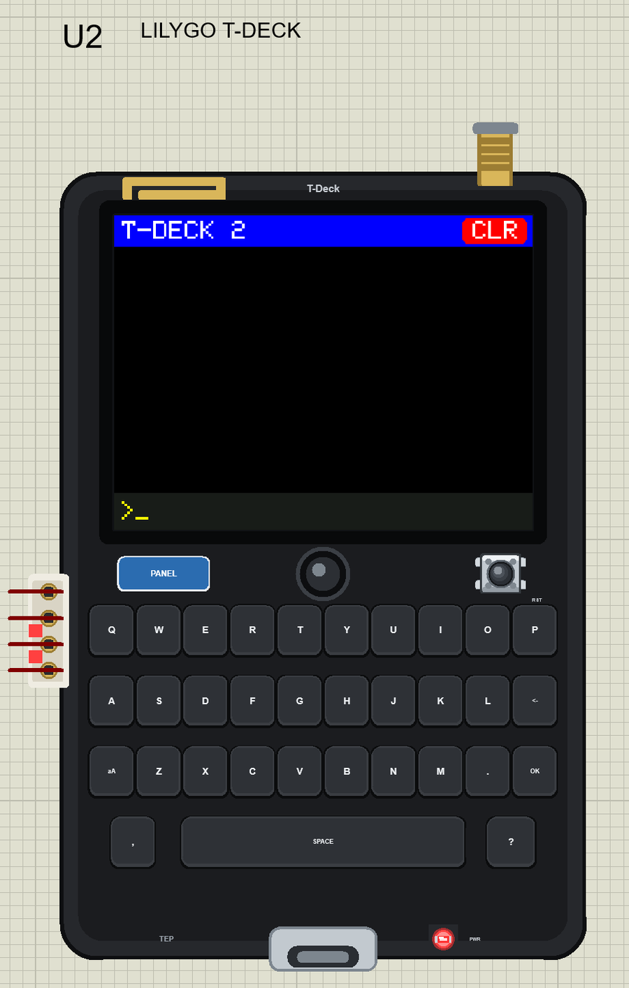
Press Run. Both screens paint a blue band with their number, a red CLR button and an empty prompt, and each monitor greets you:
T-Deck LoRa Messenger - The Engineering Projects
I am T-Deck 1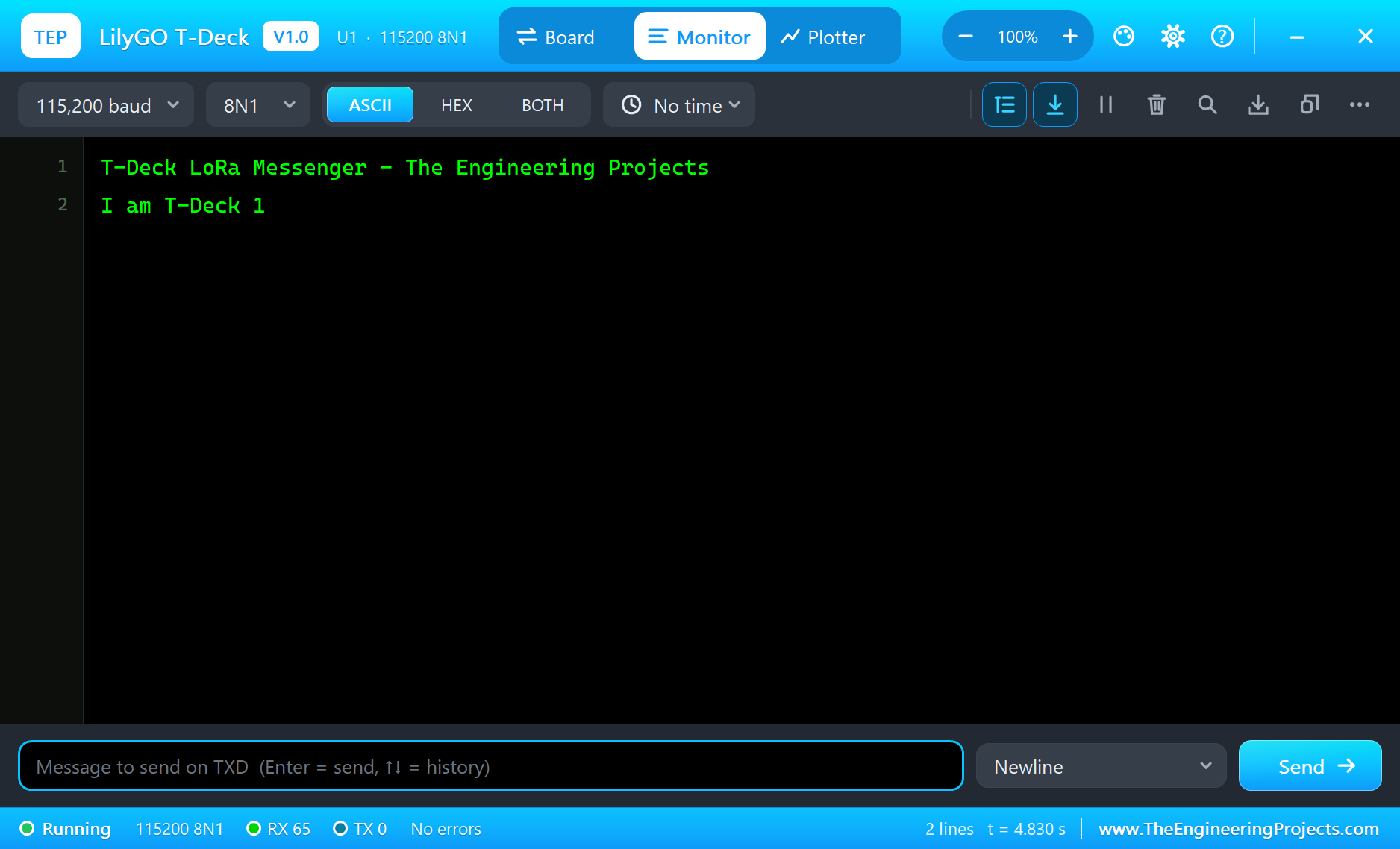
Send a Message
Click the keys on U1 with the mouse. The text grows on the yellow line at the bottom of the screen. We typed "Hello from Deck 1":
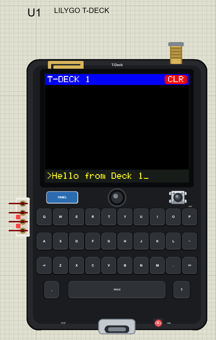
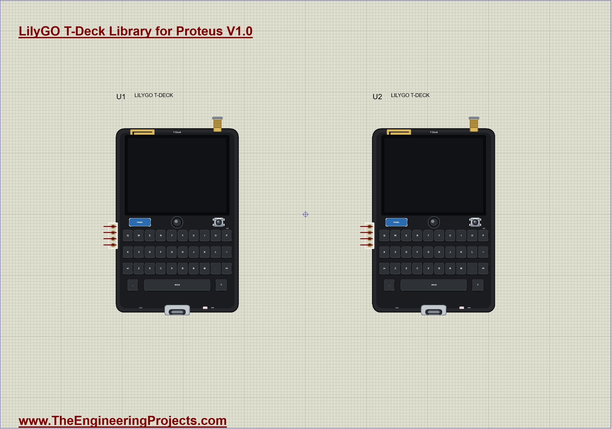
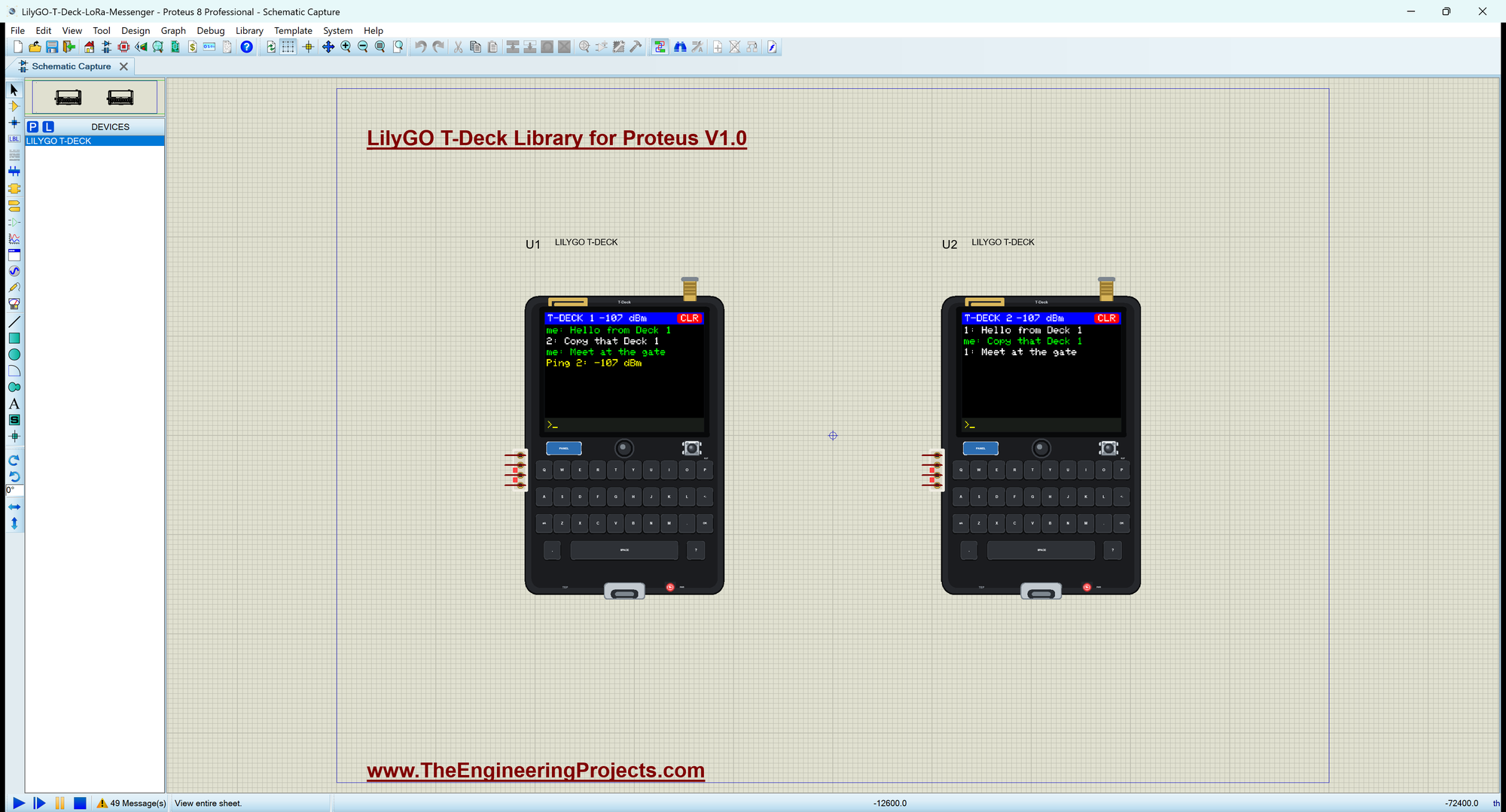
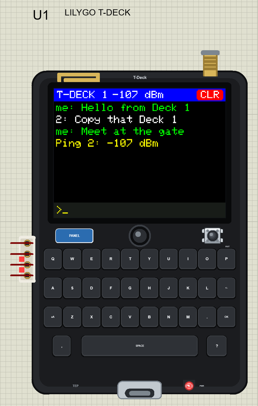
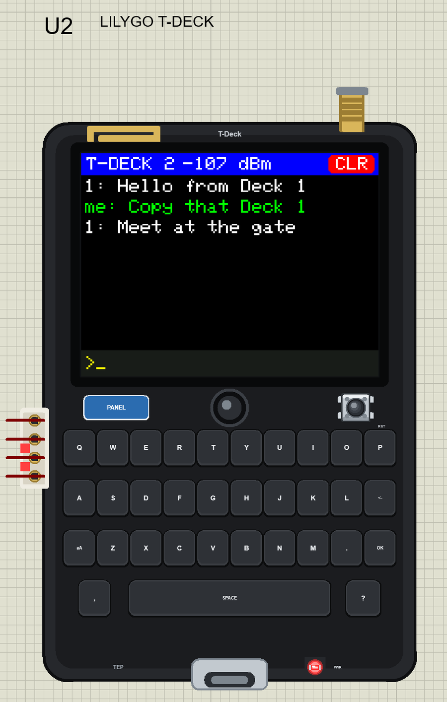
Now click OK. The line jumps into the list in cyan, and U2 shows it a moment later in white, with the sender's number in front. U2 answers by itself, and when that packet reaches U1 the line turns green. Both bands now show the signal strength of the last packet, -107 dBm, and the monitor of U2 adds an SNR of 9.8 dB. That is a healthy link for a distance of 1 km.
Next, answer from U2: type a reply there and click OK. Then send one more line from U1. Each T-Deck keeps its own count, so U2's first message is also number 1. The complete circuit looks like this while it runs:
Ping the Other T-Deck
Click the trackball on U1. It sends a ping, and U2 sends back the strength at which it heard that ping. The answer lands in the list in yellow. This tells you about the path in the other direction, which is useful on real links, because two radios rarely hear each other equally well. The monitor of U1 has followed the whole chat:
>> Sent #1: Hello from Deck 1
>> Delivered #1
>> From 2: Copy that Deck 1  (-107 dBm, SNR 9.8 dB)
>> Sent #2: Meet at the gate
>> Delivered #2
>> Ping #3
>> Ping answered by 2: they heard us at -107 dBm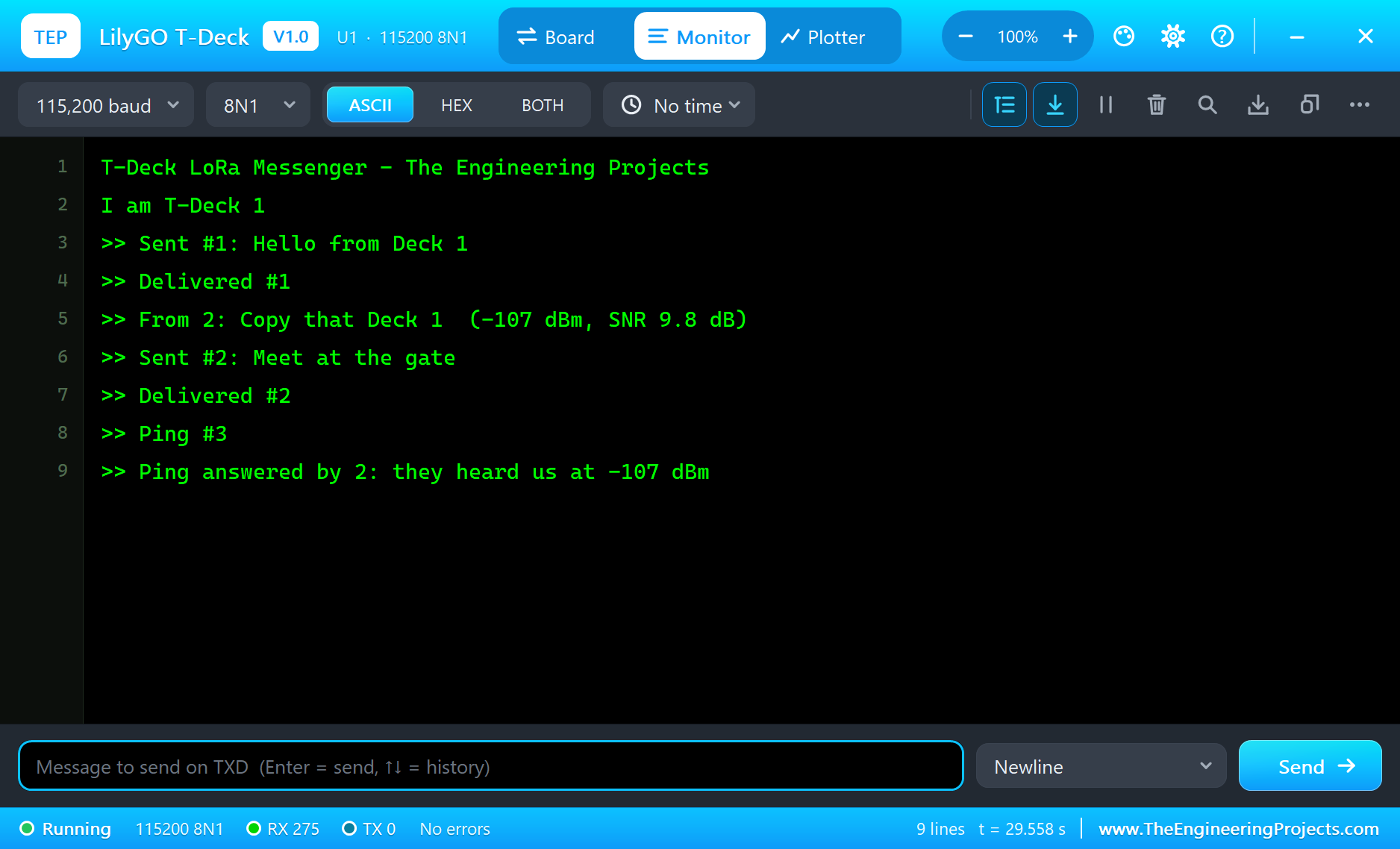
And here is U2, with the same conversation from its side:
>> From 1: Hello from Deck 1  (-107 dBm, SNR 9.8 dB)
>> Sent #1: Copy that Deck 1
>> Delivered #1
>> From 1: Meet at the gate  (-107 dBm, SNR 9.8 dB)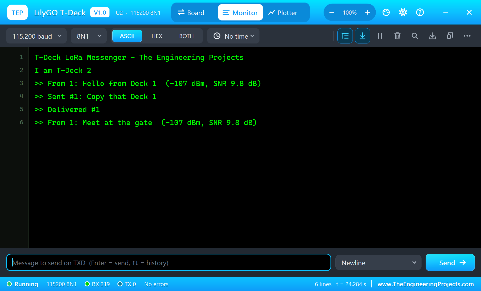
Clear the Screen
Finally, click CLR on the glass of U2. The GT911 reports the touch, the monitor prints the place, and the list empties. U1 keeps its own list, because the two T-Decks share nothing except the air:
Touch at 290, 12
>> Messages cleared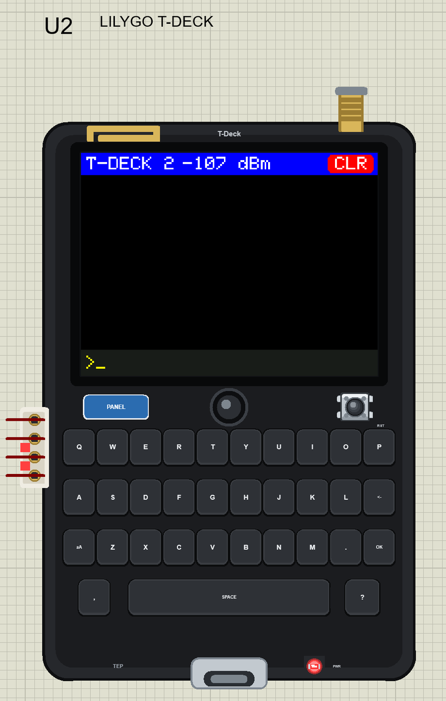
Try It Yourself
- Change the LORADIST property of both T-Decks and watch the RSSI on the band.
- Add a third T-Deck to the sheet, and think about what happens when two of them answer at the same moment.
- Try spreading factor 9 on both boards, and compare how long a message takes.
- Give each line the time it arrived, using
millis().
Ideas to Extend the Messenger
- Resend a message by itself if no acknowledgement comes back within two seconds.
- Let each T-Deck forward the messages it hears, for a small mesh network.
- Use the Wi-Fi of one T-Deck as a gateway, and post what it receives to a web page.
- Add a simple password to the packets, so that only your own group can read them.
Your Own Sketches
Write the sketch in the Arduino IDE with the board LilyGO T-Deck (TEP Proteus), use Sketch > Export Compiled Binary and set the part's PROGRAM property to the .hex. The pin names are LilyGO's, so a sketch moves easily to the real product with Espressif's "esp32" package. If you like long-range boards, our LilyGO T-Beam Supreme Library for Proteus adds GPS and our Heltec WiFi LoRa 32 V3 Library for Proteus is the small one, and every one of them talks to the T-Deck. For a touch screen without a radio, see our M5Stack Core2 Library for Proteus.
Things to Know Before Using a Real T-Deck
- POWERON comes first: set GPIO 10 HIGH before anything else, or the display, the radio and the keyboard will not answer.
- Fit the antenna first: a LoRa radio that transmits with no antenna can damage itself.
- Pick the right band: buy the version for your country, because the licence-free LoRa frequencies differ from place to place.
- Mind the shared bus: the display, the radio and the microSD slot all use one SPI bus, so set every chip-select HIGH before you start any of them.
- LoRa is optional: some T-Decks are sold without the radio, so check before you order.
- Messages are not private: this demo sends plain text, and any radio with the same settings can read it.
Properties of the LilyGO T-Deck
| Property | What it does |
|---|---|
| PROGRAM | the sketch: a .hex from TEP Boards for Proteus (board "LilyGO T-Deck") |
| LORADIST | the distance to the other LoRa boards, from 10 m to 20 km |
| WIFISSID, WIFIPASS | the router in range (TEP-WiFi, 12345678) |
| MONITOR, BAUD, AUTOOPEN | the built-in serial monitor: on, its baud rate (115200), open at Run |
Troubleshooting
- The display stays black: set
BOARD_POWERONHIGH first, then callSPI.begin()with the three bus pins andtft.init(240, 320). - RadioLib fails with -2: use
new Module(RADIO_CS_PIN, RADIO_DIO1_PIN, RADIO_RST_PIN, RADIO_BUSY_PIN). - No packets arrive: both boards need the same frequency, bandwidth, spreading factor and sync word, and
startReceive()again after each send. - A packet appears after every send: DIO1 also rises when a transmission ends, so clear your flag as
sendPacket()does. - The keys or the touch do nothing: call
Wire.begin(BOARD_I2C_SDA, BOARD_I2C_SCL), and setBOARD_TOUCH_INTas an input. - A number goes wrong above 32767: int is 16 bits in the simulation - use long.
Limitations of the Simulation
- Your sketch gets 8 KB of RAM in the simulation, and there are no FreeRTOS tasks and no second core. A heavy graphics library such as LVGL does not fit.
- The speaker, the microphones, the microSD slot, the battery, the keyboard's light, the rolling of the trackball and Bluetooth are not modelled.
- LoRa works between the TEP LoRa boards of one design. Dragging on the glass is not followed.
- LilyGO and T-Deck are names of LilyGO, ESP32 of Espressif Systems and LoRa of Semtech; this library is not made or endorsed by them or by Labcenter.
- Tested in Proteus 8.5 in October 2026 (the demo as shipped, about 30 s of simulation). Proteus 7 is not supported.
So, that was all about the LilyGO T-Deck Library for Proteus. I hope it helps you design your own off-grid gadgets before you buy one - the keyboard, the touch screen, the trackball and LoRa in one simulation. If you have any questions, ask in the comments and I will help you out. Till the next tutorial, take care and have fun!

Comments
0