


3.5 inch TFT LCD Shield Library for Proteus V1.0 (ILI9486 Touch)


Hello friends, I hope you all are doing great. Today, I am going to share the new 3.5" TFT LCD Shield Library for Proteus V1.0. When the 2.4" screen gets too small for your menus, meters and buttons, the next step on an Arduino UNO is the red 3.5 inch TFT LCD shield: 480 x 320 pixels, twice the pixels of the 2.4" shield, the same 65,536 colours and the same resistive touch screen, and it still plugs straight on the UNO. With this 3.5" TFT LCD Shield Library for Proteus, you can design a full-size touch interface, test it in the simulation and see exactly what the real shield would show, pressing the glass with your mouse.
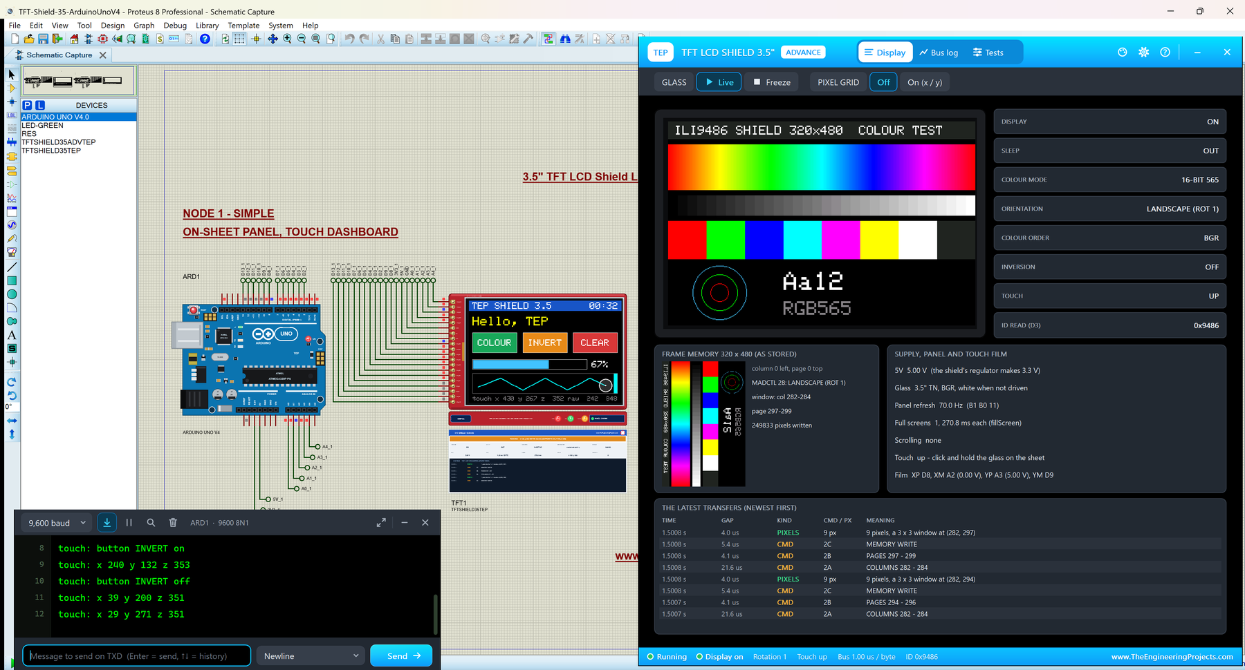
Inside the shield sits the ILI9486 controller, and that is what our own model simulates, written from the ILI9486 datasheet: the 320 x 480 frame memory, the 8-bit parallel bus, the register reads that MCUFRIEND_kbv uses to recognise the chip, the rotations and the start-up waits. The touch film is a real resistor network in the analog simulation on the shield's shared pins, so analogRead() sees what it would see on the bench. There are two devices, Simple with a live STATUS panel and Advance with a pop-up window and five test tools, and the demo runs on our Arduino UNO V4.0 with its serial monitor built into the board.
NOTICE: We built this library right after our 2.4" shield, and the bigger glass taught us something new: a 3.5" screen has twice the pixels on the same 8-bit bus, so every design decision about what to redraw matters twice as much. We modelled the ILI9486 from its datasheet, kept the touch film in the analog simulation and tested the whole shield with the real MCUFRIEND_kbv and Adafruit TouchScreen libraries. It took our team a lot of hard work. Your feedback is the fuel that keeps us going, so please tell us what you think in the comments below or in the LCD Library board of our forum. And if our free libraries help you, you can buy us a coffee. So, let's get started with the 3.5" TFT LCD Shield Library for Proteus V1.0:
What is a 3.5" TFT LCD Shield?
The 3.5" TFT LCD shield is a colour display board made to sit on an Arduino UNO (or a Mega 2560). Its glass is almost as large as the board itself: 480 x 320 pixels on a 73.44 x 48.96 mm picture, with a resistive touch film on top and a micro SD card slot underneath. Like the smaller shields, it is driven over an 8-bit parallel bus, eight data lines plus five control lines that land on D2 - D9 and A0 - A4 of the UNO, and the touch film shares four of those pins.
The board is sold in two versions: MAR3501 with the touch film and MAR3502 without it (lcdwiki's names); this library is the version with touch. And like the 2.4" boards, the same red PCB is made with different controllers. The common one is the ILI9486, but you also find ILI9488, ST7796 and ILI9481 boards. That is why the MCUFRIEND_kbv library reads the controller's ID first: our model answers 0x9486.
The 3.5" Shield Next to the 2.4" Shield
| 2.4" shield | 3.5" shield (this library) | |
|---|---|---|
| Controller | ILI9341 | ILI9486 |
| Pixels | 320 x 240 (76,800) | 480 x 320 (153,600) |
| Picture | 48.96 x 36.72 mm | 73.44 x 48.96 mm |
| Board | 72.2 x 52.7 mm | 85.49 x 55.63 mm |
| Bytes in a full screen (16-bit) | 153,600 | 307,200 |
| A full screen on an UNO (this model) | about 135 ms | about 270.8 ms |
| Pins and touch film | the same 20 pins, XP D8, YM D9, XM A2, YP A3 | the same |
Terms You Will See in This Article
| Term | Meaning |
|---|---|
| ILI9486 | The 320 x 480 TFT controller of the shield, with its own frame memory |
| readID() | MCUFRIEND_kbv's function that reads the controller's ID over the data lines |
| LCD_RS / LCD_WR | Command or data, and the write strobe that latches a byte |
| FRS | The ILI9486's frame-rate setting: a table from 28 to 117 Hz, 70 Hz by default |
| RGB565 | A colour in 16 bits; two bytes a pixel on the 8-bit bus |
| Raw x / y / z | What TouchScreen's getPoint() reads from the film (0 - 1023) and the pressure |
The ILI9486 Inside: What Changes From the 2.4" Shield
On the bus, the ILI9486 talks exactly like the ILI9341: LCD_CS low, LCD_RS low for a command and high for data, a byte latched on the rising edge of LCD_WR, and answers clocked out with LCD_RD. MCUFRIEND_kbv sends every command with a 00 NOP in front of it, reads register D3 and gets 00 94 86, and then runs its ILI9486 start-up: power control C0, C1, C2, VCOM C5, the display function B6, the gamma curves E0 and E1, then sleep out, 16-bit colour and display on.
The differences are in the details, and the model follows the datasheet in each one. The frame memory is 320 columns by 480 pages. The display function B6 (02 02 3B) sets 480 lines and the scan direction, but unlike the ILI9341 it has no REV bit, so only the inversion commands (21 / 20) can invert the colours. The panel's own refresh comes from the FRS table of command B1, from 28 to 117 Hz, and MCUFRIEND keeps the default of 70 Hz. The write cycle is the same 66 ns as the ILI9341, far below what an UNO can produce, so the AVR's code is always the bottleneck.
And then there is the size. A full screen is now 153,600 pixels, 307,200 bytes on the 8-bit bus. On an UNO a fillScreen() takes about 270.8 ms, which you can see as a wipe across the glass. A good 3.5" sketch therefore draws its background once and then only what changes: a digit, a bar, a button.
What's New in 3.5" TFT LCD Shield Library for Proteus V1.0
- The 3.5" UNO shield at its real size: 85.49 x 55.63 mm with the 480 x 320 glass along the board, the 20 header pins in the shield's own order and the micro SD slot.
- Our ILI9486 model from the datasheet: the 320 x 480 x 18-bit frame memory, MIPI commands, the rotations and colour order, 16 and 18-bit colour, inversion, idle mode, scrolling, the FRS frame rate and the waits.
- readID() and register reads on the data lines: 0x9486, the power mode, MADCTL, the pixel format.
- The touch film in the analog simulation, read with
analogRead()through the shared pins A2 / A3, including the 20 ohm drive of the AVR's pins. - Touch with the mouse: click, hold and drag on the glass.
- The white screen and its causes on the STATUS panel and in the test tools.
- Five test tools on the Advance device, with the 480 x 320 redraw costs in the Speed tool.
- A 480 x 320 touch demo on our Arduino UNO V4.0: big buttons, a slider, a paint strip and a calibration screen.
- A compact package: about 1.34 MB, without the C++ source code.
3.5" TFT Shield Simple vs Advance
| Simple | Advance | |
|---|---|---|
| Device | TFTSHIELD35TEP | TFTSHIELD35ADVTEP |
| On the schematic | The shield + the TFT SHIELD STATUS panel | The shield only |
| Status | Banner, 10 readouts, the last 6 transfers | A pop-up window: Display, Bus log, Tests |
| Test tools | - | Init check, 8-bit bus, Speed, Pixels, Touch |
Download 3.5" TFT LCD Shield Library for Proteus
Click the button below to download TFT-LCD-Shield-3.5-inch-Library-for-Proteus-v1.0.zip (about 1.34 MB, without the C++ source code):
3.5 inch TFT LCD Shield Library for Proteus V1.0- README.txt: the devices, installation, the demo, wiring, the test tools, calibration and real hardware.
- Proteus Library Files:
TEPTFTSHIELD35.LIBandArduinoV4TEP.LIBfrom our Arduino Library for Proteus V4.0. - Proteus Model Files:
TEPTFTSHIELD35.DLLandTEPARDUINO.DLL. - Proteus Simulation:
TFT-Shield-35-ArduinoUnoV4.pdsprj,TFT_Shield_35_Touch_Demo.hexand copies of both DLLs. - Arduino Code:
TFT_Shield_35_Touch_Demo.ino(needs "MCUFRIEND_kbv", "Adafruit GFX Library" with Adafruit BusIO, and "Adafruit TouchScreen" from the Library Manager).
No Proteus yet? Read How to Download and Install Proteus 7 and 8. New to libraries? Follow How to Install a New Library in Proteus.
How to Install 3.5" TFT LCD Shield Library for Proteus
- Close Proteus and extract the whole zip file, for example to your Desktop.
- Copy the two files from Proteus Library Files into the LIBRARY folder of Proteus (usually
C:\Program Files (x86)\Labcenter Electronics\Proteus 8 Professional\LIBRARY). - Copy
TEPTFTSHIELD35.DLLandTEPARDUINO.DLLfrom Proteus Model Files into the MODELS folder. - Delete
TEPTFTSHIELD35.IDXfrom the LIBRARY folder if there is one. - Start Proteus, press P and search for SHIELD 3.5.
Tip: the 3.5" library has its own file names, so it lives happily next to our 2.4" shield library. Keep the Proteus Simulation folder together: the project needs its .hex file and the DLLs beside it. Tested in Proteus 8.5; Proteus 7 is not supported.
The 3.5" TFT LCD Shield in Proteus
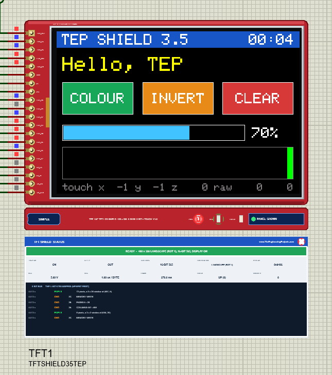
The part is drawn at the shield's real size. The glass covers almost the whole board, leaving only the strip with the 20 pins on the left, so this time the TEP additions moved to the TEP strip under the board: the SIMPLE / ADVANCE badge, the title, the PWR, BUS and TOUCH LEDs and the panel button. A real shield has none of them. The glass lies along the board, so setRotation(1) is the upright 480 x 320 picture.
Pinout
| Shield pin | Function | Arduino UNO |
|---|---|---|
| LCD_RST | Hardware reset, active low | A4 |
| LCD_CS | Chip select (and YP of the film) | A3 |
| LCD_RS | Command / data (and XM of the film) | A2 |
| LCD_WR | Write strobe | A1 |
| LCD_RD | Read strobe | A0 |
| GND / 5V / 3V3 | Ground and supply | GND / 5V / 3.3V |
| LCD_D0, LCD_D1 | Data bits 0 and 1 (and XP, YM of the film) | D8, D9 |
| LCD_D2 - LCD_D7 | Data bits 2 - 7 | D2 - D7 |
| SD_SS, SD_DI, SD_DO, SD_SCK | The micro SD card (not simulated in V1.0) | D10 - D13 |
| Property | Values | What it does |
|---|---|---|
| PANEL | OPEN (default), CLOSED | Simple only: the STATUS panel at the start |
Touching the 3.5" Glass
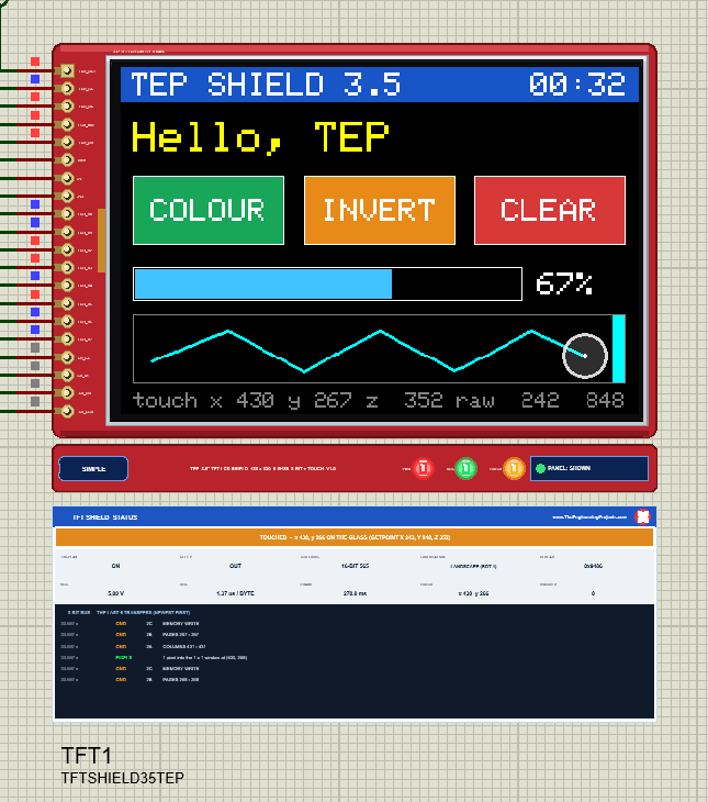
Your mouse is the finger: press the left button on the glass and hold it, move to slide, release to lift. The model connects the film's two resistive plates at that point, and when TouchScreen drives one plate and reads the other with analogRead(), it reads the voltage of the point you hold. On this film the raw values run from about 110 to 910 across the short side and 85 to 935 along the long side, with a pressure of about 350.
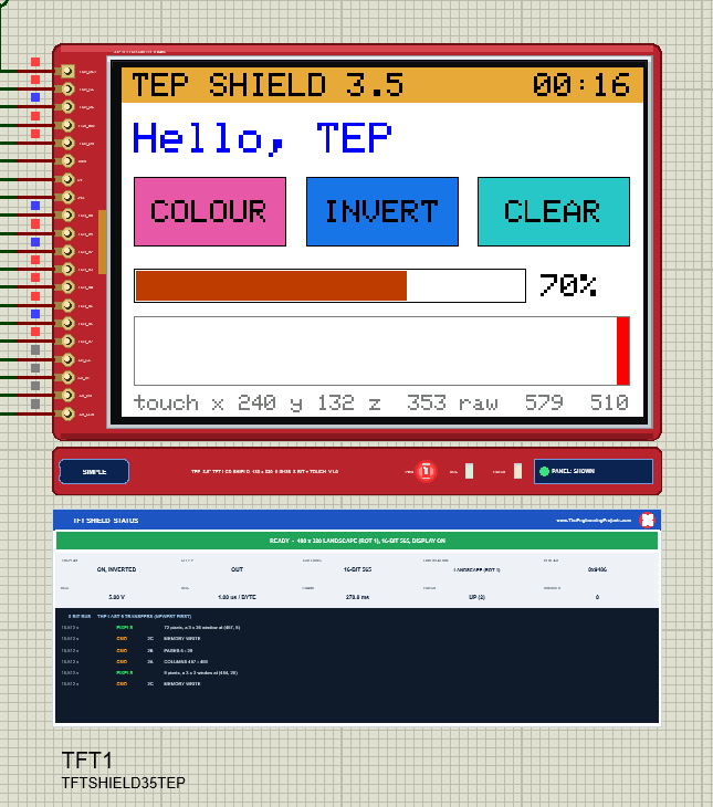
The bigger glass makes a touch interface easier to use: the demo's buttons are 140 x 64 pixels, a size a real fingertip hits without trouble. Each button acts once per press, the slider follows the finger and the paint strip joins the touch points into a line.
Calibrating the 3.5" Touch Screen
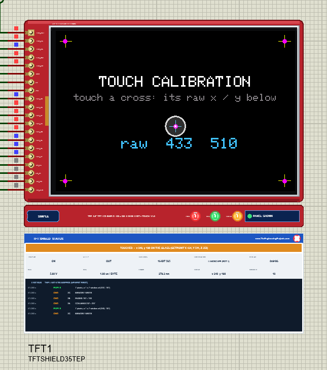
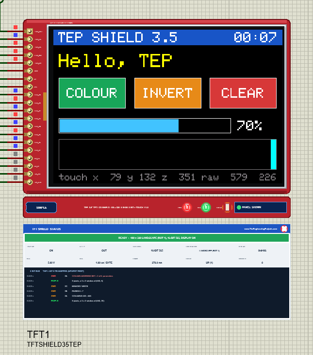
No two touch films read the same, so a sketch needs the raw values at the glass edges: the TS_MINX / TS_MAXX / TS_MINY / TS_MAXY of the demo. Type CAL in the monitor and touch the crosses: the values in the corners are what you put in your sketch. On this model they are 110 / 910 and 85 / 935. Remember that the film's x runs across the short side: in rotation 1 the screen x comes from the raw y.
Designing a 480 x 320 Screen
A 3.5" screen invites a richer layout, and the demo shows a few habits that keep it fast. Text is drawn with a background colour, so the clock's digits overwrite the old ones without any fillRect. The slider redraws only the part that changes. The touch status line is limited to five updates a second while the finger moves. With these habits, the dashboard reacts at once even though a full redraw would take a quarter of a second.
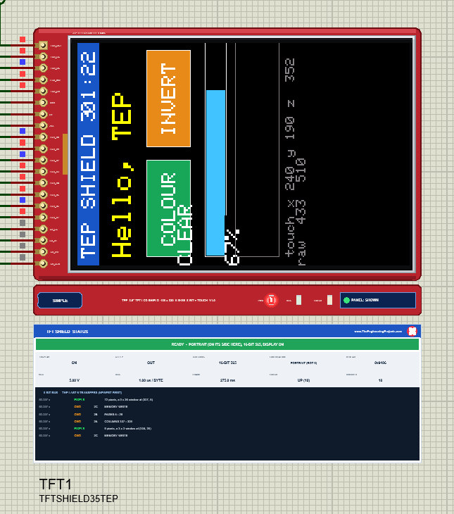
setRotation() works as on every MIPI controller: rotations 0 and 2 are portrait (320 x 480), 1 and 3 landscape (480 x 320), and 1 is upright on this shield. The touch film does not rotate with the picture, so the demo's toScreen() maps the raw values for all four rotations.
The White Screen on a 3.5" Shield
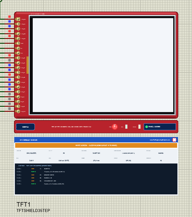
A TFT glass that is not driven lets the backlight through: it is white. On a 3.5" shield that is the picture you get before the sketch initialises the controller, while it sleeps, while its display is off, and when the sketch runs the wrong start-up for the controller on the board. That last case is common with 3.5" shields, because the same board comes with different chips: tft.begin(tft.readID()) picks the right one, a fixed ID may not.
The model shows the same, and the STATUS panel names the reason: NOTHING ON THE BUS YET, STILL IN SLEEP, SLEEP IN, DISPLAY OFF, or STILL ASLEEP when SLEEP OUT came too early after a reset. A wrong colour order has its own banner, RED / BLUE SWAPPED.
3.5" TFT Shield Simple: The STATUS Panel
Under the Simple device a live TFT SHIELD STATUS panel shows the banner (READY, TOUCHED with the point, or the problem), ten readouts (DISPLAY, SLEEP, COLOURS, ORIENTATION, ID READ, VCC, BUS, FRAME, TOUCH, IGNORED) and the last six transfers. The red X closes it; PANEL on the strip opens it again.
3.5" TFT Shield Advance: The Pop-Up Window
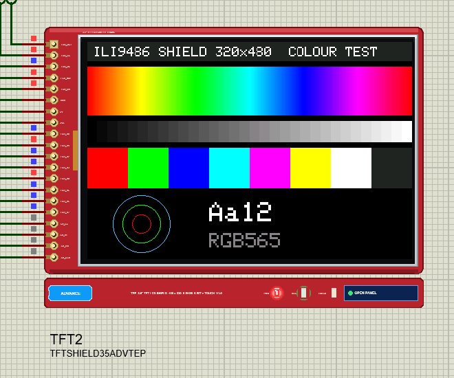
The Advance device keeps only the shield on the schematic; at Run it opens a pop-up window with three pages and the look of our serial monitor.
The Display Page
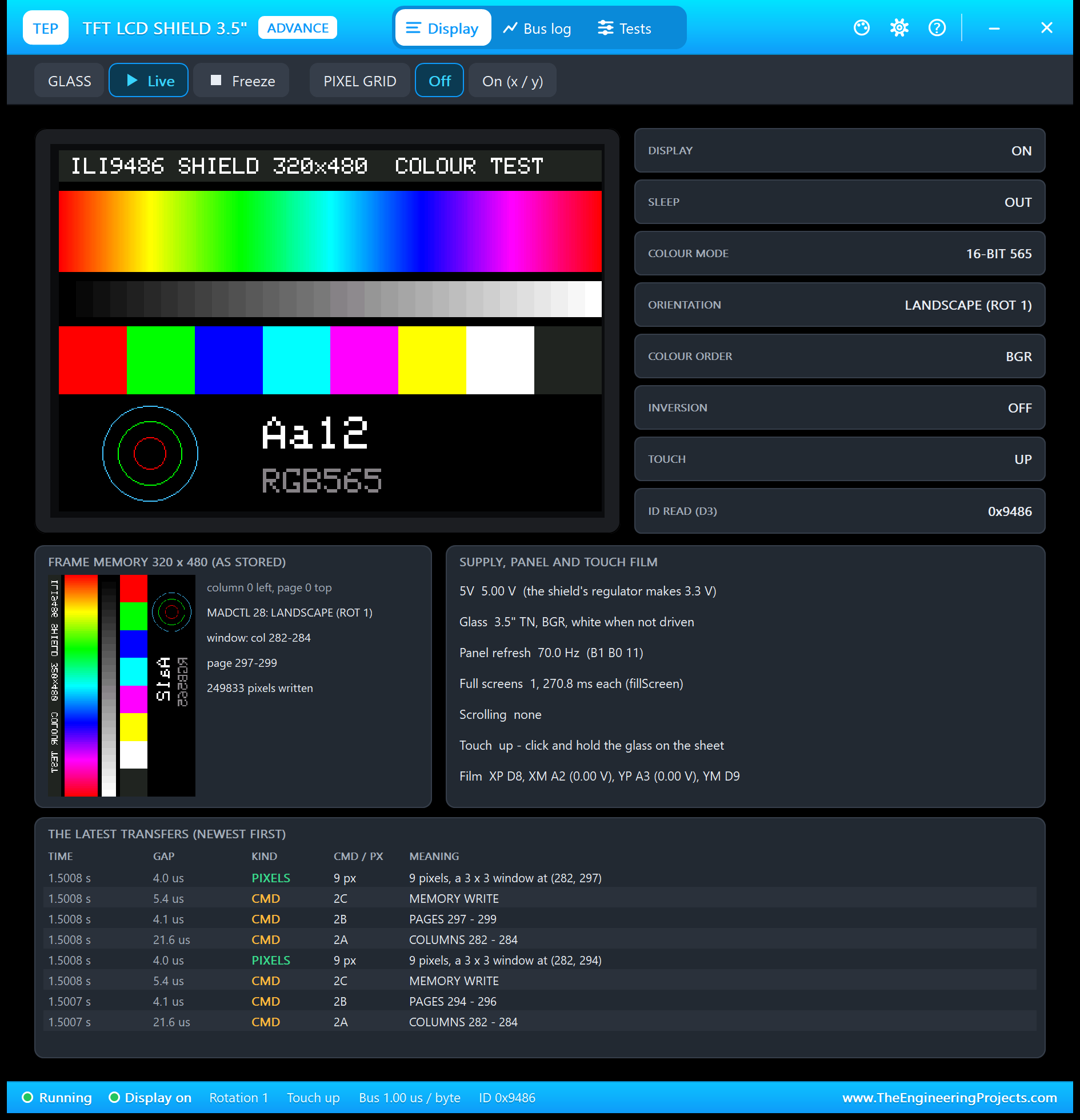
The tiles read the ILI9486: display, sleep, colour mode, orientation, colour order, inversion, touch and the ID readID() got. The frame memory card shows the memory as the controller stores it, 320 columns by 480 pages, turned against the landscape glass.
The Bus Log Page
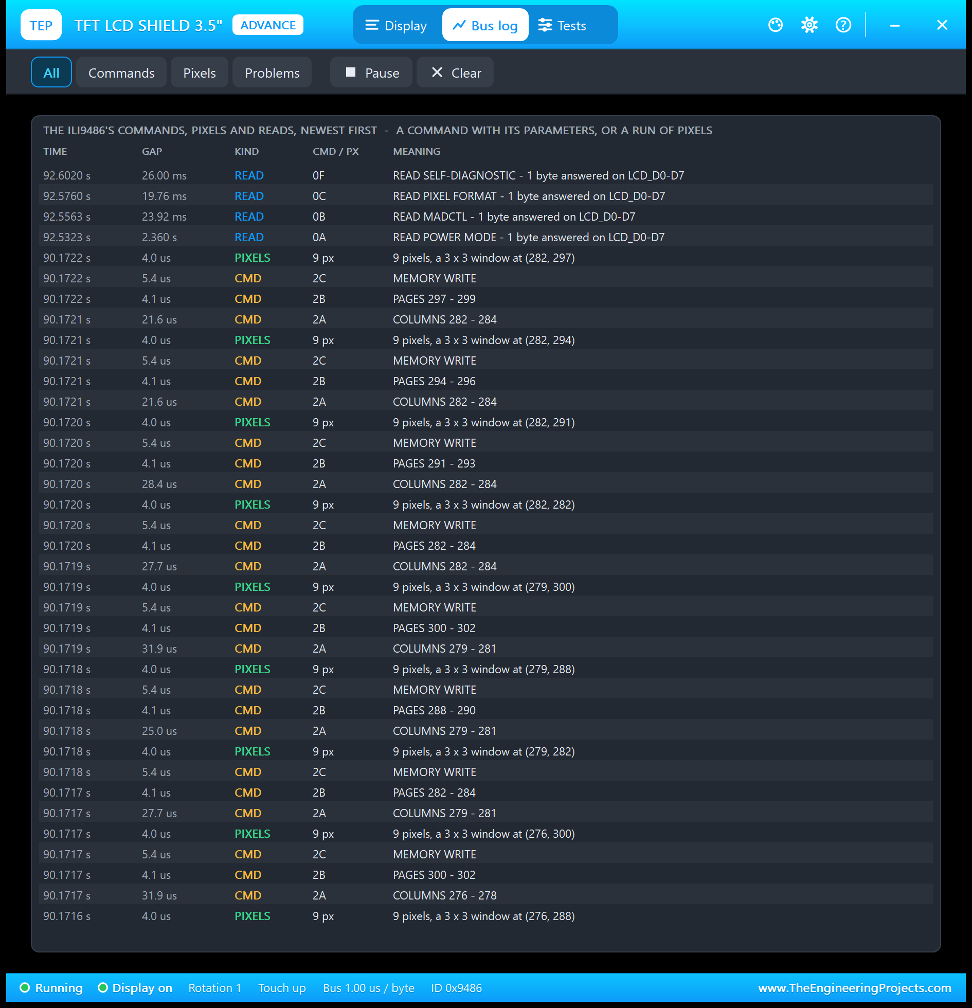
Every transfer with its time and meaning; the filters show only commands, only pixels or only problems.
Five Test Tools for the 3.5" Shield
1. Init Check
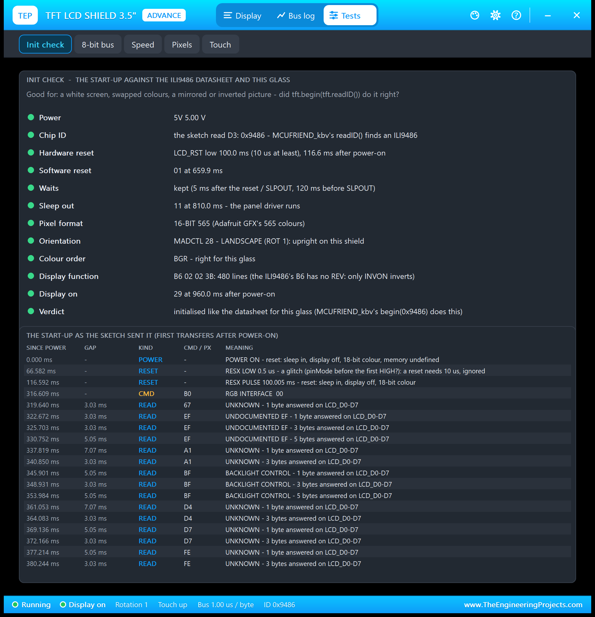
The start-up against the ILI9486 datasheet: the supply, the ID, the hardware and software reset, the datasheet's waits, SLEEP OUT, the pixel format, the orientation, the colour order, the display function and DISPLAY ON, then the start-up as the sketch sent it, readID()'s probes first.
2. 8-Bit Bus
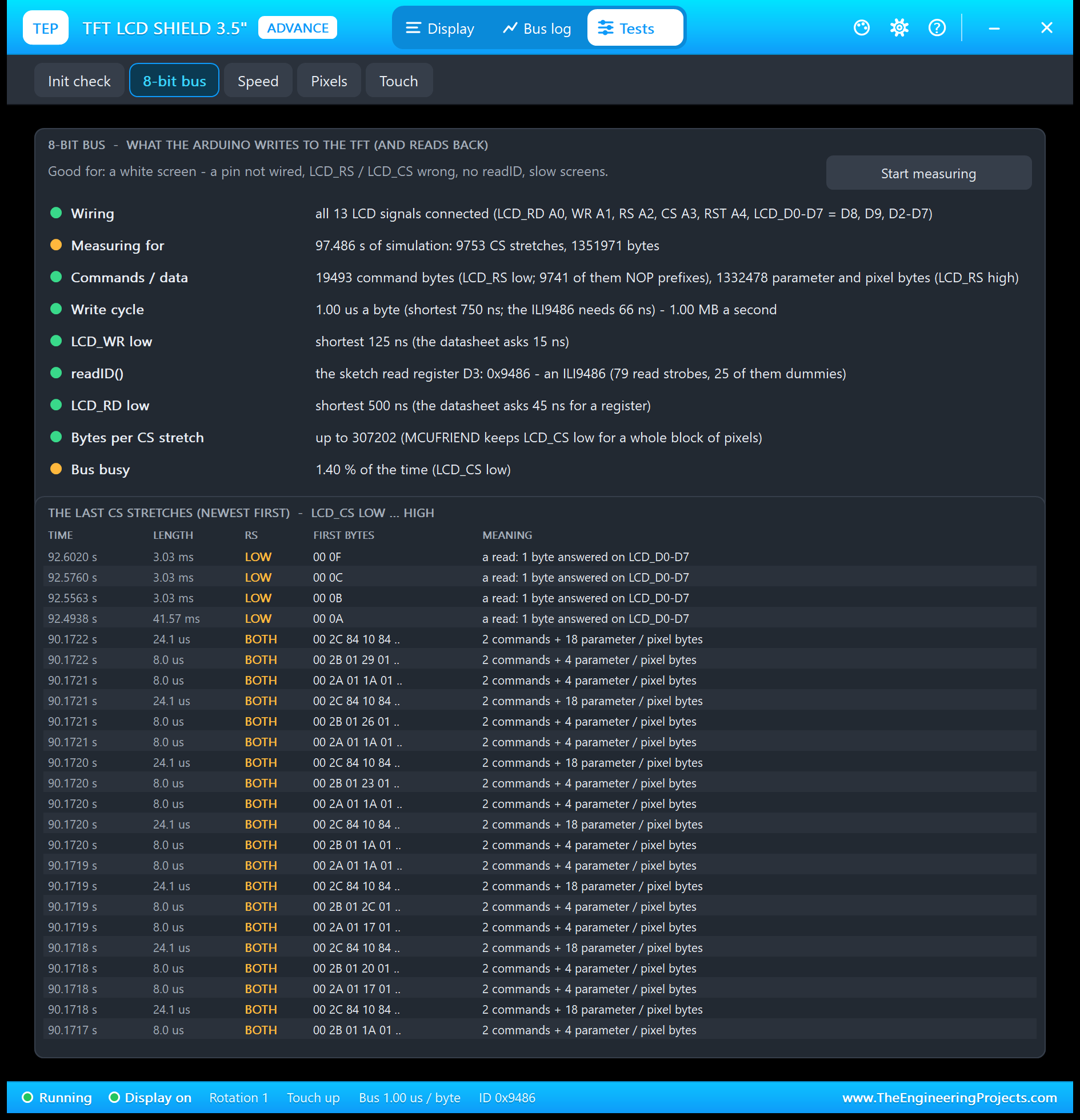
Good for a white screen or a wrong ID: the wiring, the command and data bytes, the write cycle (the ILI9486 takes 66 ns, an UNO about 1 us), the read strobes of readID(), the longest LCD_CS-low stretch - about 307,200 bytes for one fillScreen - and the latest stretches with their first bytes.
3. Speed
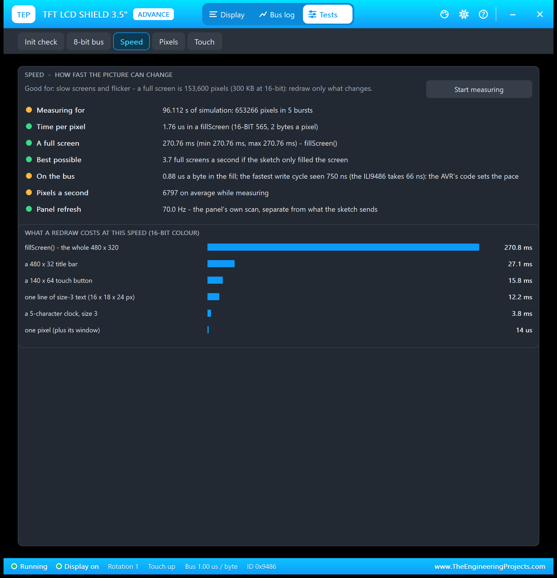
The time per pixel is the same as on the 2.4" shield (1.76 us in a fill), but there are twice as many pixels, so a full screen takes about 270.8 ms. The table below the measurements makes the design rule concrete: a 140 x 64 button costs about 16 ms, a clock about 4 ms, a full screen more than a quarter of a second.
4. Pixels
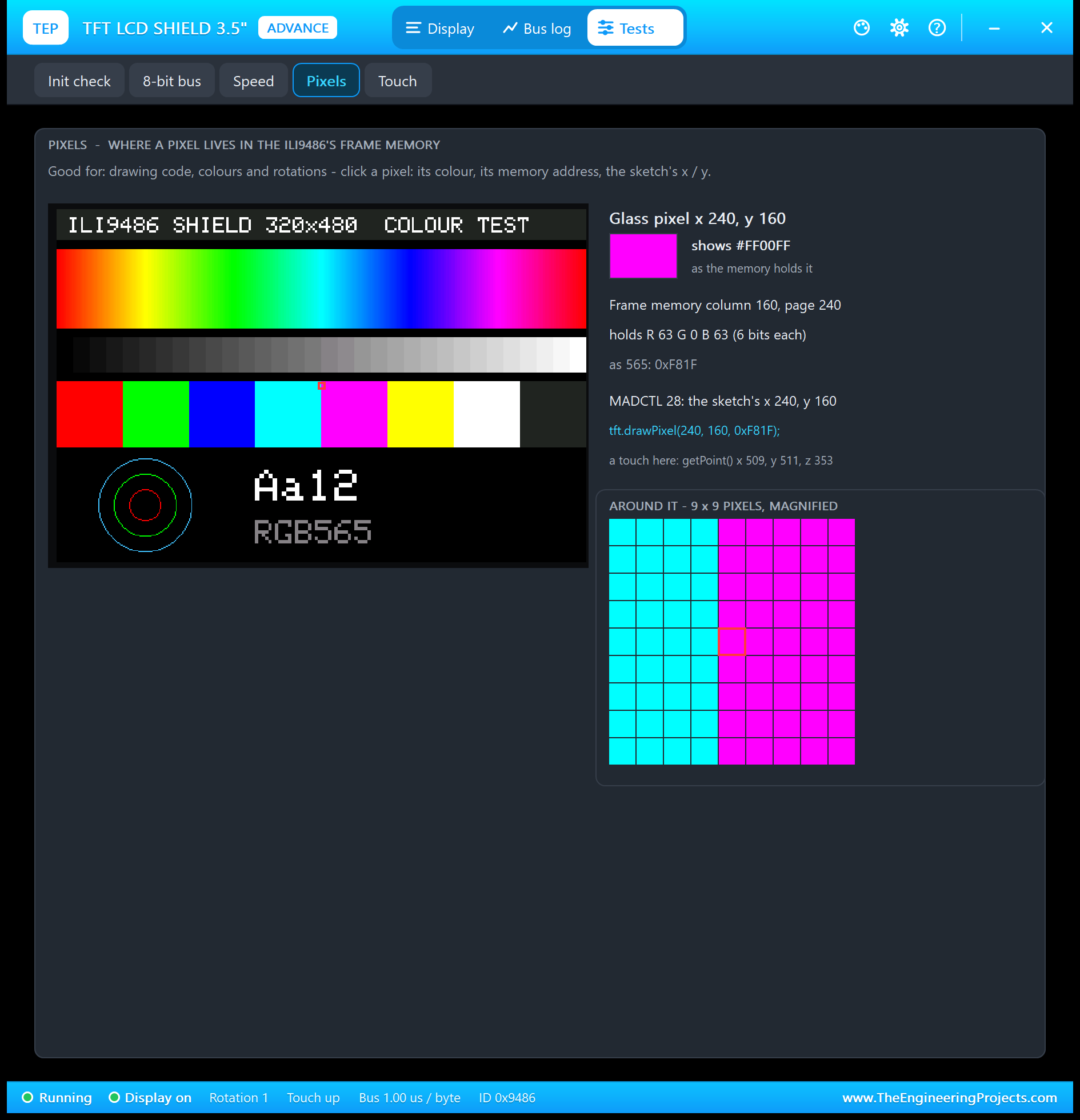
Click any of the 153,600 pixels to see its colour, its memory column and page, its 18 bits and RGB565 value, the sketch's coordinates in the current rotation and the raw touch values a press there would give.
5. Touch
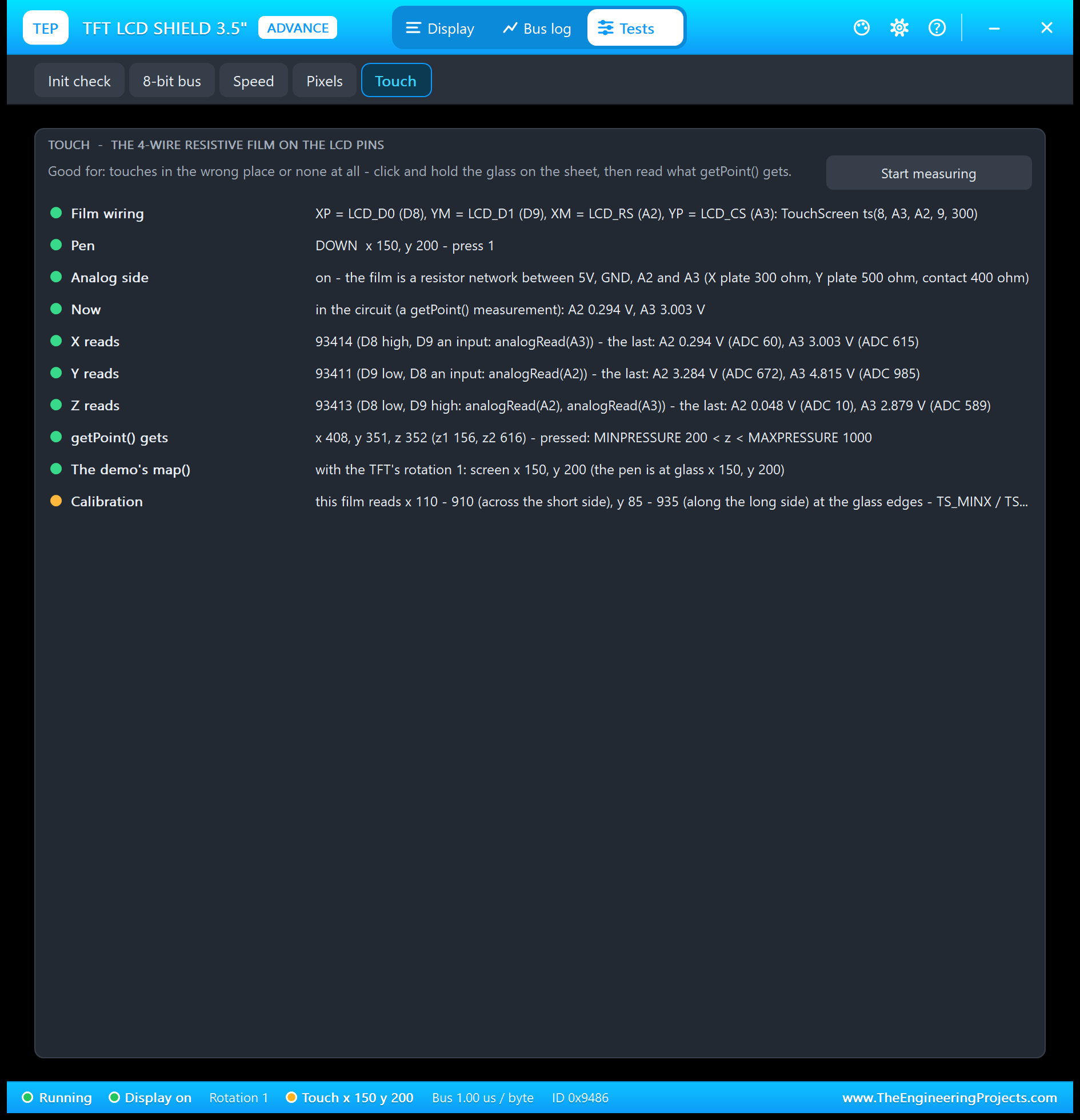
Good for touches in the wrong place or none at all: the film's pins, the pen, the voltages on A2 and A3 for the X, Y and Z readings with their ADC values, getPoint()'s x, y and z, and the screen point the demo's map() gives in the current rotation.
3.5" TFT LCD Shield with Arduino in Proteus
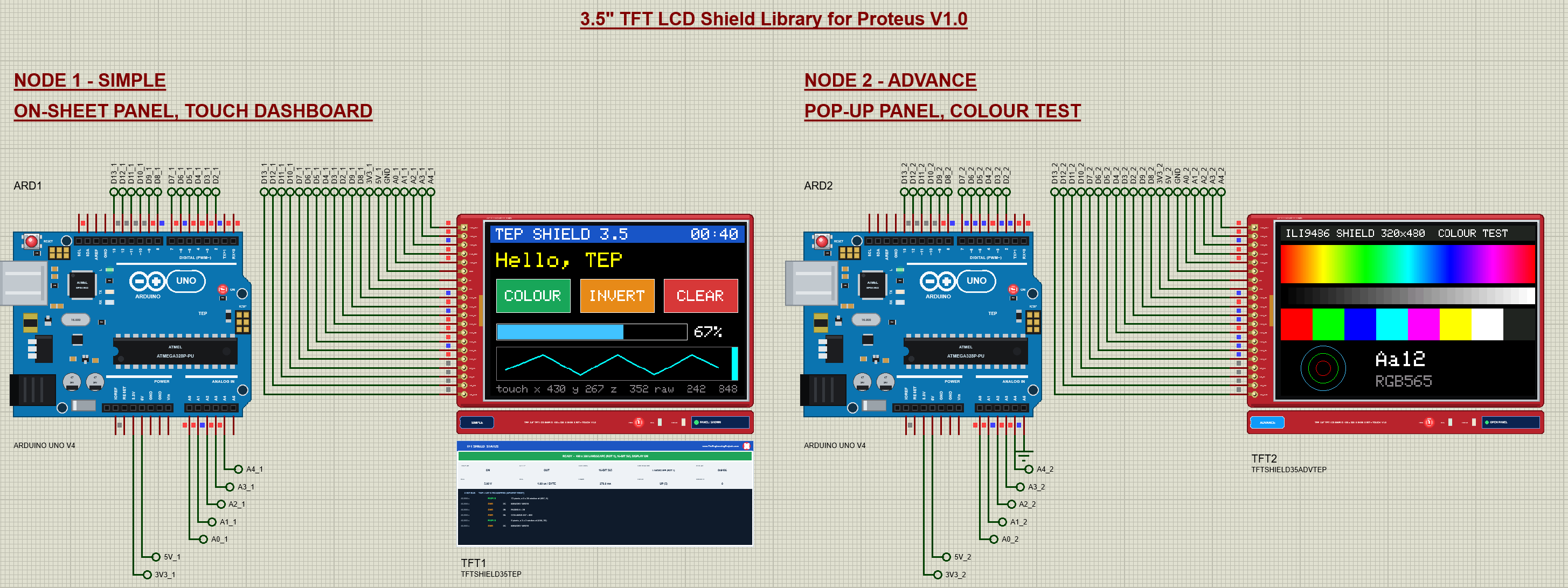
Open TFT-Shield-35-ArduinoUnoV4.pdsprj. Two Arduino UNO V4.0 boards from our Arduino UNO Library for Proteus V4.0 run the same sketch; ARD2's A5 is tied to GND, so it starts with the colour test. The monitors are built into the boards (see our Introduction to Arduino UNO for the pins).
Wiring
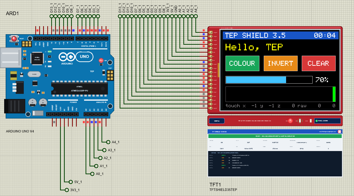
A real shield simply plugs on. In Proteus each shield pin meets the UNO pin it would plug into through a net label of the same name: LCD_RD A0, LCD_WR A1, LCD_RS A2, LCD_CS A3, LCD_RST A4, the data bits on D8, D9 and D2 - D7.
The Arduino Code
The sketch uses MCUFRIEND_kbv library 3.0.0, the Adafruit GFX library 1.12.6 and the Adafruit TouchScreen library 1.1.6:
#include <Adafruit_GFX.h>
#include <MCUFRIEND_kbv.h>
#include <TouchScreen.h>
The calibration of this film and the accepted pressure range:
#define TS_MINX 110
#define TS_MAXX 910
#define TS_MINY 85
#define TS_MAXY 935
#define MINPRESSURE 200
#define MAXPRESSURE 1000
The objects are the same as for any MCUFRIEND shield; the library finds the pins itself:
MCUFRIEND_kbv tft;                               // LCD_CS A3, LCD_RS A2, LCD_WR A1, LCD_RD A0, LCD_RST A4, LCD_D0-D7
TouchScreen ts = TouchScreen(XP, YP, XM, YM, 300);   // 300 ohm across the X plate
readID() decides which start-up begin() runs:
id = tft.readID(); // MCUFRIEND reads the controller's ID: 0x9486A big-screen button, 140 x 64 pixels, drawn white while it is pressed:
void button(int x, int y, const __FlashStringHelper* word, uint16_t colour, bool pressed) {
  tft.fillRect(x, y, 140, 64, pressed ? WHITE : colour);
  tft.drawRect(x, y, 140, 64, WHITE);
The slider redraws only its two parts, the filled bar and the rest:
void drawBar() {
  const int w = 356L * bar / 100;
  tft.fillRect(14, 186, w, 28, CYAN);
  tft.fillRect(14 + w, 186, 356 - w, 28, BLACK);
The touch reading, and the two lines that give the shared pins back to the TFT:
  TSPoint p = ts.getPoint();
  pinMode(XM, OUTPUT);                           // the film shares LCD_RS and LCD_CS: give them back to the TFT
  pinMode(YP, OUTPUT);
In rotation 1, the 480-pixel screen x comes from the raw y:
case 1: x = map(p.y, TS_MINY, TS_MAXY, 0, 480); y = map(p.x, TS_MAXX, TS_MINX, 0, 320); break;One more lesson from the colour test: on an UNO an int has 16 bits, and 479 x 255 does not fit, so the hue sweep computes with a long:
const int seg = h / 480, f = (h % 480) * 255L / 479; // 255L: 479 x 255 does not fit the UNO's 16-bit intSTATUS reads the ILI9486's registers back:
  hex(F("Power mode 0x0A: "), tft.readReg(0x0A));
  hex(F("MADCTL 0x0B: "), tft.readReg(0x0B));
And FILL times a full screen:
    const unsigned long t0 = millis();
    tft.fillScreen(BLUE);
    fillMs = millis() - t0;
To change the sketch, export a new HEX and load it into the UNO; see How to get the HEX file from Arduino. New to Arduino? Start with our Arduino Tutorial for Beginners.
Serial Monitor Commands
| Command | What it does |
|---|---|
| HELP / STATUS | The command list / the ID, rotation, screen, text, bar, registers read back, touches |
| TEXT <text> / BAR <0-100> | The big text / the slider |
| DASH / TEST / CAL / CLEAR | The dashboard / the colour test / the calibration / a black screen |
| FILL | A timed fillScreen of the whole 480 x 320 glass |
| ROTATE <0-3> | setRotation(): 1 upright, 3 upside down, 0 / 2 portrait |
| INVERT ON / OFF, SLEEP / WAKE | invertDisplay(); SLPIN / SLPOUT |
| TOUCH | The raw x / y / z now and the last screen point |
How to Run the Demo
- Press Run; move the monitor windows and TFT2's pop-up aside.
- Touch TFT1: COLOUR, INVERT, CLEAR, the slider, and draw in the paint strip with the button held down.
- Type STATUS, FILL, CAL, ROTATE 0 / ROTATE 1, SLEEP / WAKE in ARD1's monitor.
- Open TFT2's Tests and hold its glass while the Touch tool is open.
3.5" TFT LCD Shield Proteus Simulation Results
The Built-in Serial Monitor in Its Simple Interface
Each Arduino UNO V4.0 carries our TEP Serial Monitor Advance, wired inside the board to D0 / D1. The screenshots show its Simple interface (Ctrl+Shift+U; Esc for the full view). Read all about it in TEP Serial Monitor Advance for Proteus.
ARD1: The Touches
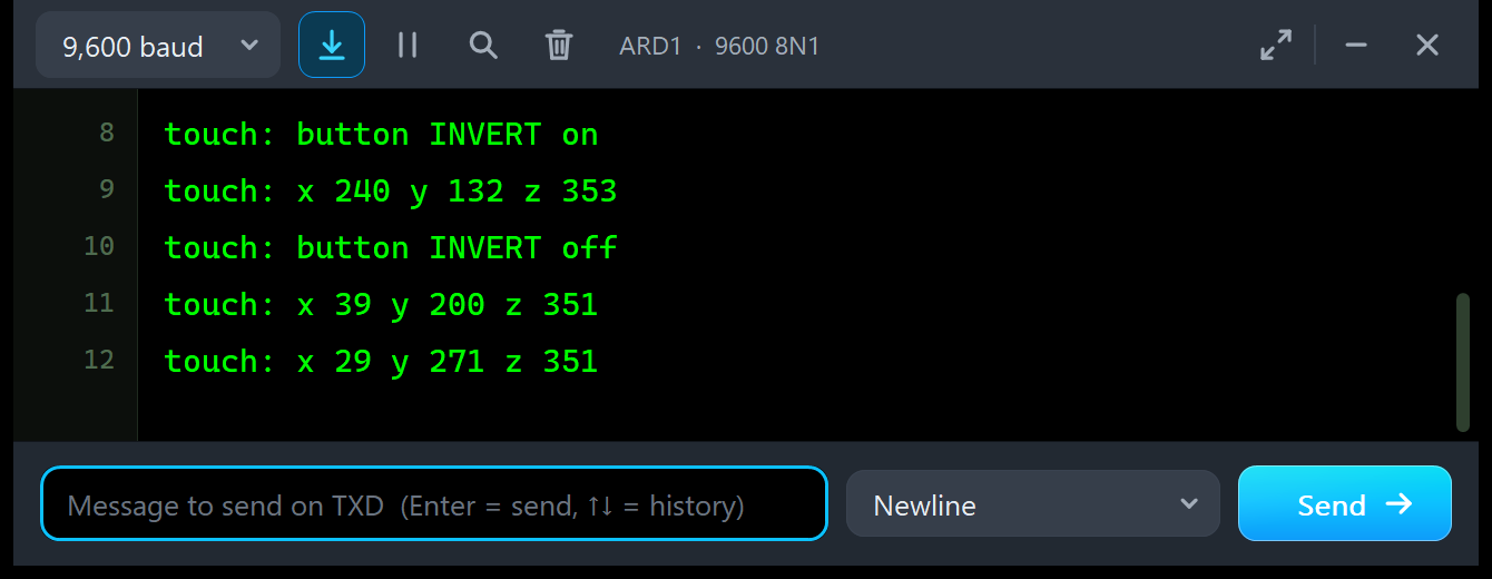
touch: button INVERT on
touch: x 240 y 132 z 353
touch: button INVERT off
touch: x 39 y 200 z 351
touch: x 29 y 271 z 351
ARD1: STATUS
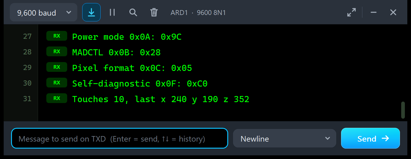
Power mode 0x0A: 0x9C
MADCTL 0x0B: 0x28
Pixel format 0x0C: 0x05
Self-diagnostic 0x0F: 0xC0
Touches 10, last x 240 y 190 z 352
ARD2: TOUCH and FILL
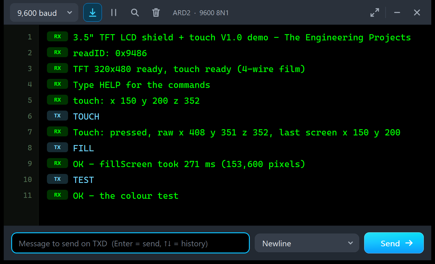
3.5" TFT LCD shield + touch V1.0 demo - The Engineering Projects
readID: 0x9486
TFT 320x480 ready, touch ready (4-wire film)
Type HELP for the commands
touch: x 150 y 200 z 352
TOUCH
Touch: pressed, raw x 408 y 351 z 352, last screen x 150 y 200
FILL
OK - fillScreen took 271 ms (153,600 pixels)
TEST
OK - the colour test
The sketch measures 271 ms with millis() and the Speed tool 270.8 ms on the bus: the same fillScreen from both sides.
Troubleshooting
- No power or a dark glass: check 5V and GND.
- WHITE SCREEN - NOTHING ON THE BUS YET: check LCD_CS, LCD_RS, LCD_WR and the eight data pins, and that the sketch calls
tft.begin(tft.readID()). - readID() prints a wrong ID: LCD_RD (A0) or a data pin is missing.
- STILL IN SLEEP / DISPLAY OFF / STILL ASLEEP: the start-up is incomplete or too fast;
begin()gets it right. - Colours inverted: the sketch sent INVON;
invertDisplay(false)sends INVOFF. - Touches in the wrong place: check the TS values with CAL and map the axes for your rotation.
- The picture stops after a touch: set A2 and A3 back to OUTPUT after
getPoint(). - The full screen is slow: that is the 3.5" glass on an UNO; redraw only what changes.
- No part or no monitor: TEPTFTSHIELD35.DLL or TEPARDUINO.DLL is missing from MODELS and the project folder; a closed monitor opens again with a click on the UNO's USB port.
Things to Know Before Using a Real 3.5" TFT LCD Shield
- Check the controller: run the demo and read the ID; ILI9486, ILI9488, ST7796 and others are sold on the same board, and MCUFRIEND_kbv supports most of them.
- Touch or no touch: make sure you buy the version with the touch film (MAR3501 on lcdwiki).
- Power: a 3.5" backlight draws noticeably more than a 2.4" one; power the UNO well (lcdwiki gives about 1.1 W for the board).
- Calibrate with CAL or MCUFRIEND's TouchScreen_Calibr_native example.
- Pins: only D0 / D1, D10 - D13 (the SD card) and A5 remain free on an UNO.
- Memory: the demo needs 31,392 bytes of flash and 753 bytes of RAM, near the UNO's limit; a Mega 2560 has room for bigger interfaces.
Limitations of the Simulation
- Not modelled: the ILI9486's 16-bit, RGB and SPI interfaces, the other controllers sold on the same board, the effect of gamma and power settings, response time, the current draw, the backlight (always on), more than one finger, the film's noise and drift, and the SD card.
- The LEDs, the strip and the panels are TEP additions.
- The model is our own, written from the ILI9486 datasheet; ILI9486 is an ILI Technology part. This library is not made or endorsed by ILI Technology, mcufriend, David Prentice, Adafruit or Labcenter.
- Licences: MCUFRIEND_kbv 3.0.0 (FreeBSD licence), Adafruit GFX 1.12.6 and Adafruit TouchScreen 1.1.6 (BSD licence), Adafruit BusIO 1.17.4 (MIT licence) and the Arduino AVR core 1.8.6 with LGPL-licensed code are in the HEX file; the README holds the licence texts.
- Tested in Proteus 8.5 in October 2026 (the demo as shipped on two Arduino UNO V4.0 boards with their built-in monitors: readID, the dashboard and the colour test, touches with the real mouse - a tap, a held button and a drag in the paint strip - and with presses fed to the model at exact times for these screenshots, CAL, the Serial commands with the register reads, INVERT, ROTATE, SLEEP / WAKE, FILL, the panel, the pop-up and the five tools; about 0.3 x real time with the pop-up and both monitors open). Proteus 7 is not supported.
Want a smaller screen? Our TFT LCD Shield Library for Proteus V1.0 has the 2.4" ILI9341 shield with the same pins and touch film, our TFT ILI9341 Library for Proteus V1.0 the ILI9341 as an SPI module, and our TFT ST7735 Library for Proteus V1.0 the little 1.8" colour TFT.
So, that was all about the 3.5" TFT LCD Shield Library for Proteus V1.0. I hope the ILI9486, the touch calibration and the art of redrawing only what changes are clear now, so your 480 x 320 interface works on the first real shield you plug in. If you use the 3.5" TFT LCD Shield Library for Proteus in a project, please share it in the comments or in our forum, and if you have any questions, ask in the comments and I will help you out. Till the next tutorial, take care and have fun!
Comments
0