


SHT31 Proteus Library


Hello friends, I hope you are doing well. In today's tutorial, I am going to share our SHT31 Proteus Library. This library lets us connect a temperature and humidity sensor model to an Arduino Uno, change both inputs during simulation and read the results on a Virtual Terminal. We can also examine the communication checks that help the program distinguish a valid measurement from a failed reading.
We will begin with the sensor's purpose, install the library, understand the circuit connections and run the supplied example. After that, we will go through the Arduino code and calculate how the digital readings become degrees Celsius and relative humidity. The download includes the working circuit, compiled HEX and editable source code, so you can start the simulation before setting up a compiler.
This tutorial uses our corrected V1.0.1 package with the TEP Arduino UNO V3.0 running at 16 MHz. The supplied project has documented run checks in Proteus 8.5 SP0. In the featured screenshot below, the controls have been adjusted to -10.0 C and 72.3 percent relative humidity, and the terminal shows the corresponding readings.
What Is the SHT31 Temperature and Humidity Sensor?
The SHT31 is a digital sensor for measuring temperature and relative humidity. It communicates with a controller over I2C, so our Arduino uses SDA and SCL to request and receive measurements. Sensirion's SHT3x-DIS datasheet is the primary reference for the physical device, command format and conversion equations.
Relative humidity describes the water-vapor partial pressure compared with the saturation vapor pressure at the same temperature, expressed as a percentage. A reading of 50 percent RH does not mean that half the air consists of water. The temperature reference matters because saturation vapor pressure changes with temperature.
In this tutorial, the Proteus component is named SHT31TEP. Its temperature and humidity sliders provide independent inputs to a digital model. We choose the environmental conditions and observe how the Arduino reads and processes them. The model does not measure your room or calculate how humidity changes automatically when you move the temperature slider.
This makes the example useful for learning communication, data conversion and application logic. For example, we can check whether a display handles negative temperatures correctly or whether a humidity indicator changes state at the intended threshold.
Download the SHT31 Library for Proteus
First of all, download the V1.0.1 archive below and extract the complete folder. Keep its directory structure intact for the initial run, especially the files stored alongside the simulation project.
Download SHT31 Proteus Library V1.0.1 and Arduino SimulationThe V1.0.1 release corrects the supplied project's sensor pin mapping. Open the project from this new folder rather than reusing an earlier test project with a newly copied DLL. The release notes identify the project correction; the sensor library, model DLL, sketch and compiled HEX remain unchanged.
| Folder | Contents and purpose |
|---|---|
| Proteus Library Files | TEPSHT31.LIB and the TEP Arduino UNO V3.0 library files. |
| Proteus Model Files | TEPSHT31.DLL, which provides the sensor's functional simulation. |
| Proteus Simulation | SHT31-ArduinoUnoV3.pdsprj, SHT31_Demo.hex and a local copy of the sensor DLL. |
| Arduino Code | The sketch, required library sources, AVR core archive and portable rebuild script. |
| Model Source and Documentation | Model implementation, supported features, recorded runtime checks and notices. |
There are two different kinds of library involved here. Proteus uses the LIB and DLL to place and simulate the component. Arduino uses a programming library to communicate with it. Installing one does not automatically install the other.
How to Install the SHT31 Proteus Library
Save your current work and close Proteus before copying the library files. Then follow these steps:
- Open the extracted Proteus Library Files folder.
- Copy
TEPSHT31.LIBinto the library directory configured for your Proteus installation. - Copy
ArduinoV3TEP.LIBandArduinoV3TEP.IDXif the TEP Arduino UNO V3.0 library is not installed already. - Copy
TEPSHT31.DLLfrom Proteus Model Files into the configured Proteus MODELS directory. - Restart Proteus and search for SHT31TEP in Pick Devices.
- Open the supplied V1.0.1 project for the first simulation.
Folder locations vary between Proteus installations, so use the paths your installation actually searches. The sensor is supplied as a native LIB without a separate sensor IDX file. The Arduino board's IDX belongs to that board library; do not rename it as an SHT31 index.
Leave the extra TEPSHT31.DLL beside the supplied project as well. SHT31_Demo.hex is the Arduino program, so it belongs in the Uno's Program File property. The sensor uses its DLL model rather than a sensor HEX.
The recorded compatibility checks cover the supplied wired project in Proteus 8.5 SP0. They do not establish compatibility with Proteus 7 or every custom schematic. If you need the board installation explained separately, see our Arduino Library for Proteus V3.0 tutorial.
SHT31 Pinout and Arduino Uno Connections
The model has six labeled pins along its lower edge: VIN, GND, SCL, SDA, ADDR and ALERT. Connect wires to their exposed endpoints below the board, using the labels to identify each signal.
| Sensor pin | Connection | Purpose |
|---|---|---|
| VIN | Positive supply rail | Powers the digital model. |
| GND | Common ground | Provides a shared electrical reference. |
| SCL | Arduino Uno A5 | Carries the I2C clock. |
| SDA | Arduino Uno A4 | Carries I2C data. |
| ADDR | Ground | Selects the seven-bit address 0x44 used by the sketch. |
| ALERT | Unconnected | Not used by this example; programmable alert thresholds are outside this model's implementation. |
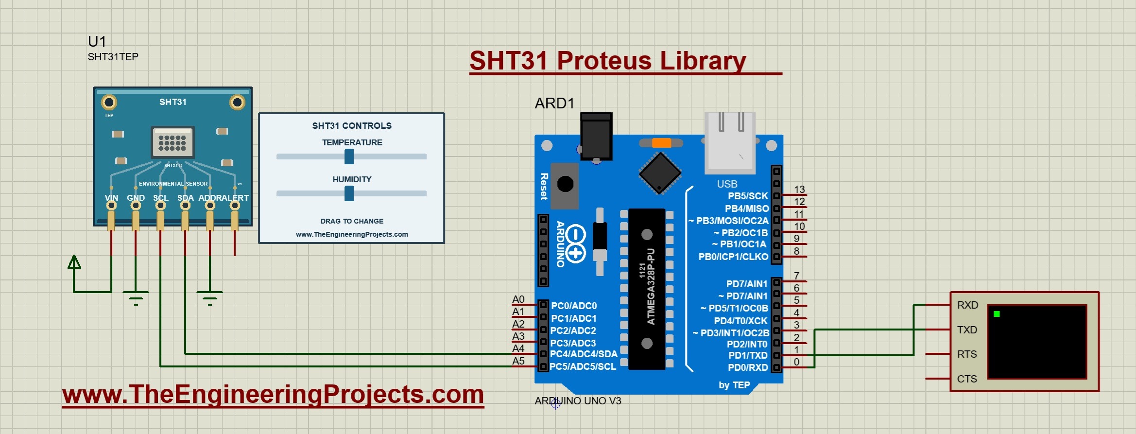
Connect Arduino D1/TX to the Virtual Terminal's RXD pin. Select 9600 baud, eight data bits, no parity and one stop bit. The return connection from terminal TXD to D0/RX appears in the circuit, but the sketch does not require incoming serial commands.
The Uno must run at 16 MHz for the supplied firmware. A mismatched clock can affect communication and serial output, even when the wires look correct.
The supplied digital example uses the AVR Wire implementation's internal pull-ups. When moving to hardware, check the actual breakout's supply requirements, logic levels and pull-ups. The schematic's positive rail does not document the circuitry fitted to every physical SHT31 module.
Run the Temperature and Humidity Simulation
- Open
Proteus Simulation/SHT31-ArduinoUnoV3.pdsprjfrom the extracted V1.0.1 folder. - Keep SHT31_Demo.hex and TEPSHT31.DLL alongside the project.
- Confirm the Uno's Program File and 16 MHz clock.
- Check ADDR is grounded and the terminal is set to 9600 baud.
- Press Run and open the Virtual Terminal window.
The documented starting conditions are 25 C and 50 percent RH. You should see the startup message followed by repeated temperature and humidity lines. Allow several readings to appear before changing a control so that the initial condition is easy to recognize.
Next, drag the temperature slider left. In the supplied running screenshot, the temperature changes from 25.0 C to -10.0 C while humidity initially remains at 50.0 percent. Moving the humidity slider then changes the second reading to 72.3 percent.
This sequence is a useful first experiment because it changes one variable at a time. You can see which output responds, check the negative sign and confirm that the other channel is still being read.
The V1.0.1 runtime notes also record a separate check at 60 C and 78.4 percent RH without CRC errors. These are documented release checks, while the attached screenshot shows the different conditions used for this article.
Understand the Model Controls
| Property | Range | Default |
|---|---|---|
| TEMPERATURE | -40 to 125 C | 25 C |
| HUMIDITY | 0 to 100 percent RH | 50 percent RH |
Move the blue handles or click their tracks during a run. For an exact initial value, stop the simulation and edit TEMPERATURE or HUMIDITY in the component properties. Restarting restores those configured values rather than preserving the last dragged positions.
The controls are independent. Choosing an extreme temperature does not automatically alter relative humidity, introduce condensation or change the response speed. These are functional inputs for testing software, not a complete model of an enclosure's environmental behavior.
Do not interpret slider resolution or the number of displayed decimal places as a physical accuracy specification. For hardware, use the manufacturer's accuracy curves and conditions. In this example, our immediate goal is to confirm the values, units and error handling passed through the program.
Arduino Code for the SHT31 Proteus Simulation
The following code is the exact sketch included in the archive. It uses the bundled Adafruit SHT31 library version 2.2.2. Keeping that version for the first build makes the source and supplied demonstration easier to compare.
#include <Wire.h>
#include <Adafruit_SHT31.h>
Adafruit_SHT31 sensor;
bool ready=false;
void setup() {
  Serial.begin(9600); Wire.begin(); Wire.setWireTimeout(25000,true);
  ready=sensor.begin(0x44);
  Serial.println(ready ? F("TEP SHT31 - drag the temperature and humidity sliders.") : F("SHT31 not found. Check power, SDA, SCL and ADDR."));
}
void loop() {
  if(ready) {
    float temperature,humidity;
    if(sensor.readBoth(&temperature,&humidity)) {
      Serial.print(F("Temperature: ")); Serial.print(temperature,1);
      Serial.print(F(" C | Humidity: ")); Serial.print(humidity,1); Serial.println(F(" %"));
    } else Serial.println(F("Measurement or CRC error."));
  }
  delay(500);
}
Start Serial and I2C Communication
Serial.begin sets the output speed to 9600 baud. Wire.begin initializes I2C, and Wire.setWireTimeout limits a low-level bus wait to 25,000 microseconds, or 25 ms, with reset enabled on timeout.
The call sensor.begin uses address 0x44, matching the grounded ADDR pin. Its result is stored in ready. If initialization fails, the sketch prints the wiring checks instead of proceeding with ordinary measurements. After correcting the circuit, restart the simulation so setup runs again.
Read Both Measurements Together
The function sensor.readBoth(&temperature, &humidity) obtains the temperature and humidity from one measurement operation. In the bundled driver, calling readTemperature and readHumidity separately would trigger separate acquisitions. Reading both together keeps the pair associated with the same acquisition and avoids that extra work.
The function returns a success flag. The sketch prints numeric results only when it succeeds; otherwise, it prints Measurement or CRC error. A failed measurement should not become a zero-temperature or zero-humidity reading in an application, because both zero values can be legitimate inputs.
The second argument of each Serial.print call is 1, which requests one decimal place. This controls formatting. It does not change the model input or improve the measurement accuracy.
Allow Time for a Measurement
The bundled driver sends the high-repeatability command 0x2400 without clock stretching and waits 20 ms before reading. The model's corresponding conversion-ready delay is 15.5 ms, so the normal read occurs after that wait has elapsed.
The loop then waits another 500 ms. Including acquisition and printing, the terminal updates slightly less often than twice per second. Reducing the loop delay alone does not remove the conversion time or serial transmission time.
The model also implements other repeatability delays and periodic measurement modes, but this sketch requests a fresh single-shot measurement each time. It does not use periodic acquisition or the ALERT output.
Convert Raw SHT31 Data into Temperature and Humidity
The device returns each measurement as two data bytes with an additional CRC byte. Combine the high and low bytes as raw value = high byte × 256 + low byte. These are unsigned 16-bit counts, including when the final temperature is negative.
The ideal conversion equations are temperature in C = -45 + 175 × raw temperature / 65535 and relative humidity in percent = 100 × raw humidity / 65535. The temperature offset is what allows an unsigned count to represent temperatures below zero.
Worked Temperature Examples
For a raw temperature of 26214, the fraction 26214 / 65535 equals 0.4. The equation gives -45 + 175 × 0.4 = 25 C. That count is 0x6666, so both temperature data bytes are 0x66.
For a raw temperature of 13107, the fraction is 0.2. The result becomes -45 + 175 × 0.2 = -10 C. There is no need to reinterpret that raw value as a signed negative integer. Doing so would apply the wrong representation.
The bundled Adafruit driver uses an efficient integer approximation with a denominator of 65536 and hundredth-unit truncation. Its internal converted values can therefore differ slightly from the ideal equations. The sketch then prints one decimal place, which explains why a displayed result can agree with a slider even though intermediate calculations differ by a small fraction of a degree.
Worked Humidity and Unit Examples
A raw humidity count of 32768 represents approximately 50.0008 percent using the ideal equation. At the example's one-decimal display precision, that is 50.0 percent. Keep enough precision internally if your later calculations need it, and round when formatting the output.
For a Fahrenheit display, use F = 1.8 × C + 32. The screenshot's -10 C becomes 14 F. Convert after obtaining a valid Celsius measurement, and change the printed unit so readers do not mistake the new number for Celsius.
Why the CRC Check Matters
A measurement response contains six bytes: temperature high byte, temperature low byte, temperature CRC, humidity high byte, humidity low byte and humidity CRC. Each CRC covers its own two data bytes, so the two channels are checked separately.
The CRC-8 calculation uses polynomial 0x31 and initial value 0xFF. The bundled driver verifies both checks before returning successful paired readings. You do not need to add a second manual CRC routine around readBoth for this example.
CRC helps detect a damaged data frame. It does not prove that a physical sensor is calibrated, correctly positioned or accurately measuring its surroundings. Similarly, a valid CRC in this simulation confirms the modeled data exchange, not a real environmental experiment.
If a read occurs before the model's conversion is ready, it is not accepted as a completed measurement. The supplied driver includes the required wait. When writing your own driver, preserve the measurement delay and read the full six-byte frame before accepting either value.
Address Selection and a Humidity Threshold Exercise
Grounding ADDR selects 0x44. Taking it high selects 0x45, and the firmware address must change to match. A circuit at 0x45 with the original 0x44 HEX will fail initialization; changing a source file without compiling a new HEX does not update the running firmware.
These two addresses allow an experiment with two SHT31 models on the same I2C bus, provided each has a different ADDR state and its own driver object. First confirm the supplied single-sensor circuit before adding another device.
For a simple application exercise, set a high-humidity indication above 60 percent RH and clear it below 55 percent RH. Between those limits, retain the previous state. The separation is five percentage points and introduces hysteresis around the switching decision.
Apply the rule only after readBoth succeeds. If a measurement fails, show an unavailable state or explicitly identify the last valid reading as old. Do not silently reuse it as a fresh measurement.
Compile Your Changes and Check the Result
- Open
Arduino Code/SHT31_Demo/SHT31_Demo.inoin Arduino IDE. - Select Arduino Uno and the documented Arduino AVR Boards 1.8.6 core.
- Install the supplied libraries from Arduino Code/libraries, including their dependencies.
- Compile and export the application HEX after making changes.
- Choose the new HEX in the Uno's Program File property and restart the simulation.
The portable rebuild script offers another route; its README explains the required compiler paths. Keep the original project and HEX available so you can compare a modified build with the supplied example.
A useful test sequence is 25 C and 50 percent RH, then -10 C at the same humidity, then 72.3 percent RH at the same temperature. Finally, restart and check that the configured initial conditions return. This covers both inputs, negative-temperature formatting and restart behavior.
Common Problems and Their Solutions
| Problem | What to check |
|---|---|
| SHT31TEP is missing from Pick Devices. | Check TEPSHT31.LIB in the active library directory and restart Proteus. |
| An older project reports missing sensor pins. | Open the corrected project from the complete V1.0.1 archive. |
| The simulation model will not load. | Check TEPSHT31.DLL in MODELS and beside the project. |
| SHT31 not found. | Check supply, ground, SDA/A4, SCL/A5 and ADDR matching the firmware address. |
| Measurement or CRC error. | Check communication, the conversion wait and use of the supplied driver and model versions. |
| Terminal output is missing or unreadable. | Check the HEX path, 16 MHz clock, D1/TX to RXD and 9600 baud. |
| Edited code has no visible effect. | Compile again, select the new HEX and restart the simulation. |
Practical Review and FAQs
The library supports useful exercises in paired readings, CRC validation, address selection and temperature or humidity display logic. It provides deterministic inputs rather than modeling sensor noise, calibration drift or an enclosure's thermal and moisture response. Heater enable and status behavior are represented, but heater-driven temperature changes are not simulated.
Does the SHT31 Measure Pressure?
No. This example provides temperature and relative humidity. If your project needs pressure as well, choose an appropriate additional sensor or a combined environmental sensor.
Why Is ALERT Left Unconnected?
The sketch reads measurements through I2C, and this model does not implement programmable alert thresholds. An indicator can instead be controlled by Arduino code after validating the readings.
Can I Change the Inputs While It Is Running?
Yes. Drag the two controls during simulation. Edit the component properties while stopped when you want specific values restored at startup.
Why Does Changing Temperature Leave Humidity Unchanged?
The model exposes independent inputs. It does not calculate a physical humidity change from a temperature change. Set both conditions explicitly for your experiment.
Do I Need to Compile the Code Before the First Run?
No. The included HEX runs the supplied demonstration. Compile when you change the sketch, its address or the output behavior.
That completes our SHT31 Proteus Library tutorial. Start with the supplied circuit, change one input at a time and keep the success check around your measurements. Once you understand the readings, you can build your own environmental display or threshold exercise. Share your questions and results in the comments below.
Comments
0