


L293D Motor Shield Library for Proteus Simulation


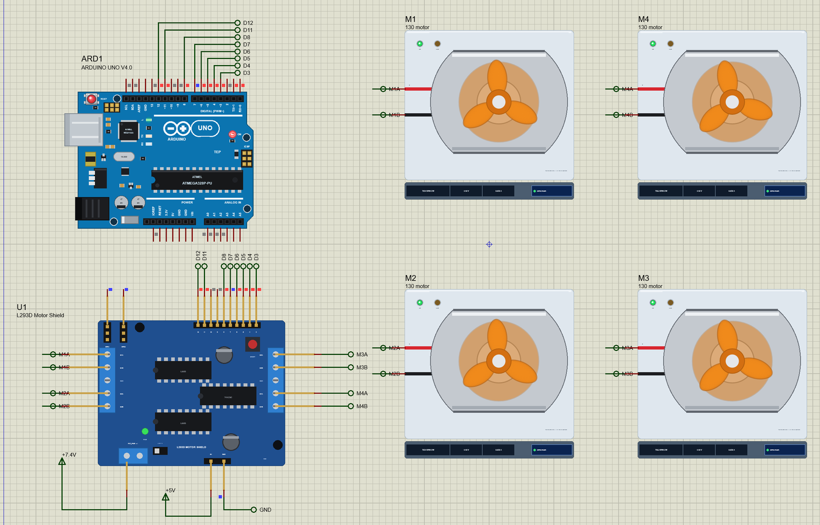
Hello friends, I hope you all are doing great. Today, I am going to share the new L293D Motor Shield Library for Proteus Simulation, the 48th library of our motor series. If you have searched for a Proteus simulation of the L293D motor driver shield, the board that turns an Arduino UNO into the brain of a four-wheel robot car, this library brings the whole shield into Proteus: its two L293D chips, the 74HC595 shift register that holds the motor directions, the four speed pins and the two servo headers.
L293D Motor Shield Library for Proteus Simulation
Latest version: V1.0 (November 2026, this tutorial)
Helping Tools
- Serial Monitor Advance: a serial terminal window for the UART of your board
- Serial Monitor Expert: the serial monitor with extra debugging tools
- LCD Library for Proteus V3.0: 16x2, 20x4 and I2C LCDs to show your readings
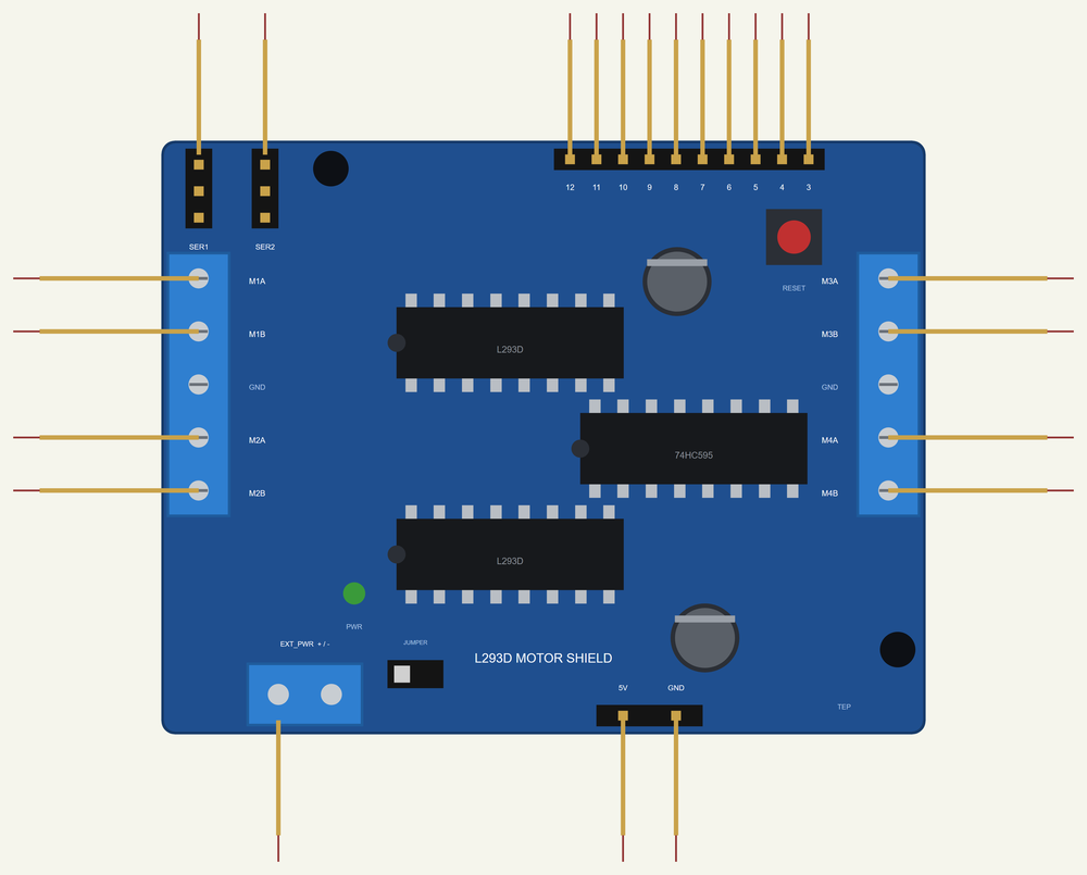
The shield is drawn at its true size, the 68.6 x 53.3 mm board of the UNO's own outline, with its chips, its blue terminal blocks for M1 to M4 and the external power, the servo headers, the PWR jumper, the LED and the reset key. The simulation model follows the shield bit by bit: the eight direction bits travel through the 74HC595 exactly as on the real board, the L293D enables take the speeds, and the four motor outputs carry the real drops of the L293D's Darlington transistors. In the demo an Arduino drives four of our 130 DC motors as a robot car: forward, a turn, a spin and backward.
NOTICE: Our team has put a lot of effort into these small parts: the bodies, the animation and the pop-ups are all our own design, and you get them free. Your feedback is the fuel that keeps us going, so please tell us what you think in the comments below or in the Motor Driver board of our forum. And if our free libraries help you, you can buy us a coffee. So, let's get started with the L293D Motor Shield Library for Proteus Simulation:
What is the L293D Motor Shield?
The L293D motor shield is one of the oldest and most widely sold Arduino shields. It plugs straight onto an UNO and drives four DC motors, or two stepper motors, plus two hobby servos, which is exactly what a four-wheel robot car needs. It is an open design: the original board was released with its schematics, and countless copies of it are sold under many names, all with the same layout and the same pin use, so one Arduino sketch works on all of them.
The motors are driven by two L293D chips. Each L293D holds four half-H drivers, so two of them pair up into one full H-bridge for a motor: the shield has four such bridges, M1 to M4. The trick that makes four motors fit on an UNO is the 74HC595 shift register. A motor needs two direction signals and one speed signal; four motors would need twelve pins. The shield sends all eight direction bits through the shift register on just four pins, and only the four speeds use PWM pins of their own.
| The L293D motor shield | |
|---|---|
| Motor drivers | two L293D: four H-bridges (M1 - M4), 600 mA a channel, 1.2 A peak |
| Motor supply | EXT_PWR 4.5 - 25 V (or the UNO's supply through the PWR jumper) |
| Directions | a 74HC595: data D8, clock D4, latch D12, output enable D7 |
| Speeds | the L293D enables: M1 D11, M2 D3, M3 D6, M4 D5 (PWM) |
| Servos | two 3-pin headers: SER1 on D9, SER2 on D10, 5 V |
| Free pins | D2, D13 and the analog pins A0 - A5 |
| Board | 68.6 x 53.3 mm, the outline of the UNO |
How the 74HC595 Sets the Directions
A 74HC595 is a serial-in, parallel-out shift register. The Arduino puts one bit on the data pin, D8, and pulses the clock pin, D4: on each rising edge the register shifts its eight bits along by one and takes the new bit in. After eight clock pulses all eight bits are inside, but the outputs have not changed yet; a pulse on the latch pin, D12, copies them to the outputs in one step, so the motors never see half a byte. The output enable, D7, must be low for the outputs to work.
Each motor owns two of the eight bits, one for each side of its bridge: M1 uses bits 2 and 3, M2 bits 1 and 4, M3 bits 5 and 7 and M4 bits 0 and 6. Bit A set and bit B clear turns the motor forward, the other way backward, and both clear releases it. The order looks random because it follows the wiring of the board, not a pattern; the shield's usual Arduino library uses exactly this map, and so does our demo sketch. For example, all four motors forward is bits 0, 1, 2 and 5: the byte 0x27.
| Motor | Bit A (forward) | Bit B (backward) | Speed pin |
|---|---|---|---|
| M1 | 2 | 3 | D11 |
| M2 | 1 | 4 | D3 |
| M3 | 5 | 7 | D6 |
| M4 | 0 | 6 | D5 |
The L293D and its Voltage Drop
The L293D is a bipolar driver: its output transistors are Darlington pairs, and a Darlington never switches fully on. The datasheet gives a typical drop of about 1.4 V on the high side and 1.2 V on the low side at its rated current, so a motor on this shield gets roughly 2.5 V less than the supply. On a 7.4 V battery a motor sees a little under 5 V. That is the price of this simple, rugged chip, and the reason modern boards use MOSFET drivers such as the DRV8833 or the TB6612FNG.
The enable pin of each channel pair is the speed: high, the outputs follow their direction inputs; low, both outputs open and the motor coasts. A PWM on the enable gives the speed. The L293D has clamp diodes built in to catch the motor's current when the outputs open, but it has no current limit, only a thermal shutdown, so its ratings, 600 mA per channel and 1.2 A for short peaks, are up to you.
Features of the L293D Motor Shield Library for Proteus Simulation
- The shield at true scale: the 68.6 x 53.3 mm board with two L293D, the 74HC595, the M1 / M2 and M3 / M4 terminal blocks, EXT_PWR, the two servo headers, the PWR jumper, the reset key and the LED, which lights when the motor supply is on.
- The 74HC595 bit by bit: the data, clock, latch and enable pins work as on the real chip, so any sketch for the real shield works unchanged.
- Four motor channels: each enable's PWM measured period by period, the Darlington drops, the clamp diodes, solved with the motors.
- The ratings and the heat: currents over 600 mA for half a second or over 1.2 A are logged; each chip's die temperature from its losses.
- The servo headers: D9 and D10 passed through to SER1 and SER2, the pulse width shown in the pop-up.
- A pop-up: the 74HC595's eight bits, the four motors with their direction, speed, voltage and current, the UNO pins in use, eight live values, graphs, an event log and a check page.
- A complete package: about 1.2 MB with the library, our Arduino UNO V4.0 and the demo, without the source code of the model.
The L293D Shield in Proteus
The device is L293DSHIELDTEP in TEPL293DSHIELD.LIB, under Electromechanical > Motor Drivers, with the prefix U and the mixed model TEPL293DSHIELD.DLL. Search L293DSHIELD in Pick Devices. Proteus cannot stack a shield on a board, so the shield is a part of its own: the UNO pins it uses, D3 to D12, stand along its top edge with the two servo signals SER1 and SER2; M1A, M1B, M2A and M2B are on the left, M3A to M4B on the right, and EXT+, 5V and GND along the bottom. Wire its pins to the UNO's with labels of the same names. It has no properties.
Download L293D Motor Shield Library for Proteus Simulation
Click the button below to download L293D-Motor-Shield-Library-for-Proteus-v1.0.zip (about 1.2 MB, without the source code of the models):
L293D Motor Shield Library for Proteus V1.0- README.txt: installation, the demo, the wiring, troubleshooting and the limits of the simulation.
- Proteus Library Files:
TEPL293DSHIELD.LIBandArduinoV4TEP.LIB. - Proteus Model Files:
TEPL293DSHIELD.DLLandTEPARDUINO.DLL. - Arduino Code: the demo sketch.
- Proteus Simulation: the demo project, its HEX file and copies of the DLLs.
No Proteus yet? Read How to Download and Install Proteus 7 and 8. New to libraries? Follow How to Install a New Library in Proteus.
How to Install L293D Motor Shield Library for Proteus Simulation
- Close Proteus and extract the whole zip file, for example to your Desktop.
- Copy the files from Proteus Library Files into the LIBRARY folder of Proteus.
- Copy the files from Proteus Model Files into the MODELS folder.
- Delete
TEPL293DSHIELD.IDXfrom the LIBRARY folder if it is there. - The demo's motors are our separate 130 DC Motor Library for Proteus: install its LIB and DLL too.
- Start Proteus, press P and search for L293DSHIELD.
Proteus Simulation of the L293D Shield with Arduino
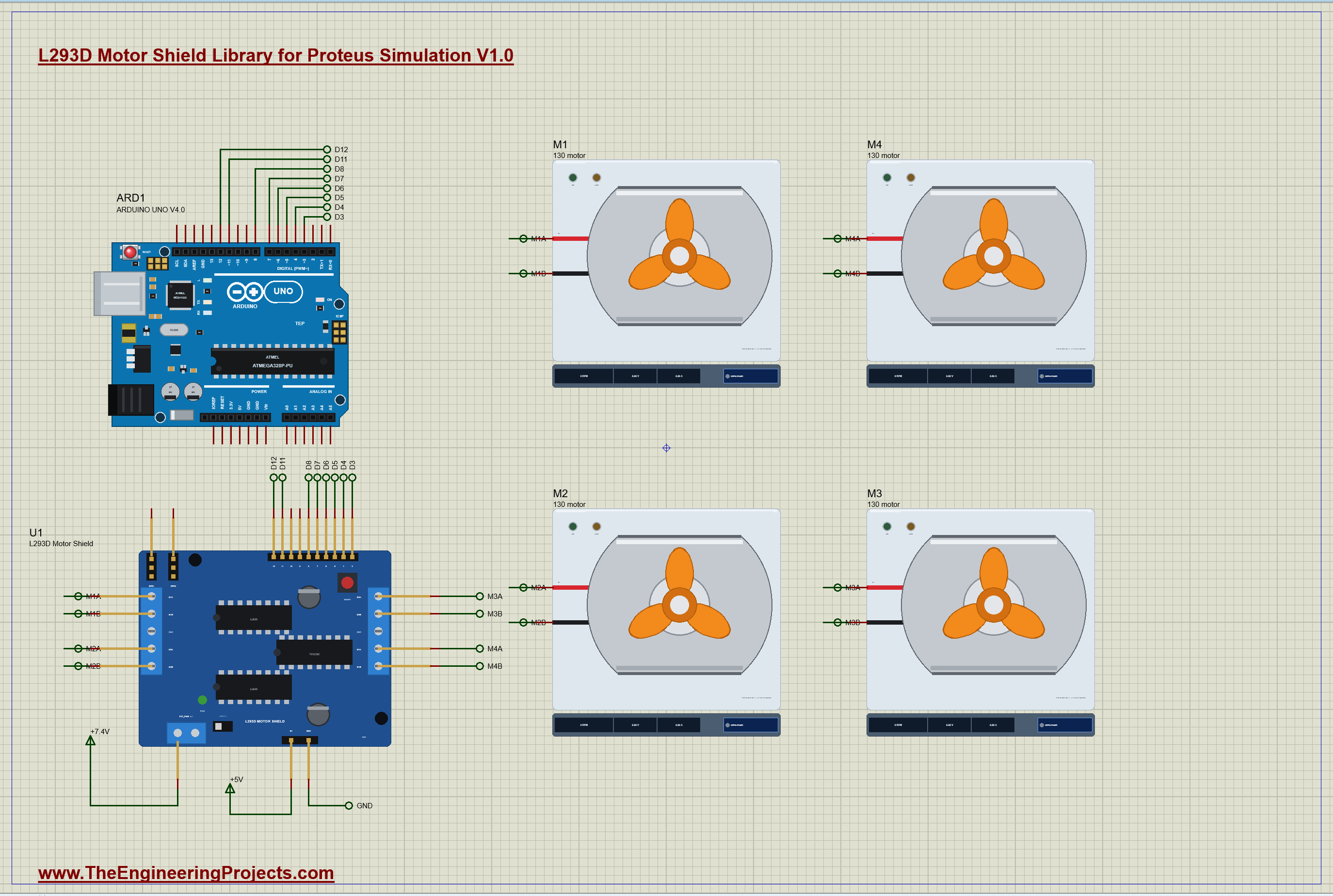
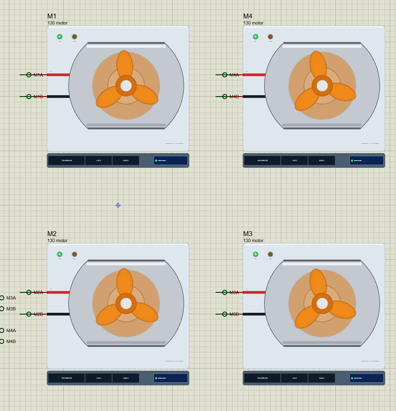
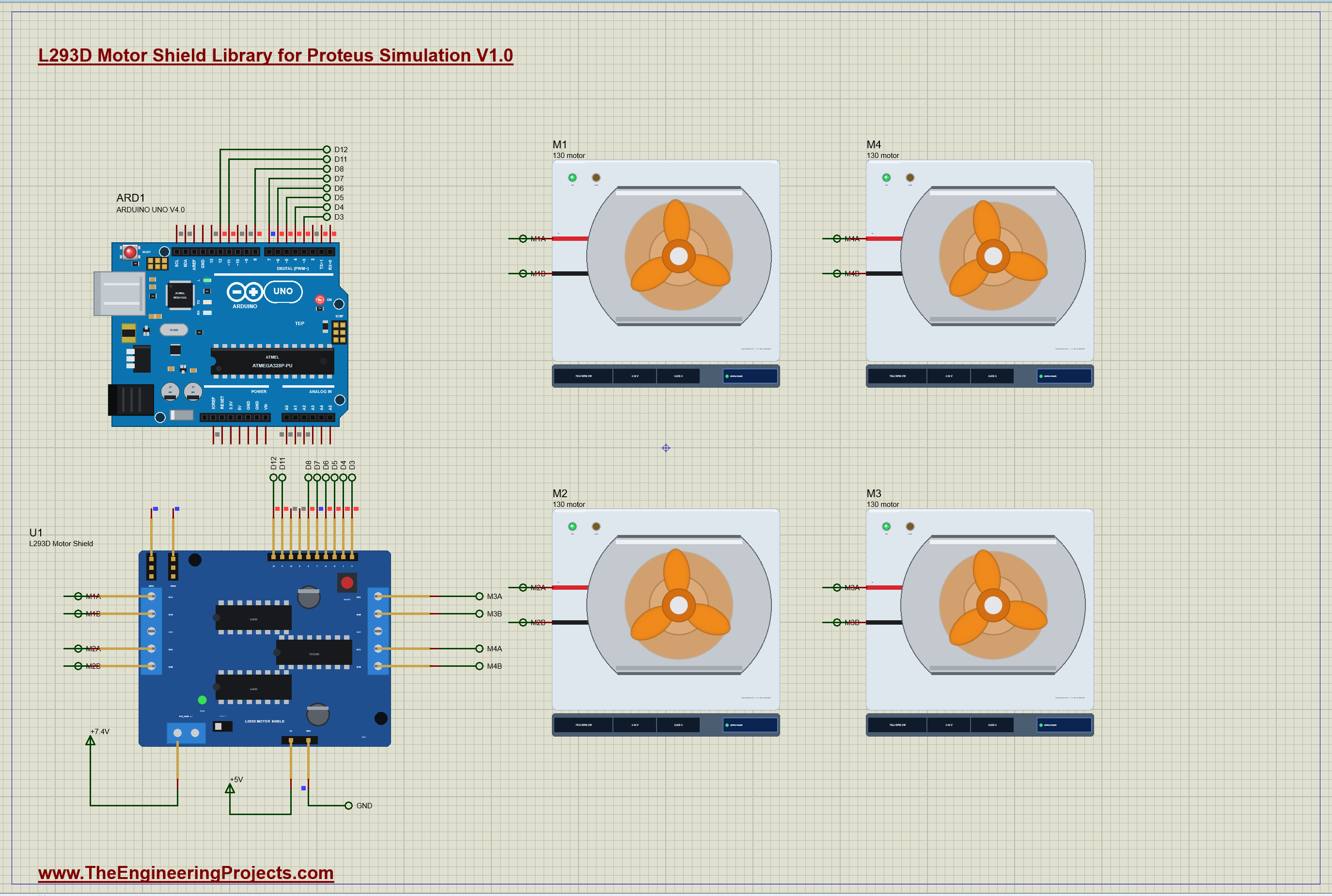
The demo has our Arduino UNO Library for Proteus V4.0 with its built-in monitor, the same window as our TEP Serial Monitor Advance for Proteus. U1 is the shield beside it, its pins D3 to D8, D11 and D12 joined to the UNO's by labels, EXT+ on a 7.4 V terminal, two Li-ion cells, and its logic on 5 V. The motors are four of our 130 DC motors from our separate 130 DC Motor library (TEP130MOTOR.LIB and TEP130MOTOR.DLL), so install it first: M1 and M2 are the left wheels, M3 and M4 the right wheels of the robot car. Open L293DSHIELD-MOTOR130-ArduinoUnoV4.pdsprj.
The Sketch
The sketch does not need a library: it writes the shield's eight bits itself, the way the usual library does. latchTx() shifts the byte out MSB first, one clock pulse a bit, and then pulses the latch:
void latchTx() {                                                         // the eight bits into the 74HC595, MSB first, then latched
  digitalWrite(LATCH, LOW);
  for (int8_t i = 7; i >= 0; --i) { digitalWrite(CLK, LOW); digitalWrite(DATA, (latchState >> i) & 1); digitalWrite(CLK, HIGH); }
  digitalWrite(LATCH, HIGH);
}
A motor's speed from -255 to 255 sets its two bits and its enable's PWM:
  latchState &= ~(_BV(BIT_A[m]) | _BV(BIT_B[m]));
  if (speed > 0) latchState |= _BV(BIT_A[m]); else if (speed < 0) latchState |= _BV(BIT_B[m]);
A robot car is just the left pair and the right pair:
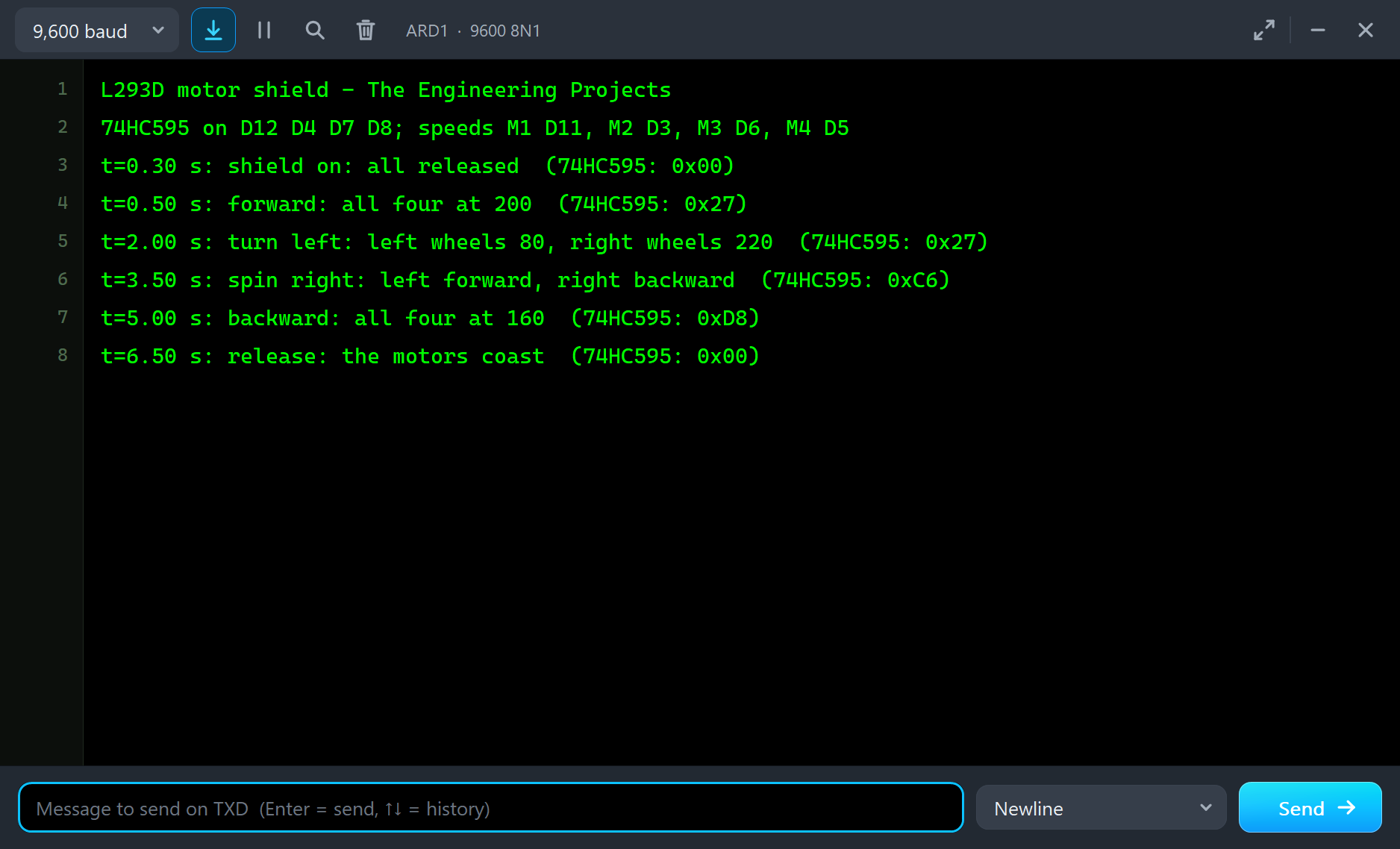
void car(int left, int right) { motor(0, left); motor(1, left); motor(2, right); motor(3, right); }The program switches the shield on at 0.3 s (the register cleared, D7 low), drives forward at 200 at 0.5 s, turns left at 2 s (left wheels 80, right wheels 220), spins right at 3.5 s, drives backward at 160 at 5 s and releases all four at 6.5 s. Each step prints the 74HC595's byte on the monitor. Afterwards you can type m 1 150 to run one motor.
L293D Shield Simulation Results
Open the project and press Run. The program runs about 7 simulated seconds; with all the pop-ups open and the pictures being taken it took about two and a half minutes on our PC. Click the shield for its pop-up and each motor for its own. Every number below comes from one simulation run, the demo exactly as it ships.
Forward: the Byte 0x27
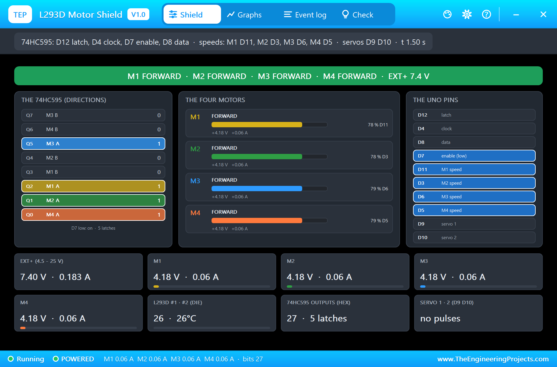
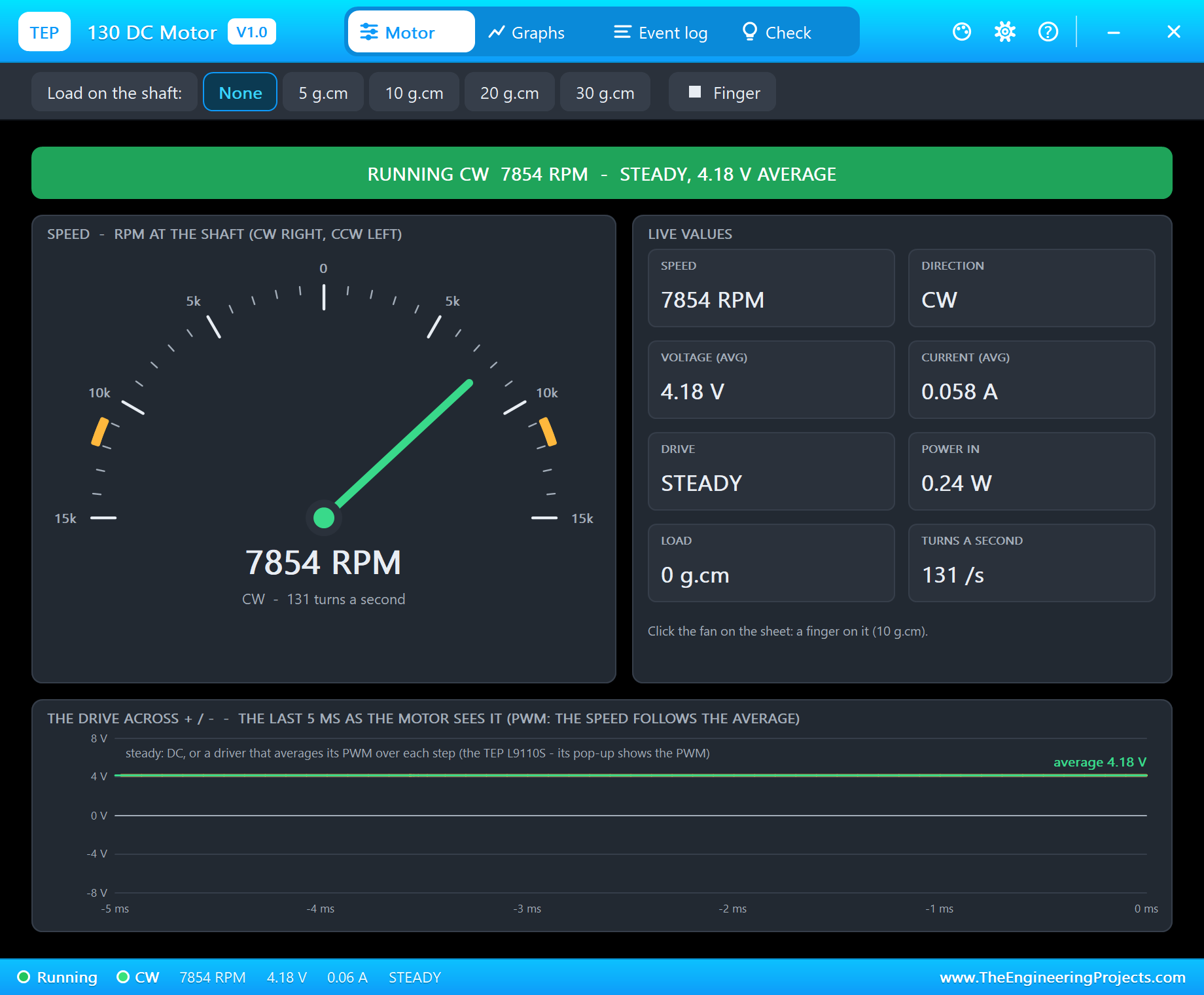
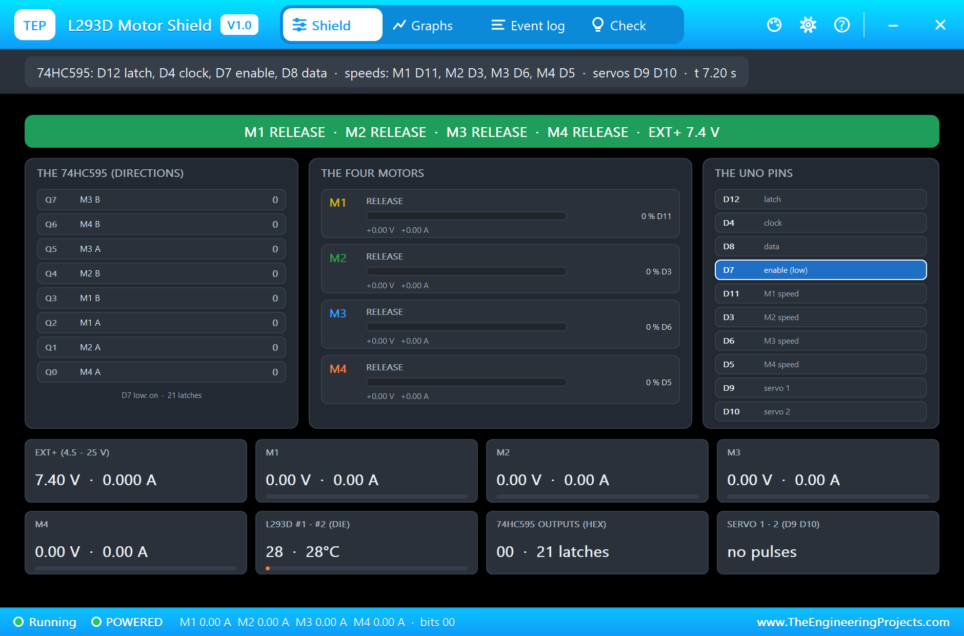
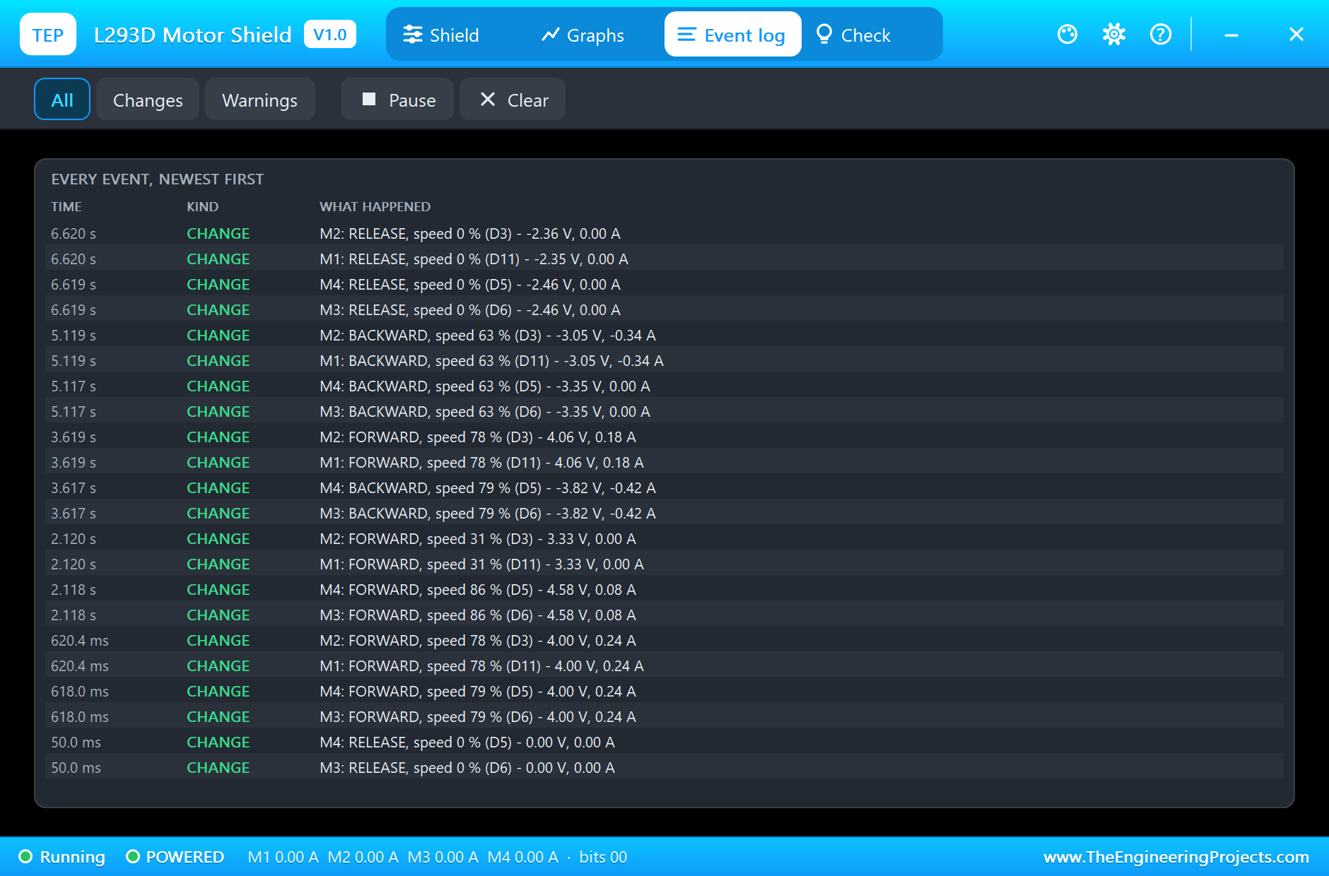
At 0.5 s the UNO sends all four motors forward at 200. The pop-up's 74HC595 card lights Q0, Q1, Q2 and Q5, the four A bits, and the tile reads 0x27, five latches so far: one to clear the register and one for each motor. Just after the start each motor takes 4.00 V and 0.24 A while it spins up, 0.746 A from EXT+ in all; at 1.5 s they run at 4.18 V and 0.06 A each, 0.183 A in all.
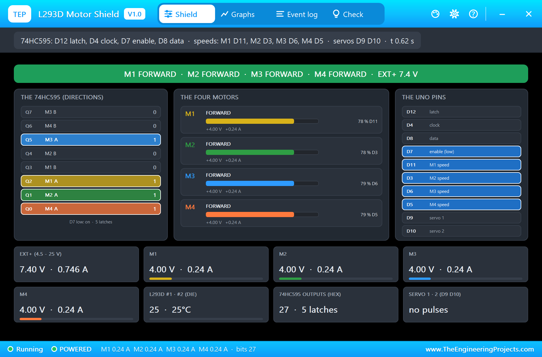
Compare the voltage with the supply: a speed of 200 is 78 % of 7.4 V, 5.8 V, but each motor gets only 4.18 V. The rest is lost in the L293D's two Darlington drops, exactly the price of this chip, and the simulation shows it on every motor. The speed bars also show a detail of the Arduino: M1 and M2 read 78 %, M3 and M4 79 %, because Timer2 and Timer0 count the same 200 slightly differently.
Turn Left and Spin Right
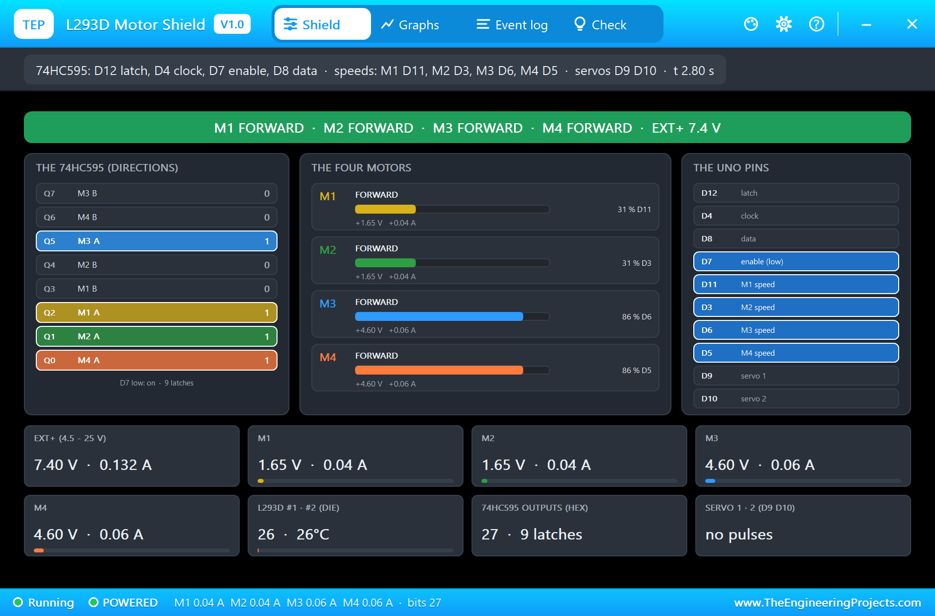
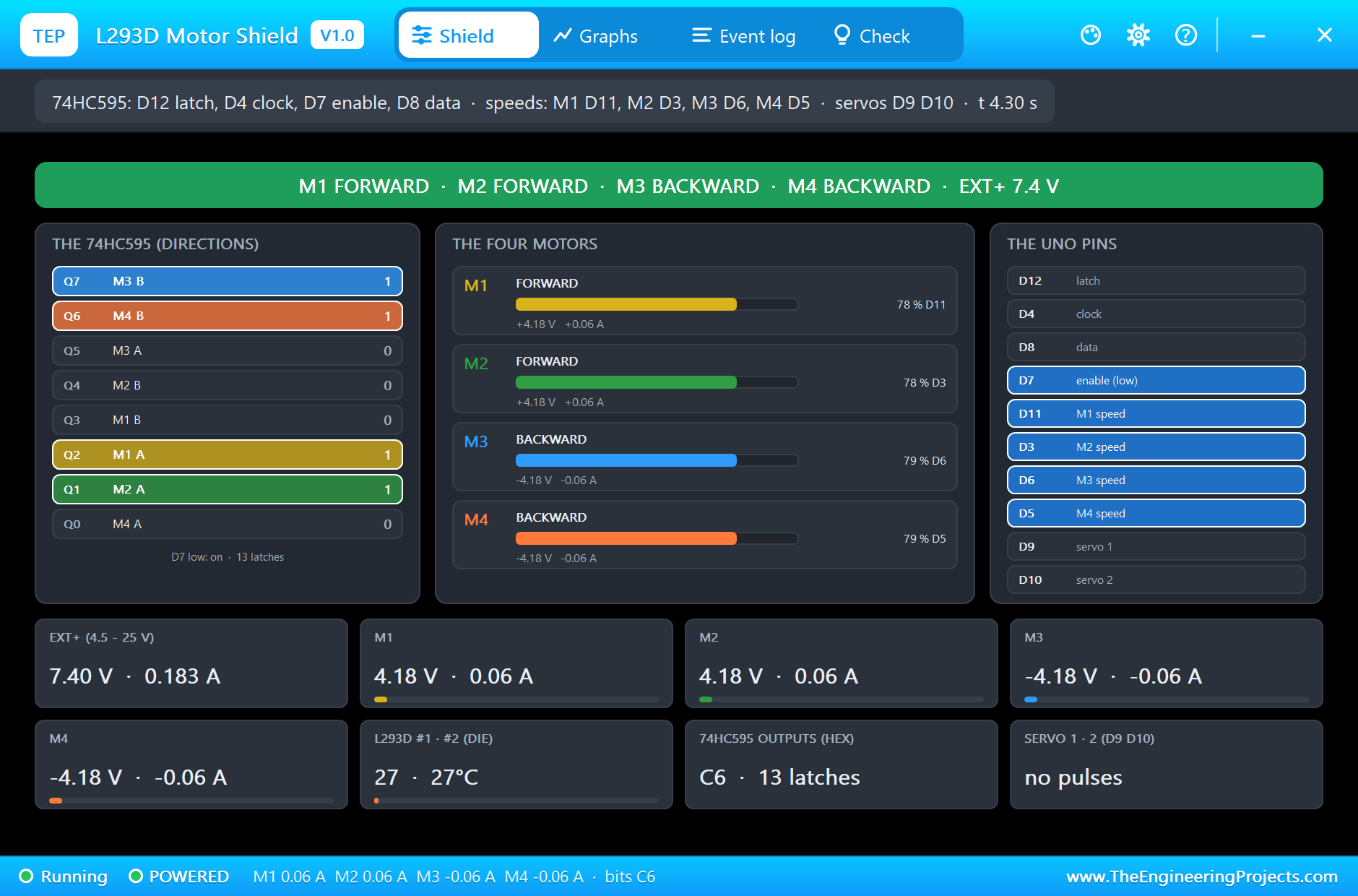
At 2 s the car turns left: the left wheels slow to 80, 31 %, and the right wheels speed up to 220, 86 %. The left motors now get 1.65 V at 0.04 A and the right motors 4.60 V at 0.06 A. The directions do not change, so the byte stays 0x27; only the four enables' PWM changes. At 3.5 s the car spins on the spot: the left wheels forward, the right wheels backward. M3 and M4 swap their A bits for their B bits, the byte becomes 0xC6, and the right motors' voltage turns negative.
Backward: a Reversal and a Coast
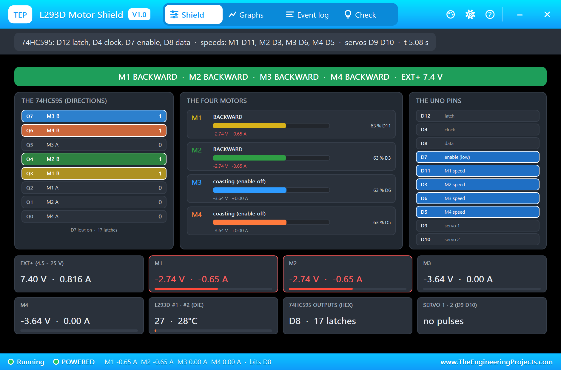
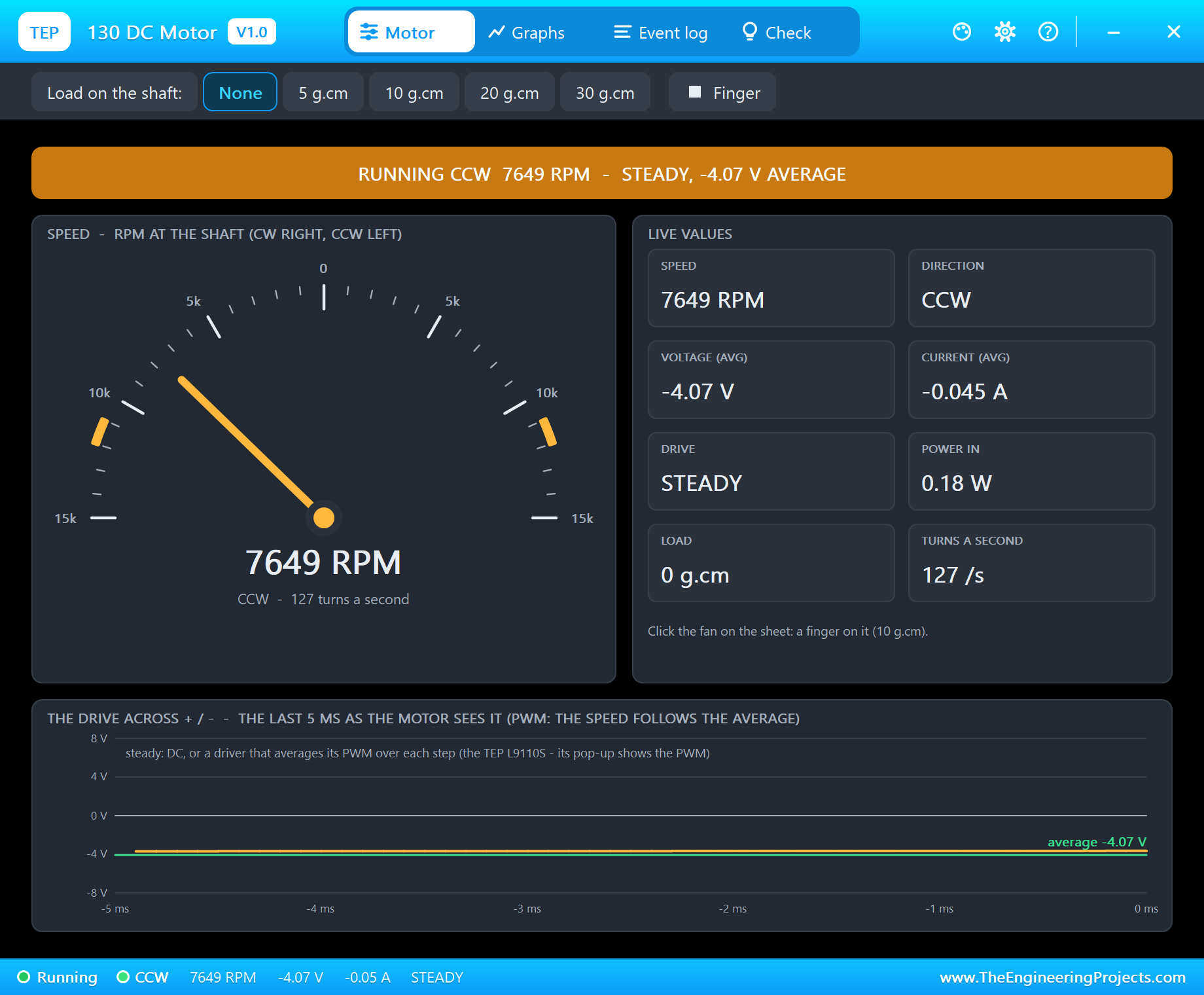
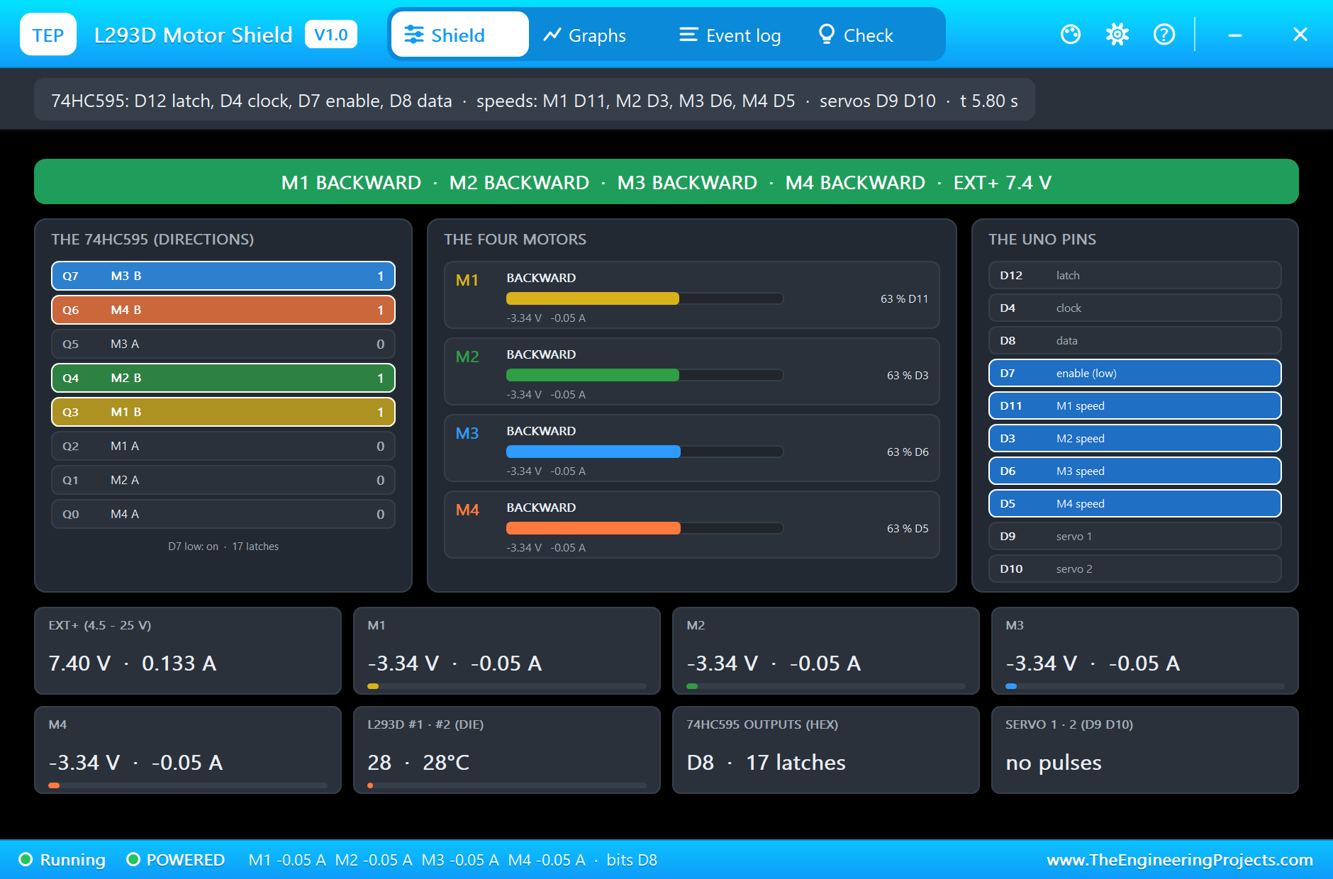
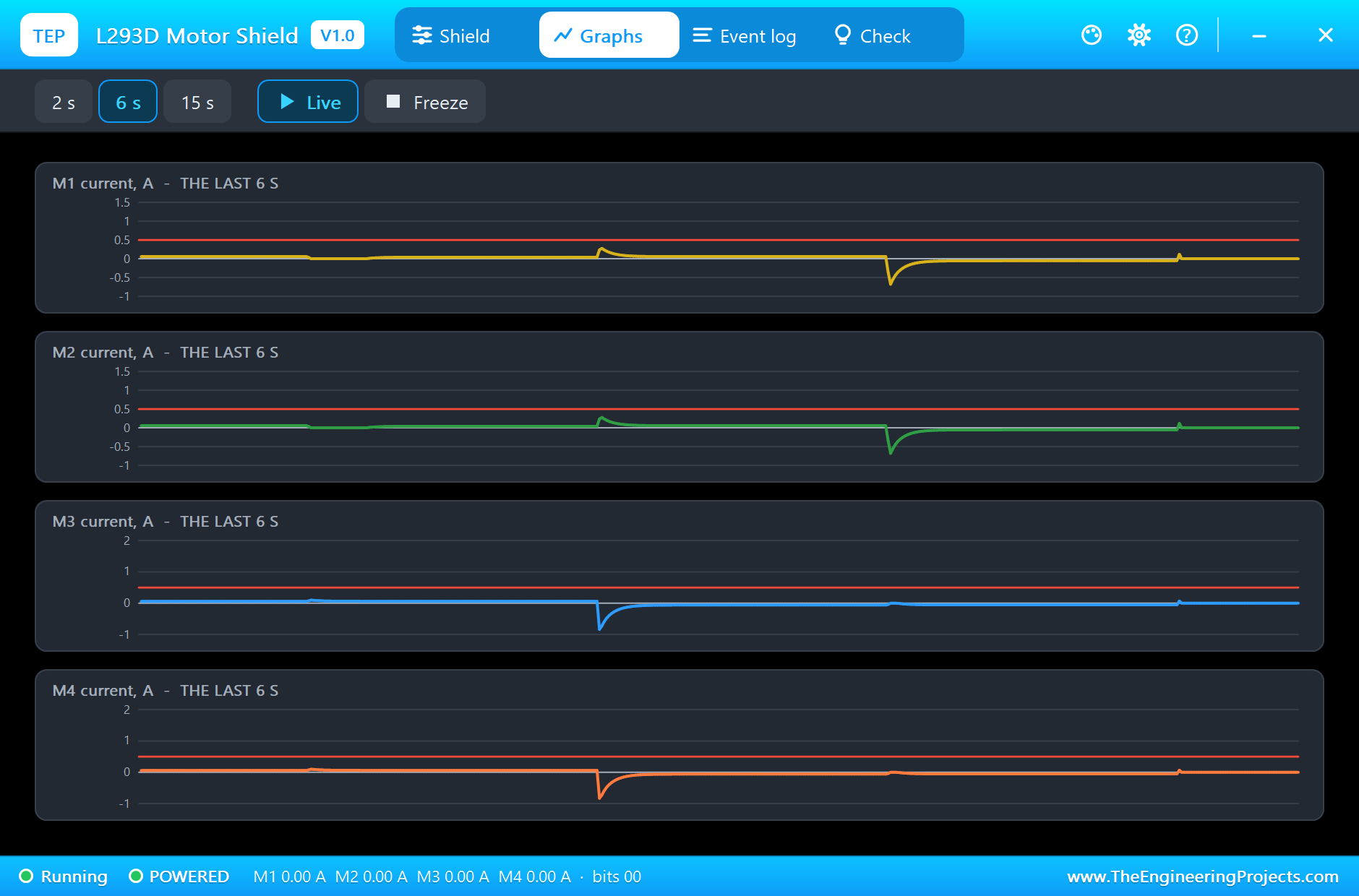
At 5 s all four go backward at 160: the byte becomes 0xD8, the four B bits. The two kinds of wheel behave differently, and the pop-up shows both. The left motors were turning forward and are reversed at once: for a moment their own back-EMF adds to the supply and they draw -0.65 A at -2.74 V, over the L293D's 600 mA continuous rating, so their tiles turn red. The right motors were already turning backward, faster than the new speed: the bridge cannot pull them down, its enable's off time leaves them open, and they coast down with -3.64 V of back-EMF and no current. At 5.8 s all four run at -3.34 V and -0.05 A.
Release
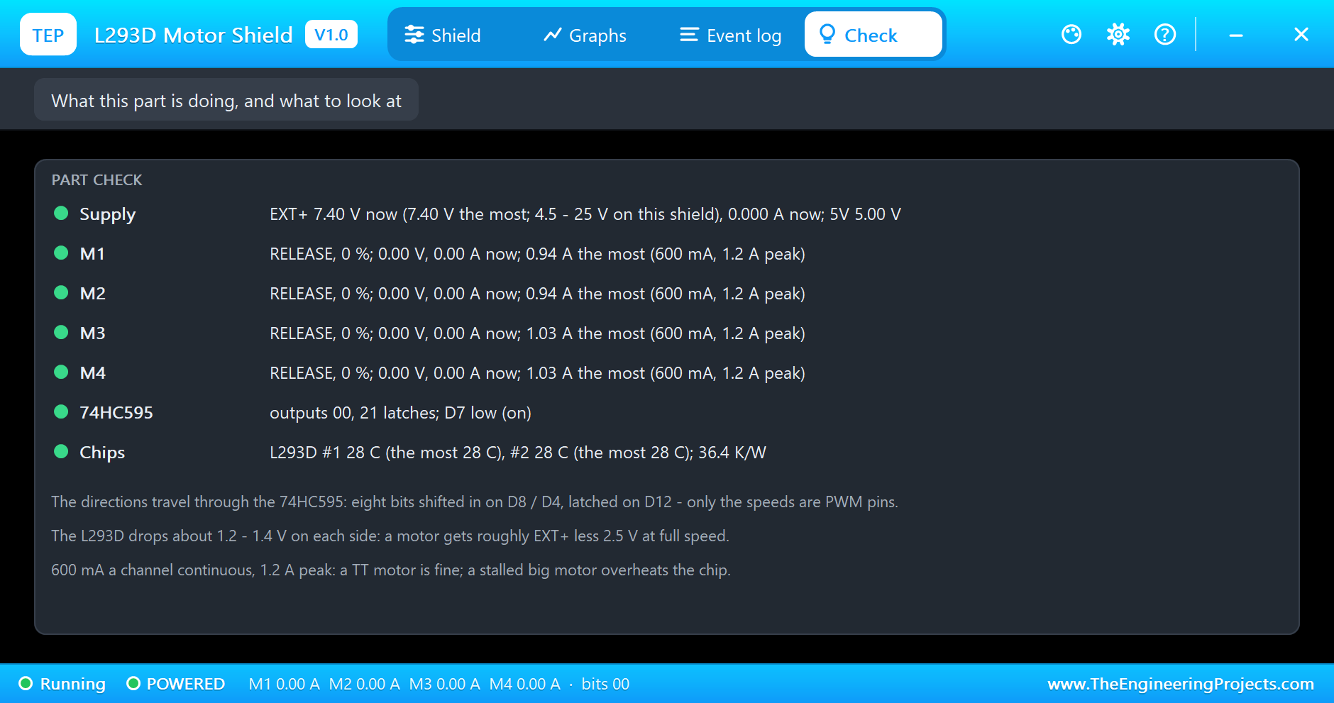
At 6.5 s the UNO releases all four: the byte goes to 0x00 and the speeds to 0, after 21 latches in all, one for every motor command. The motors coast to a stop. In the simulation both L293D chips have warmed only to 28 C: small motors like these are easy work for them.
The Graphs, the Event Log and the Check Page
The Graphs page plots the four motor currents over the last 2, 6 or 15 simulated seconds: the start, the turn, the spin and the reversal spike of the left wheels. The Event log keeps every motor command once it has held for 50 ms, with its direction, its speed pin and its voltage and current. The Check page sums up the supply, the four motors, the 74HC595 and the two chips at the end of the simulation.
Try It Yourself
- Type
m 1 255, thenm 1 -255: a full-speed reversal of one motor, and its current spike. - Lower EXT+ to 5 V: with the L293D's drops the motors get under 3 V and barely turn.
- Remove the latch pulse from latchTx(): the bits go into the register but the motors never see them.
- Write the bits LSB first instead of MSB first: the motors mix up, which shows why the order matters.
- Add a servo on D9 and drive it with the Servo library: the pop-up shows its pulse width on SER1.
Ideas to Extend the Demo
- Add an ultrasonic sensor on a free pin and stop the car before a wall.
- Drive two stepper motors instead of four DC motors: M1 + M2 and M3 + M4.
- Ramp every speed change, so a reversal never passes the 600 mA rating.
Your Own Sketches
The demo sketch is in the zip file, and you can change it in the Arduino IDE. New to Arduino? Start with our Arduino Tutorial for Beginners. Export the compiled binary, and set the UNO's PROGRAM property to the new file. Our guide on How to get the HEX file from Arduino shows you where the file ends up.
Things to Know Before Using a Real L293D Shield
- Expect the voltage drop: about 2.5 V lost in the L293D; a 6 V motor wants about 8.5 V on EXT+.
- Keep to 600 mA a channel: TT and 130 motors are fine; a big geared motor stalls far above it.
- The PWR jumper: on, the motors and the UNO share one supply; off, give the UNO its own supply and the motors EXT_PWR.
- Timer0 drives M3 and M4: changing its prescaler also changes millis() and delay().
Troubleshooting
- No motor turns: EXT+ is missing or under 4.5 V (the LED is off), or D7 is high.
- The directions do nothing: the 74HC595 needs its latch pulse on D12 after the eight clock pulses.
- A motor turns the wrong way: swap its two wires, or its A and B bits in the sketch.
- A motor runs at full speed or not at all: its enable is not driven with analogWrite.
- The part is not simulated:
TEPL293DSHIELD.DLLis missing from MODELS and from the project folder.
Limitations of the Simulation
- The enables' PWM is averaged: a real L293D's off time is a coast, so at part speed a lightly loaded motor turns a little faster than here.
- The L293D's drops are our fit (1.0 V plus 0.5 ohm a side) to the datasheet's typical figures; its switching times are not modelled.
- The thermal capacity and the 160 C shutdown are our figures; the datasheet gives 36.4 K/W.
- Arduino is a name of Arduino; this library is not made or endorsed by Arduino, Labcenter, Texas Instruments or any shield maker.
- Tested in Proteus 8.5 in November 2026 (the demo as shipped). Proteus 7 is not supported.
So, that was all about the L293D Motor Shield Library for Proteus Simulation. I hope it helps you understand in a simulation how this classic shield drives four motors from so few pins: the eight bits through the 74HC595, the four speeds on the L293D enables, and the voltage the Darlington drivers keep for themselves, with a pop-up that shows every bit and every motor. If you have any questions, ask in the comments and I will help you out. Till the next tutorial, take care and have fun!

Comments
0