


3-Phase PM Generator Library for Proteus V1.0 (Arduino, INA219)


Hello friends, I hope you all are doing great. Today, I am going to share the new 3-Phase PM Generator Library for Proteus V1.0, the third part of our renewable energy series. Open up almost any small wind turbine, water turbine or hand-crank charger and you will find the same part inside: a 3-phase permanent-magnet generator (PMG) - a ring of magnets turning inside a ring of coils, with three wires coming out, usually yellow, green and blue.
3-Phase PM Generator Library for Proteus
Latest version: V1.0 (November 2026, this tutorial)
Helping Tools
- Serial Monitor Advance: a serial terminal window for the UART of your board
- Serial Monitor Expert: the serial monitor with extra debugging tools
- LCD Library for Proteus V3.0: 16x2, 20x4 and I2C LCDs to show your readings
This library puts that generator into Proteus, together with the 3-phase rectifier board that turns its AC into DC. Its three phases are real AC: their voltage and their frequency both follow the speed, and the current you take brakes the shaft. And it has a SHAFT pin: wire a turbine to it and the turbine, the generator and the load are simulated together - which is exactly what our next library, the vertical-axis wind turbine, will do. The demo turns it with a built-in bench motor and measures it from an Arduino UNO V4.0.
NOTICE: a generator looks like a motor with three wires - and in a simulation it is often just a voltage source. Our team put a lot of effort into building one that behaves like the real thing: three phases with their resistance and inductance, a torque that grows with the current, a shaft that slows down when nothing drives it, and a pop-up that shows the phases live. Your feedback is the fuel that keeps us going, so please tell us what you think in the comments below or in the Motor Driver board of our forum. And if our free libraries help you, you can buy us a coffee. So, let's get started with the 3-Phase PM Generator Library for Proteus V1.0:
What is a 3-Phase PM Generator?
A permanent-magnet generator has no brushes and no field winding. Its rotor carries magnets - north and south poles in turn - and its stator carries the coils. As the rotor turns, each magnet sweeps past each coil and induces a voltage. The coils are wired as three phases, 120 degrees apart, so the generator gives three sine waves. Small ones like this are the heart of small wind and water turbines because they are simple, sealed and efficient.
| The 3-phase PM generator (the model) | |
|---|---|
| Poles | 12 (6 pole pairs), 18 coils, the three phases in star |
| EMF | 12 V rms between the lines at 600 RPM |
| Frequency | the RPM x 6 / 60: 60 Hz at 600 RPM |
| Rating | about 20 W at 600 RPM into a rectifier; 1.3 A rms a line |
| Windings | 0.6 ohm and 1.2 mH a phase |
| Properties | DRIVE (BENCH or SHAFT), RPM, AMBIENT |
The Speed Sets the Volts and the Frequency
A generator's voltage is not fixed like a battery's. Each magnet that passes a coil induces a voltage proportional to how fast it passes, so double the speed and you double the voltage. The frequency follows the speed too: with 6 pole pairs, each turn of the shaft gives 6 electrical cycles, so 600 RPM is 10 turns a second and 60 Hz. That is why a wind generator always needs a rectifier and a controller - its output is AC whose voltage and frequency change with the wind.
The Current Brakes the Shaft
Energy is not free: every watt the generator gives must come from the shaft. The current in the windings makes a torque that opposes the rotation - the harder you load the generator, the harder it is to turn. Short its three phases and it brakes so hard that small wind turbines use exactly this as their brake. The model computes this torque from the currents at every step.
What's New in 3-Phase PM Generator Library for Proteus V1.0
- Two parts, each just the component: the finned aluminium generator with its shaft and its three coloured wires, and the green 3-phase rectifier board with its diodes and capacitor.
- Real three-phase AC: three sinusoidal EMFs with each phase's resistance and inductance, at the frequency the speed sets.
- A SHAFT pin: the shaft is a net of its own (1 V = 1 RPM, 1 A = 1 N.m), so a turbine library can drive the generator and the whole chain is solved together.
- A bench motor: for its own tests the generator can be turned at 200, 400, 600 or 900 RPM from its pop-up.
- A pop-up window with four pages - Generator, Graphs, Event log and Check - with the three phases drawn live and a cut-away of the magnets turning past the coils.
- An A3 demo on our Arduino UNO V4.0: the speed measured from the AC itself, and the DC volts, amps and watts from our INA219.
The 3-Phase PM Generator in Proteus
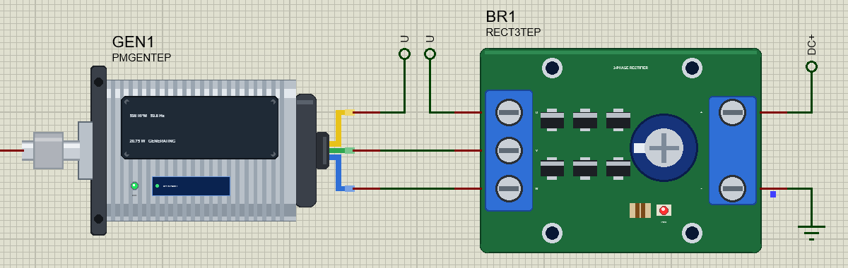
Search generator in Pick Devices; the device PMGENTEP is in TEPPMGEN.LIB (category Electromechanical, Renewable Energy) and its model is TEPPMGEN.DLL. The symbol is the generator seen from the side: the steel shaft and its coupling on the left (the SHAFT pin), the front flange with its mounting holes and its bearing, the finned aluminium body, the back cap and the cable gland with the yellow, green and blue phase wires leading to the U, V and W pins.
At Run the coupling's key mark turns with the shaft. On the body, the nameplate's value line shows the RPM, the frequency, the watts and the state; the OUT LED lights green while the generator delivers power; and OPEN PANEL opens the pop-up. The value line, the LED and the button are TEP additions; a real generator has none of them.
The Pins and the Properties
| Pin | What the model does with it |
|---|---|
| U, V, W | the three phases (yellow, green, blue): the AC out |
| SHAFT | the shaft: 1 V on its net = 1 RPM, 1 A into it = 1 N.m driving it |
| Property | Default | What it does |
|---|---|---|
| DRIVE | BENCH | BENCH: the built-in test motor turns the shaft; SHAFT: only the SHAFT pin's net does |
| RPM | 600 | the bench motor's speed at the start (0 to 1200) |
| AMBIENT | 25 | the air in C; the winding starts at it and warms with its losses |
The 3-Phase Rectifier Board
The second device, RECT3TEP, is the small green board sold for brushless and wind generators: a blue 3-way input terminal, six Schottky diodes (0.45 V at 1 A), a 2200 uF filter capacitor (property CAP), a red power LED and a 2-way output terminal. Two diodes conduct at any moment - the phase that is highest to + and the lowest to -, so the output is the top of the three line voltages. That ripples six times per electrical cycle, and the capacitor smooths it.
The SHAFT Pin
Proteus only simulates electrical circuits, so the shaft is carried on an electrical net: the speed is the voltage of the SHAFT net (1 V for every RPM) and the torque is the current into it (1 A for every N.m). A turbine model pushes current into the net, the generator takes it out as its braking torque, and the rotor's inertia acts as a capacitor. Put a Proteus voltmeter on the SHAFT net and it reads the RPM. In this demo the SHAFT pin stays free, because the bench motor turns the generator.
Download 3-Phase PM Generator Library for Proteus
Click the button below to download 3-Phase-PM-Generator-Library-for-Proteus-v1.0.zip (about 1.2 MB, without the source code of the models):
3-Phase PM Generator Library for Proteus V1.0- README.txt: installation, the demo, the wiring, the properties, real hardware, troubleshooting and the limits.
- Proteus Library Files:
TEPPMGEN.LIB(both devices) andArduinoV4TEP.LIBfrom our Arduino Library for Proteus V4.0. - Proteus Model Files:
TEPPMGEN.DLLandTEPARDUINO.DLL. - Proteus Simulation:
3-Phase-PM-Generator-Rectifier-INA219-ArduinoUnoV4.pdsprj,PMGen_Demo.hexand copies of the DLLs. - Arduino Code:
PMGen_Demo.ino(only the Wire library of the Arduino core).
Good to know: the demo's INA219 and its DC electronic load are our INA219 Current Sensor library, a separate download that is not in this zip. Get it from its own article, the INA219 Current Sensor Library for Proteus, and install TEPINA219.LIB and TEPINA219.DLL the same way.
No Proteus yet? Read How to Download and Install Proteus 7 and 8. New to libraries? Follow How to Install a New Library in Proteus.
How to Install 3-Phase PM Generator Library for Proteus
- Close Proteus and extract the whole zip file, for example to your Desktop.
- Copy
TEPPMGEN.LIBandArduinoV4TEP.LIBfrom Proteus Library Files into the LIBRARY folder of Proteus (usuallyC:\Program Files (x86)\Labcenter Electronics\Proteus 8 Professional\LIBRARY). - Copy
TEPPMGEN.DLLandTEPARDUINO.DLLfrom Proteus Model Files into the MODELS folder. The two Arduino files are the ones of our Arduino Library V4.0; if you have it, they are the same. - Install the INA219 Current Sensor library the same way if you do not have it yet.
- Delete
TEPPMGEN.IDXfrom the LIBRARY folder if it is there. - Start Proteus, press P and search for generator (or rectifier).
Tip: keep the Proteus Simulation folder together, because the project needs its .hex file and the DLLs beside it. The library is tested in Proteus 8.5; Proteus 7 is not supported.
The Demo Circuit
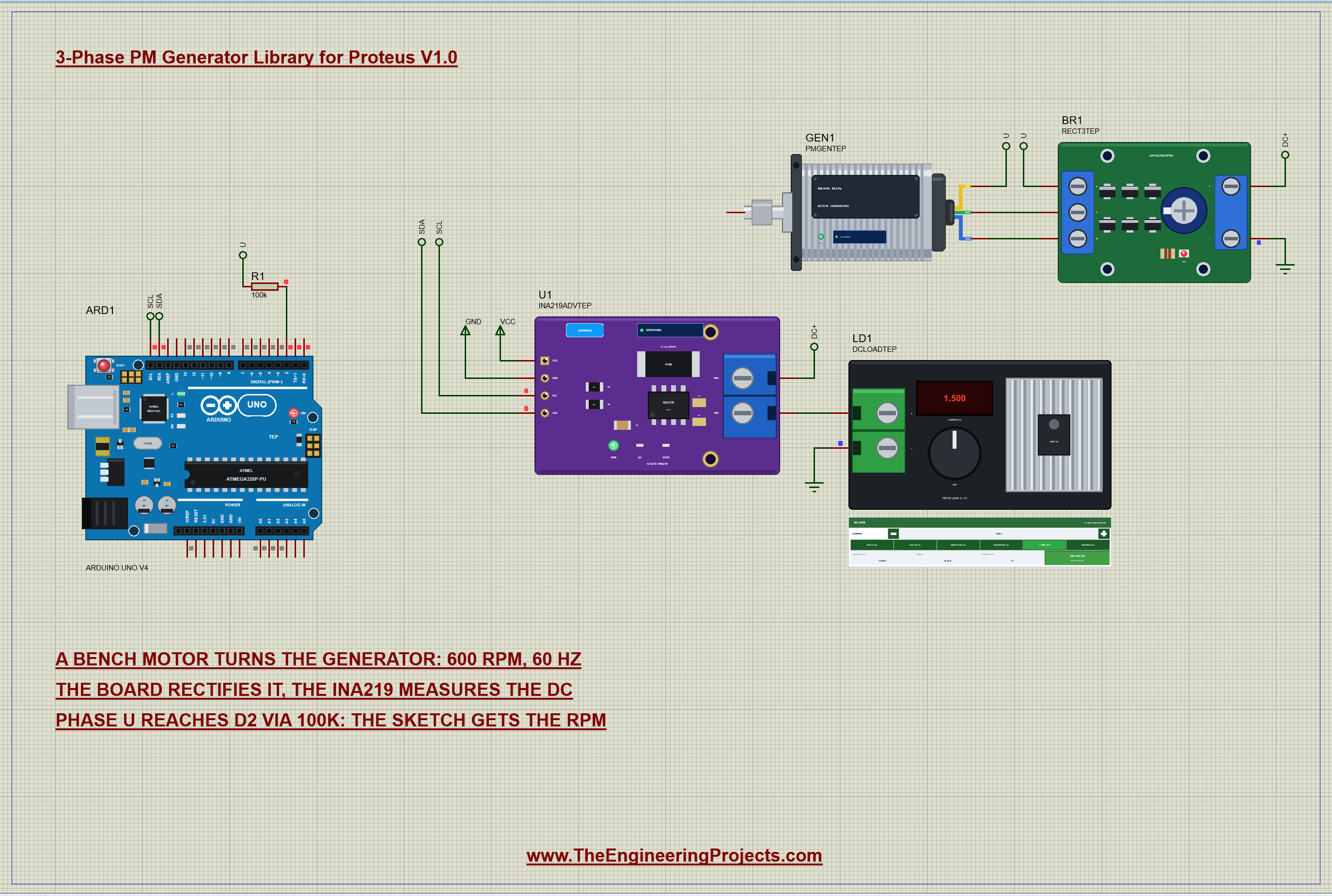
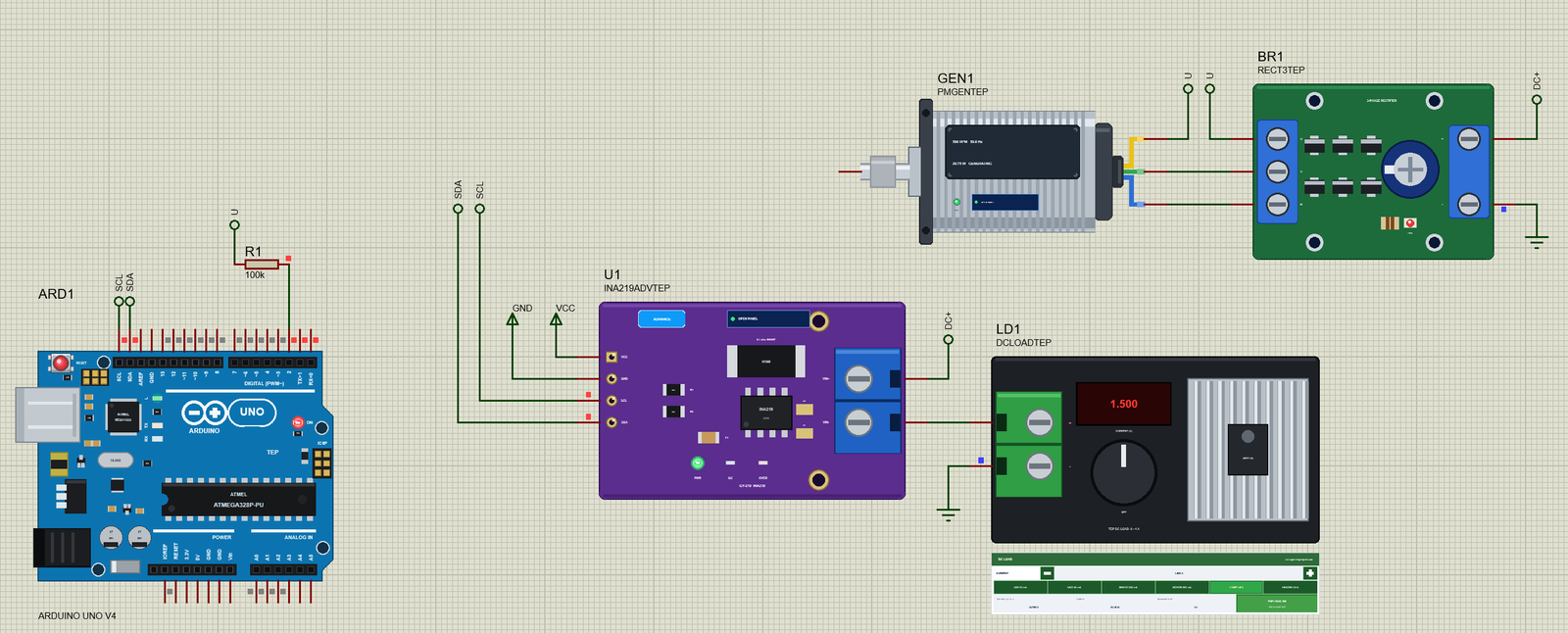
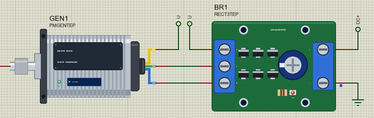
Open 3-Phase-PM-Generator-Rectifier-INA219-ArduinoUnoV4.pdsprj. ARD1 is an Arduino UNO V4.0 from our Arduino UNO Library for Proteus V4.0, running PMGen_Demo.hex with its serial monitor built in. GEN1 is the generator, turned by its bench motor at 600 RPM. Its V and W phases run straight into the rectifier board BR1; U goes by labels, because it also feeds R1. The board's + goes through U1, our INA219 in its pop-up version, into LD1, the INA219 library's electronic load, set to 1.5 A - the generator's rated load at 600 RPM.
| Part | Pin | Goes to |
|---|---|---|
| GEN1 | V, W | BR1's V and W (straight wires) |
| GEN1, BR1, R1 | U | the U label: one net |
| BR1 | + | the DC+ label, which joins the INA219's VIN+ |
| INA219 | VIN- | the DC load's + (a straight wire) |
| INA219 | SDA, SCL | the UNO's A4 and A5 (SDA and SCL labels) |
| R1 (100k) | the other end | the UNO's D2 |
| BR1, LD1 | - | ground |
Why a Rectifier, an INA219 and a DC Load?
Most projects need DC from a generator - to charge a battery or to run electronics - so the demo turns its AC into DC with the rectifier board, exactly like a small wind turbine does. The INA219 then measures the DC volts and the real current through its 0.1 ohm shunt, and the DC electronic load draws exactly the current you set, so you can load the generator lightly, at its rating or beyond it. The speed is taken from the AC itself: phase U reaches the UNO's D2 through R1.
The Arduino Code
The sketch needs only the Wire library of the Arduino core. New to Arduino? Start with Arduino Tutorial for Beginners and Introduction to Arduino UNO. It starts with the INA219's address, its shunt, the speed input and the generator's pole pairs:
const byte INA = 0x40;
const float SHUNT_OHM = 0.1;
const byte TACH = 2;                          // INT0: phase U through 100k
const byte POLE_PAIRS = 6;
The Speed from the AC
Phase U swings from just below 0 V to the DC output and back once per electrical cycle, so every rising edge on D2 is one cycle. On a real board the AVR's input clamp diodes keep the pin inside 0 to 5 V and the 100k resistor keeps their current tiny - Atmel's application note AVR182 detects mains zero crossings the same way. The interrupt only keeps the times of the last nine edges:
void onEdge() { edgeUs[edgeAt] = micros(); edgeAt = (edgeAt + 1) % 9; if (edgeCount < 9) edgeCount++; }From those times the sketch takes the frequency over the last eight whole cycles - exact, and recent - and compares the first four cycles with the last four. If they disagree, the speed is changing:
  const unsigned long first = middle - oldest, last = newest - middle;
  steady = labs((long)first - (long)last) < (long)(last / 50) + 200;
  return 8e6 / (newest - oldest);
Then the RPM is the frequency times 60, divided by the pole pairs:
const float rpm = hz * 60 / POLE_PAIRS;Our first test run measured the frequency over the whole report interval instead. When the bench motor sped up in the middle of an interval, the speed came out as an average of the old and the new one, while the volts were already the new ones - the best point was saved with a wrong RPM. Timing only the latest cycles fixed it.
The DC Side
A rectified 3-phase supply ripples at six times the AC frequency, 360 Hz at 600 RPM. A single INA219 reading catches it at some random point of that ripple, so the sketch takes 16 readings about 1.2 ms apart and averages them:
  for (byte k = 0; k < 16; ++k) {
    const long b = (uint16_t)readReg(0x02) >> 3;  // 4 mV a step
    if (k < 8) bus1 += b; else bus2 += b;
    shunt += readReg(0x01);                       // 10 uV a step
    delayMicroseconds(1100);
  }
The first eight and the last eight bus readings are compared as well: a reading taken while the load or the speed changes is marked and does not count for the best point. The current is the shunt volts over 0.1 ohm, and the board's own volts are the bus plus the shunt's drop:
  amps = shuntV / SHUNT_OHM;
  volts = (bus1 + bus2) / 16.0 * 0.004 + shuntV;  // the board's own volts: the bus plus the shunt's drop
The Report Loop
Every second the sketch prints the speed, the frequency, the DC volts, amps and watts, with a note when the reading is changing, the shaft has stopped or nothing takes the power:
  if (!steady) Serial.print(F("  - changing"));
  else if (rpm < 5) Serial.print(F("  - stopped"));
  else if (amps < 0.002) Serial.print(F("  - no load"));
rate 500 changes the interval (200 to 5000 ms), best prints the best point so far and reset forgets it. The sketch also writes the INA219's calibration register once, so the chip's own Current and Power registers work too:
writeReg(0x05, 4096); // the calibration: 0.1 mA a step in the Current registerThe HEX file is in the package. To change the sketch, open it in the Arduino IDE and export the compiled binary, as in How to get the HEX file from Arduino. It needs 10,188 bytes of flash (31 % of the UNO) and 538 bytes of RAM.
Running the Demo
Press Run. The UNO's serial monitor, the generator's pop-up and the INA219's pop-up open over the schematic; move them aside. The bench motor spins the generator up to 600 RPM in about a second, and the sketch introduces itself:
3-Phase PM Generator demo - The Engineering Projects
Phase U on D2 gives the speed; the INA219 (0x40 on A4 / A5) measures the rectifier board's DC output.
Commands: best | reset | rate 1000 | help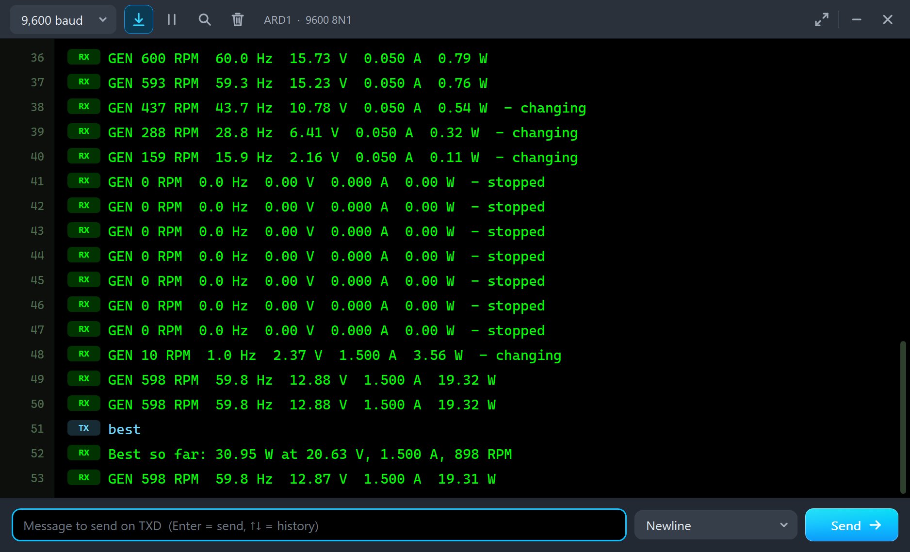
At the Rated Point
At 600 RPM with the load at 1.5 A, the generator works at its rating: "GENERATING - 598 RPM (59.8 Hz): 10.63 V x 1.208 A rms, 20.70 W out of 24.33 W in (85 %)". The first numbers are on the AC side: the line volts and the line current, rms. The power out of the shaft is the power in less the copper losses, the bearings and the cogging.
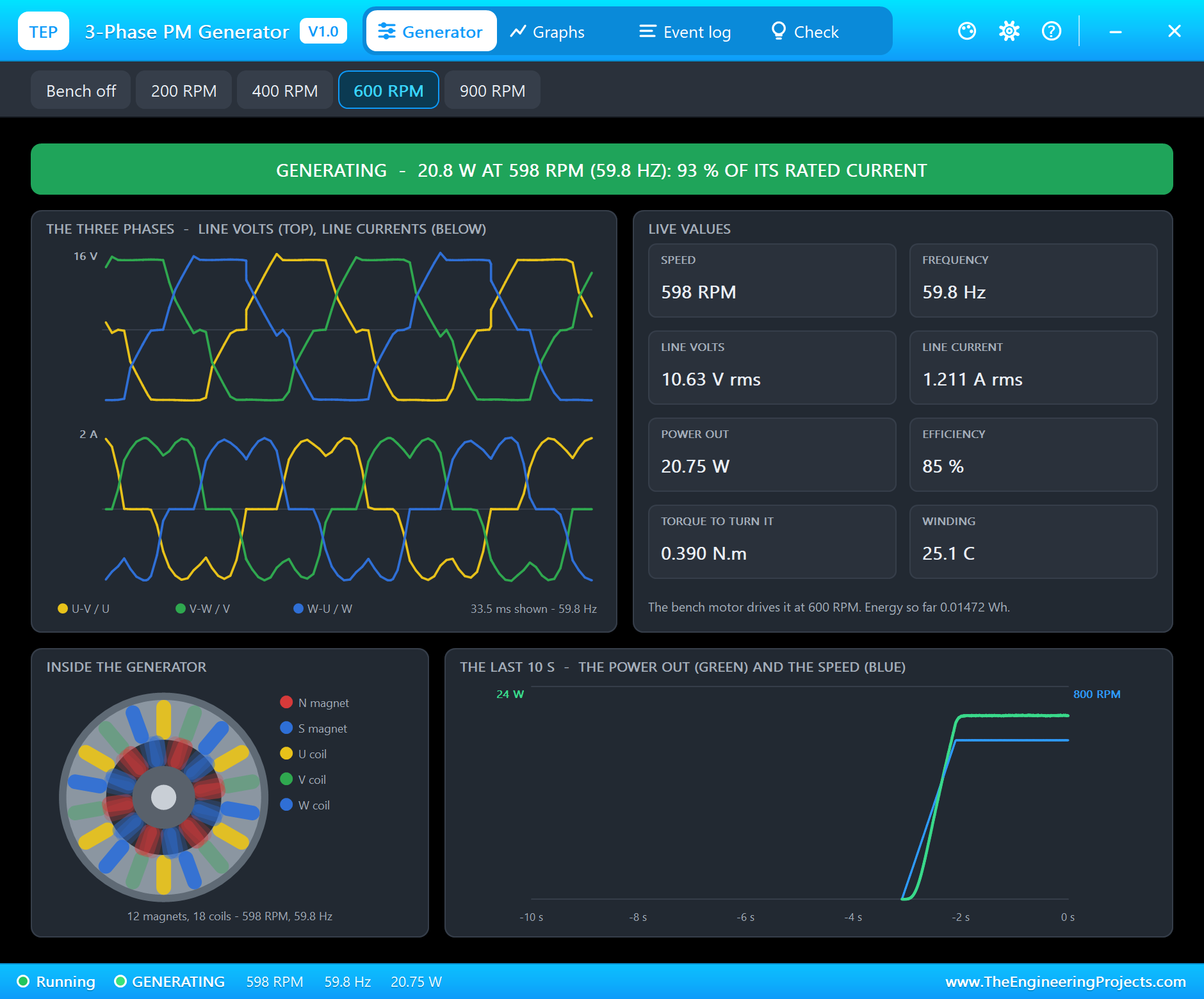
The pop-up has the look of our TEP Serial Monitor Advance for Proteus and four tabs: Generator, Graphs, Event log and Check. The left card draws the three phases live - the line voltages on top and the line currents below - over the last two cycles. The voltages are no longer clean sine waves: the rectifier clips their tops while its diodes conduct, and the currents come in pulses. Below them, INSIDE THE GENERATOR shows the 12 magnets turning past the 18 coils, each coil as bright as its phase's current.
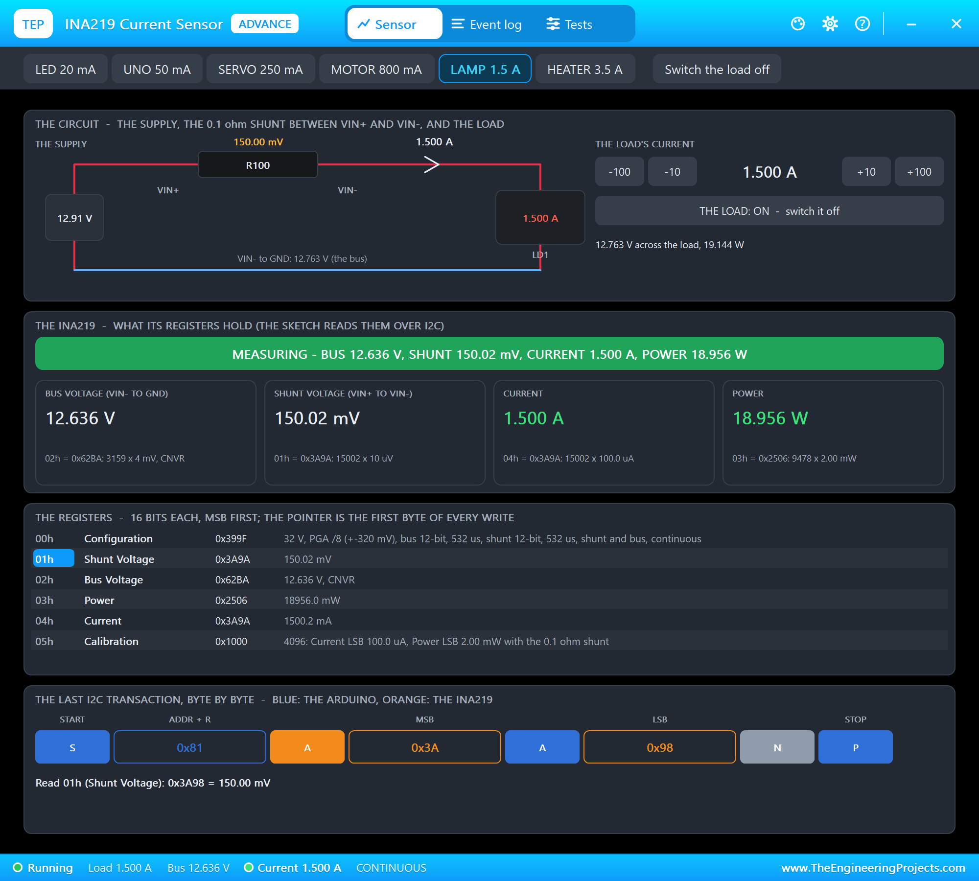
The INA219 sees the DC side: "MEASURING - BUS 12.636 V, SHUNT 150.02 mV, CURRENT 1.500 A, POWER 18.956 W". The monitor agrees: GEN 598 RPM 59.8 Hz 12.88 V 1.500 A 19.32 W. The difference between the AC power and the DC power is what the rectifier's diodes turn into heat - about 0.45 V each, two at a time.
A Light Load
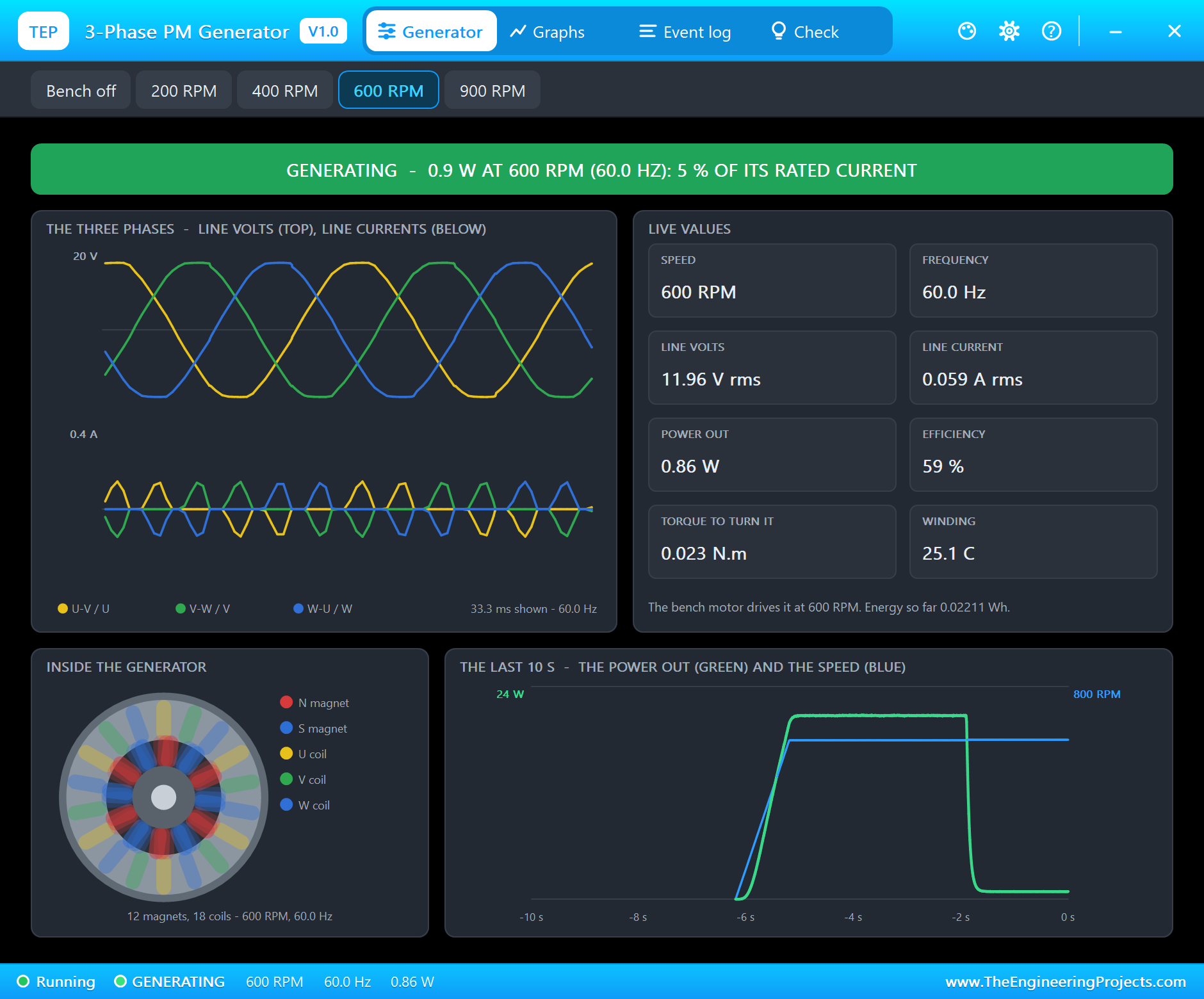
Click UNO 50 mA on the INA219's pop-up: "GENERATING - 600 RPM (60.0 Hz): 11.95 V x 0.059 A rms, 0.86 W out of 1.45 W in (59 %)". The voltage rises close to the EMF, because little current flows through the windings - and the efficiency drops, because the bearings and the cogging take almost as much as the load.
No Load
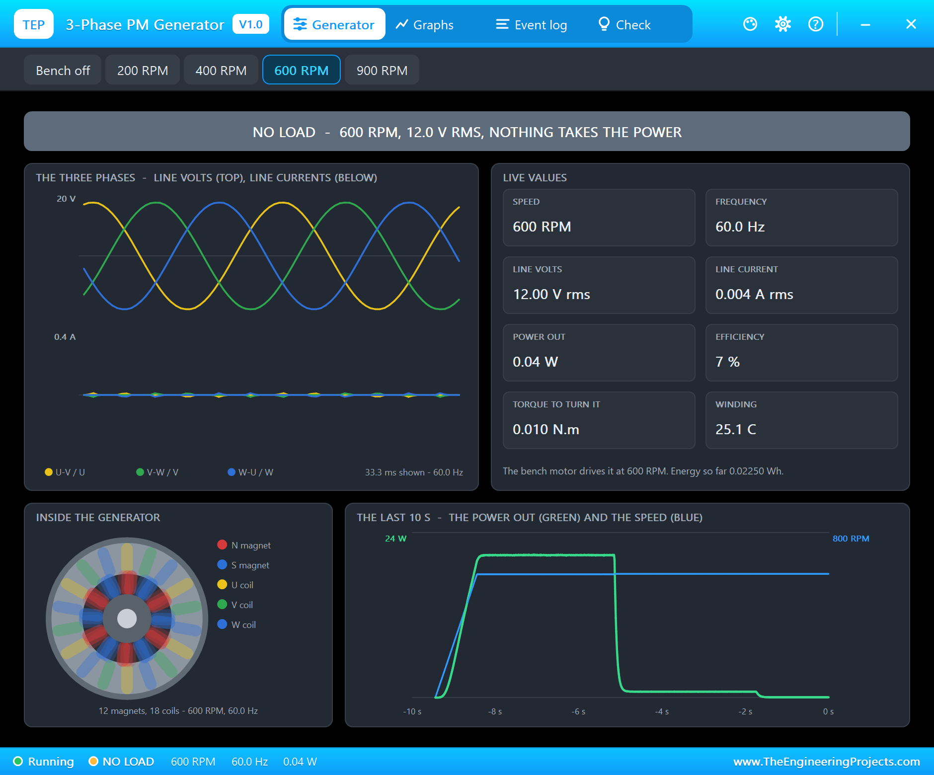
Click Switch the load off: "NO LOAD - 600 RPM (60.0 Hz): 12.00 V rms between the lines and no current". The line voltage is now the full EMF, the clean sine waves are back, and the board's capacitor charges to the peak of the line voltage: the run's log shows 16.29 V on its output.
An Overload
Switch the load back on, click LAMP 1.5 A and then +100 ten times: the load now wants 2.5 A. The generator gives it, but at a cost: "OVERLOAD - 1.97 A rms in each line, 151 % of the 1.3 A it is rated for: the winding heats (7.0 W lost)".
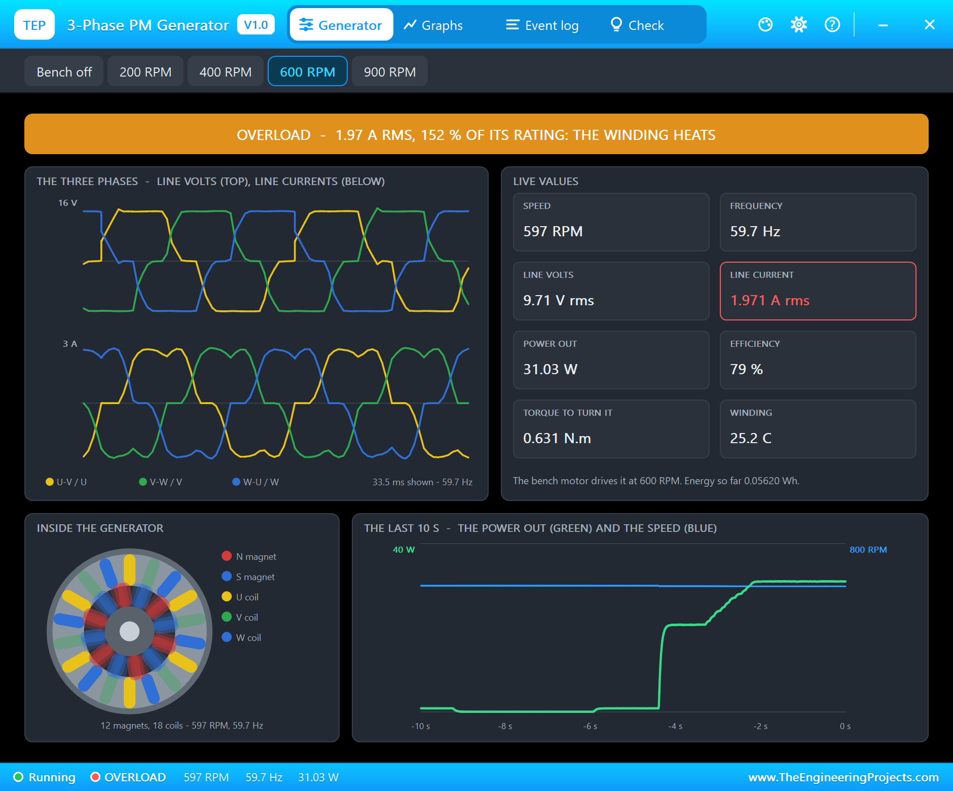
The power out is higher, but the voltage sags and the copper losses grow with the square of the current. The Check page shows it row by row: "1.97 A rms - 152 % of the 1.30 A it is rated for", "31.03 W out of 39.44 W from the shaft" and "79 % (copper 7.00 W, bearings and cogging 0.58 W)".
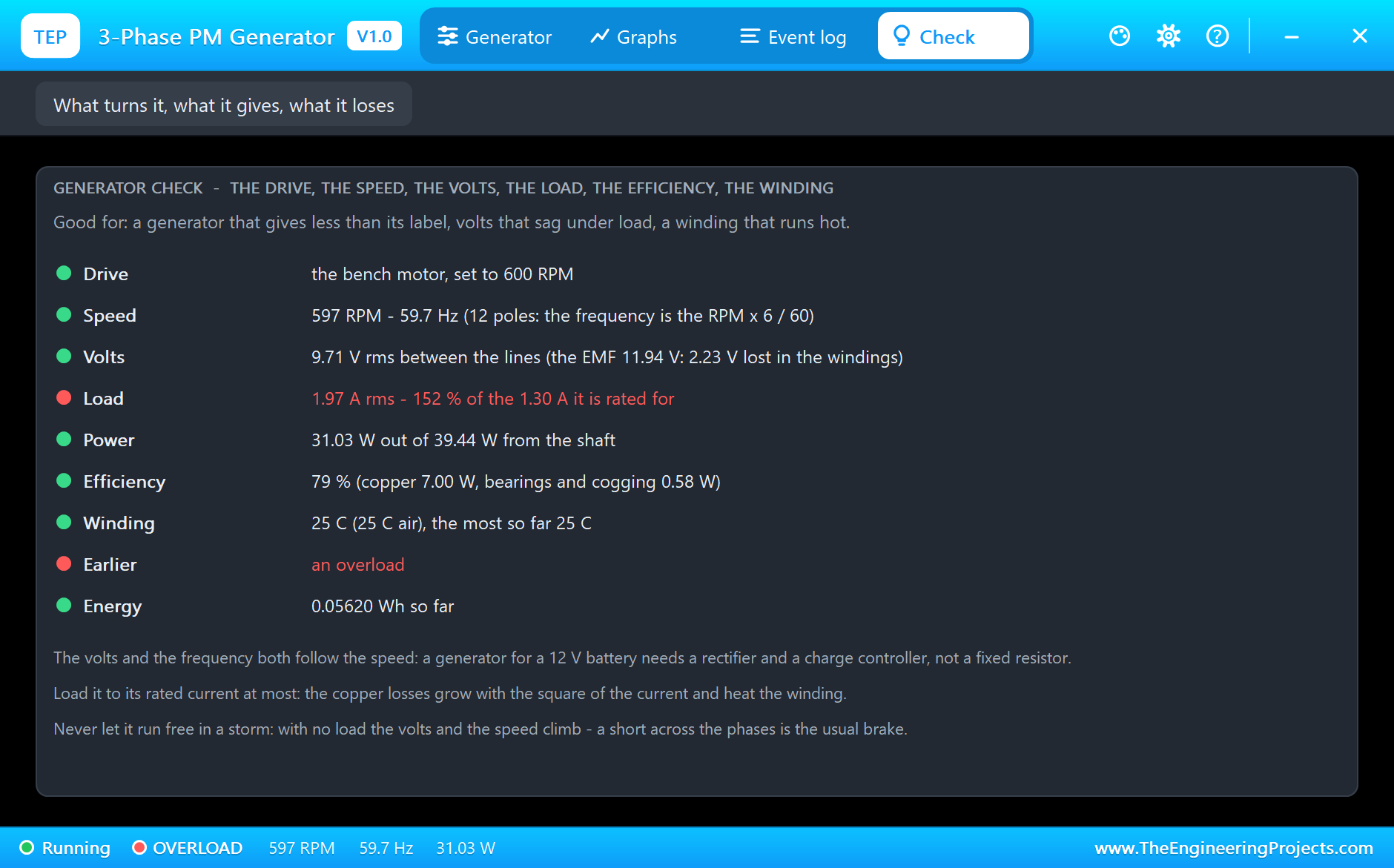
In this demo the overload only lasts a few seconds, so the winding hardly warms. Left for minutes, the copper losses would heat it until the pop-up warns HOT - which is why a generator's rating is about its current, not its speed.
Faster and Slower
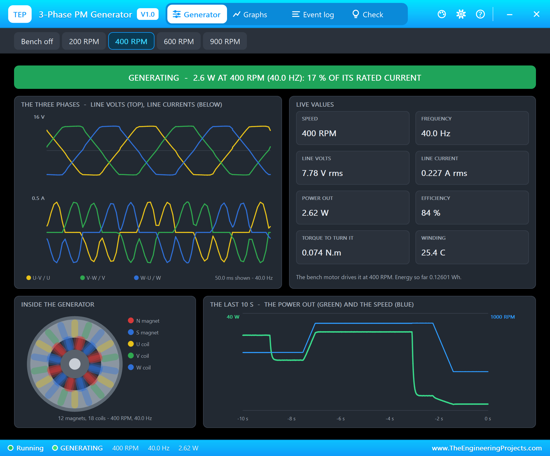
Back to LAMP 1.5 A, and click 900 RPM on the generator's pop-up. The bench motor speeds it up, and both the voltage and the frequency follow: "GENERATING - 898 RPM (89.8 Hz): 16.55 V x 1.213 A rms, 32.37 W out of 36.60 W in (88 %)".
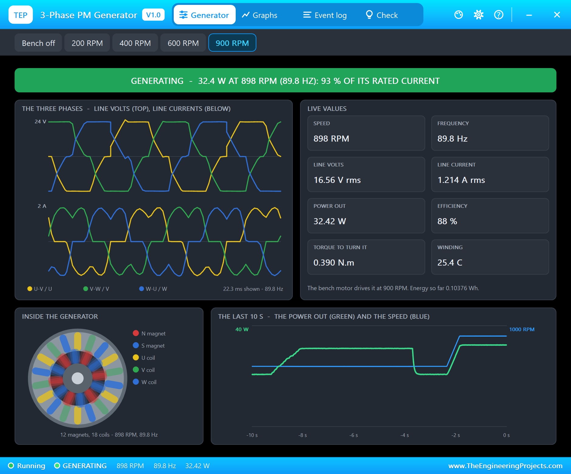
At the same current, the power rose by more than half - because the voltage rose with the speed. This is why a wind turbine's generator delivers so much more in a strong wind. Now click 400 RPM and SERVO 250 mA: "GENERATING - 399 RPM (39.9 Hz): 7.78 V x 0.228 A rms, 2.64 W out of 3.13 W in (84 %)".
Coasting to a Stop
With the load at UNO 50 mA and the bench back at 600 RPM, click Bench off. Nothing drives the shaft now: "THE BENCH MOTOR off (set on the panel) - the shaft is free: only the SHAFT pin can drive it now" and "COASTING - nothing drives the shaft: it slows down from 598 RPM".
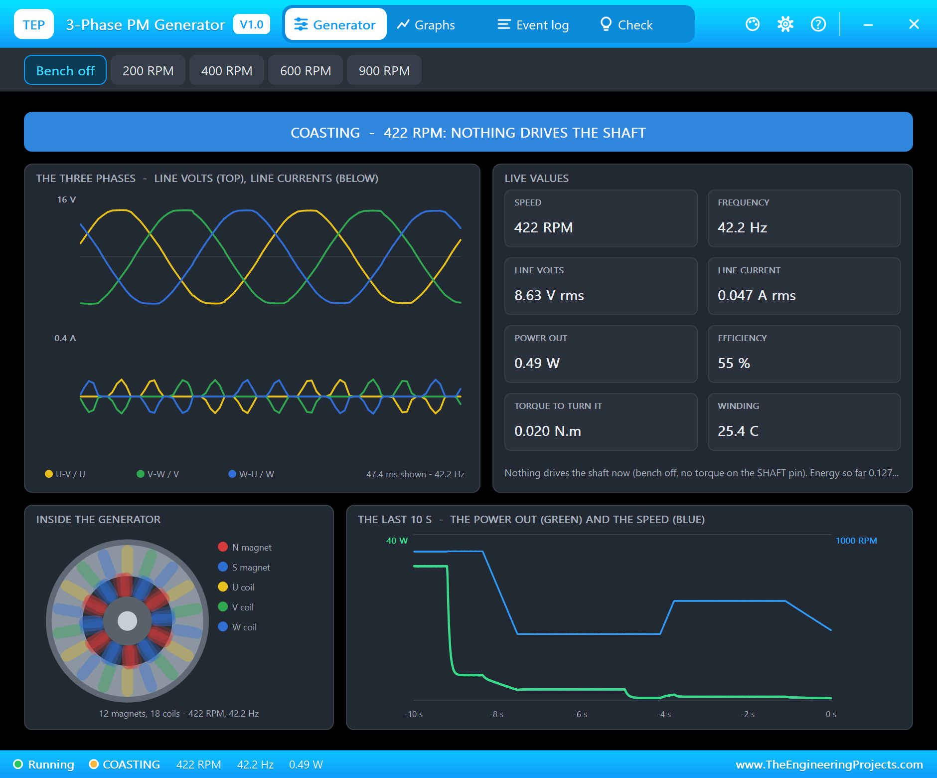
The rotor's inertia keeps it turning for a few seconds, the bearings, the cogging and the load slowing it down, and the voltage and the frequency fall with the speed until "STOPPED - the shaft is still: no voltage, no power". A heavier load stops it sooner: in our PC tests, with 0.5 A it was down to 300 RPM after 0.35 s and stopped after 1.22 s.
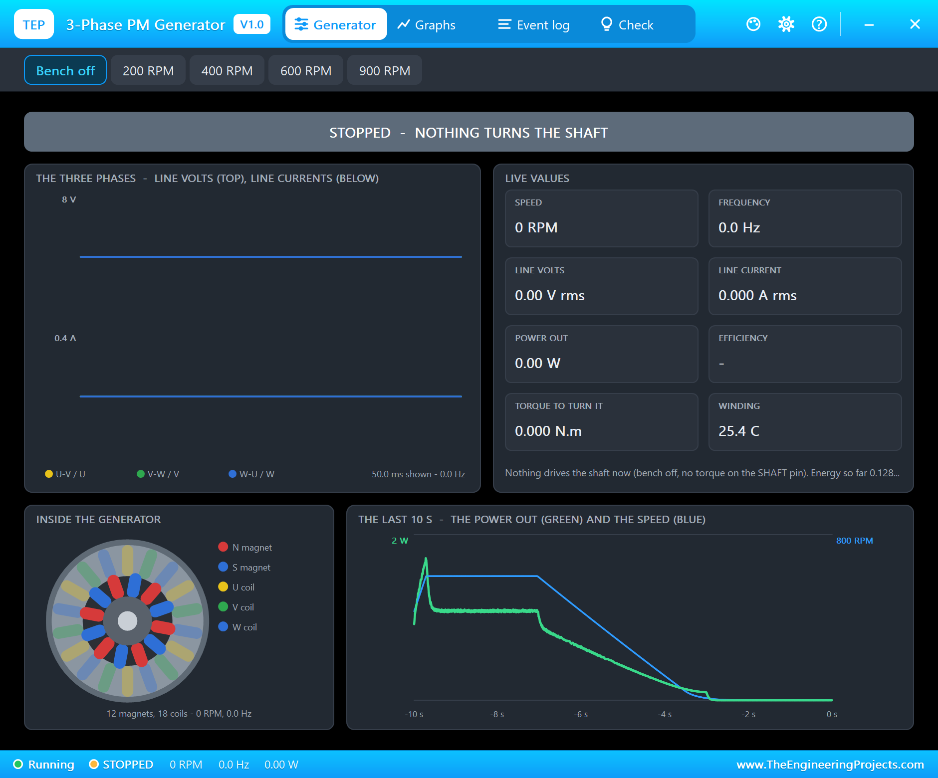
Back at 600 RPM with 1.5 A, the monitor shows the whole story - and the best point it saw:
GEN 593 RPM  59.3 Hz  15.23 V  0.050 A  0.76 W
GEN 437 RPM  43.7 Hz  10.78 V  0.050 A  0.54 W  - changing
GEN 159 RPM  15.9 Hz  2.16 V  0.050 A  0.11 W  - changing
GEN 0 RPM  0.0 Hz  0.00 V  0.000 A  0.00 W  - stopped
GEN 598 RPM  59.8 Hz  12.88 V  1.500 A  19.32 W
best
Best so far: 30.95 W at 20.63 V, 1.500 A, 898 RPM
Graphs and the Log
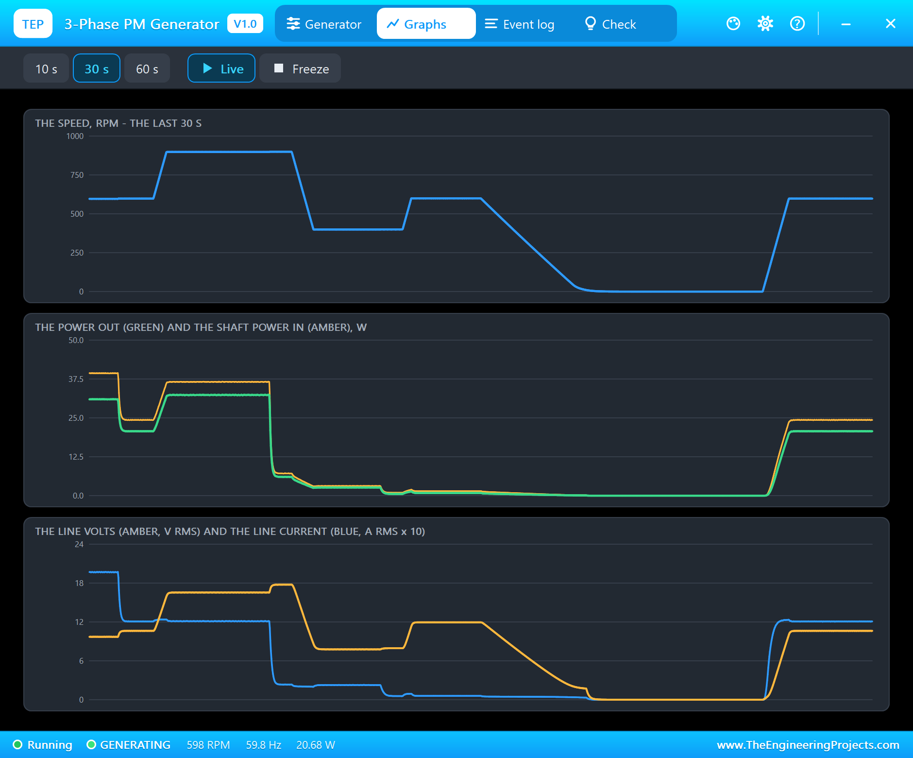
Graphs draws the speed, the power out against the shaft power in, and the line volts and current over the last 10, 30 or 60 seconds. The gap between the two power lines is the generator's losses; you can see it grow during the overload.
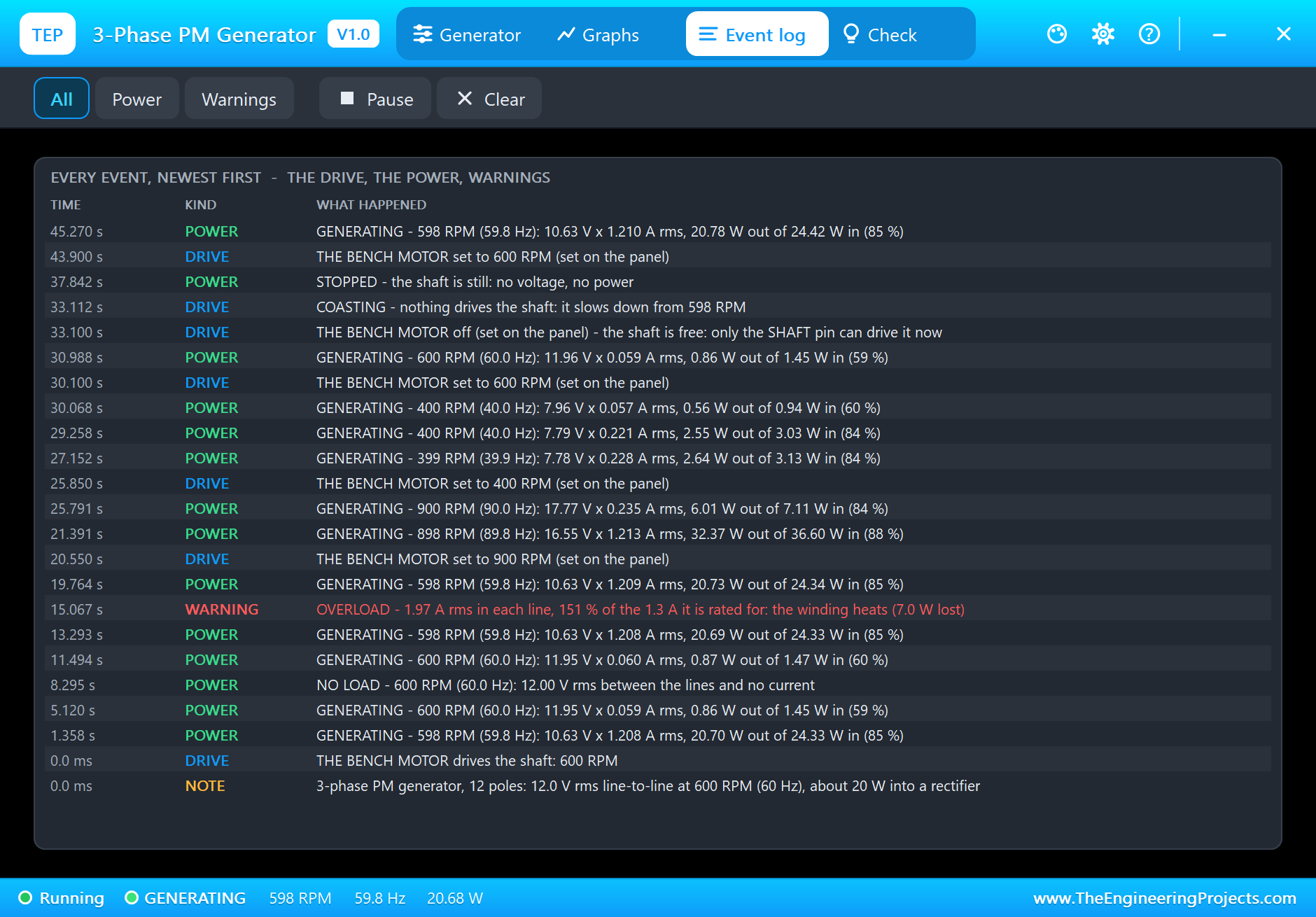
The Event log keeps every steady state with its speed, frequency, volts, amps and power, every change of the drive, and the warnings. Filter it to Power or Warnings, pause it, or clear it. More warnings you may meet: SHORT CIRCUIT when the phases or the DC side are shorted, OVERSPEED above 1500 RPM, and HOT when the winding passes 110 C.
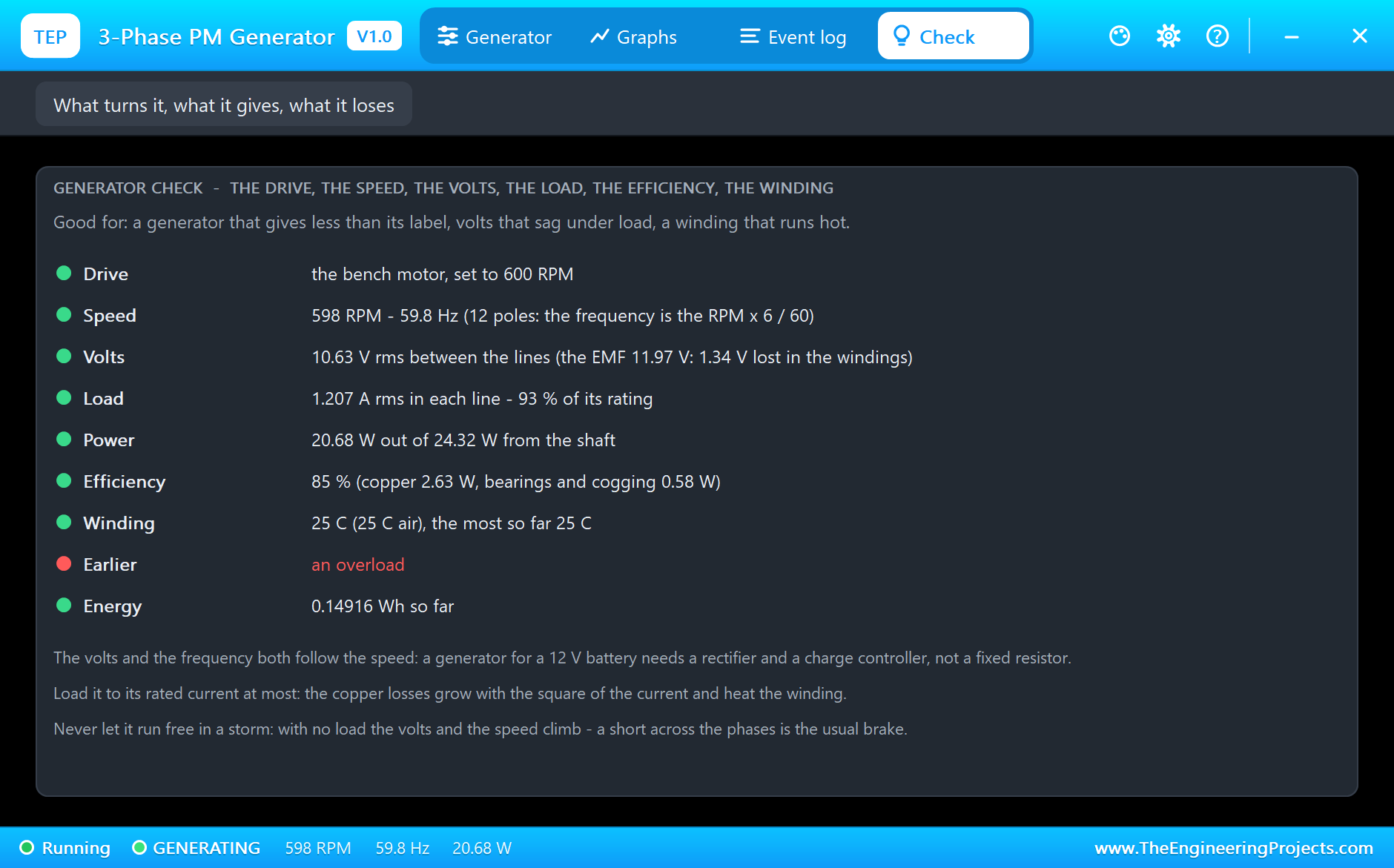
At the end of the run the Check page sums it up: "1.207 A rms in each line - 93 % of its rating", "20.68 W out of 24.32 W from the shaft" and "85 % (copper 2.63 W, bearings and cogging 0.58 W)". It also remembers the overload from earlier, so a problem that came and went is not forgotten.
How the Model Works
The three phases are in star, each with a sinusoidal EMF proportional to the speed, its resistance and its inductance. At every Newton step of the simulation the model puts them into the circuit as the equivalent delta - three R-L branches with the line-to-line EMFs - so they work with any load you connect: the rectifier board here, resistors, a motor drive or a battery charger.
The torque is the power the EMFs give, divided by the speed, and the model writes it onto the SHAFT net together with the rotor's inertia and its friction. The windings, the shaft and the load are solved together, and the analog step is held to 40 points per electrical cycle. The copper losses warm the winding over minutes, and its resistance rises with it.
We checked the models on a PC with 11 automatic tests that solve the generator, the rectifier board and the DC load together, the way SPICE does: 12.00 V rms between the lines at 600 RPM and 60 Hz; 19.31 W DC at 12.88 V into 1.5 A, 79 % of the shaft power; 24.68 V open-circuit at 900 RPM, under the INA219's 26 V; a short at 600 RPM limited to 9.00 A by the windings, with a braking torque of 1.991 N.m; and a turbine-like torque on the SHAFT pin that settles at 670 RPM with 15.52 W. The pop-up has 5 more checks, and the demo project is read back from disk with 96 checks.
Troubleshooting
- STOPPED: nothing turns the shaft - set DRIVE to BENCH with a speed, or wire a turbine to the SHAFT pin.
- NO LOAD: nothing takes the power - check the rectifier and the load.
- OVERLOAD: more than 1.6 A rms in each line - lighten the load before the winding heats.
- SHORT CIRCUIT: the phases or the DC side are shorted - the windings take all the power and brake the shaft.
- OVERSPEED: over 1500 RPM - load it or brake it.
- The parts are not simulated:
TEPPMGEN.DLLis missing from MODELS and from the project folder. - No INA219 or no load: install our INA219 library (
TEPINA219.LIBandTEPINA219.DLL). - No speed on the monitor: phase U does not reach D2 - check the U labels and R1.
- No pop-up: click OPEN PANEL on the generator's body, or turn "Open the panel at Run" on in its Settings.
Things to Know Before Wiring a Real Generator
- Know its poles: the RPM from the frequency needs the pole pairs - read the label, or count the cycles in one turn by hand.
- Rectify, then control: a battery needs a rectifier and a charge controller made for wind or water, one with a dump load - never the generator straight on the battery.
- Never let it run free in a storm: with no load the speed and the voltage climb; a switch that shorts the three phases is the usual brake.
- Rate the parts: the diodes for the short-circuit current, the capacitor for the open-circuit voltage at the highest speed.
- Protect the Arduino: a 100k resistor into an interrupt pin works because of the pin's clamp diodes; an optocoupler isolates it fully.
Limitations of the Simulation
- Not modelled: the ripple of the cogging torque (a smooth friction here), the iron losses, the magnets' temperature, armature reaction and saturation, and trapezoidal EMFs (some generators are built that way).
- The value line, the OUT LED and the OPEN PANEL button are TEP additions.
- The models are our own, fitted to the typical data of small 12 V permanent-magnet generators and SS34-type Schottky diodes; this library is not made or endorsed by any generator maker, Arduino or Labcenter.
- Licences: the demo HEX contains the Arduino AVR core 1.8.6 (LGPL) with its Wire library; the sketch is included and the README gives the source link. The INA219 and the DC load of the demo are our separate library.
- Tested in Proteus 8.5 in October 2026 with the demo as shipped: the rated point, a light load, no load, an overload, 900 and 400 RPM, coasting to a stop, and all four pages of the pop-up. Proteus 7 is not supported.
So, that was all about the 3-Phase PM Generator Library for Proteus V1.0. Next in the series, the vertical-axis wind turbine will drive this generator through its SHAFT pin. If you have any questions, ask in the comments and I will help you out. Till the next tutorial, take care and have fun!

Comments
0