


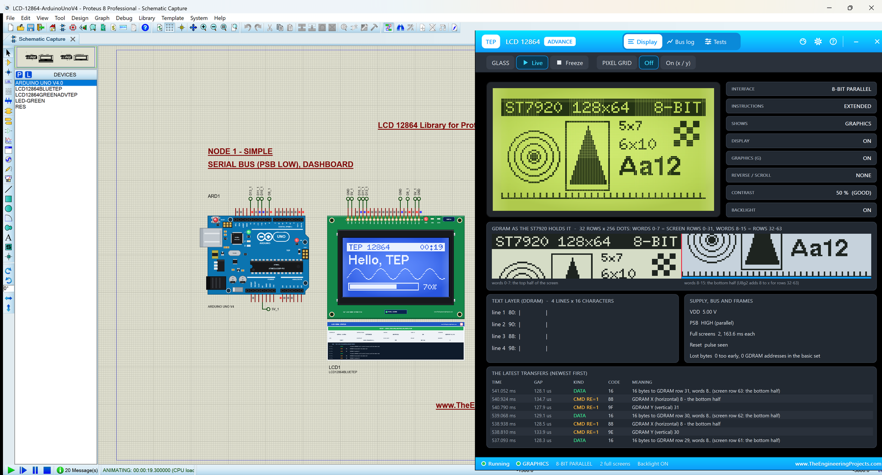
LCD 128x64 Library for Proteus V1.0 (ST7920 128x64 + Arduino)


Hello friends, I hope you all are doing great. Today, I am going to share the new LCD 12864 Library for Proteus V1.0. The 12864 is the big graphic LCD of the Arduino world: 128 x 64 dots on a 93 x 70 mm board, white dots on a blue glass or dark dots on a yellow-green one, with the ST7920 controller behind it. It is the screen of many 3D printer controllers, and the natural next step when a 16 x 2 character LCD is too small for your menus, graphs and icons. With this LCD 12864 Library for Proteus, your sketch draws on a 12864 that behaves like the real one, including its famous puzzles: the PSB pin, the G bit and the folded memory.
This is our own model of the module, with the ST7920 written from its datasheet: the serial bus and the 8-bit / 4-bit parallel bus, both instruction sets, the graphics memory, the text layer with the chip's own font, the busy times, the contrast trimmer and the backlight. You get four devices, the blue and the yellow-green module, each as LCD 12864 Simple with a live STATUS panel on the schematic and as LCD 12864 Advance with a pop-up window, a bus log and four LCD test tools. The demo runs on our Arduino UNO V4.0, with its serial monitor built into the board.
NOTICE: This library is very special to our team. The ST7920 looks simple, 128 x 64 dots, but inside it is a 256 x 32 chip folded in two, with two buses, two instruction sets and two layers on one glass. We modelled it from the datasheet, tested it dot by dot against the real U8g2 library on both buses, and made the model tell you what went wrong: PSB on the wrong level, the graphics switched off, a byte sent while the chip was busy. On the way we even found a bug in Proteus itself, and the model now explains it too. It took our team a lot of hard work and many test runs. Your feedback is the fuel that keeps us going, so please tell us what you think in the comments below or in the LCD Library board of our forum. And if our free libraries help you, you can buy us a coffee. So, let's get started with the LCD 12864 Library for Proteus V1.0:
What is a 12864 Graphic LCD (ST7920)?
The name says it: 128 x 64 dots. A 12864 is a monochrome STN LCD with an LED backlight, and the most common kind carries the ST7920 controller from Sitronix. The ST7920 keeps the picture in its own memory and refreshes the glass from it, so your Arduino only sends instructions and data. It has a special talent: besides graphics, it holds a font of its own, so it can show four lines of text without any font in your sketch. Its ROM even has 8,192 Chinese characters, which is why the module is so popular in China.
Two kinds of 12864: the name is also used for modules with the KS0108 controller, which have two chip-select pins (CS1, CS2) and no serial bus. This library is the ST7920 module: look for a PSB pin (pin 15) on the header.
The 12864 at a Glance
| LCD 12864 (ST7920) | |
|---|---|
| Glass | 128 x 64 dots, STN: white dots on blue, or dark dots on yellow-green, LED backlight |
| Controller | ST7920 (Sitronix) with an ST7921 segment driver: a 256 x 32 chip folded into 128 x 64 |
| Memory | GDRAM 64 x 256 bits (graphics), DDRAM 64 words (text), CGRAM 4 characters of your own |
| Fonts in the chip | 126 characters of 8 x 16 dots (ASCII), 8,192 Chinese characters of 16 x 16 |
| Interface | PSB high: 8-bit or 4-bit parallel; PSB low: 3-wire serial (up to 2.5 MHz at 5 V) |
| Supply | 5 V on VDD (the chip itself runs from 2.7 V; most modules are 5 V parts) |
| Board | 93 x 70 mm, 20-pin header, a contrast trimmer on the back |
Terms You Will See in This Article
| Term | Meaning |
|---|---|
| PSB | The pin that picks the bus: high (or open) = parallel, low = serial |
| GDRAM | The graphics memory: one bit per dot, in 16-bit words |
| DDRAM | The text memory: 4 lines of 16 characters in the chip's own font |
| CGRAM | Room for 4 characters of your own design, 16 x 16 dots each |
| Extended instructions | The second instruction set (RE = 1): graphics, reverse, scroll, standby |
| G bit | Graphics on or off. With G = 0 the GDRAM is kept but not shown |
| Page mode | U8g2's _1 constructors: the picture is drawn in 8 strips with a 128-byte buffer |
How the ST7920 Works
The ST7920 has two buses, and the PSB pin decides which one listens. With PSB high it is a parallel LCD like the 16 x 2: RS says instruction or data, E latches the byte on DB0 - DB7 (or two halves on DB4 - DB7). With PSB low it becomes a serial device on three of the same pins: RS turns into CS, R/W into SID (the data) and E into SCLK (the clock). Every serial transfer starts with a sync of five 1s, then the RW and RS bits, and every byte follows in two halves. The serial bus cannot read anything back.
It has two instruction sets. The basic set (RE = 0) is for text: CLEAR, HOME, the display on / off, the cursor and the DDRAM address. The extended set (RE = 1) is for graphics: the GDRAM address, REVERSE, scroll, standby and the G bit that switches the graphics layer on. The G bit has a catch: the chip takes it only when it is already in the extended set. That is why U8g2 sends 0x3E twice, and why a sketch that sends 0x36 only once from the basic set gets no graphics at all.
And it has two layers on one glass: the text from DDRAM through the font, and the graphics from GDRAM. Both show at the same time. Finally, the 128 x 64 module is really a 256 x 32 chip folded in two: the top half of the screen is GDRAM rows 0 - 31, words 0 - 7, and the bottom half is the same rows, words 8 - 15. Text works the same way, so line 3 continues line 1 in memory.
What's New in LCD 12864 Library for Proteus V1.0
- Our first ST7920 graphic LCD: the 128 x 64 module in blue and yellow-green, drawn at the real size, with the picture dot by dot on the schematic.
- Both buses: 3-wire serial and 8-bit / 4-bit parallel, picked by PSB like on the real module, with reads of the busy flag and the memory on the parallel bus.
- Both instruction sets from the datasheet, including the G bit rule, REVERSE, scroll and standby.
- Two layers: the text in the chip's own 8 x 16 font with 4 custom characters, and the graphics.
- The folded memory of the 128 x 64 module, as on a real one.
- The datasheet's waits: a byte sent within 40 ms of power-on or 1.6 ms of CLEAR is ignored and flagged.
- A contrast trimmer as a property, and the backlight on BLA / BLK with PWM.
- Four LCD test tools on the Advance device: Init check, Bus, Speed and Pixels.
- A demo on our Arduino UNO V4.0, one sketch for both buses, with the serial monitor built into the board.
- A compact package: about 1.29 MB, without the C++ source code.
LCD 12864 Simple vs LCD 12864 Advance
| LCD 12864 Simple | LCD 12864 Advance | |
|---|---|---|
| Blue device | LCD12864BLUETEP | LCD12864BLUEADVTEP |
| Yellow-green device | LCD12864GREENTEP | LCD12864GREENADVTEP |
| On the schematic | The board + the LCD 12864 STATUS panel | The board only |
| Status | Banner, 10 readouts, the last 6 transfers | A pop-up window: Display, Bus log, Tests |
| Test tools | - | Init check, Bus, Speed, Pixels |
| Best for | Seeing the state at a glance | Finding out why a screen is wrong |
Download LCD 12864 Library for Proteus
Click the button below to download LCD-12864-Library-for-Proteus-v1.0.zip (about 1.29 MB, without the C++ source code):
LCD 12864 Library for Proteus V1.0- README.txt: a detailed guide to the devices, the installation, the demo, the wiring, the test tools, the properties and real hardware.
- Proteus Library Files:
TEPLCD12864.LIB(the four devices) andArduinoV4TEP.LIBfrom our Arduino Library for Proteus V4.0, with the Arduino UNO V4.0 of the demo. - Proteus Model Files:
TEPLCD12864.DLLandTEPARDUINO.DLL. - Proteus Simulation:
LCD-12864-ArduinoUnoV4.pdsprj,LCD_12864_Demo.hex(both UNOs run it) and copies of both DLLs. - Arduino Code:
LCD_12864_Demo.ino, the demo sketch. It needs "U8g2" from the Library Manager.
No Proteus yet? Read How to Download and Install Proteus 7 and 8. New to libraries? Follow How to Install a New Library in Proteus.
How to Install LCD 12864 Library for Proteus
- Close Proteus and extract the whole zip file to a normal folder, for example your Desktop.
- Copy the two files from Proteus Library Files into the LIBRARY folder, usually
C:\Program Files (x86)\Labcenter Electronics\Proteus 8 Professional\LIBRARY(on some PCsC:\ProgramData\Labcenter Electronics\Proteus 8 Professional\LIBRARY). - Copy
TEPLCD12864.DLLandTEPARDUINO.DLLfrom Proteus Model Files into the MODELS folder. If you have our Arduino Library V4.0, its files are the same. - Delete
TEPLCD12864.IDXfrom the LIBRARY folder if there is one. - Start Proteus, press P and search for 12864: you get the four devices.
Tip: the demo project needs its .hex file and the two DLLs beside it, so keep the Proteus Simulation folder together. The library was tested in Proteus 8.5; Proteus 7 is not supported.
The 12864 Board in Proteus
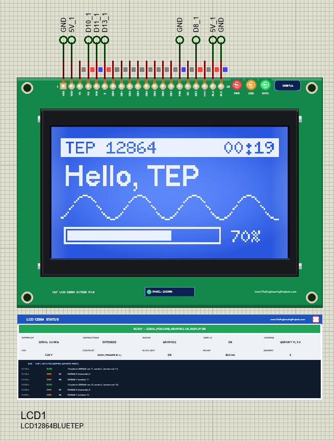
The part looks like the real module: the green board with its four holes, the glass in its black bezel and the 20-pin header on top, drawn at the real size. When the simulation runs, the glass shows the picture dot by dot: white dots on the blue glass, dark dots on the yellow-green one.
Pinout
| Pin | Name | Function |
|---|---|---|
| 1, 2 | VSS, VDD | Ground and 5 V |
| 3 | V0 | The contrast voltage (the module's trimmer sets it) |
| 4 | RS | Parallel: instruction / data. Serial: CS (chip select, active high) |
| 5 | R/W | Parallel: read / write. Serial: SID (the data) |
| 6 | E | Parallel: enable. Serial: SCLK (the clock) |
| 7 - 14 | DB0 - DB7 | The parallel data bus (4-bit mode uses DB4 - DB7) |
| 15 | PSB | High or open = parallel, low = serial |
| 16 | NC | Not connected |
| 17 | RST | Reset, active low (the module pulls it up) |
| 18 | VOUT | The LCD voltage output (for an external contrast potentiometer) |
| 19, 20 | BLA, BLK | The backlight: anode to 5 V, cathode to GND |
LEDs and the Properties
A PWR LED lights with power, CMD flashes with an instruction and DATA with a data byte. A TEP strip under the glass holds the SIMPLE / ADVANCE badge and the panel button. The LEDs, the strip and the panels are TEP additions; a real module has none of them.
| Property | Values | What it does |
|---|---|---|
| PANEL | OPEN (default), CLOSED | Simple only: the STATUS panel at the start |
| CONTRAST | 0 - 100 % (default 50) | The module's contrast trimmer: 35 - 70 % is good, lower is faint, higher turns the background grey |
Two Layers: The ST7920's Own Font
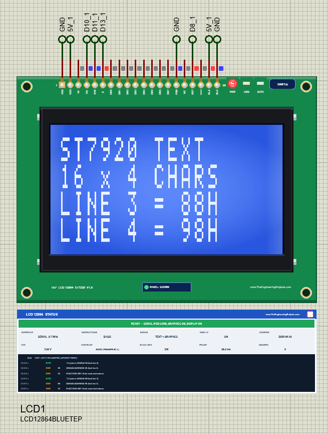
U8g2 draws everything as graphics, with its own fonts. But the ST7920 can also show text by itself: write character codes to the DDRAM and the chip draws them from its ROM, 16 characters on each of 4 lines. The demo's ROM command does exactly that with a few raw instructions. Note the addresses: the lines are 80, 90, 88 and 98, not 80, 90, A0, B0, because line 3 is the right half of line 1 in the folded memory. The model also keeps the 4 CGRAM characters of your own design.
Text and graphics show together. That is handy for a fixed title over a graph, and a classic surprise when old text stays on the glass under a new picture: clear the layer you do not use.
The G Bit: Why the Graphics Do Not Show
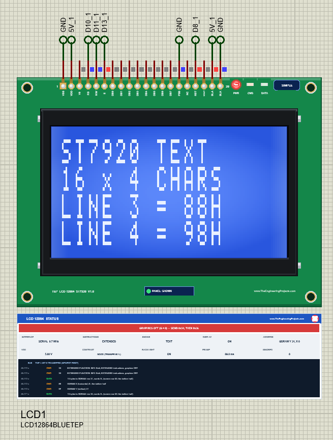
"I write to the GDRAM and nothing shows" is the most common ST7920 question. The answer is usually the G bit: it was never set, or set from the basic set, where the chip ignores it. The model shows exactly that: the GDRAM keeps the picture, the glass shows only the text layer, the banner turns red, and the simulation log says once what to send. GRAPHICS ON brings the picture back at once.
REVERSE and Standby
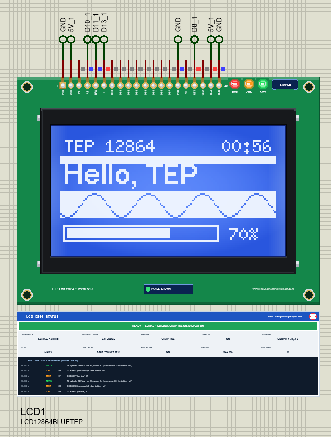
REVERSE inverts one text line (16 rows of dots). Here the fold shows again: the chip's line 1 is the module's lines 1 and 3, so REVERSE 1 inverts both, exactly as on a real 12864. Sending it again switches it off.
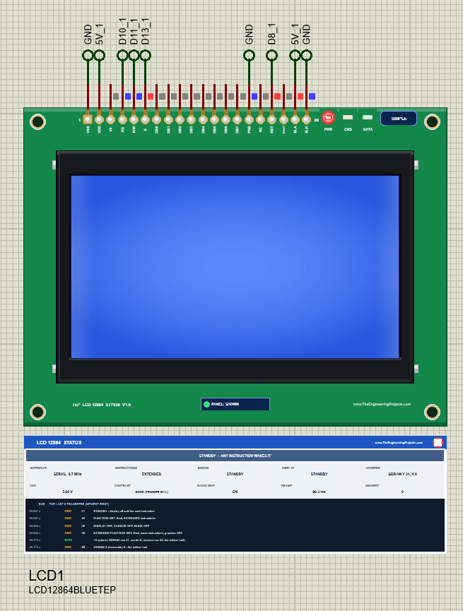
In standby the chip stops driving the glass but keeps its memory; the next instruction wakes it. WAKE brings the dashboard back without a redraw.
LCD 12864 Simple: The STATUS Panel
The Simple device keeps a live LCD 12864 STATUS panel right under the board. The banner says READY with the bus, or what is wrong: NO POWER, WAITING (with a hint when PSB is open), STUCK, GDRAM ADDRESS IN THE BASIC SET, BYTES LOST, GRAPHICS OFF, STANDBY, DISPLAY OFF, CONTRAST or BACKLIGHT OFF. Ten readouts show INTERFACE (with the serial clock), INSTRUCTIONS, SHOWS, DISPLAY, ADDRESS, VDD, CONTRAST, BACKLIGHT, FRAME (the time of a full screen) and IGNORED, and the dark log lists the last 6 transfers. The red X closes the panel; PANEL on the strip opens it again.
LCD 12864 Advance: The Pop-Up Window
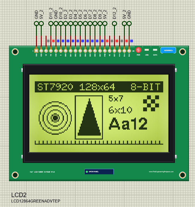
The Advance device keeps only the board on the schematic and opens a TEP pop-up window at Run, with the look of our serial monitor: the tabs Display, Bus log and Tests, Settings, Help and a theme switch.
The Display Page
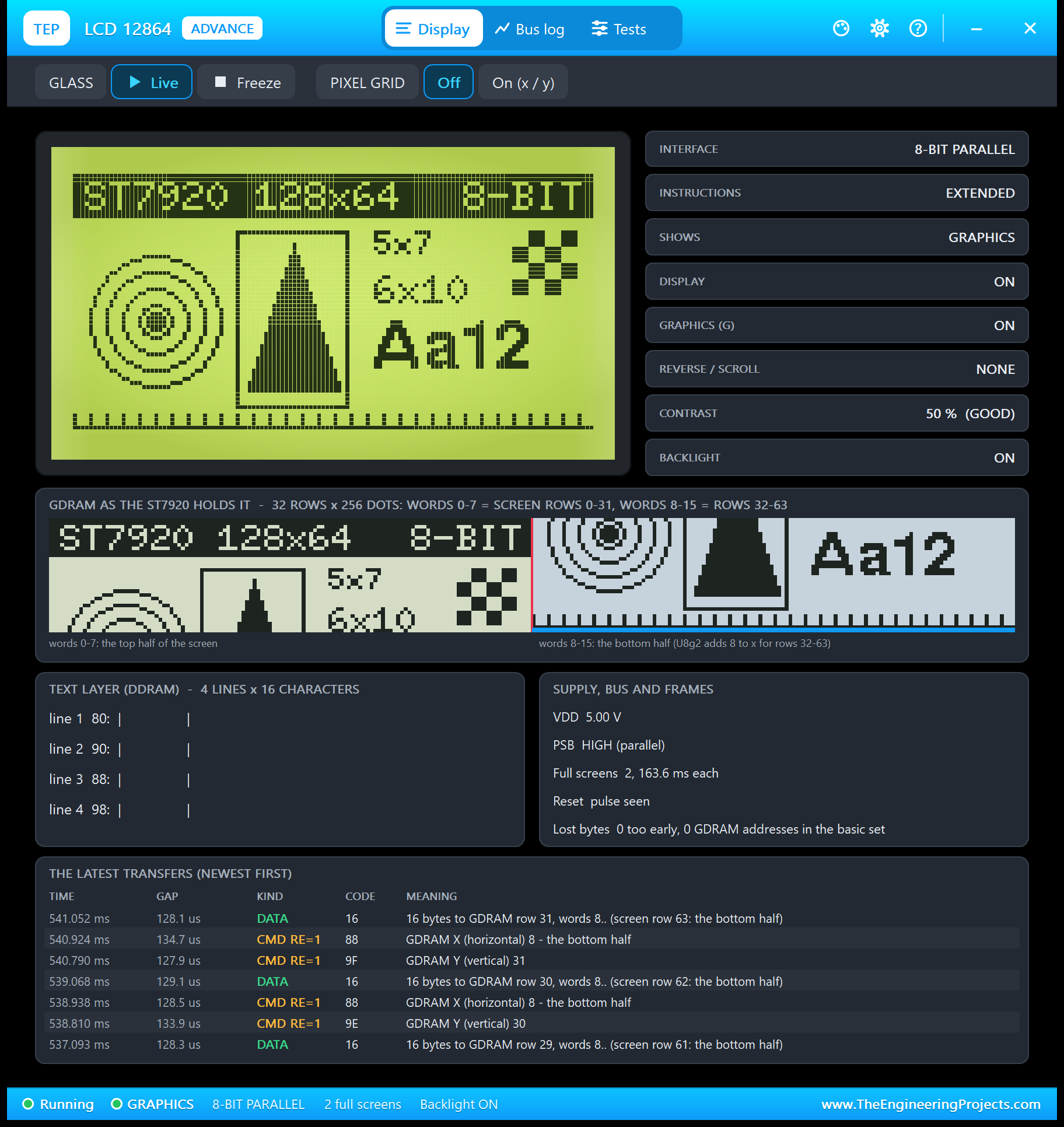
The GDRAM card is the best picture of the fold you will find: the left half is the top of the screen, the right half (words 8 - 15) is the bottom. The tiles read the controller: interface, instruction set, what shows, display, G, reverse / scroll, contrast and backlight. Freeze holds the picture; the pixel grid adds x / y numbers.
The Bus Log Page
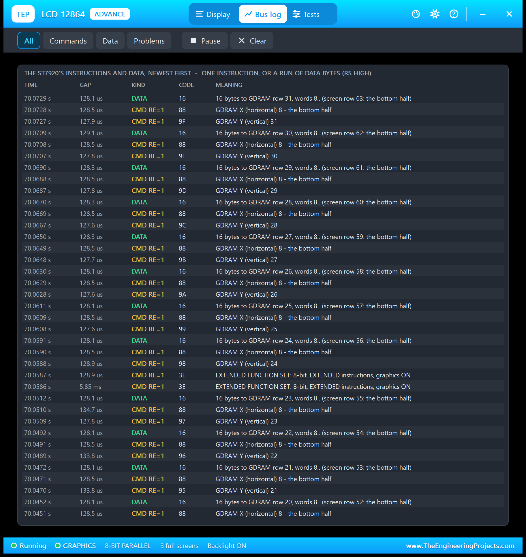
Every instruction and every run of data, newest first: the time, the gap, the kind, the code and what it means. The filters show Commands, Data or only Problems.
The Tests Page: Four LCD Test Tools
1. Init Check: Did the Start-Up Follow the Datasheet?
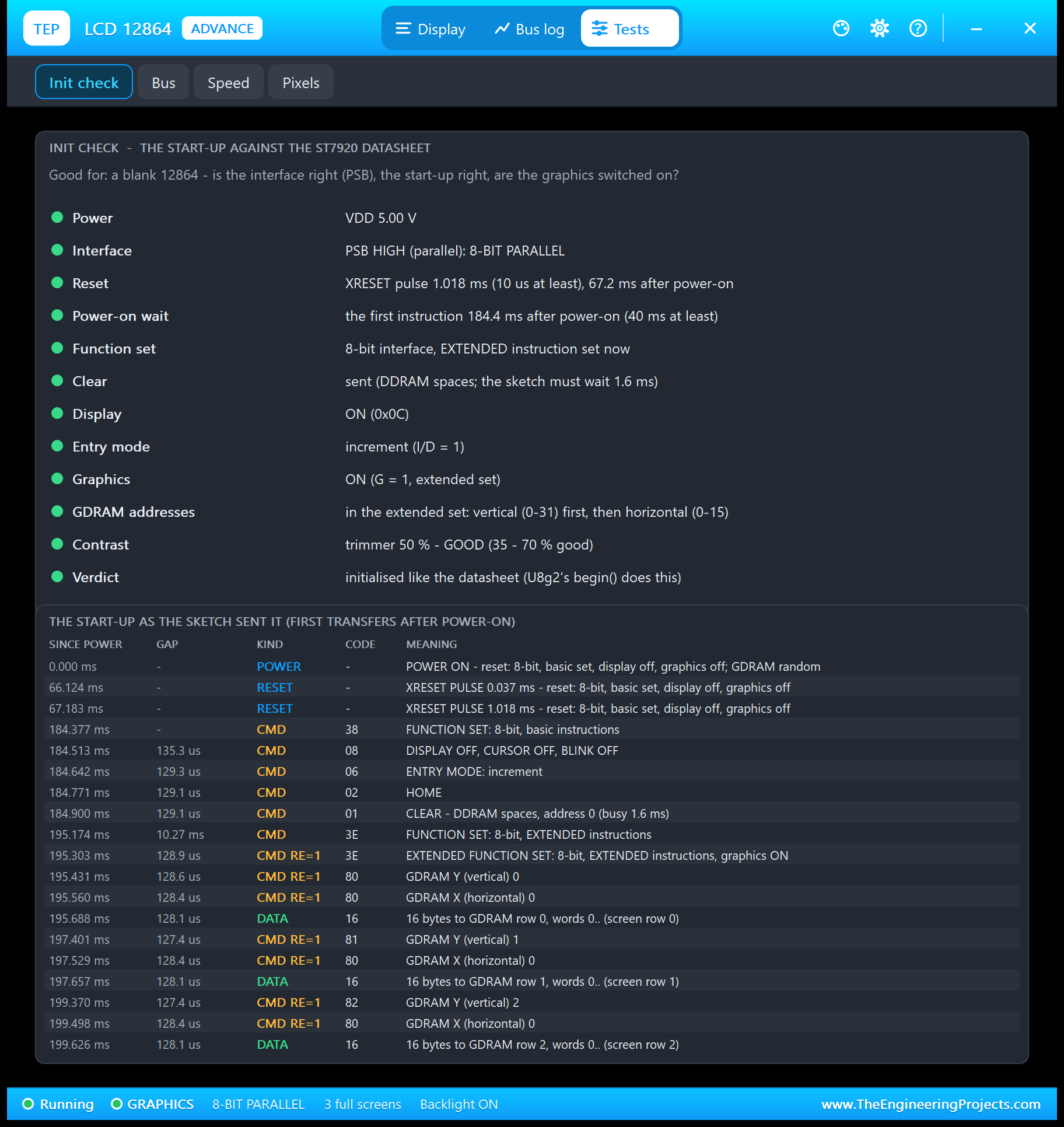
Good for a blank 12864: the supply, PSB and the bus it picks, the reset pulse, the 40 ms power-on wait, FUNCTION SET, CLEAR, DISPLAY, the entry mode, the G bit, where the GDRAM addresses were sent, the contrast and a verdict. Below it, the start-up as the sketch really sent it: here U8g2's 38 08 06 02 01, then 3E 3E and the first rows.
2. Bus: Is the Sketch Talking to This LCD?
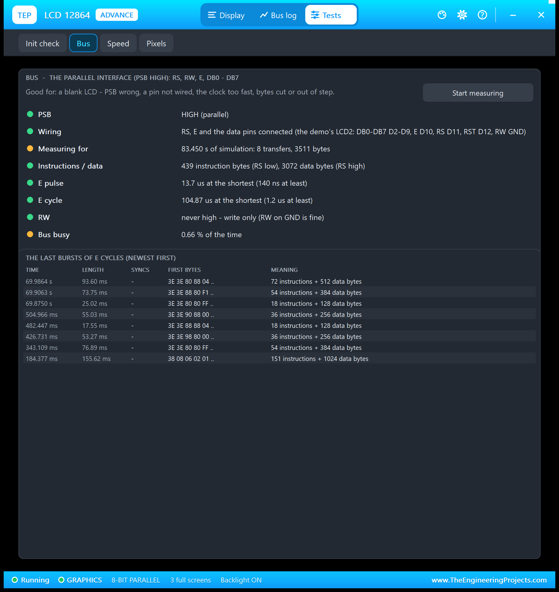
Good for a blank LCD: PSB, the pins connected, the bytes and the timing against the datasheet. On the serial bus it also shows the clock (the ST7920 takes up to 2.5 MHz at 5 V), the syncs, half-bytes out of step, cut bytes, and a stuck transfer, which brings us to a Proteus surprise.
A Proteus 8.5 Surprise: Hardware SPI in Mode 3
U8g2 drives the ST7920 in SPI mode 3, with the clock idling high. In our first runs the serial node stopped in begin(): CS went high and not a single clock followed. A small probe sketch proved the cause: Proteus 8.5's ATmega328P model never clocks its hardware SPI in modes 2 and 3. A real Arduino is fine. So the demo uses U8g2's software SPI on the same pins, and the model now spots the symptom and tells you the fix on its banner: STUCK - CS HIGH, NO CLOCK: IN PROTEUS USE U8G2 SW_SPI.
3. Speed: How Fast Can the Picture Change?
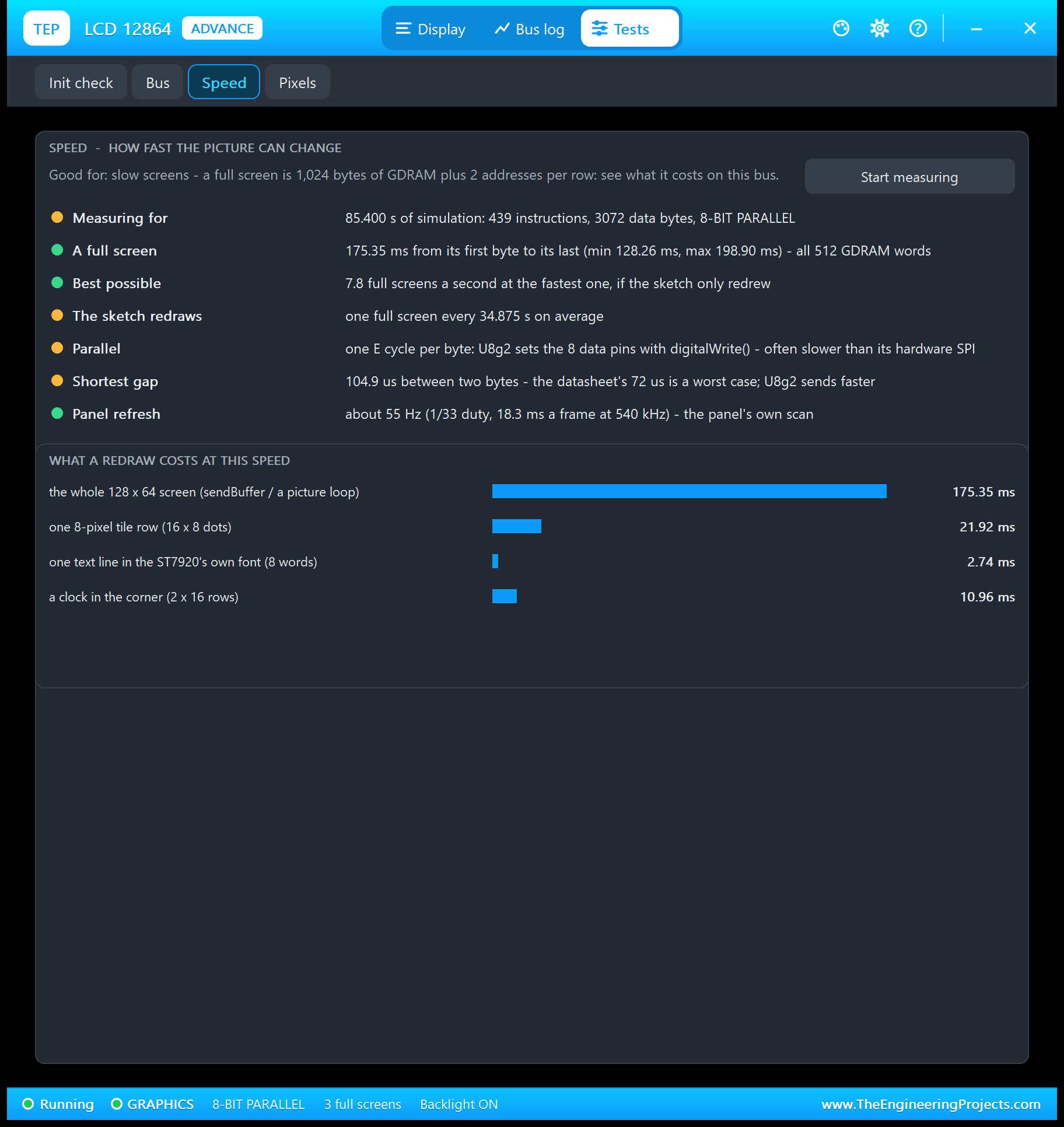
A full screen is 1,024 bytes of GDRAM plus two addresses for each of its 64 rows. The fastest one here is U8g2's clear in begin(); a picture loop takes longer because U8g2 draws the next strip between the rows it sends. The text layer is cheap: a line in the chip's own font costs 16 bytes, about 2.7 ms here.
4. Pixels: Where Does a Dot Live?
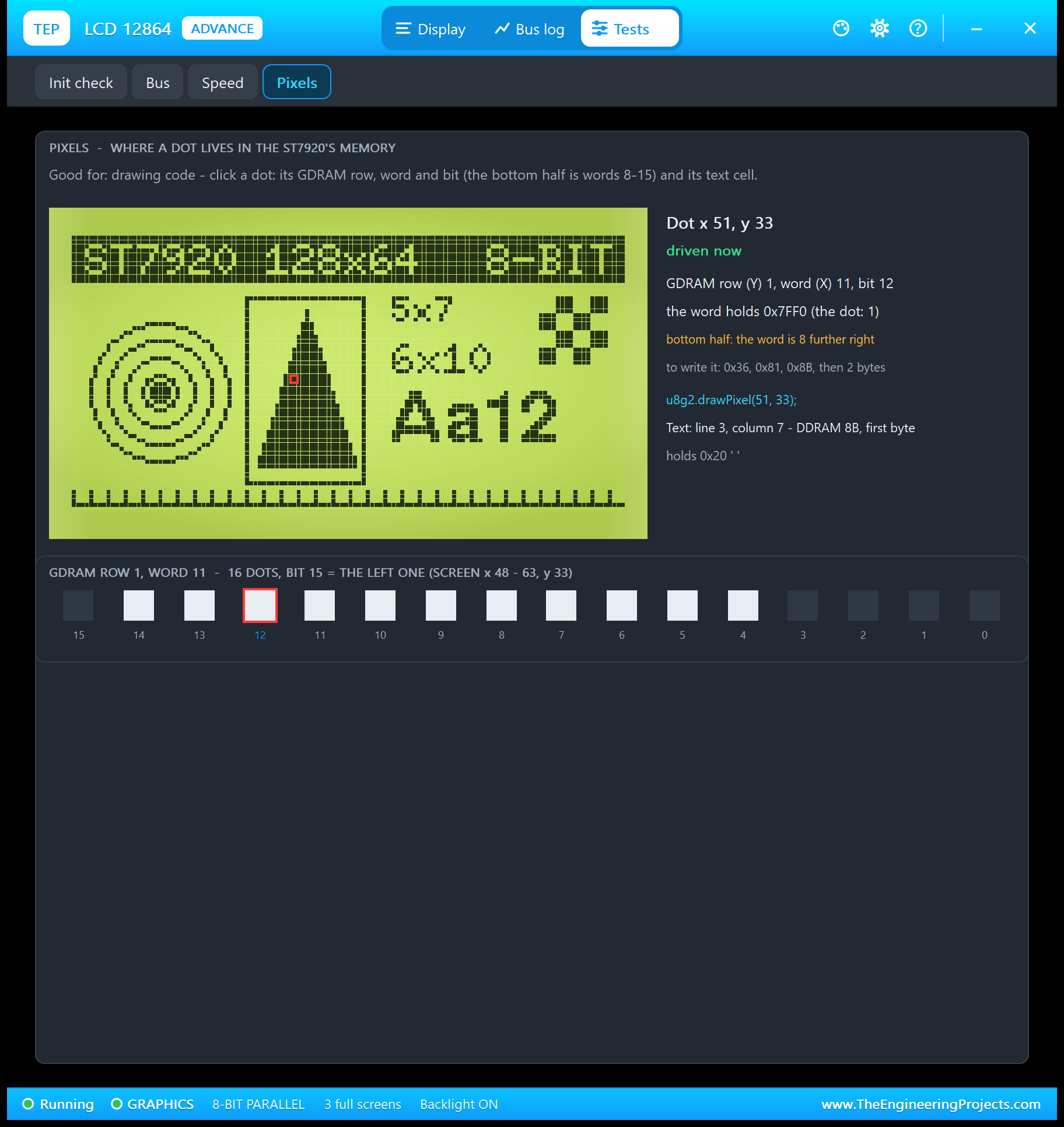
Click a dot and the tool shows the fold in numbers: its GDRAM row, word and bit, the word's value, the instructions that write it, the u8g2.drawPixel() line, its text cell, and the 16 dots of that word, magnified. If you write your own driver, this is the page to keep open.
12864 LCD with Arduino in Proteus
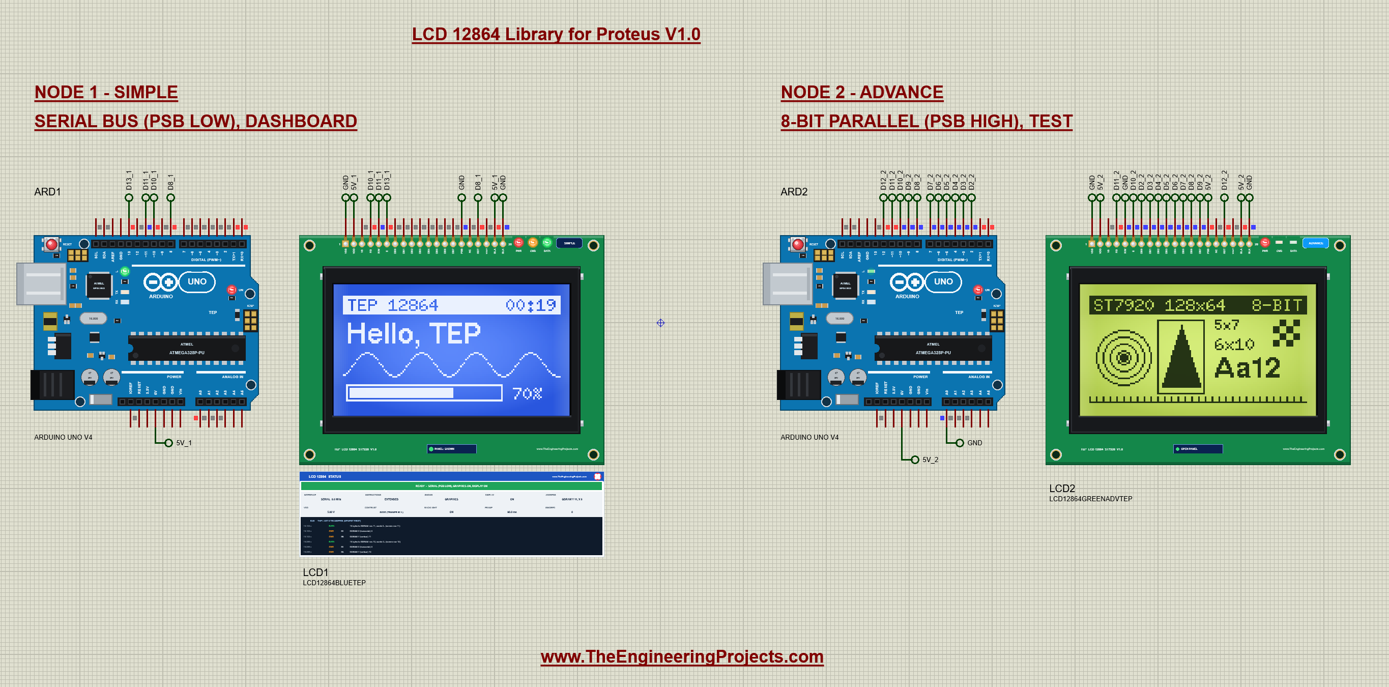
Open LCD-12864-ArduinoUnoV4.pdsprj. Two Arduino UNO V4.0 boards from our Arduino UNO Library for Proteus V4.0 run the same sketch; ARD2's A0 is tied to GND, so it uses the parallel bus and starts with the graphics test. Each UNO has the serial monitor built in, so there is no Virtual Terminal to wire (see our Introduction to Arduino UNO for its pins).
Wiring: Serial (PSB Low)
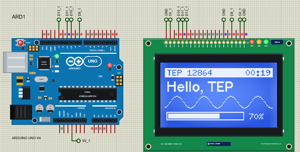
| LCD pin | Arduino UNO |
|---|---|
| VSS | GND |
| VDD | 5V |
| RS (CS) | D10 |
| R/W (SID) | D11 (MOSI) |
| E (SCLK) | D13 (SCK) |
| PSB | GND |
| RST | D8 |
| BLA | 5V |
| BLK | GND |
Wiring: 8-Bit Parallel (PSB High)

| LCD pin | Arduino UNO |
|---|---|
| DB0 - DB7 | D2 - D9 |
| E | D10 |
| RS | D11 |
| RST | D12 |
| R/W | GND (write only) |
| PSB | 5V |
| VSS / VDD / BLA / BLK | GND / 5V / 5V / GND |
The Arduino Code
The demo uses the U8g2 library (version 2.36.19) in page mode, with one constructor for each bus:
U8G2_ST7920_128X64_1_SW_SPI lcdSerial(U8G2_R0, /* clock=*/ 13, /* data=*/ 11, /* CS=*/ 10, /* reset=*/ 8);
U8G2_ST7920_128X64_1_6800 lcdParallel(U8G2_R0, 2, 3, 4, 5, 6, 7, 8, 9, /* enable=*/ 10, /* cs=*/ U8X8_PIN_NONE, /* dc=*/ 11, /* reset=*/ 12);
In setup(), A0 picks the bus, so one HEX file runs both nodes; then begin() starts the LCD:
  pinMode(BUS_PIN, INPUT_PULLUP);
  parallel = digitalRead(BUS_PIN) == LOW;
  if (parallel) { lcd = &lcdParallel; screen = TEST; }
Every picture is a U8g2 picture loop: show() calls firstPage(), then this drawing code once for each of the 8 strips until nextPage() says the screen is done, so only 128 bytes of RAM hold a strip:
void draw(U8G2& g) {
  if (screen == DASH) drawDash(g);
  else if (screen == TEST) drawTest(g);
}
U8g2 sends 0x3E twice at the start of every strip, which switches the graphics on; so after a picture with GRAPHICS OFF, show() switches them off again.
The ROM command writes into the text layer with raw instructions through U8g2's u8x8_cad functions. Note the line addresses of the folded memory:
static const byte ADDR[4] = {0x80, 0x90, 0x88, 0x98}; u8x8_cad_StartTransfer(x);
u8x8_cad_SendCmd(x, 0x30); // basic instruction set (8-bit)
u8x8_cad_SendCmd(x, ADDR[line]); // the DDRAM address of the line
u8x8_cad_SendData(x, 16, (uint8_t*)b); // 16 half-width characters = 8 addresses
u8x8_cad_EndTransfer(x);GRAPHICS ON / OFF shows the G bit rule: the first 0x34 enters the extended set, the second byte sets G:
  u8x8_cad_SendCmd(x, 0x34);                     // the extended set (from the basic set this only sets RE)
  u8x8_cad_SendCmd(x, graphicsOff ? 0x34 : 0x36);
And REVERSE is one extended instruction, 04 plus the line:
u8x8_cad_SendCmd(x, 0x04 | line); // REVERSE line 0..3SPEED times a full picture loop with millis(), so you can compare it with the Speed tool:
    const unsigned long t0 = millis();
    show();
    frameMs = millis() - t0;
The dashboard redraws only twice a second, for its clock and the moving wave:
if (screen == DASH && !sleeping && millis() - lastDraw >= 500) { // twice a second: the clock and the waveTo change the sketch, export a new HEX file and load it into the UNO; see How to get the HEX file from Arduino. New to Arduino? Start with our Arduino Tutorial for Beginners.
Serial Monitor Commands
| Command | What it does |
|---|---|
| HELP / STATUS | The command list / the bus, screen, text, bar, graphics, sleep, ROM lines, reversed lines |
| TEXT <text> | The big text on the dashboard (16 characters) |
| BAR <0-100> | The bar at the bottom |
| DASH / TEST / CLEAR | The dashboard / the graphics test / a blank screen |
| SPEED | A timed full screen: "a full screen took N ms" |
| ROM <1-4> <text> | A line in the ST7920's own font (the text layer); ROM CLEAR clears it |
| REVERSE <1-2> | Toggles a reversed line (line 1 shows as lines 1 + 3, line 2 as 2 + 4) |
| GRAPHICS ON / OFF | The G bit: OFF = only the text layer shows |
| SLEEP / WAKE | Standby (display off) / display on |
How to Run the Demo
- Press Run. Both monitor windows and LCD2's pop-up open; move them aside. The glasses stay blank while U8g2 clears the memory, then show the dashboard and the graphics test.
- Type STATUS, TEXT Hi TEP and BAR 25 in ARD1's monitor; then CLEAR and ROM 1 HELLO, GRAPHICS OFF and GRAPHICS ON, REVERSE 1, SLEEP and WAKE.
- Close and open LCD1's panel.
- Type SPEED in ARD2's monitor and look at the Speed tool; try the other tools on LCD2's pop-up.
LCD 12864 Proteus Simulation Results
The Built-in Serial Monitor in Its Simple Interface
Each Arduino UNO V4.0 carries its own copy of our TEP Serial Monitor Advance, wired inside the board to D0 / D1 like the USB chip of a real UNO. Its window, "TEP Arduino UNO - ARD1", opens at Run, and a click on the board's USB port opens it again. The screenshots show its Simple interface: only the log and the line to send.
- Switch to it: press Ctrl+Shift+U, or use the monitor's ... menu.
- Back to the full view: press Esc; the full view has the Board, Monitor and Plotter tabs.
Read all about the monitor in TEP Serial Monitor Advance for Proteus.
ARD1: STATUS
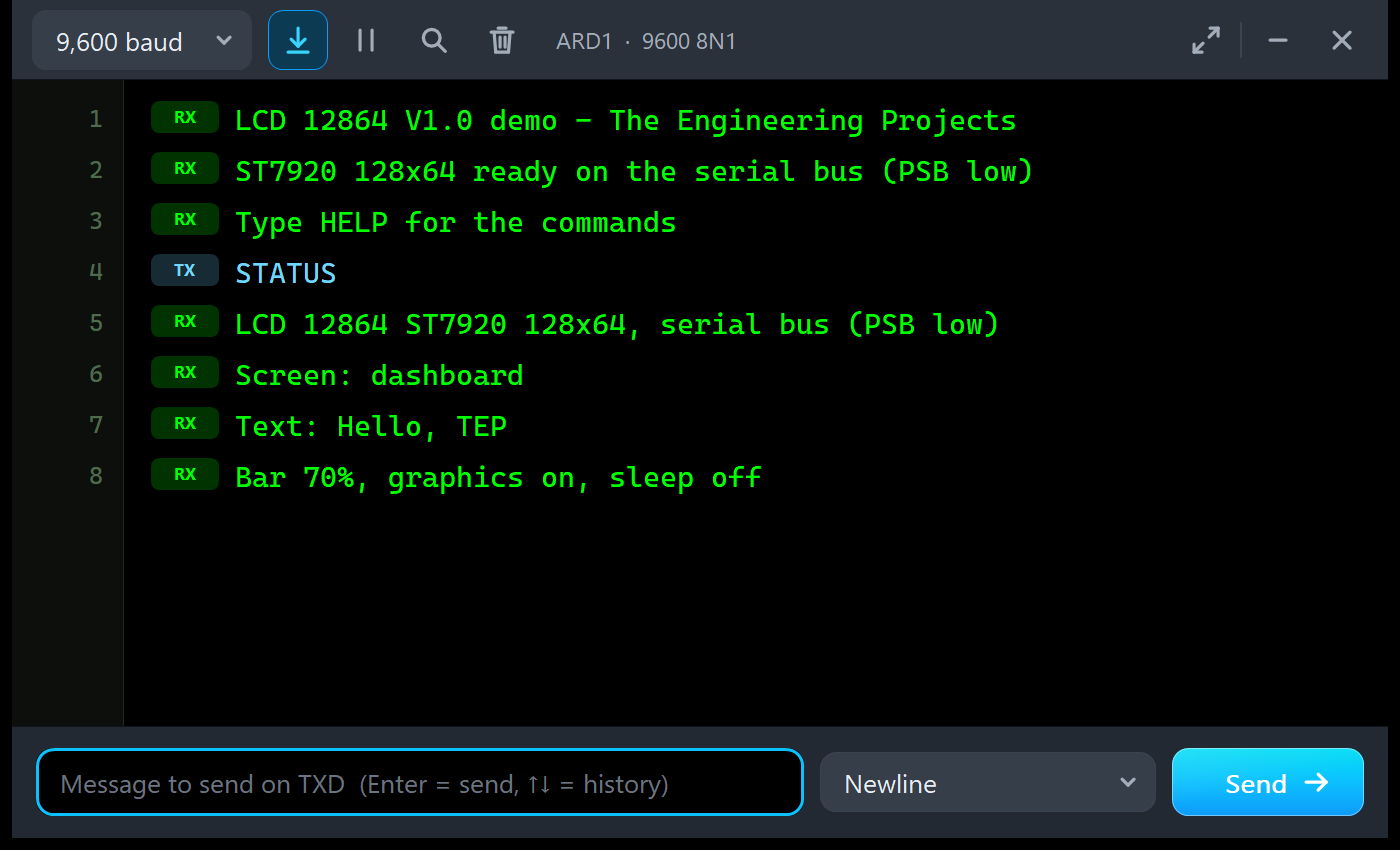
LCD 12864 V1.0 demo - The Engineering Projects
ST7920 128x64 ready on the serial bus (PSB low)
Type HELP for the commands
STATUS
LCD 12864 ST7920 128x64, serial bus (PSB low)
Screen: dashboard
Text: Hello, TEP
Bar 70%, graphics on, sleep off
ARD1: REVERSE, SLEEP and SPEED
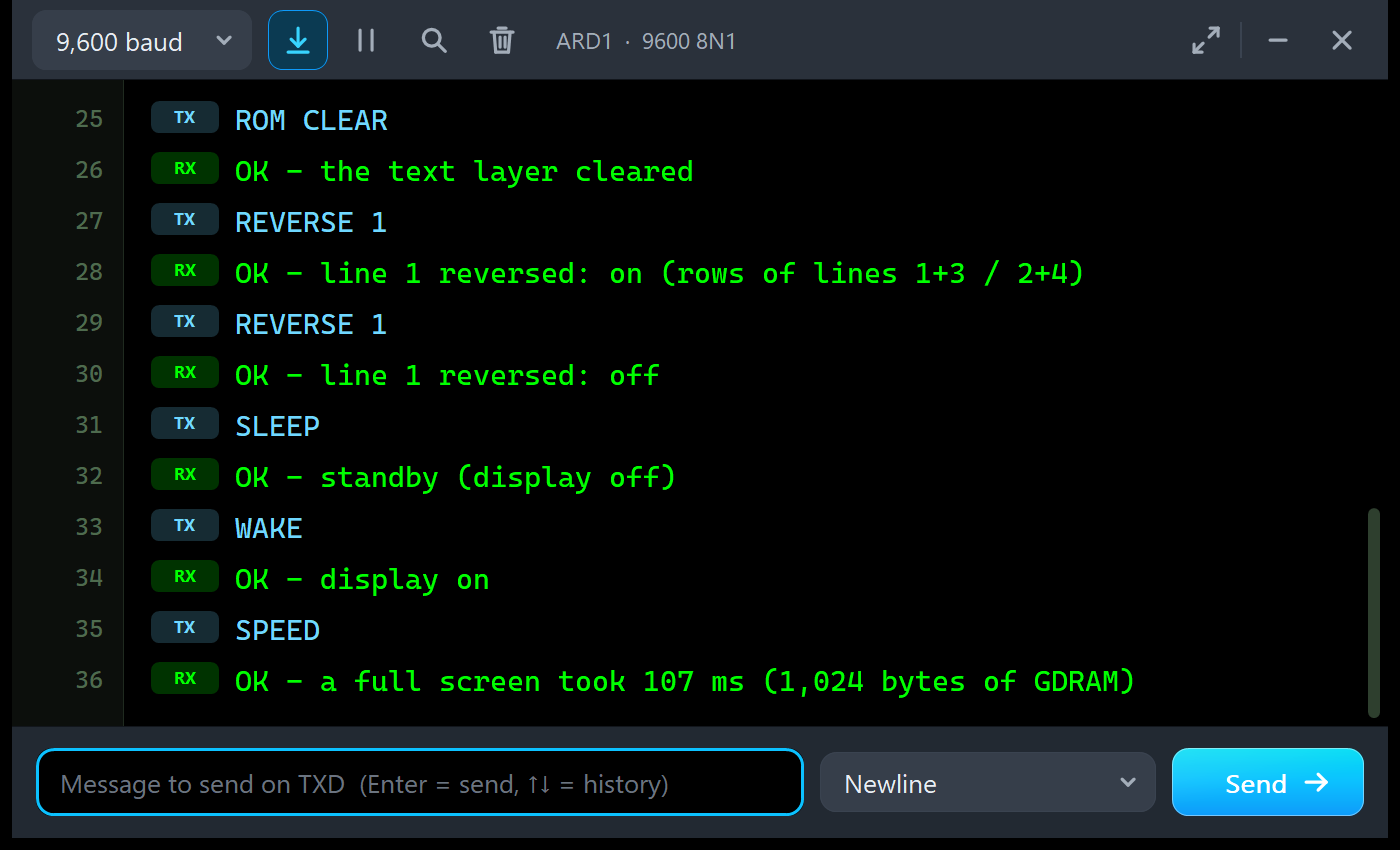
ROM CLEAR
OK - the text layer cleared
REVERSE 1
OK - line 1 reversed: on (rows of lines 1+3 / 2+4)
REVERSE 1
OK - line 1 reversed: off
SLEEP
OK - standby (display off)
WAKE
OK - display on
SPEED
OK - a full screen took 107 ms (1,024 bytes of GDRAM)
ARD2: SPEED on the Parallel Bus
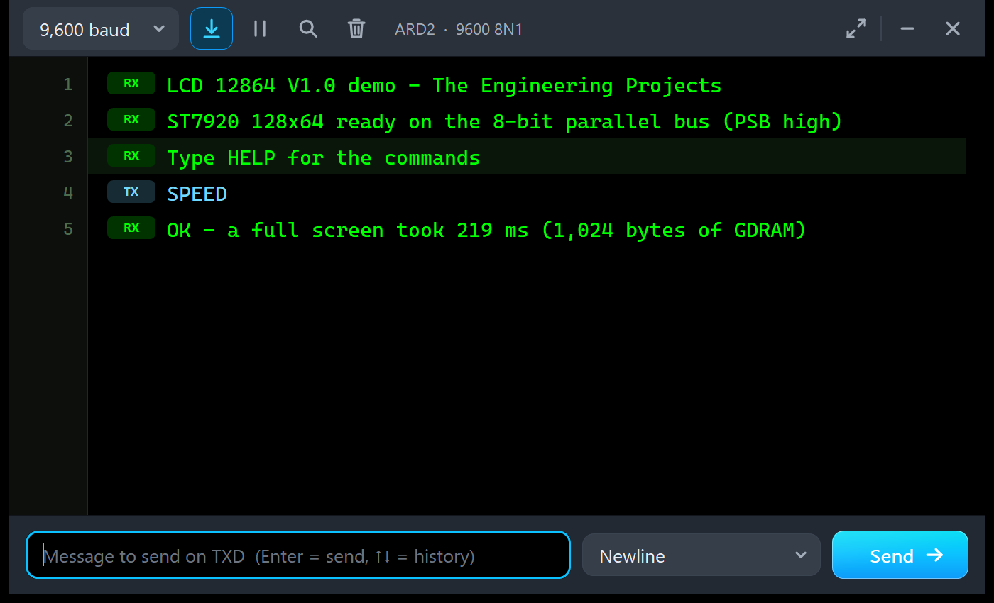
LCD 12864 V1.0 demo - The Engineering Projects
ST7920 128x64 ready on the 8-bit parallel bus (PSB high)
Type HELP for the commands
SPEED
OK - a full screen took 219 ms (1,024 bytes of GDRAM)
A surprise for many: the parallel bus is slower here, 219 ms against 107 ms. U8g2 sets the eight data pins one by one with digitalWrite(), while the serial bus shifts each bit with a single pin. The Speed tool measured the same picture loop from its first byte to its last: 198.90 ms on the bus.
Troubleshooting
- The glass stays dark and the PWR LED is off: no power. Check VDD and VSS (the module needs 5 V).
- WAITING - NOTHING ON THE BUS YET: nothing reached the LCD. Check the wiring for the bus that PSB picks; the Bus tool lists the pins that are not connected.
- WAITING - PSB OPEN = PARALLEL: the sketch talks serial, but PSB is open or high. Tie PSB to GND.
- STUCK - CS HIGH, NO CLOCK: a
_HW_SPIconstructor in Proteus 8.5. UseU8G2_ST7920_128X64_1_SW_SPIon the same pins. - GRAPHICS OFF (G = 0): the GDRAM is written but not shown. Send 0x34, then 0x36 (or 0x36 twice).
- GDRAM ADDRESS IN THE BASIC SET: the addresses went to the text layer. Switch to the extended set first.
- BYTES LOST - SENT WHILE BUSY: wait 40 ms after power-on and 1.6 ms after CLEAR.
- The bottom half of a drawing appears at the top, shifted right: rows 32 - 63 are GDRAM rows 0 - 31, words 8 - 15. U8g2 does this for you.
- Old text over a new picture: both layers show; clear the text layer with CLEAR (0x01).
- CONTRAST TOO LOW / TOO HIGH: set the CONTRAST property to 35 - 70 %.
- BACKLIGHT OFF: BLA to 5 V and BLK to GND.
- The part or the UNO is not simulated, or no monitor window: TEPLCD12864.DLL or TEPARDUINO.DLL is missing from MODELS and the project folder; a closed monitor opens again with a click on the UNO's USB port.
- The Advance pop-up does not appear: click OPEN PANEL on the strip.
Things to Know Before Using a Real 12864
The demo sketch uses only U8g2 and Serial, so it runs on a real UNO and 12864 too. Keep in mind:
- Check the controller: an ST7920 module has a PSB pin; a KS0108 module (CS1 / CS2) needs another driver.
- Hardware SPI works on real hardware:
U8G2_ST7920_128X64_1_HW_SPI lcd(U8G2_R0, 10, 8)with the same serial wiring is faster than software SPI. - PSB: on some boards it is a solder jumper on the back. Serial needs it low.
- Contrast: turn the trimmer on the back until the dots are dark and the background clear. Without a trimmer, use a 10 kohm potentiometer between VOUT and VDD with its wiper on V0.
- The backlight: most boards have its resistor on board; check yours before you wire BLA to 5 V.
- 5 V: most 12864 modules are 5 V parts; for a 3.3 V board, buy a module made for 3.3 V.
- Speed: a full screen takes about 100 - 200 ms on an UNO; redraw only when something changes.
Limitations of the Simulation
- Not modelled: the chip's Chinese font ROM (a 16 x 16 Chinese code shows as a box), the 72 us instruction time (drivers send faster and real modules take it; the tools show the gaps), V0 and VOUT (the CONTRAST property stands for the trimmer), the icon RAM, the panel's response time and flicker, timing violations shorter than the simulation's edges, the current draw, and damage from a reversed supply (the model only warns).
- The LEDs, the strip with the badge and the panel button, and the panels are TEP additions.
- The model is our own implementation, written from the ST7920 datasheet. ST7920 is a Sitronix part; this library is not made or endorsed by Sitronix, the U8g2 project or Labcenter.
- Licences: the demo sketch uses U8g2 2.36.19 (two-clause BSD licence) with its fonts 6x10 and 5x7 (public domain) and helvB12 (an X11 font by Adobe and Digital Equipment Corporation). The HEX file contains them and the Arduino AVR core 1.8.6, which includes LGPL-licensed code; its source code is on GitHub. The README holds the licence texts.
- Tested in Proteus 8.5 in October 2026 (the demo as shipped on two Arduino UNO V4.0 boards with their built-in monitors, the serial and the parallel bus, the dashboard and the graphics test, the Serial commands, the text layer, GRAPHICS OFF, REVERSE, SLEEP / WAKE, the panel, the pop-up and the four tools, and every screenshot here; about 0.6 x real time with the pop-up and both monitors open) and with automatic PC checks, 0 failed: 139 with the real demo sketch and the unmodified U8g2 talking bit by bit to the model on both buses, where the glass equals U8g2's own full-buffer picture dot by dot after every command, 64 on the controller alone, 6 on the pop-up pages, and the demo project read back from disk. Proteus 7 is not supported.
Looking for more displays? Our TFT ST7735 Library for Proteus V1.0 has the 1.8" colour TFT, our Nokia 5110 LCD Library for Proteus V1.0 the classic 84 x 48 graphic LCD, and our OLED Library for Proteus V1.0 the 0.96", 0.91" and 1.3" OLEDs in one library.
So, that was all about the LCD 12864 Library for Proteus V1.0. I hope PSB, the G bit and the folded memory of the ST7920 are clear now, so your 12864 works the first time you wire a real one. If you use the LCD 12864 Library for Proteus in a project, please share your feedback in the comments or in our forum, and if you have any questions, ask in the comments and I will help you out. Till the next tutorial, take care and have fun!
Comments
0