


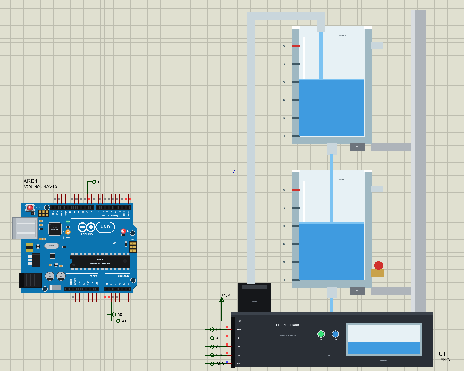
Coupled Tanks Level Control Lab Library for Proteus


Hello friends, I hope you all are doing great. Today, I am going to share the new Coupled Tanks Level Control Lab Library for Proteus, the sixth and last control plant of our University Lab series. Water tanks are where process control starts: a pump, a tank, a level to hold, and a flow out that changes with the level itself. Put a second tank under the first and you have the coupled tanks of process control labs. You can control the top tank directly, but the bottom one only through the top one. That is the classic reason for cascade control.
Coupled Tanks Level Control Lab Library for Proteus
Latest version: V1.0 (November 2026, this tutorial)
Helping Tools
- Serial Monitor Advance: a serial terminal window for the UART of your board
- Serial Monitor Expert: the serial monitor with extra debugging tools
- LCD Library for Proteus V3.0: 16x2, 20x4 and I2C LCDs to show your readings
Our library brings that lab into Proteus at true scale. It is our own design: two clear tanks one above the other on an aluminium column, a 12 V pump in the base feeding the top tank, an orifice in each tank's floor, a level sensor under each tank and a leak valve on the bottom one. The model follows Torricelli's law for every outflow, the pump's flow and its lag, and the overflows. The pop-up works out the linear model at the levels, the PI gains for the top tank and for a cascade on the bottom one. It measures every level move and the leak. The demo fills the tanks, steps the top one, switches to the cascade, steps the bottom one and rides out a leak, from an Arduino UNO.
NOTICE: Our team has put a lot of effort into these small parts: the bodies, the animation and the pop-ups are all our own design, and you get them free. Your feedback is the fuel that keeps us going, so please tell us what you think in the comments below or in the Coupled Tanks board of our forum. And if our free libraries help you, you can buy us a coffee. So, let's get started with the Coupled Tanks Level Control Lab Library for Proteus:
What are Coupled Tanks?
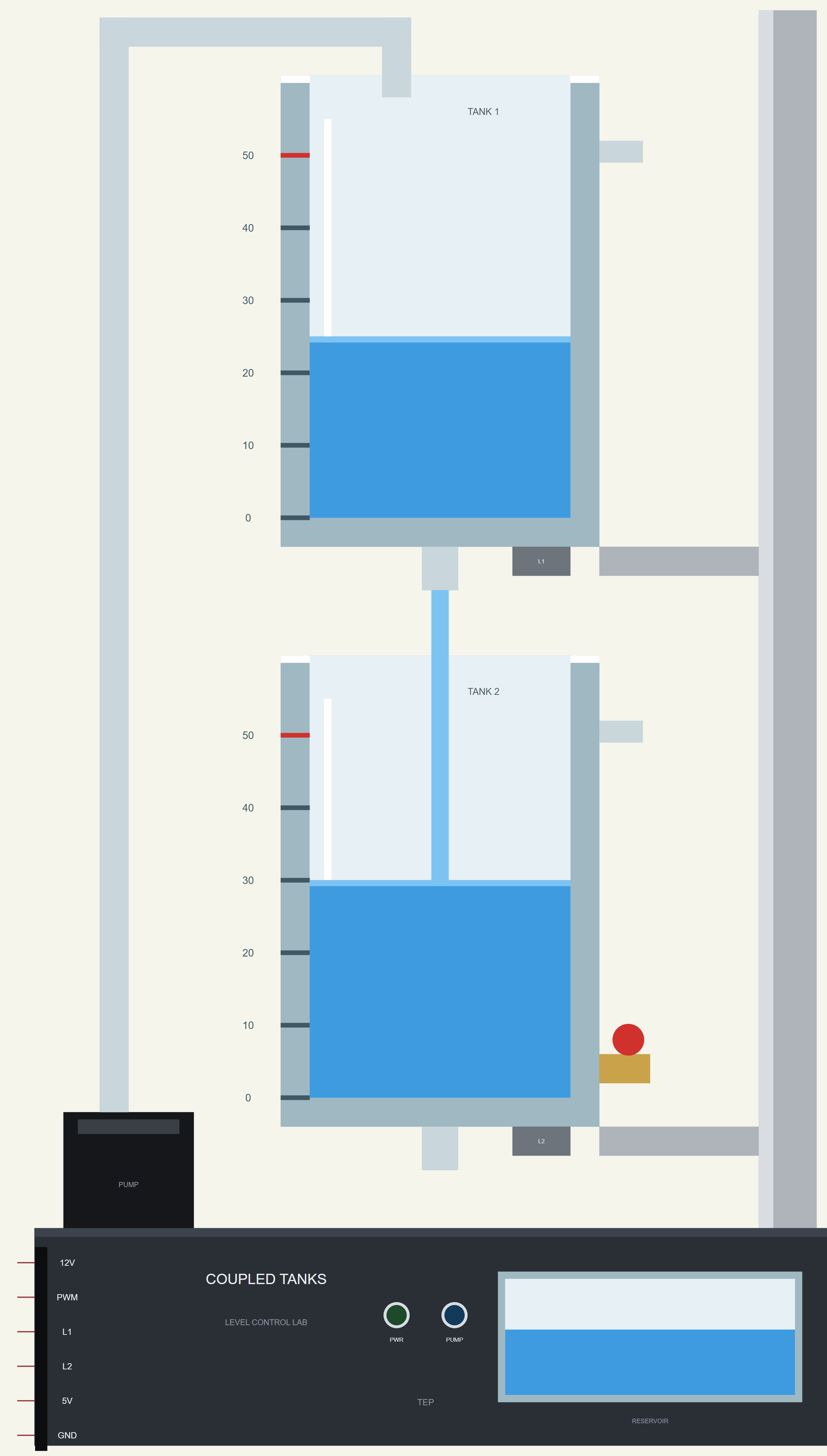
Coupled tanks are two tanks connected so that the water of one feeds the other. In our lab the pump fills tank 1 at the top. Tank 1 drains through a small hole in its floor into tank 2 below, and tank 2 drains through its own hole into the reservoir in the base, where the pump takes the water again. Nothing but the pump is driven. Each tank finds its own level where what flows in equals what flows out. To change the level of tank 2 you must change the level of tank 1, and that takes time. Real plants are full of such chains: boilers, chemical reactors, water treatment, the fuel in an aircraft's tanks.
Our lab is drawn at its true size, seen from the front. At Run the water rises and falls in both tanks, streams fall from the pump's tube into tank 1, from tank 1 into tank 2 and from tank 2 into the reservoir, each thicker as it flows faster. The sight window on the base shows the reservoir's water going down as the tanks fill, and the PUMP LED glows with the pump's duty.
| The coupled tanks lab | |
|---|---|
| Size | 112 x 198 mm |
| Tanks | two, clear, 36 x 36 mm inside; levels 0 - 50 mm, an overflow at 50 mm |
| Orifices | 4 mm in each tank's floor; a 1.5 mm leak valve on tank 2 |
| Pump | 12 V: 1.2 mL/s per volt above 1.5 V, a 0.3 s lag, driven by a MOSFET on the base |
| Sensors | one under each tank: 0.5 V + 80 mV per mm of water |
| Pins | 12V, PWM (the pump), L1, L2 (the sensors), 5V, GND |
Torricelli's Law
Water leaves a hole in a tank's floor as fast as if it had fallen from the water's surface: v = √(2 g h). The flow is that speed times the hole's area, times a discharge coefficient of about 0.62 for a sharp-edged hole. So the outflow grows with the square root of the level. A tank at 36 mm drains only 20 % faster than one at 25 mm, not 44 % faster. That square root is what makes a tank nonlinear: its gain and its time constant both change with the level. Our model works out each tank's level from its inflow and outflow every simulation step.
The Linear Model at a Level
Around one level the square root looks like a straight line, and each tank becomes a first-order system: a gain and a time constant, τ = 2 A √h / (Cd a √(2g)). For our tanks at 25 mm the pop-up finds 11.9 s and 11.0 mm of level per volt on the pump; holding 25 mm takes 6.05 V. Tank 2 follows tank 1 with the same time constant and a gain of one, because the two holes are the same size. Seen from the pump, tank 2 is two first-order systems in a row: a second-order plant, slower and harder to control than tank 1.
PI with a Feed-Forward
The top tank needs a PI controller. The proportional part pushes the pump harder when the level is low; the integral removes the last offset. In front of it goes a feed-forward: the voltage that would hold the target level by itself, worked out from Torricelli's law. Then the PI only has to correct the small error. Placing the closed loop's poles at the speed you choose (the WN property, 0.6 rad/s by default) and ζ = 0.8 gives Kp = 0.946 V per mm and Ki = 0.389 V per mm per second. The integral is held while the pump is at a limit, so it does not wind up while the tank fills.
Cascade Control
For tank 2 the demo uses a cascade. An outer PI looks at tank 2's level and decides what tank 1's level should be. The inner PI on tank 1 then drives the pump to get it. The inner loop handles the fast part and any disturbance in tank 1 before it reaches tank 2; the outer loop only has to deal with a first-order plant. The rule is that the inner loop must be several times faster than the outer one. The pop-up designs the outer loop five times slower, at WN / 5 and ζ = 1: Kp = 1.85 mm per mm and Ki = 0.171 per second.
Features of the Coupled Tanks Level Control Lab Library for Proteus
- The real look, at true scale: a 112 x 198 mm lab with two clear tanks, a pump and its tube, sensors and a leak valve; at Run the water moves, the streams flow, the reservoir goes down.
- Real physics: Torricelli outflows, the pump's flow and lag, the overflows, a leak.
- Exact pump timing: every edge of the pump's PWM is timed.
- The model at the levels: the time constant, the gain and the holding voltage, worked out where tank 1 sits.
- PI and cascade gains: for the speed you choose (WN), in volts and in millimetres.
- Everything measured: every level move (rise, overshoot, peak, settling) and the leak (the dip, the recovery).
- A pop-up: the tanks with their water and streams, both levels and the pump since the start, eight live values, graphs, an event log and a check page.
- A complete package: about 1.2 MB with the library, our Arduino UNO V4.0 and the demo, without the source code of the model.
The Coupled Tanks in Proteus
The device is COUPLEDTANKSTEP in TEPTANKS.LIB, under Control Labs, with the prefix U and the model TEPTANKS.DLL, a mixed model: the pump's gate is digital and timed edge by edge, the sensors and the supplies are analog. Search TANKS in Pick Devices. Its six pins are on the left edge of the base: 12V for the pump, PWM for the pump MOSFET's gate, L1 and L2 for the sensors, 5V and GND.
The Properties
| Property | What it does |
|---|---|
| Tank 1 at the start (LEVEL1) | mm of water in the top tank, 0 by default |
| Tank 2 at the start (LEVEL2) | mm of water in the bottom tank, 0 by default |
| Sensor noise (NOISE) | mV RMS on L1 and L2, 2 by default |
| Loop speed (WN) | rad/s: the pop-up's tank-1 PI is for this speed and ζ = 0.8, its cascade for WN / 5; 0.6 by default |
| The leak (LEAK) | the leak valve on tank 2 opens at this time in seconds; 0 = never |
Download Coupled Tanks Level Control Lab Library for Proteus
Click the button below to download Coupled-Tanks-Level-Control-Lab-Library-for-Proteus-v1.0.zip (about 1.2 MB, without the source code of the models):
Coupled Tanks Library for Proteus V1.0- README.txt: installation, the demo, the wiring, troubleshooting and the limits.
- Proteus Library Files:
TEPTANKS.LIBand ourArduinoV4TEP.LIB. - Proteus Model Files:
TEPTANKS.DLLandTEPARDUINO.DLL. - Arduino Code: the demo sketch.
- Proteus Simulation: the demo project, its HEX file and copies of the DLLs.
No Proteus yet? Read How to Download and Install Proteus 7 and 8. New to libraries? Follow How to Install a New Library in Proteus.
How to Install Coupled Tanks Level Control Lab Library for Proteus
- Close Proteus and extract the whole zip file, for example to your Desktop.
- Copy the files from Proteus Library Files into the LIBRARY folder of Proteus.
- Copy the files from Proteus Model Files into the MODELS folder.
- Delete
TEPTANKS.IDXfrom the LIBRARY folder if it is there. - Start Proteus, press P and search for TANKS.
Demo: PI, Cascade and a Leak
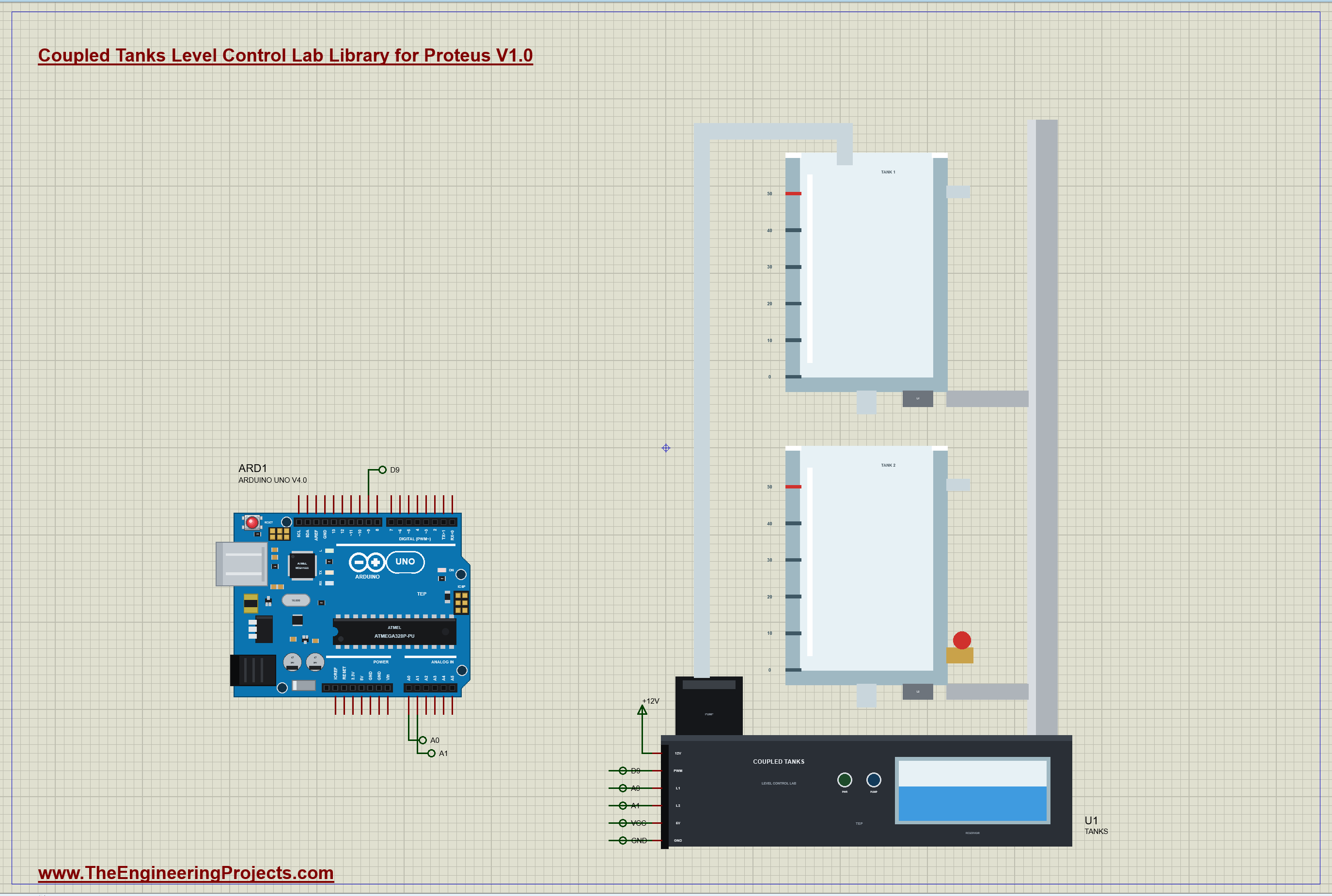
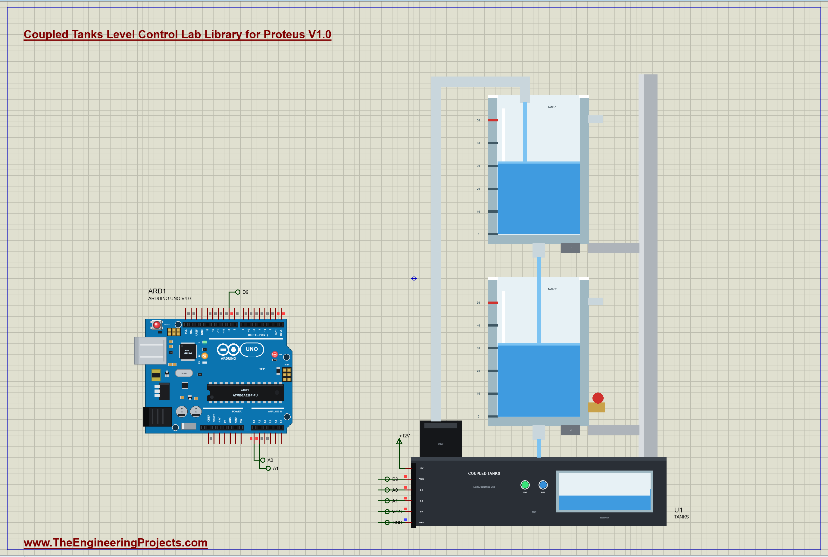
The demo is just the lab and our Arduino UNO Library for Proteus V4.0, with its built-in monitor, the same window as our TEP Serial Monitor Advance for Proteus. The lab's PWM goes to D9, L1 to A0 and L2 to A1, 5V and GND to the rails, and 12V to a +12V terminal. The lab's LEAK property is set to 175 s. Open CoupledTanks-PI-ArduinoUnoV4.pdsprj; the sheet is A3, because the lab is 198 mm tall at true scale.
The Sketch
Every 100 ms the sketch reads both sensors and turns their voltages into millimetres of water. Tank 1's loop is the feed-forward, the voltage that holds the target by Torricelli's law, plus the PI. The integral only counts while the pump is not at a limit:
  float e1 = r1 - h1;
  float u = V0 + AQ * sqrt(max(r1, 0.0)) / KQ + KP * e1 + i1;
  if (u > 0 && u < VS) i1 += KI * e1 * dt;
Once the cascade is on, tank 2's error sets tank 1's target, limited to the levels the tanks can take:
  if (cascade) {
    float e2 = r2 - h2;
    i2 = constrain(i2 + KIO * e2 * dt, -20, 20);
    r1 = constrain(r2 + KPO * e2 + i2, 5, 45);
  }
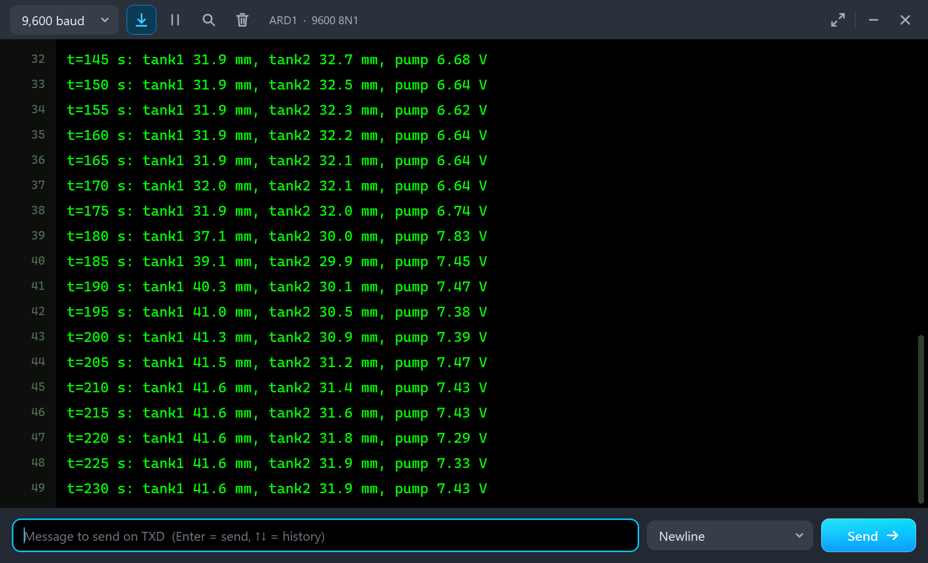
Tank 1 fills to 25 mm, steps to 35 mm at 20 s and back to 25 mm at 40 s. At 60 s the cascade takes over with tank 2 at 25 mm, then 32 mm at 110 s. At 175 s the lab opens the leak. Every 5 s the sketch prints both levels and the pump's voltage.
Run the Demo
Open the project and press Run. The demo runs 232 simulated seconds, which Proteus ran in about 12 minutes on our PC; the tanks are slow, so it takes a while. Click the lab to open its pop-up; everything below is from that one run, the demo exactly as it ships.
Filling and the Tank 1 Steps
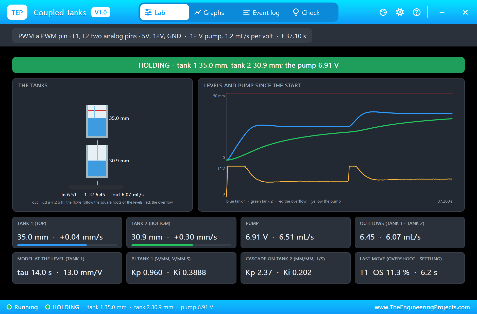
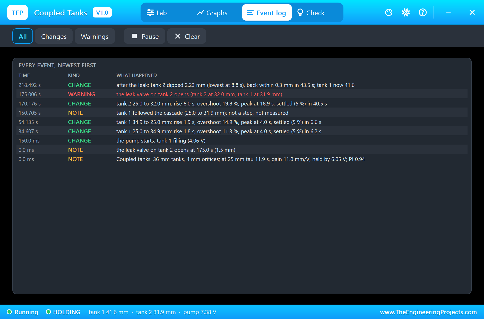
The pump starts at full voltage and tank 1 fills to 25 mm in a few seconds; the integral waits while the pump is at its limit, so the level arrives without a big overshoot. Tank 2 fills more slowly behind it. At 20 s the target jumps to 35 mm. The level rises in 1.8 s from 10 to 90 %, overshoots by 11.3 % with the peak at 4.0 s, and settles within 5 % in 6.2 s. At 40 s it comes back down to 25 mm: a rise of 1.9 s, 14.9 % overshoot and 6.6 s to settle. The way down overshoots a little more because the pump can only stop, not suck water out; the tank drains at its own pace.
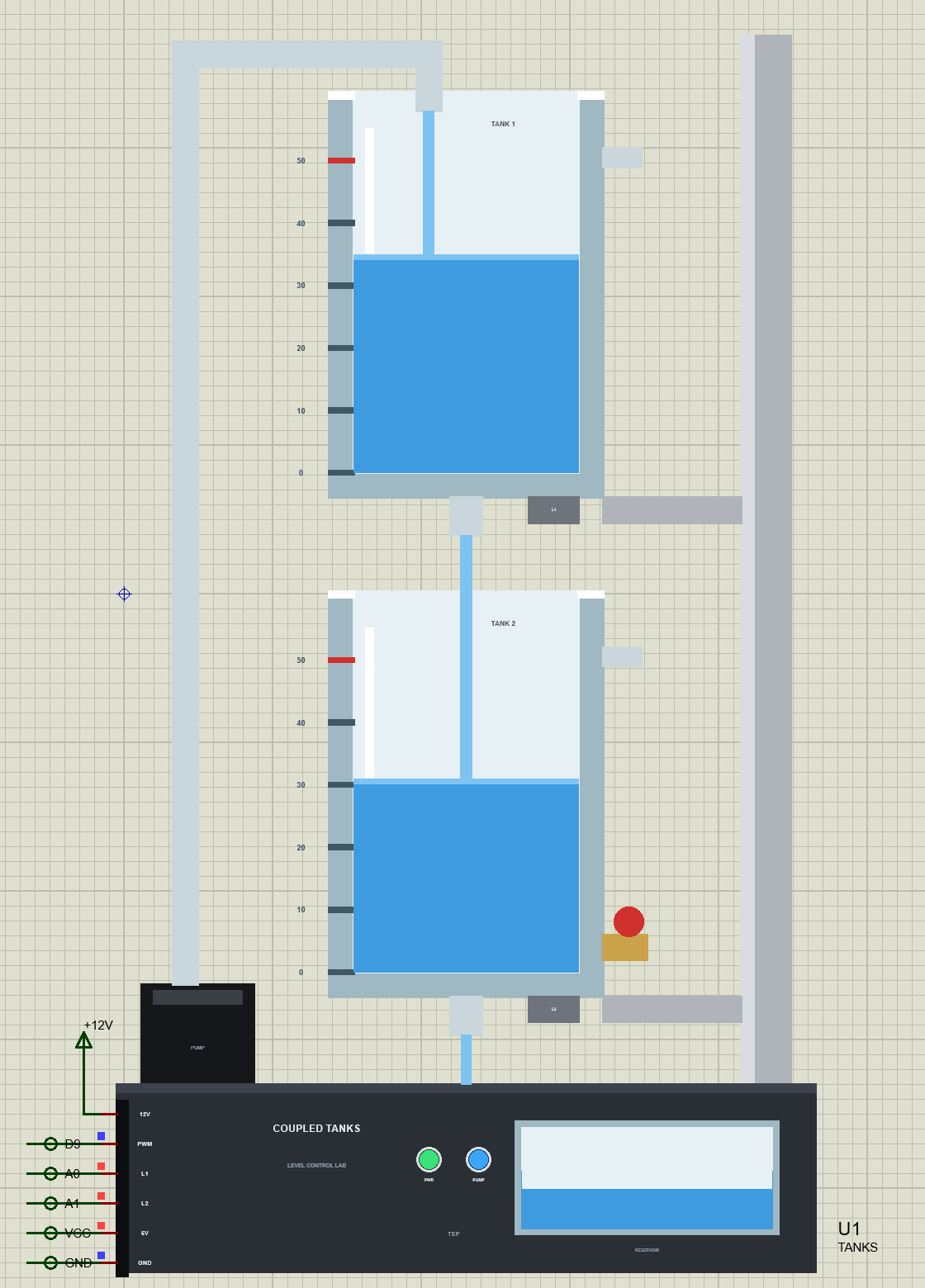
The pop-up opened at 37 s shows tank 1 holding 35.0 mm with the pump at 6.91 V, tank 2 still rising behind it at 30.9 mm, and the first move's numbers. Its model is now worked out at 35 mm: a time constant of 14.0 s and 13.0 mm per volt. The tank is slower and has more gain at a higher level, exactly as the square root says.
The Cascade on Tank 2
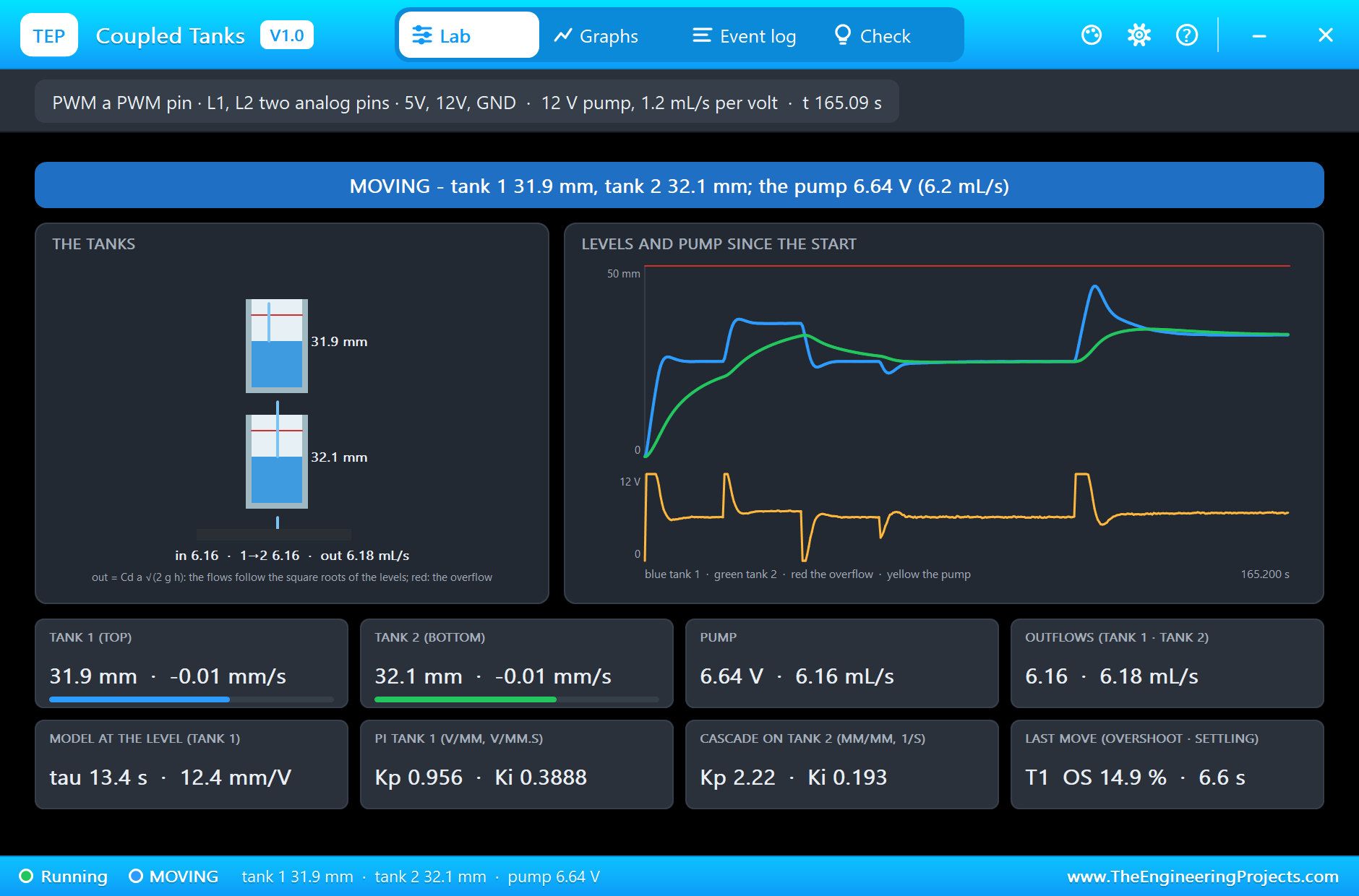
At 60 s the cascade takes over with tank 2 at 25 mm, and at 110 s its target goes to 32 mm. The outer loop asks for far more than 32 mm in tank 1 at first, to push water into tank 2 quickly; the inner loop follows and the pump runs at full voltage for a moment. Tank 2 rises in 6.0 s, overshoots by 19.8 % with the peak at 18.9 s, and settles within 5 % in 40.5 s, with tank 1 settling at 31.9 mm. The Event log notes that tank 1's own move during the cascade was not measured: the outer loop was driving it, so it was not a step.
The Leak
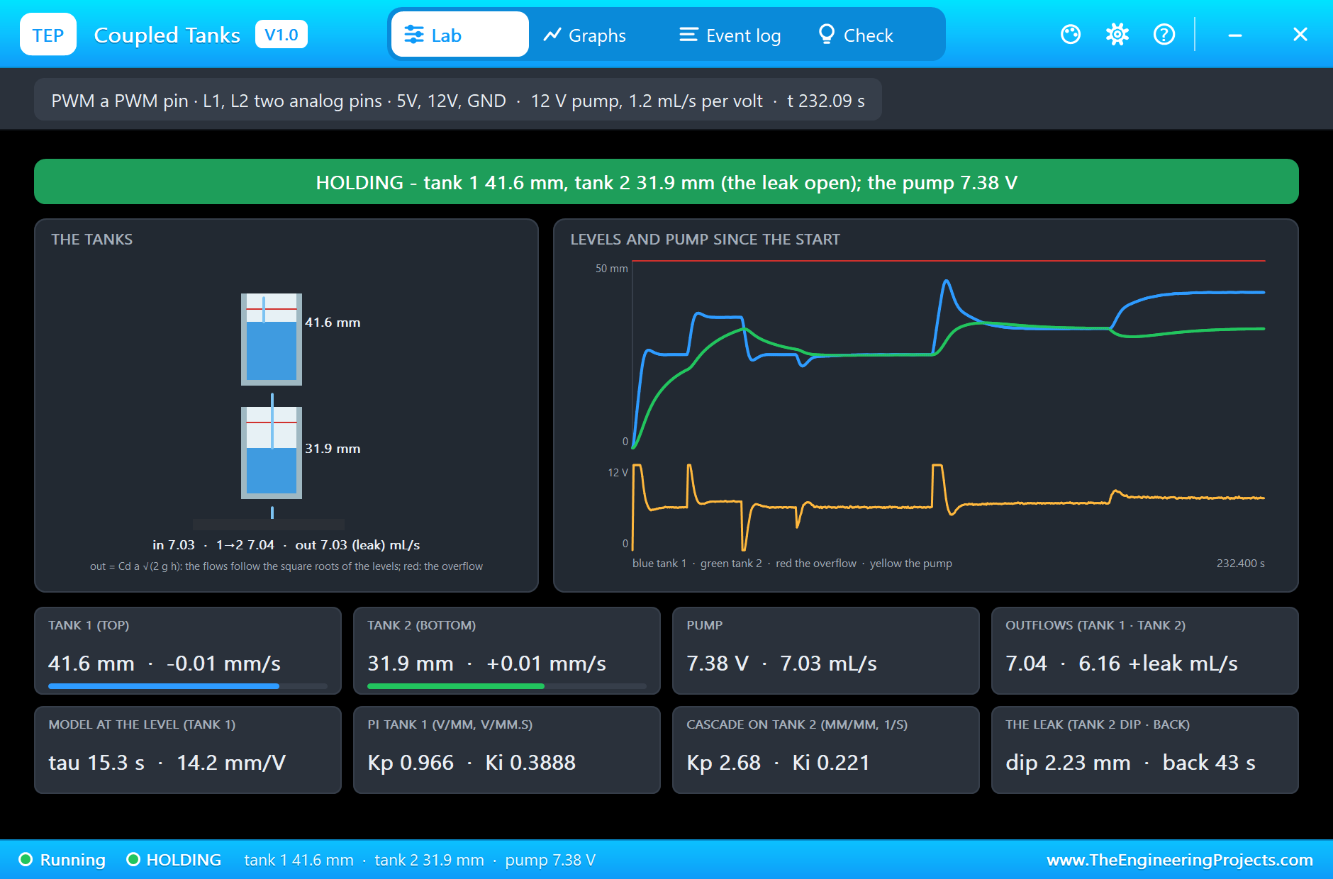
At 175 s the lab opens the 1.5 mm leak valve on tank 2. Tank 2 loses water faster than tank 1 feeds it and starts to fall. The outer loop sees the error and raises tank 1's target; tank 1 climbs to 41.6 mm, so that more water runs into tank 2. Tank 2 dips 2.23 mm, from 32.00 to 29.77 mm, at its lowest 8.8 s after the leak opened. It is back within 0.3 mm of 32 mm in 43.5 s, with the pump now at 7.4 V, and no tank overflows. A single loop from the pump to tank 2 would have fought the leak through two tanks' worth of lag; the cascade puts the extra water where it is needed.
The Monitor
The UNO's monitor prints both levels and the pump every 5 s: tank 2 at 32.5 mm and tank 1 at 31.9 mm at 150 s, the leak's dip to 30.0 mm at 180 s with tank 1 already at 37.1 mm, and at 230 s tank 2 back at 31.9 mm with tank 1 at 41.6 mm and the pump at 7.43 V.
The Graphs, the Log and the Check Page
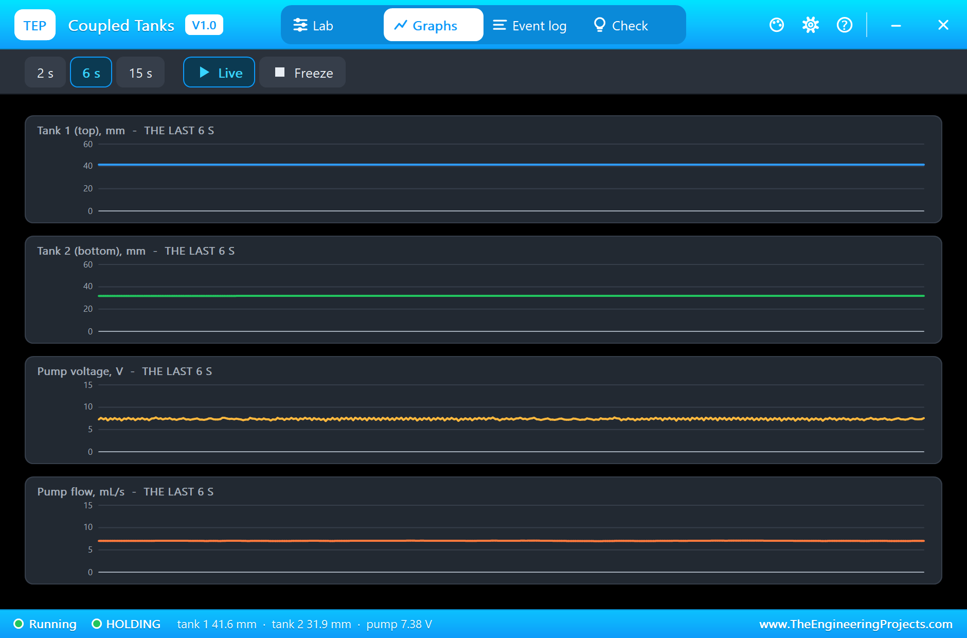
The Graphs page plots both levels, the pump's voltage and its flow over the last 2, 6 or 15 simulated seconds; the main page's trend covers the whole run. The Event log lists the start of the pump, every move with its numbers, the leak and the recovery.
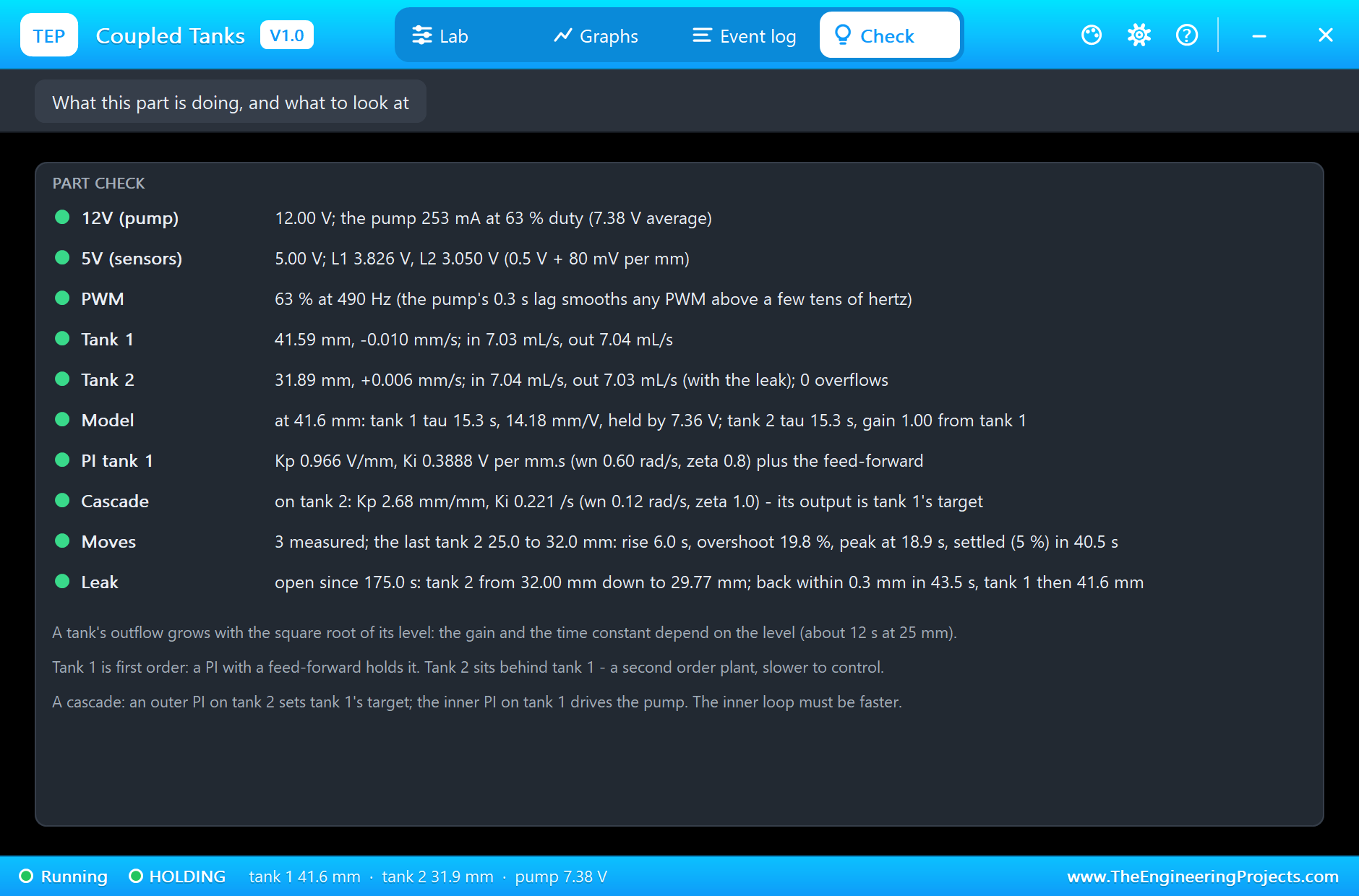
The Check page sums up the part: the 12 V supply with the pump's current, the sensors on 5 V, the PWM, both tanks with their flows in and out, the model at the level tank 1 holds, the PI and the cascade gains, the last move and the leak.
Try It Yourself
- Set WN to 1.0, copy the pop-up's new gains into the sketch, and see tank 1 move faster with more overshoot.
- Remove the feed-forward from the sketch and watch the integral do all the work, more slowly.
- Make the cascade's outer loop as fast as the inner one and see tank 2 start to swing.
- Set LEAK to an earlier time and a higher target for tank 2, and find when the pump runs out of room.
- Start with LEVEL1 at 50 and LEVEL2 at 0 and watch the tanks drain into each other with the pump off.
Ideas to Extend the Demo
- Control tank 2 directly from the pump with one PI and compare it with the cascade.
- Add a potentiometer for tank 2's target and set the level by hand.
- Send both levels to a PC and fit the time constants from a step.
- Linearize the pump with its 1.5 V dead zone in the feed-forward and see what it does for small targets.
Your Own Sketches
The demo sketch is in the zip file, and you can change it in the Arduino IDE. New to Arduino? Start with our Arduino Tutorial for Beginners. Export the compiled binary, and set the UNO's PROGRAM property to the new file. Our guide on How to get the HEX file from Arduino shows you where the file ends up.
Things to Know Before Using a Real Lab
- Keep the electronics dry: a real rig drips, and the pump's leads carry 12 V.
- Calibrate the sensors: real orifices clog and real sensors drift; check them with the tanks empty and full.
- Prime the pump: air in a pump stops it pumping; keep its intake under the reservoir's water.
- Keep the overflows: a controller that saturates will fill a tank to the brim.
Troubleshooting
- NO 12 V: the gate is driven but 12V is missing, so the pump cannot run.
- OVERFLOW: a tank is at 50 mm and spilling; the target is too high, or the loop's sign is wrong: a level too low must raise the pump.
- The levels read wrong: 5V is missing, or the sketch's scale is not 0.5 V + 80 mV per mm.
- Tank 2 swings slowly around its target: the cascade's outer loop is too fast for the inner one; slow it down.
- The part is not simulated:
TEPTANKS.DLLis missing from MODELS and from the project folder.
Limitations of the Simulation
- The water's inertia in the tubes, waves and splashing are not modelled.
- The sensors do not drift with temperature, and the reservoir never runs dry.
- The pump's flow is a straight line above 1.5 V; a real pump's curve bends.
- Arduino is a name of Arduino; this library is not made or endorsed by Arduino or Labcenter.
- Tested in Proteus 8.5 in November 2026 (the demo as shipped). Proteus 7 is not supported.
So, that was all about the Coupled Tanks Level Control Lab Library for Proteus. I hope it helps you run the classic process control lab on your own PC: Torricelli's square root, a PI with a feed-forward, a cascade that reaches a tank it cannot drive directly, and a leak to test it. If you have any questions, ask in the comments and I will help you out. Till the next tutorial, take care and have fun!

Comments
0