


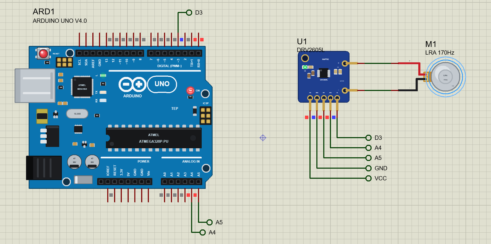
DRV2605L Haptic Driver Library for Proteus Simulation


Hello friends, I hope you all are doing great. Today, I am going to share the new DRV2605L Haptic Driver Library for Proteus Simulation, the 37th library of our motor series. If you have searched for a Proteus simulation of the DRV2605L, this is the small chip behind the taps and buzzes of phones, watches and game controllers: a haptic driver from Texas Instruments that plays ready-made effects on an LRA or an ERM vibration motor over I2C. Instead of switching the motor yourself, you write an effect number into a register, set GO, and the chip plays a crisp click with its own overdrive and brake.
DRV2605L Haptic Driver Library for Proteus Simulation
Latest version: V1.0 (November 2026, this tutorial)
Helping Tools
- Serial Monitor Advance: a serial terminal window for the UART of your board
- Serial Monitor Expert: the serial monitor with extra debugging tools
- LCD Library for Proteus V3.0: 16x2, 20x4 and I2C LCDs to show your readings
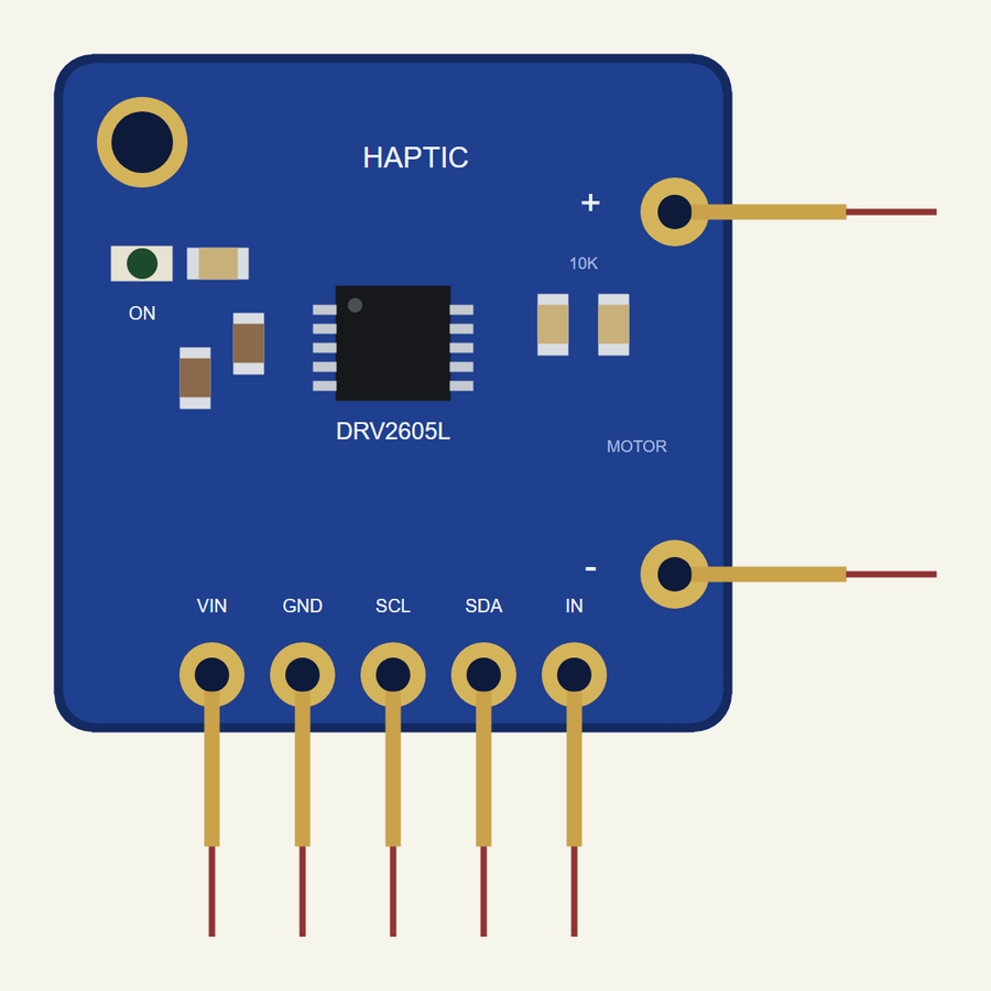
Our library brings a DRV2605L breakout into your Proteus simulation at its true size, 17.8 mm square, with the header for VIN, GND, SCL, SDA and IN and the two motor pads. The simulation model follows TI's datasheet: the register map with its defaults, the modes, the waveform sequencer with its waits, the 123 library effects by name, real-time playback, the auto calibration and the diagnostics. Above all it does what makes the chip special: with an LRA it finds the actuator's own resonance by listening to its back-EMF, and it overdrives and brakes it automatically. The pop-up decodes the registers, shows the sequencer playing and draws the output, driving and listening. In the demo an Arduino talks to it with plain Wire writes and drives our LRA, set off its rating on purpose so you can watch the driver find it.
NOTICE: Our team has put a lot of effort into these small parts: the bodies, the animation and the pop-ups are all our own design, and you get them free. Your feedback is the fuel that keeps us going, so please tell us what you think in the comments below or in the Motor Driver board of our forum. And if our free libraries help you, you can buy us a coffee. So, let's get started with the DRV2605L Haptic Driver Library for Proteus Simulation:
What is the DRV2605L?
The DRV2605L is a haptic driver: an H-bridge for a small vibration motor plus a playback engine and an I2C interface, in a tiny package that runs from 2 to 5.2 V. It drives both kinds of vibration motor. An ERM (eccentric rotating mass) is a DC motor with an off-centre weight; an LRA (linear resonant actuator) is a mass on springs pushed by a voice coil, which only shakes well at its resonance. The chip stores a licensed library of 123 effects, clicks, ticks, bumps, buzzes, pulses and ramps, so a microcontroller only has to name the effect.
Its smart loop is the reason engineers pick it. In closed loop the DRV2605L watches the motor's back-EMF, the voltage the moving motor generates itself. For an LRA it uses that to find the resonance: it pushes, lets go for a moment, listens for the back-EMF to cross zero, and flips the drive there, cycle by cycle, so it follows the actuator even when the resonance drifts. It also overdrives at the start for a fast rise and brakes at the end for a crisp stop. Before that works it needs an auto calibration, which measures the actuator.
| The DRV2605L (TI datasheet) | |
|---|---|
| Supply | 2 to 5.2 V; 0.5 mA quiescent, 4 µA in standby |
| Interface | I2C at 0x5A (up to 400 kHz), IN/TRIG pin |
| Actuators | LRA (closed loop with auto-resonance, or open loop) and ERM (closed or open loop) |
| Modes | internal trigger, external edge / level trigger, PWM / analog input, audio-to-vibe, real-time playback, diagnostics, auto calibration |
| Library | 6 ERM libraries and 1 LRA library, 123 effects; a sequencer of 8 slots with waits |
| Protection | over-current (a load under 4 ohm), over-temperature |
Features of the DRV2605L Haptic Driver Library for Proteus Simulation
- The breakout at true scale: the 17.8 mm board with the DRV2605L, its capacitors and I2C pull-ups, the header and the motor pads; the ON LED lights at run time.
- The real register map: 0x00 to 0x22 with the datasheet's defaults: it starts in standby, as an ERM in open loop, until you set it up.
- The modes: internal trigger with GO, external edge and level trigger on IN, PWM input, real-time playback, diagnostics and auto calibration.
- The sequencer and the effects: 8 slots with 10 ms waits, the 123 effects by their datasheet names, played from their names and strengths.
- LRA auto-resonance: drive, let go, listen to the back-EMF, flip at its zero crossing; LRA_PERIOD reports the resonance.
- Automatic overdrive and braking: the closed loop drives up to the overdrive clamp at the start and against the motion at the end.
- Auto calibration and diagnostics: the actuator's resistance and back-EMF stored in A_CAL_COMP, A_CAL_BEMF and BEMF_GAIN; open or shorted actuators found.
- A pop-up: the registers decoded, the playback with its slots and level, the output driving and listening, eight live values, graphs, an event log and a check page.
- A complete package: about 1.2 MB with the library, our Arduino UNO V4.0 and the demo, without the source code of the model.
The DRV2605L in Proteus
The device is DRV2605LTEP in TEPDRV2605.LIB, under Electromechanical > Motor Drivers, with the prefix U and the mixed model TEPDRV2605.DLL. Search DRV2605 in Pick Devices. The header along the bottom has VIN, GND, SCL, SDA and IN; the motor pads on the right are OUT+ and OUT-, 400 thou apart, the same spacing as the leads of our LRA and coin motor libraries. The I2C address is fixed at 0x5A. There are no properties to set: like the real chip, everything is set through its registers.
Download DRV2605L Haptic Driver Library for Proteus Simulation
Click the button below to download DRV2605L-Haptic-Driver-Library-for-Proteus-v1.0.zip (about 1.2 MB, without the source code of the models):
DRV2605L Haptic Driver Library for Proteus V1.0- README.txt: installation, the demo, the wiring, troubleshooting and the limits of the simulation.
- Proteus Library Files:
TEPDRV2605.LIBandArduinoV4TEP.LIB. - Proteus Model Files:
TEPDRV2605.DLLandTEPARDUINO.DLL. - Arduino Code: the demo sketch.
- Proteus Simulation: the demo project, its HEX file and copies of the DLLs.
No Proteus yet? Read How to Download and Install Proteus 7 and 8. New to libraries? Follow How to Install a New Library in Proteus.
How to Install DRV2605L Haptic Driver Library for Proteus Simulation
- Close Proteus and extract the whole zip file, for example to your Desktop.
- Copy the files from Proteus Library Files into the LIBRARY folder of Proteus.
- Copy the files from Proteus Model Files into the MODELS folder.
- Delete
TEPDRV2605.IDXfrom the LIBRARY folder if it is there. - The demo's actuator is our separate LRA Vibration Motor Library for Proteus Simulation: install its LIB and DLL too.
- Start Proteus, press P and search for DRV2605.
Proteus Simulation of the DRV2605L with Arduino
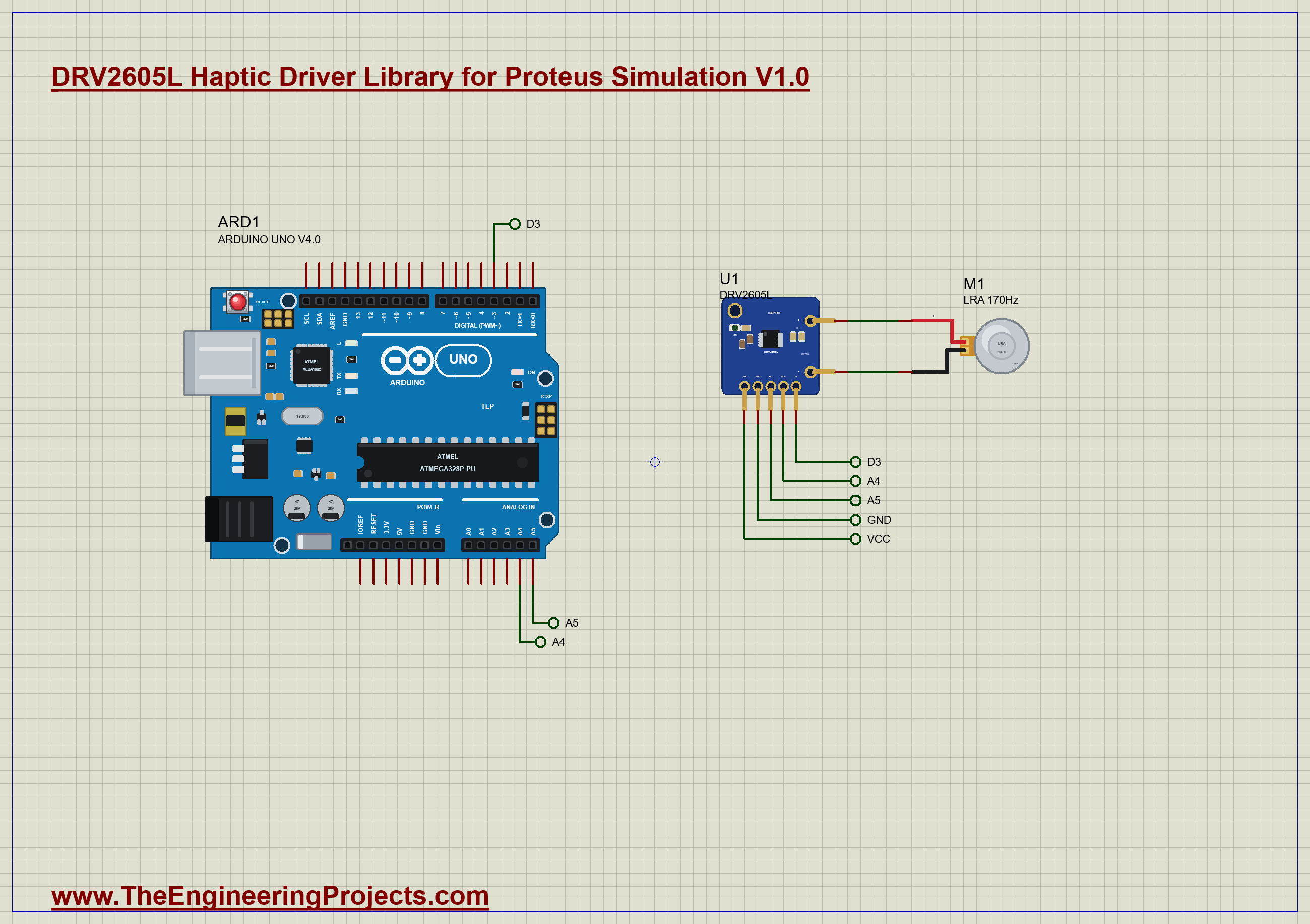
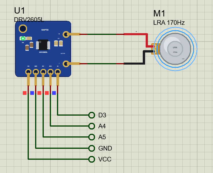
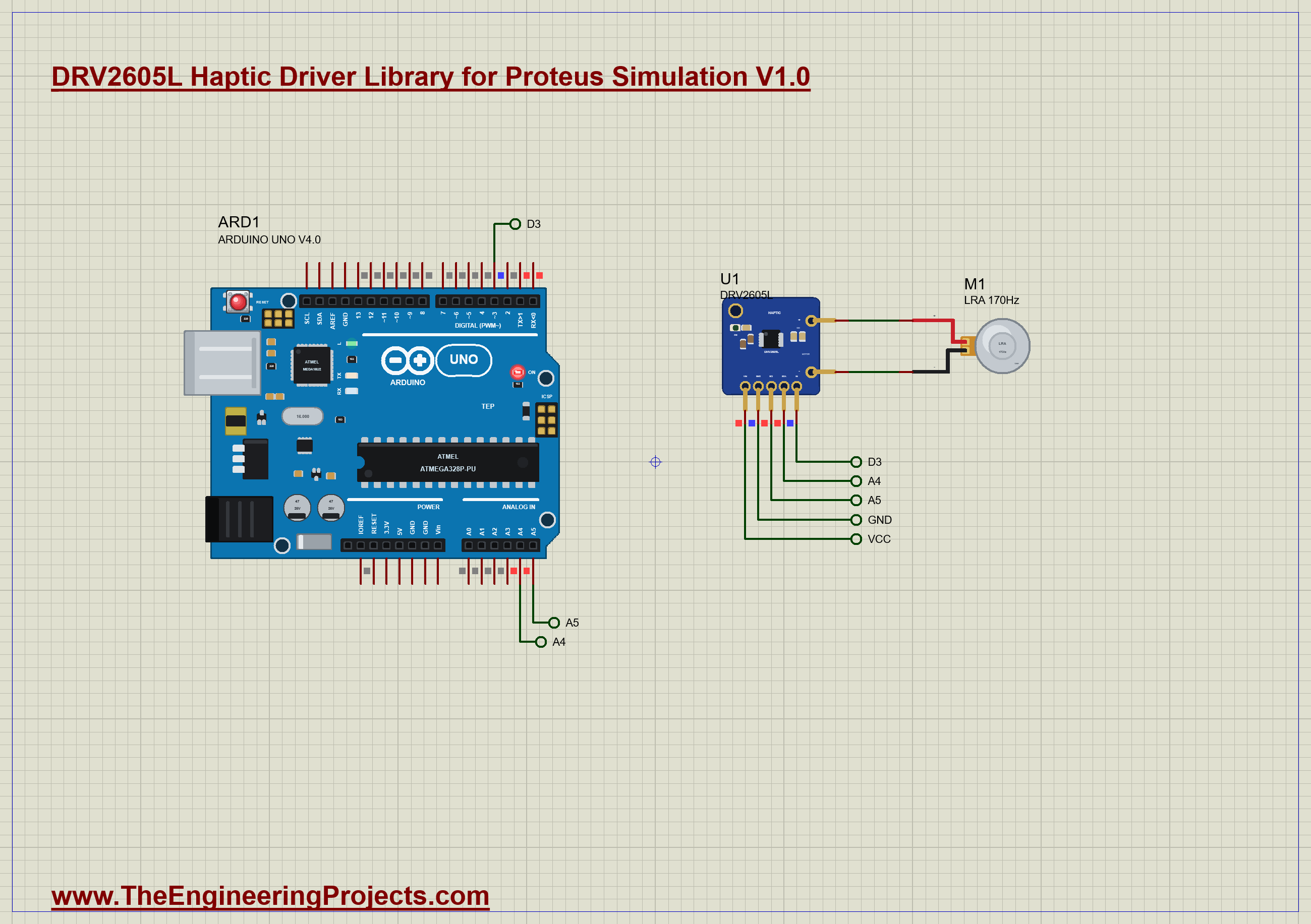
The demo has our Arduino UNO Library for Proteus V4.0 with its built-in monitor, the same window as our TEP Serial Monitor Advance for Proteus. The UNO's A4 and A5 are the I2C pins, labelled to the breakout's SDA and SCL; VIN is on the 5 V rail; IN goes to D3, held low, ready for your own trigger experiments. OUT+ and OUT- go straight to the LRA M1 from our separate LRA library (TEPLRA10.LIB and TEPLRA10.DLL), so install it first. Its resonance is set to 170 Hz instead of its rated 175 Hz: real LRAs spread over 174 ± 8 Hz, and the point of auto-resonance is to find the part you actually have. Open DRV2605L-LRA-ArduinoUnoV4.pdsprj.
The Sketch
The sketch needs no driver library: two small functions write and read a register with the Wire library.
void wr(uint8_t reg, uint8_t v) { Wire.beginTransmission(DRV); Wire.write(reg); Wire.write(v); Wire.endTransmission(); }The setup takes the chip out of standby, switches it to an LRA, writes the rated voltage and the overdrive clamp, sets the first guess of the half period and runs the auto calibration. RATED_VOLTAGE 0x53 gives 2 Vrms for a 175 Hz LRA by the datasheet's formula, and OD_CLAMP 0x89 allows 2.9 V peak:
  wr(FEEDBACK, rd(FEEDBACK) | 0x80);                                    // N_ERM_LRA = 1: an LRA
  wr(RATED, 0x53);                                                      // 2.0 Vrms at 175 Hz
  wr(CLAMP, 0x89);                                                      // 2.9 V peak
An effect is two writes: the effect number into the first sequencer slot, a zero into the next, and then GO:
void play(uint8_t effect) { wr(MODE, 0x00); wr(SEQ1, effect); wr(SEQ1 + 1, 0); wr(GO, 1); }After the program you can type commands in the monitor: e 47 plays effect 47, r 80 sets a real-time level of 80 % and s stops.
DRV2605L Simulation Results
Open the project and press Run. The program runs about 8.4 simulated seconds, which Proteus ran in a few minutes on our PC with both pop-ups open and the pictures being taken. Click the breakout to open its pop-up. Every number below comes from one simulation run, the demo exactly as it ships.
The Auto Calibration
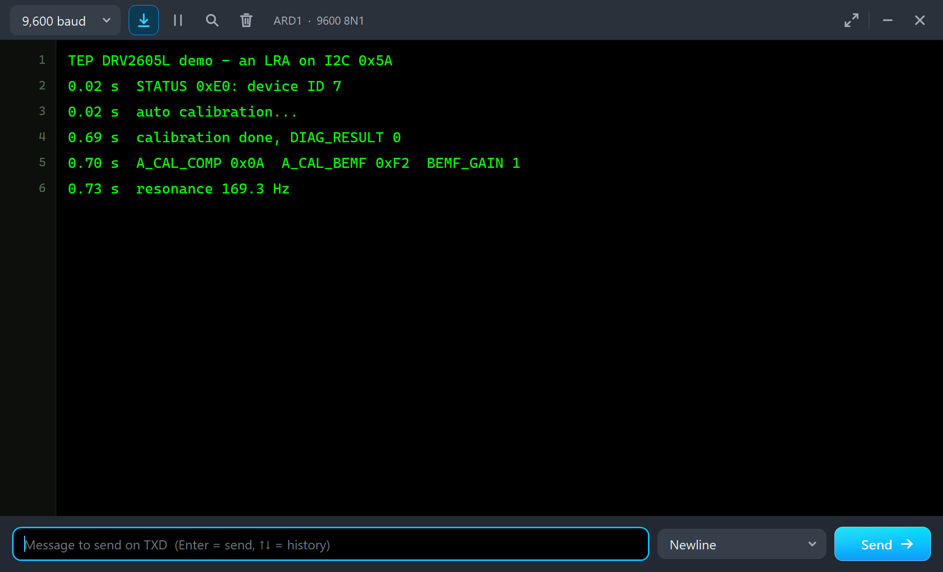
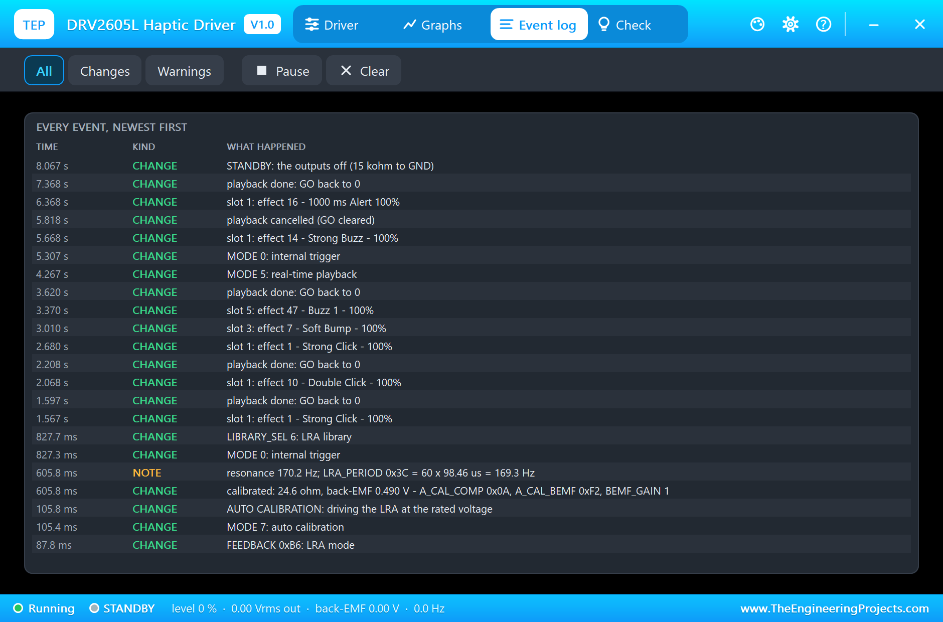
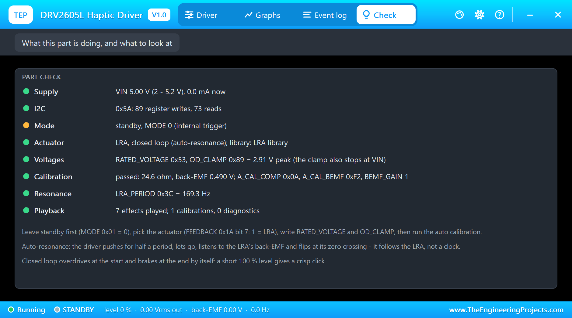
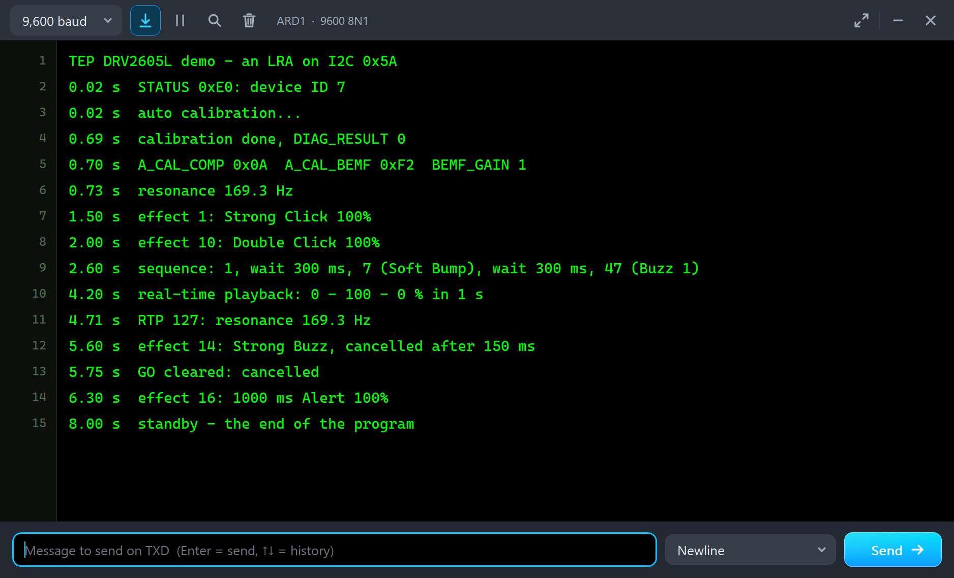
Right after power-on the sketch reads STATUS, 0xE0: device ID 7, a DRV2605L. It sets the chip up and starts the AUTO CALIBRATION: MODE 7 and GO. For half a second the driver plays the LRA at the rated voltage with auto-resonance running, then brakes it and clears GO. At 0.69 s the monitor prints DIAG_RESULT 0, a pass, and the results: A_CAL_COMP 0x0A, A_CAL_BEMF 0xF2 and BEMF_GAIN 1. The Event log adds what the chip measured: 24.6 ohm, and a back-EMF of 0.490 V at the rated voltage. From now on, 100 % in any mode means "make the LRA give that back-EMF".
It also measured the resonance. The register LRA_PERIOD counts the period in steps of 98.46 µs; it reads 0x3C, which is 169.3 Hz, the nearest step to the 170.2 Hz the driver locked on. The LRA is set to 170 Hz, so the driver found it from its first guess of 2.9 ms per half period, a 172 Hz guess.
Effects and the Sequencer
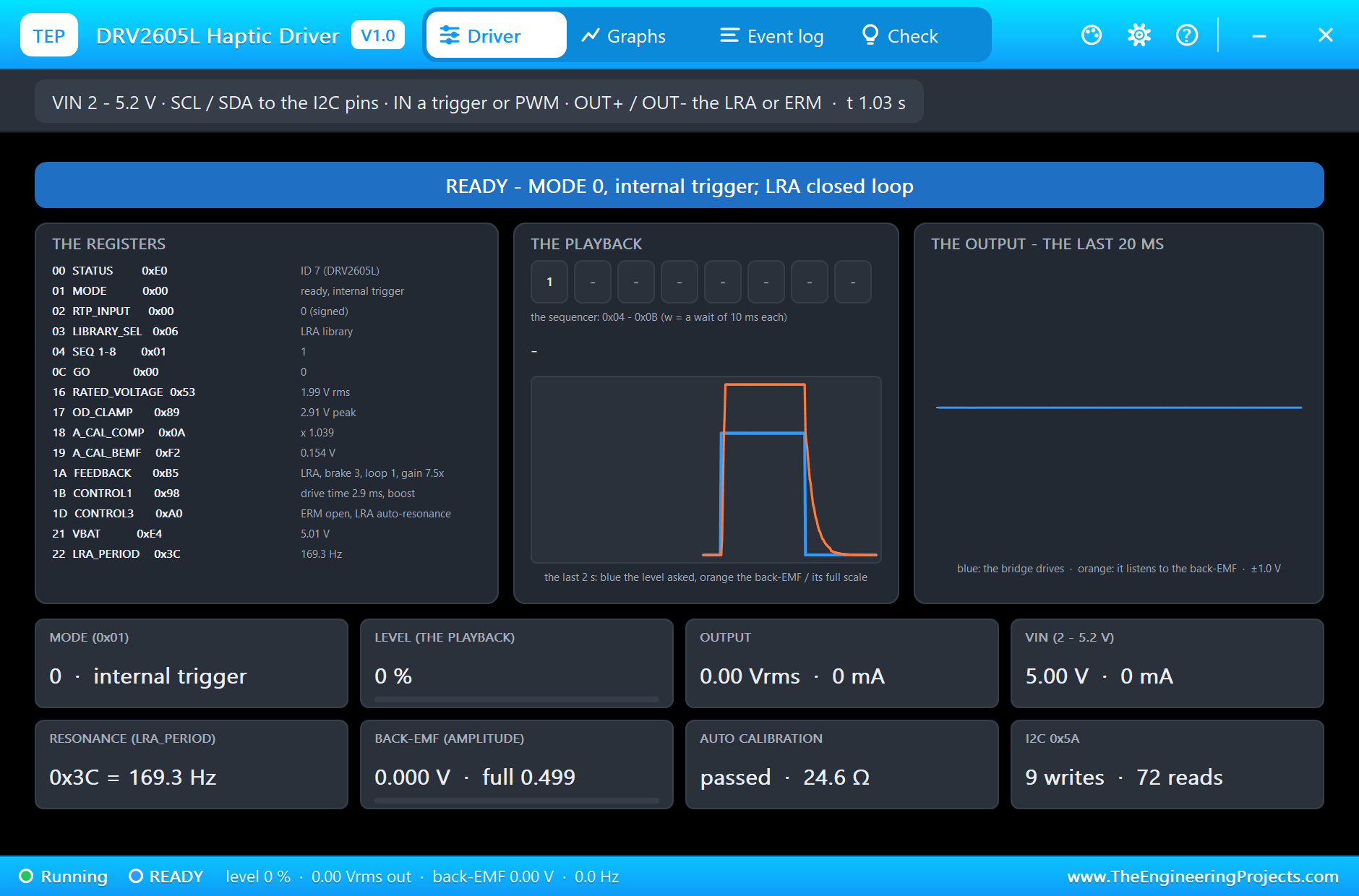
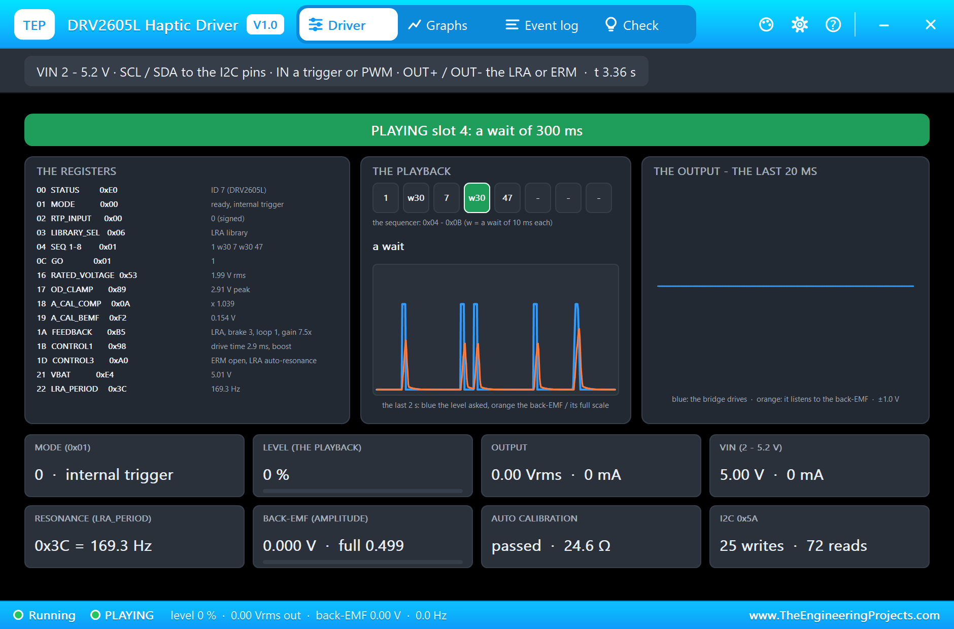
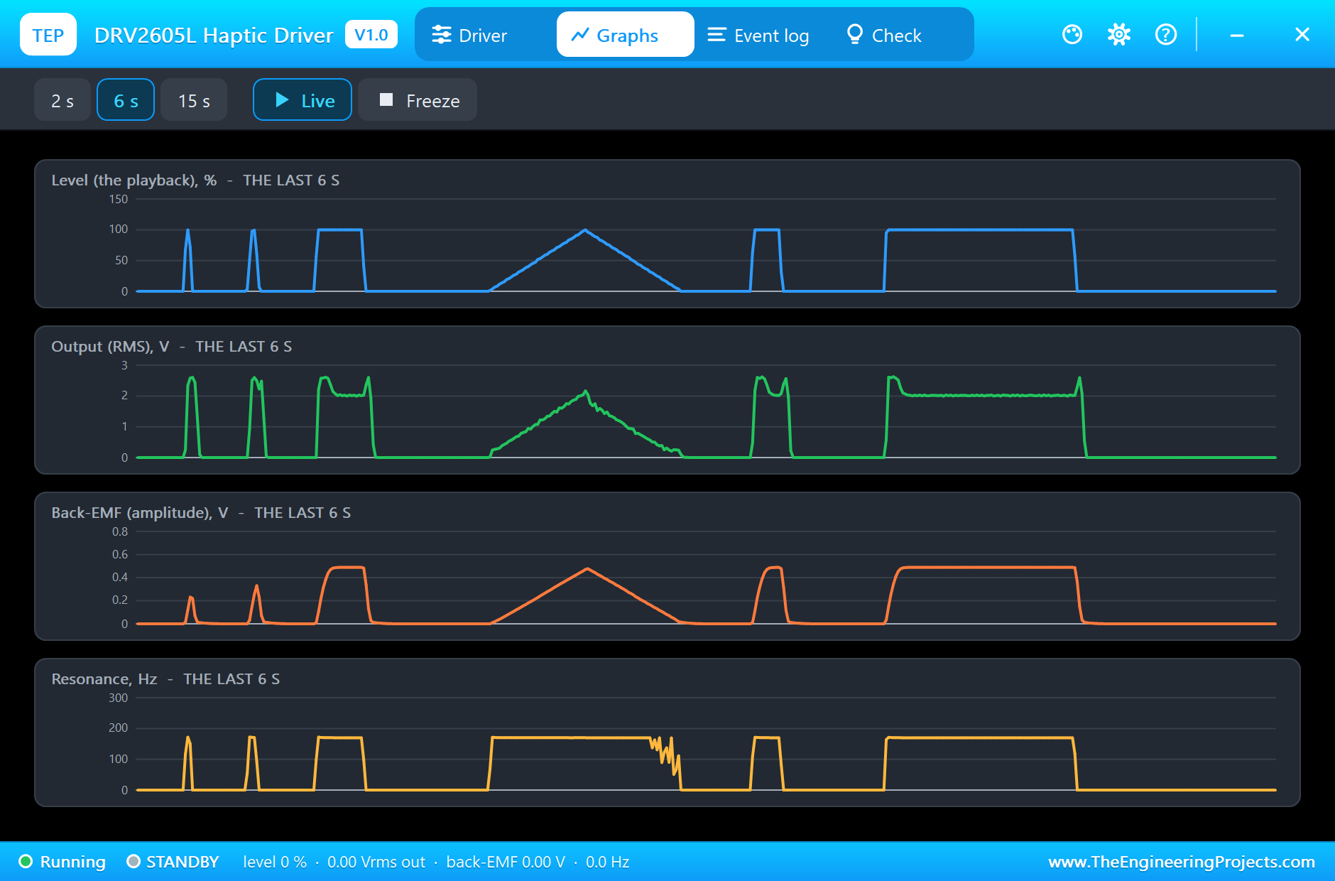
From 1.5 s the sketch plays effect 1, Strong Click 100 %, then effect 10, Double Click 100 %, and at 2.6 s a sequence: Strong Click, a 300 ms wait, Soft Bump, another 300 ms wait, and Buzz 1. In the picture the sequencer is in slot 4, the second wait, with its slot lit in green. The playback trace shows every click so far as a short pulse of level in blue, with the back-EMF in orange rising behind it and falling away: the closed loop overdrives at the start of each effect and drives against the motion at its end. The LRA's own pop-up measured those stops: under 0.04 G in 26 to 29 ms, against the 180 ms an undriven LRA rings on.
Real-Time Playback
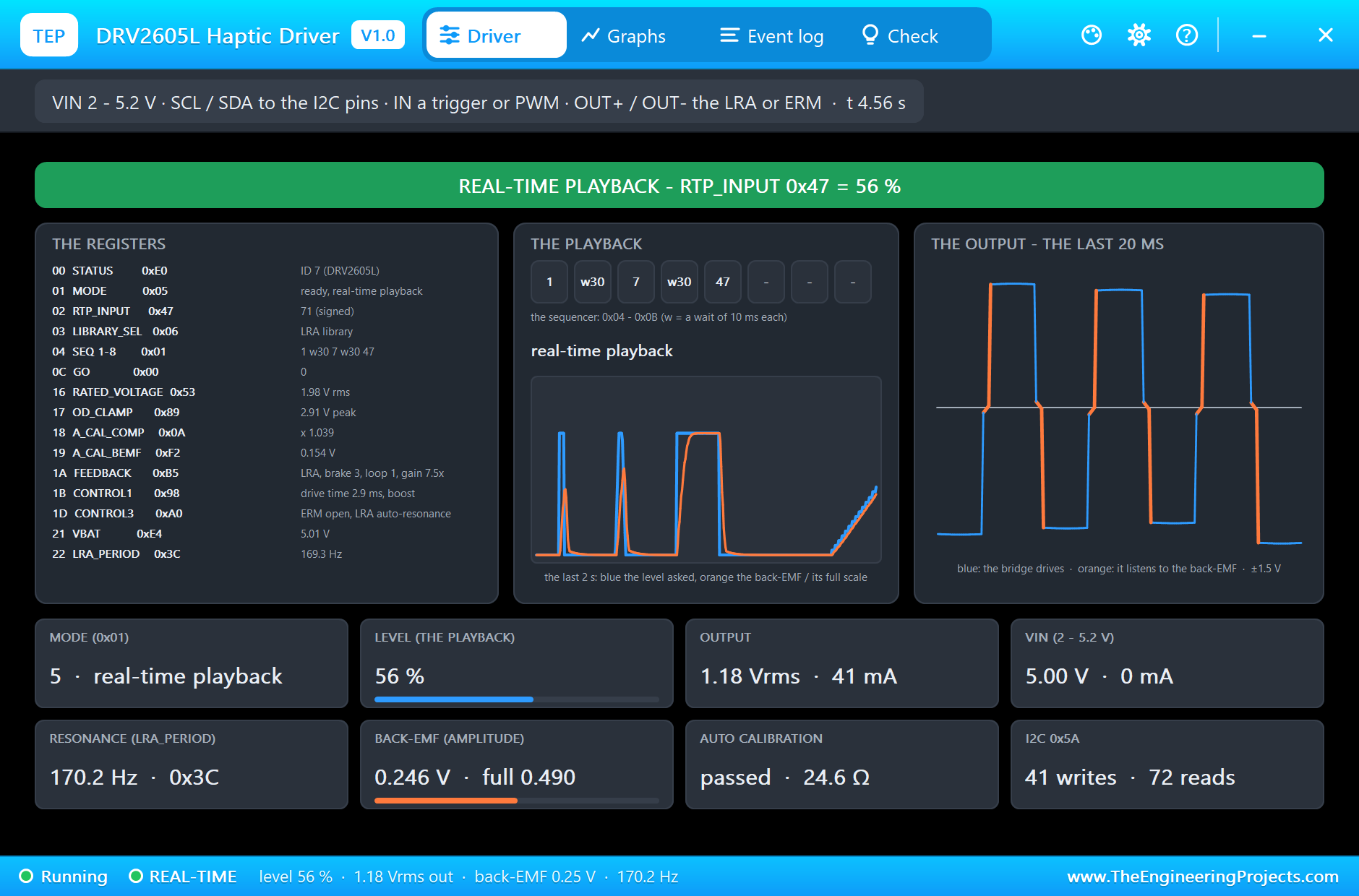
At 4.2 s the sketch switches to MODE 5, real-time playback, and ramps RTP_INPUT from 0 to 127 and back in one second. The level now follows the register directly. In the picture the level is 52 %, the output 1.24 Vrms, and the back-EMF 0.245 V, the same share of its full scale: the loop holds the back-EMF, not the voltage. The driver runs at 170.2 Hz, right on the LRA, which gives 0.70 G. At the top of the ramp the sketch reads LRA_PERIOD again: 169.3 Hz.
On the sheet the breakout's ON LED is lit and the LRA shows its vibration rings.
Cancel and a 1000 ms Alert
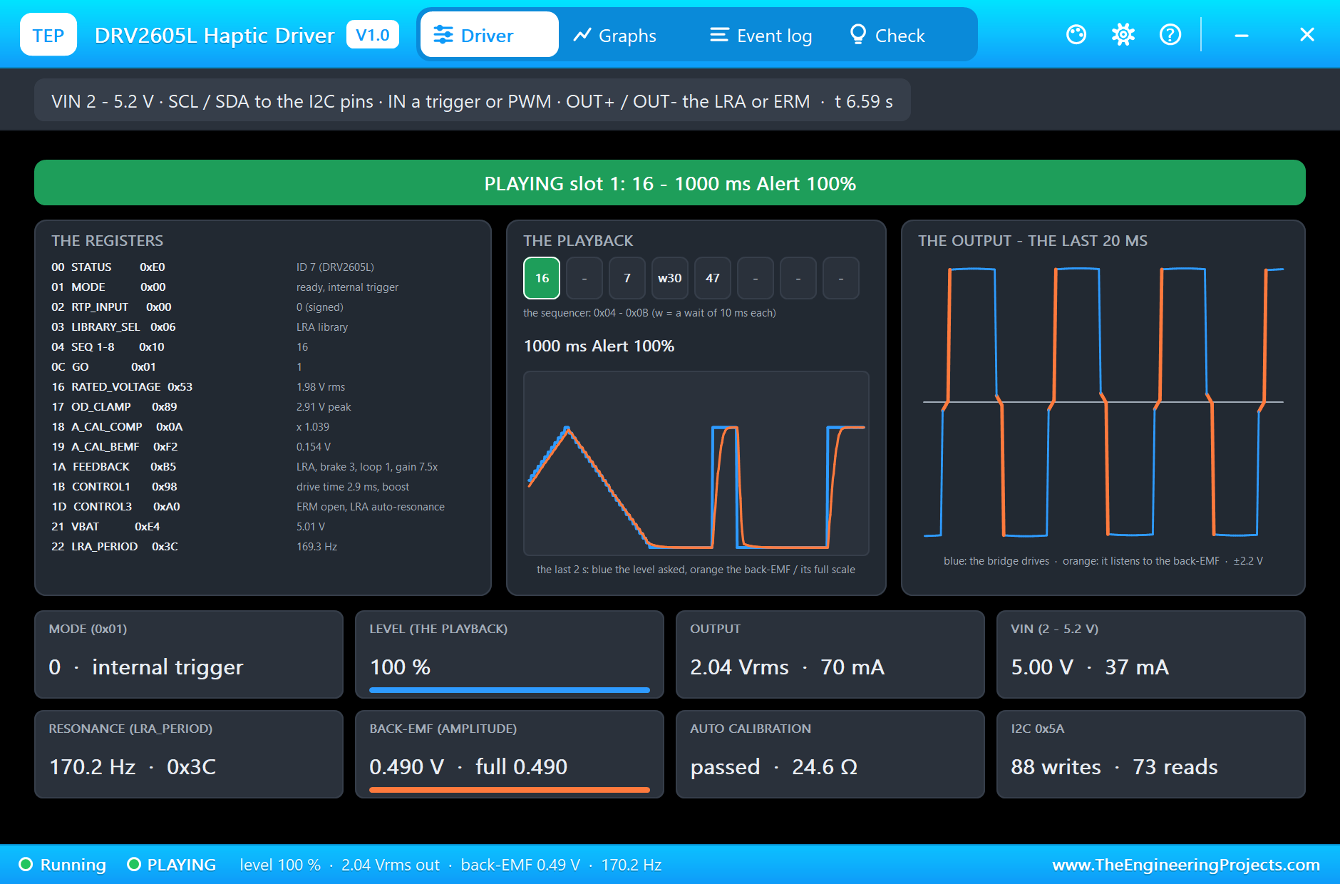
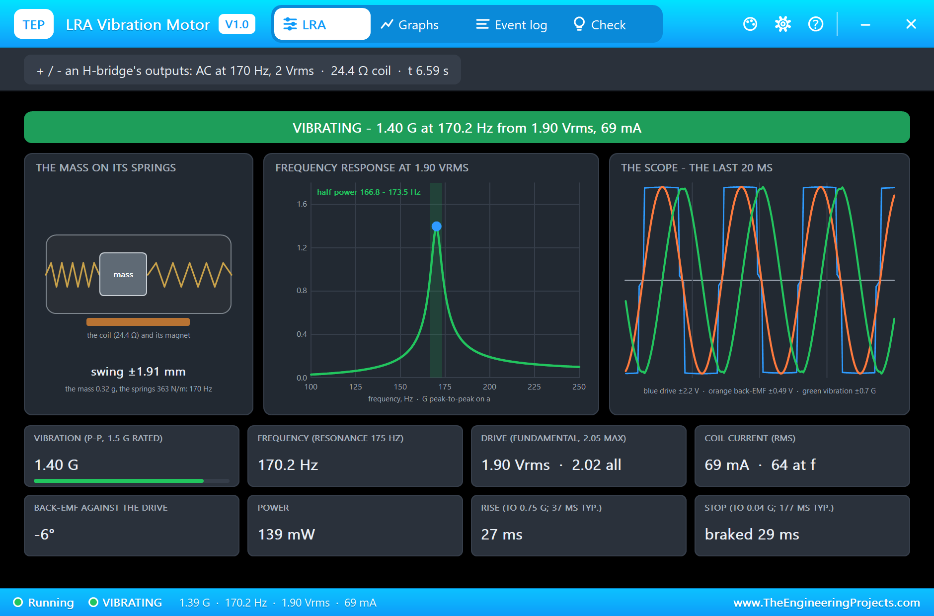
At 5.6 s the sketch starts effect 14, Strong Buzz, and clears GO after 150 ms: the Event log writes playback cancelled (GO cleared), and the loop brakes the LRA at once. At 6.3 s it plays effect 16, the 1000 ms Alert. After the overdrive the output settles at 2.04 Vrms, the rated voltage, with 70 mA in the LRA and the back-EMF at its full 0.489 V. The driver holds 170.1 Hz and the LRA shakes the 100 g mount at 1.40 G. The LRA's pop-up shows the same moment from the actuator's side.
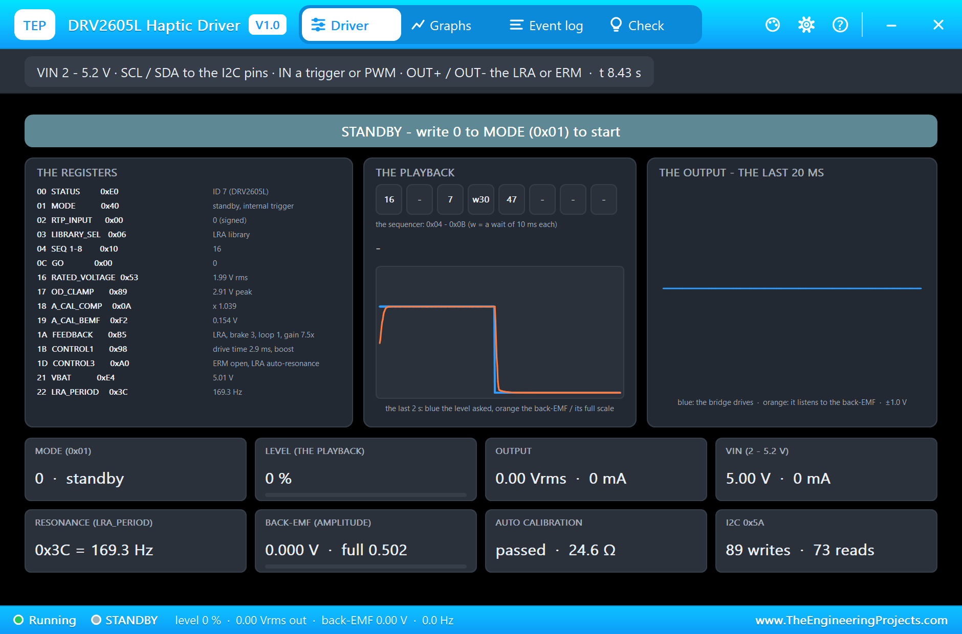
At 8 s the sketch writes 0x40 to MODE, and the chip goes back to standby with its outputs off.
The Graphs, the Event Log and the Check Page
The Graphs page plots the level, the output voltage, the back-EMF and the resonance over the last 2, 6 or 15 simulated seconds: every click shows as a short spike of output with the back-EMF rising and falling behind it. The Event log keeps every register change that matters, the calibration with its results, and every effect with its slot and name. The Check page sums up the supply, the I2C traffic, the mode, the actuator and its library, the voltages, the calibration and the resonance.
Try It Yourself
- Remove the calibration from the sketch: with the default A_CAL_BEMF the closed loop aims at the wrong back-EMF, and the vibration changes.
- Set the LRA's F0 to 166 or 180 Hz: the driver finds it, and LRA_PERIOD follows.
- Type
e 52(Pulsing Strong),e 58(Transition Click) ore 82(a ramp up): the effects by their names. - Set MODE to 1 and pulse D3: every rising edge on IN fires the sequence, and a second one cancels it.
- Set FB_BRAKE_FACTOR (0x1A bits 6 - 4) to 7, braking disabled, and compare the stop times in the LRA's pop-up.
Ideas to Extend the Demo
- Make a menu of effects on a few buttons, like a phone's keyboard taps.
- Use MODE 3 and a PWM pin on IN: the duty cycle sets the vibration.
- Drive our coin vibration motor (an ERM) instead: clear N_ERM_LRA and pick an ERM library.
Your Own Sketches
The demo sketch is in the zip file, and you can change it in the Arduino IDE. New to Arduino? Start with our Arduino Tutorial for Beginners. Export the compiled binary, and set the UNO's PROGRAM property to the new file. Our guide on How to get the HEX file from Arduino shows you where the file ends up.
Things to Know Before Using a Real DRV2605L
- Leave standby first: MODE powers up as 0x40; write 0x00 before anything plays.
- Calibrate for your actuator: write RATED_VOLTAGE and OD_CLAMP for it, then run the auto calibration once; you can store the results.
- Pick the right type and library: N_ERM_LRA = 1 and the LRA library for an LRA; the ERM libraries A to F suit ERMs of different start and stop times.
- Mind the clamp: the overdrive and the brake reach OD_CLAMP, so keep it within the motor's rating.
Troubleshooting
- Nothing plays: the chip is in standby (MODE 0x40), or LIBRARY_SEL is 0, the empty library.
- AUTO CALIBRATION FAILED: no actuator, the wrong type in N_ERM_LRA, or a load under 4 ohm.
- Weak or uneven vibration in closed loop: the calibration was not run, or RATED_VOLTAGE is too low for the actuator.
- LRA_PERIOD reads 0 or an odd value: it is only measured while the LRA plays, not while it is idle or braking.
- The part is not simulated:
TEPDRV2605.DLLis missing from MODELS and from the project folder.
Limitations of the Simulation
- The ROM effects are licensed and their waveforms are not published, so each effect is played from its name and strength; the closed loop adds the overdrive and the brake.
- Audio-to-vibe, the analog input mode, the OTP memory and over-temperature are not modelled; the output is averaged, without its PWM ripple.
- The output bridge is taken as 1 ohm, our figure, because the datasheet gives none.
- Arduino is a name of Arduino; this library is not made or endorsed by Arduino, Labcenter, Texas Instruments or any board maker.
- Tested in Proteus 8.5 in November 2026 (the demo as shipped). Proteus 7 is not supported.
So, that was all about the DRV2605L Haptic Driver Library for Proteus Simulation. I hope it helps you add haptics to your projects in a simulation first: a few register writes, a calibration, and a driver that finds the LRA's resonance on its own, plays its effects and brakes every one, with a pop-up that shows each register and every push and listen. If you have any questions, ask in the comments and I will help you out. Till the next tutorial, take care and have fun!

Comments
0