


M5Stack Core2 Library for Proteus: ESP32 TFT LCD Touch Screen


Hello friends, I hope you all are doing great. Today, I am going to share the M5Stack Core2 Library for Proteus. The Core2 is a finished little computer in a neat dark case: an ESP32, Wi-Fi, a sharp 2.0 inch colour TFT LCD and a capacitive touch screen, the same kind of glass as a phone. There are three touch dots under the screen, and a red Grove socket for sensors. With this library it runs your ESP32 Arduino sketch in Proteus 8.5, with the display and the touch working on the part.
M5Stack Core2 Library for Proteus
Latest version: V1.0 (November 2026, this tutorial)
Helping Tools
- Laptop WiFi Monitor: a laptop on the Wi-Fi of your design: a browser, a TCP / UDP terminal and ping
- Mobile WiFi Monitor: a smartphone that opens the pages of your board and sends it commands
- Serial Monitor Advance: a serial terminal window for the UART of your board
For the demo we built a pulse station. A finger rests on a MAX30102 sensor, and the Core2 draws the live pulse wave, with the heart rate and the oxygen level in big digits. The three dots switch between the pages, buttons on the glass set the alarm limit, and a phone on the same Wi-Fi reads the numbers. It looks like a small piece of hospital equipment, and it takes only a few pages of Arduino code.
NOTICE: Proteus has no ESP32 model, so our team has put a lot of effort into building this board ourselves: the Core2's pins, display, touch screen and Wi-Fi are all our own model, and your sketch compiles with our free TEP Boards for Proteus add-on. Your feedback is the fuel that keeps us going, so please tell us what you think in the comments below or in the M5Stack Core2 board of our forum. And if our free libraries help you, you can buy us a coffee. So, let's get started with the M5Stack Core2 Library for Proteus:
What is the M5Stack Core2?
The Core2 is the second generation of M5Stack's square development kits, 54 mm on a side. Inside is an ESP32-D0WDQ6-V3, with two 240 MHz cores, Wi-Fi, Bluetooth, 16 MB of flash and 8 MB of PSRAM. The front is a 2.0 inch 320 x 240 IPS screen with an ILI9342 controller, under an FT6336U capacitive touch panel. The case also holds an AXP192 power chip, a 500 mAh battery, an MPU6886 motion sensor, a BM8563 clock, a speaker, a microphone, a vibration motor and a TF card slot.
| Core2 | AtomS3 | Cheap Yellow Display | |
|---|---|---|---|
| Size | 54 x 54 x 16.5 mm | 24 x 24 x 13 mm | 86 x 50 mm |
| Display | 2.0 inch, 320 x 240 | 0.85 inch, 128 x 128 | 2.8 inch, 320 x 240 |
| Touch | capacitive | a key under the screen | resistive |
| Case and battery | yes | case only | bare board |
| Best for | finished products | tiny gadgets | wall panels |
Capacitive or Resistive?
A resistive screen, like the one on our Cheap Yellow Display, feels pressure: two films touch when you press. A capacitive screen feels your finger. The glass carries a grid of clear conductors, and a finger close to the grid changes the small capacitance at that spot. The FT6336U scans the grid many times a second and works out where the change is. That is why a light touch is enough, and why a glove or a plastic pen does nothing. The chip does all the work and gives the sketch finished coordinates over I2C, so there is no calibration and no ADC to read.
Three Dots That Are Not Buttons
The three dots under the screen look like buttons, but they are just printed marks. The touch panel is larger than the display, and it carries on below the bottom of the picture. A touch on the screen reports Y from 0 to 239, and a touch on a dot reports 240 or more. So one chip gives you a touch screen and three extra keys, with no moving parts at all. If you like tiny gadgets, our M5Stack AtomS3 Library for Proteus uses another clever idea: its whole screen is one key, and our M5StickC PLUS2 Library for Proteus is the one to wear.
Features of the M5Stack Core2 Library for Proteus
- The Core2 as it looks: the dark case, the black front with the screen, the three dots, the red PORT.A socket, the power key, USB-C and the RST key, with our small TEP signature.
- Your sketch: a .hex for "M5Stack Core2 (TEP Proteus)" with the real GPIO numbers - analogRead 0 to 4095, analogWrite and ledc PWM, attachInterrupt, tone, Serial, Serial2, Wire and SPI.
- The display on the part: Adafruit's ILI9341 library on the ILI9342 glass, 320 x 240 pixels in full colour.
- A touch screen you can click: click the glass or a dot with the mouse, and your sketch reads the place from the FT6336U on Wire1.
- Two I2C buses: Wire is PORT.A for your sensors, and Wire1 is the inside bus for the touch and the AXP192.
- Wi-Fi: WebServer and HTTPClient in station mode, with our phone and laptop windows on the same network.
- A complete package: about 3.8 MB with the part, the add-on, the MAX30102 and Wi-Fi monitor libraries and the demo, without the source code of the models.
The M5Stack Core2 in Proteus
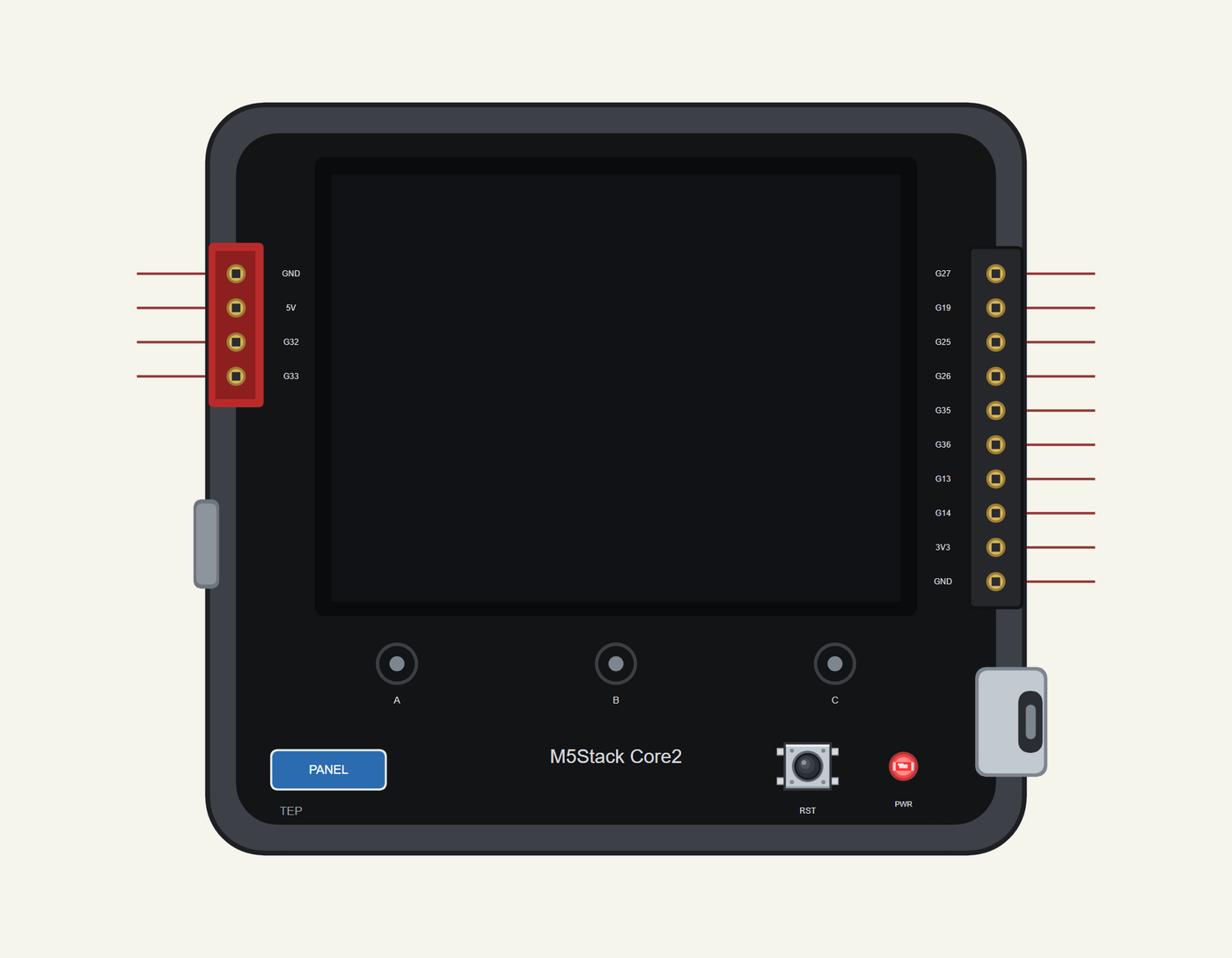
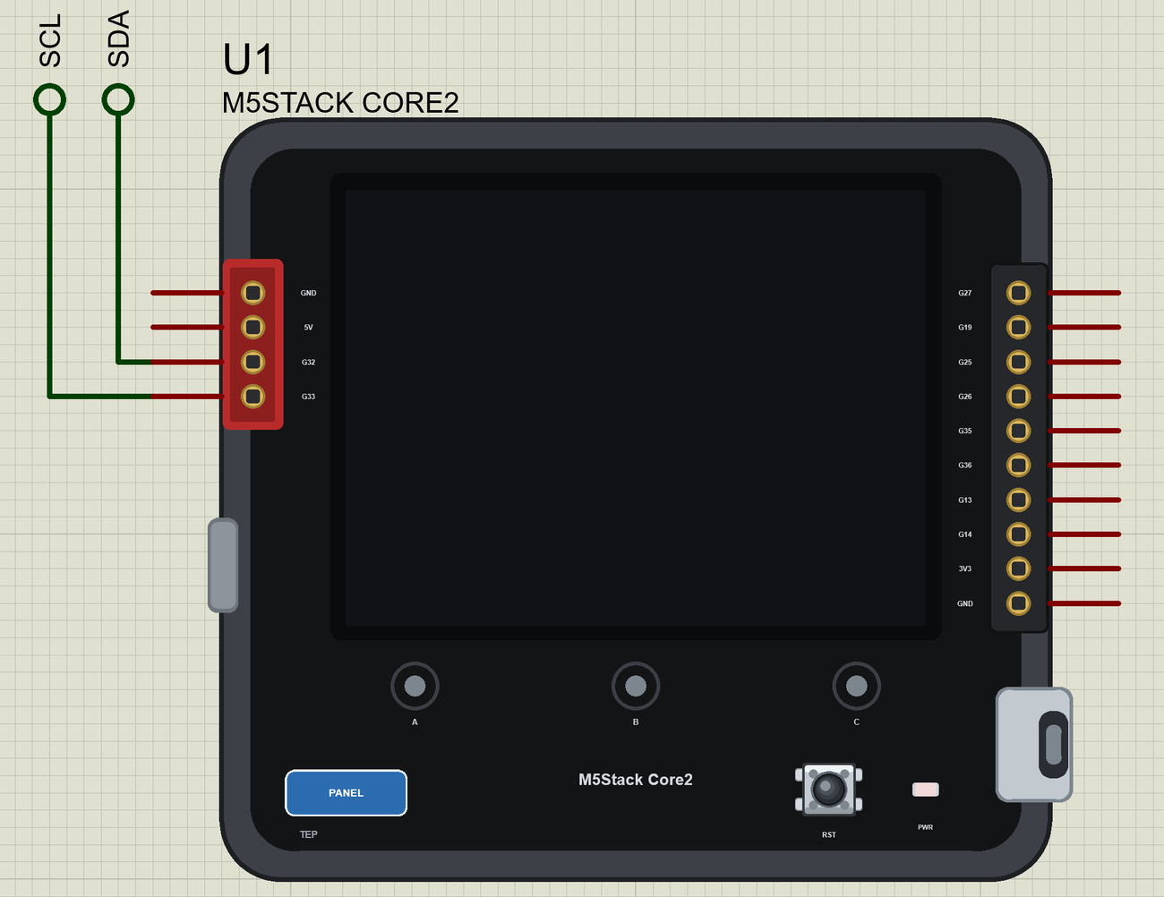
Search CORE2 in Pick Devices; the device is in TEPCORE2.LIB (Microprocessor ICs, ESP32 Boards), with the prefix U. It has two windows: click the USB-C port for the serial monitor, and the blue PANEL pad for the panel. A click on the glass does not open anything, because the glass is the touch screen. On the real product the M-BUS is a long connector at the back; we drew ten of its pins on the right, so that you can wire them.
The Pins
| Place | Pins | What the library does with them |
|---|---|---|
| PORT.A | G32, G33 | Wire SDA and SCL, or GPIO |
| PORT.A | 5V, GND | the supply |
| M-BUS | G27, G19, G25, G26 | GPIO, PWM, interrupt, and analogRead on three of them |
| M-BUS | G35, G36 | input only, analogRead |
| M-BUS | G13, G14 | Serial2 RX and TX, or GPIO |
| Inside | 23, 38, 18, 5, 15 | the display |
| Inside | 39 | the touch's INT, LOW while a finger is down |
The variant gives the inside pins names, such as TOUCH_INT, TFT_CS and PORTA_SDA, so a sketch reads clearly. The motion sensor, the clock, the speaker, the microphone, the vibration motor and the TF card are not modelled. Note that M5Stack's own M5Core2 and M5Unified libraries are not for this part: use the pins directly, as our demo does.
Download M5Stack Core2 Library for Proteus
Click the button below to download M5Stack-Core2-Library-for-Proteus-v1.0.zip (about 3.8 MB, without the source code of the models):
M5Stack Core2 Library for Proteus V1.0- README.txt: installation, the demo, the pins, the touch, the properties, troubleshooting and the limits.
- Proteus Library Files:
TEPCORE2.LIBand the demo's parts:TEPMAX30102.LIB,TEPMOBILE.LIBandTEPLAPTOP.LIB. - Proteus Model Files:
TEPNET.DLLandTEPMAX30102.DLL. - Arduino Code: the demo sketch and the TEP Boards for Proteus add-on 1.52.0.
- Proteus Simulation: the demo project, its HEX file and copies of the DLLs.
No Proteus yet? Read How to Download and Install Proteus 7 and 8. New to libraries? Follow How to Install a New Library in Proteus.
How to Install M5Stack Core2 Library for Proteus
- Close Proteus and extract the whole zip file, for example to your Desktop.
- Copy the files from Proteus Library Files into the LIBRARY folder of Proteus.
- Copy the DLLs from Proteus Model Files into the MODELS folder, replacing an older TEPNET.DLL.
- Delete
TEPCORE2.IDXfrom the LIBRARY folder if it is there. - For your own sketches, copy Arduino Code\TEP Boards for Proteus\hardware into your Arduino sketchbook (Documents\Arduino) and restart the Arduino IDE; the board is M5Stack Core2 (TEP Proteus). Install Adafruit ILI9341, Adafruit GFX, Adafruit BusIO and the SparkFun MAX3010x library from the Library Manager.
- Start Proteus, press P and search for CORE2.
Demo: a Pulse Station
A fingertip pulse oximeter is one of the most common medical gadgets in the world. It clips on your finger and, within seconds, shows your heart rate and how much oxygen your blood is carrying. Inside there is no needle and no chemistry, only two small LEDs and a light sensor. That makes it a wonderful project for learning, because a little code can turn a stream of raw numbers into something you can see. This is a demonstration, though, and not a medical instrument, so please do not use it for health decisions.
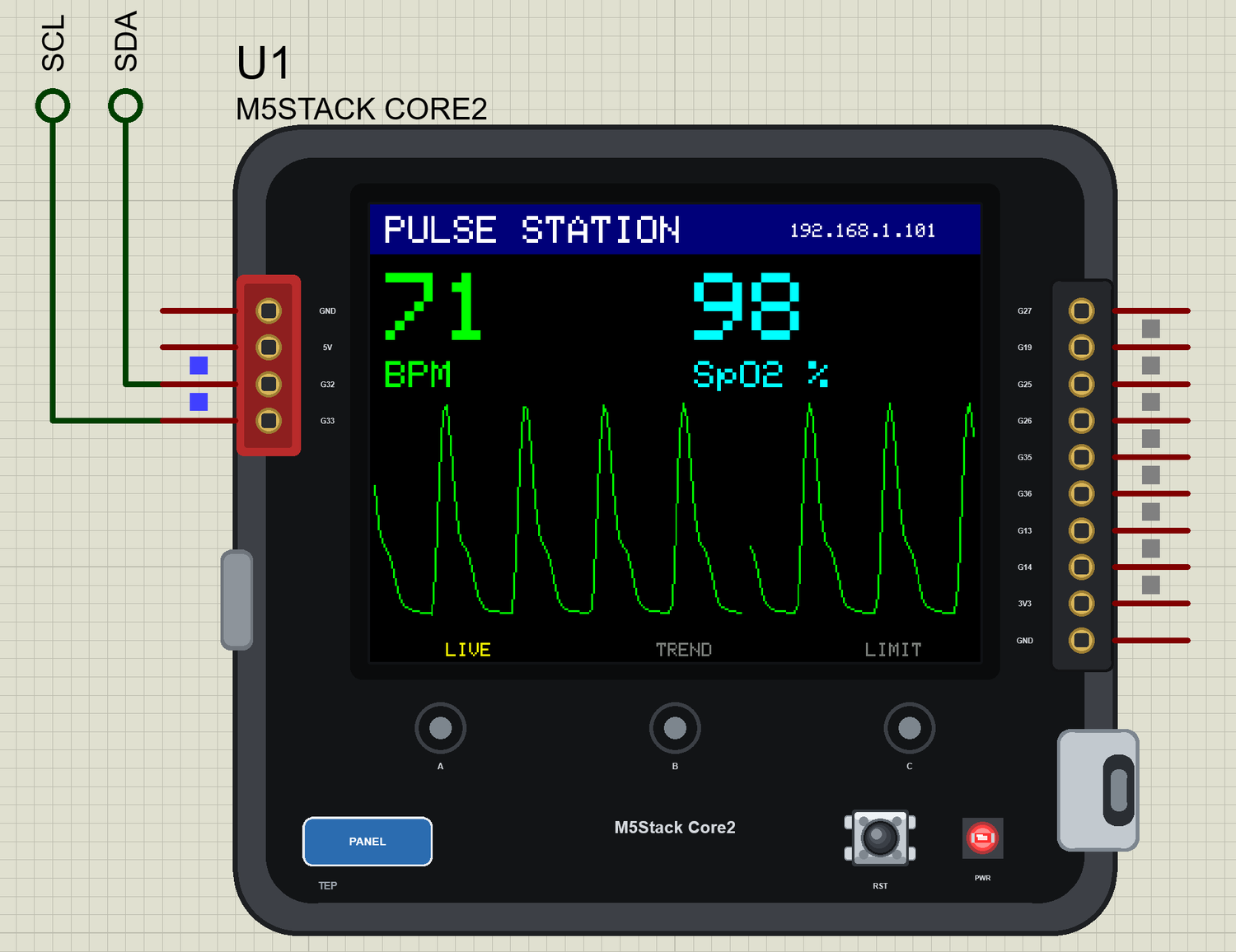
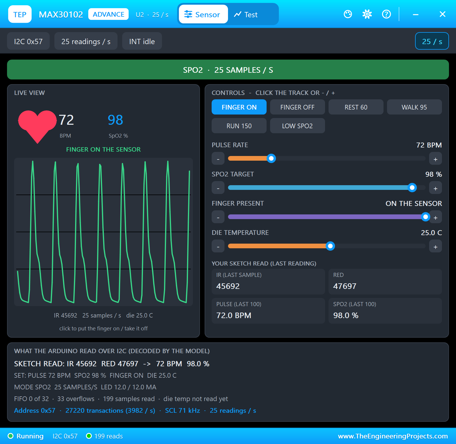
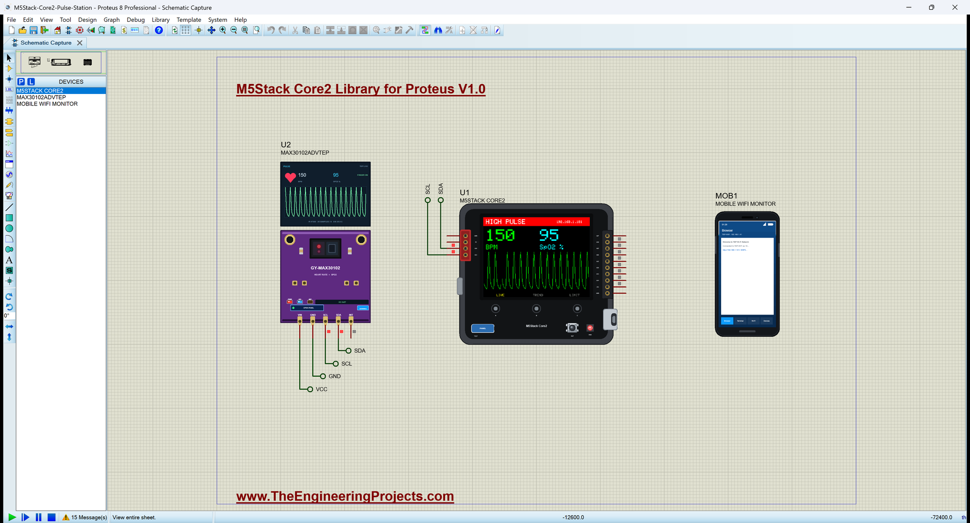
Open M5Stack-Core2-Pulse-Station.pdsprj. U1 runs Core2_Pulse_Station.hex. U2 is the sensor from our MAX30102 Library for Proteus, in the Advance version, on PORT.A. MOB1 is our Mobile WiFi Monitor, and the monitor is the same window as our TEP Serial Monitor Advance for Proteus.
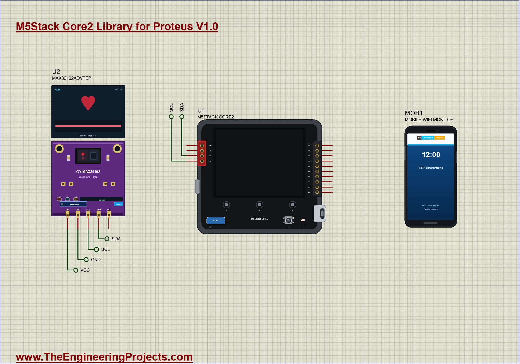
| Module pin | Net label | Core2 pin | What it does |
|---|---|---|---|
| MAX30102 SDA | SDA | G32 | I2C data, address 0x57 |
| MAX30102 SCL | SCL | G33 | I2C clock |
| MAX30102 VIN, GND | VCC, GND | - | the supply |
How a Pulse Oximeter Works
The MAX30102 shines a red LED and an infrared LED into your fingertip, and a photodiode measures the light that comes back. With every heartbeat, a little more blood pushes into the tiny vessels of the finger and takes more of the light. So the signal has a steady part, from the skin and bone, and a small ripple that beats with your heart. Count the ripples and you have the heart rate.
The oxygen level comes from a neat trick. Blood rich in oxygen is bright red: it lets red light through and absorbs more infrared. Blood short of oxygen does the opposite. So the sketch compares the size of the ripple in each colour. This ratio, called R, is turned into a percentage with a formula found by measuring real people. The result is called SpO2, and a healthy reading is 95 % or more.
Reading the Touch
The Core2 has two I2C buses, and each has its own job. Wire is PORT.A, for your sensors, and Wire1 is the inside bus. The FT6336U sits there, at address 0x38. Reading it is the usual I2C pattern: write the number of the first register, then ask for five bytes. Those are the number of touches, then X and Y, each split into two bytes. The sketch checks the INT pin first, so it leaves the bus alone while nobody is touching the screen:
bool readTouch(int &x, int &y) {
  if (digitalRead(TOUCH_INT) == HIGH) return false;         // INT is LOW while a finger is down
  Wire1.beginTransmission(TOUCH_ADDR);
  Wire1.write(0x02);                                        // the number of touches, then the first touch's X and Y
  Wire1.endTransmission();
  Wire1.requestFrom(TOUCH_ADDR, 5);
  const byte touches = Wire1.read() & 0x0F;
  const byte xh = Wire1.read(), xl = Wire1.read(), yh = Wire1.read(), yl = Wire1.read();
  x = ((xh & 0x0F) << 8) | xl;
  y = ((yh & 0x0F) << 8) | yl;
  return touches > 0;
}
Pages and Dots
Remember that a Y of 240 or more means one of the three dots. The sketch splits the width into three, which gives the three pages. It acts only when the finger first comes down, by comparing with the last pass. On the LIMIT page, the two big buttons on the glass change the limit. The touch code stays this short because the chip has done the hard part:
void handleTouch() {
  int x, y;
  const bool touched = readTouch(x, y);
  if (touched && !wasTouched) {
    Serial.print(F("Touch at ")); Serial.print(x); Serial.print(F(", ")); Serial.println(y);
    if (y >= 240) {                                         // the three dots under the screen
      page = x < 107 ? LIVE : x < 213 ? TREND : LIMIT;
      Serial.print(F(">> Page ")); Serial.println(page == LIVE ? F("LIVE") : page == TREND ? F("TREND") : F("LIMIT"));
      drawPage();
    } else if (page == LIMIT && y >= 150 && y < 216) {
      if (x < 140) changeLimit(-10);
      else if (x >= 180) changeLimit(10);
    }
  }
  wasTouched = touched;
}
Reading the Sensor
The MAX30102 keeps its samples in a small memory called a FIFO, so nothing is lost while the sketch is busy for a moment. SparkFun's library collects them with check(), and the loop takes them one by one. A very low reading means no finger, and the first time that happens the numbers are cleared. Each good sample goes straight to the plot, and to two arrays for the estimate:
void readSensor() {
  if (!sensorOk) return;
  sensor.check();
  while (sensor.available()) {
    const uint32_t ir = sensor.getFIFOIR(), r = sensor.getFIFORed();
    sensor.nextSample();
    const bool on = ir >= 5000 && r >= 5000;
    if (on != finger) {
      finger = on;
      used = 0;
      Serial.println(on ? F(">> Finger on the sensor") : F(">> No finger"));
      if (!on) { bpm = 0; oxygen = 0; setAlarm(false); }
      if (page == LIVE) drawNumbers();
    }
    if (!on || ir > 65535 || r > 65535) continue;
    plotSample(ir);
    infrared[used] = ir; red[used] = r;
    if (++used == WINDOW) { estimate(); used = 0; }
  }
}
Turning Samples into Numbers
Every 100 samples, which is four seconds, the sketch works out one estimate. It finds the highest and lowest values, then a line half way between them. Each time the signal crosses that line going up, that is one beat. The time between the first and last crossing gives the rate. The SpO2 uses the size of the ripple in each colour, divided by the average, and Maxim's formula. The window of four seconds is why the number changes a little after the finger does:
void estimate() {
  uint16_t irMin = 65535, irMax = 0, redMin = 65535, redMax = 0;
  uint32_t irSum = 0, redSum = 0;
  for (byte i = 0; i < WINDOW; i++) {
    irMin = min(irMin, infrared[i]); irMax = max(irMax, infrared[i]);
    redMin = min(redMin, red[i]); redMax = max(redMax, red[i]);
    irSum += infrared[i]; redSum += red[i];
  }
  plotMin = irMin; plotMax = irMax;
  if (irMax - irMin < 100 || redMax - redMin < 100) return;
  const uint16_t middle = irMin + (irMax - irMin) / 2;
  int first = -1, last = -1, beats = 0;
  for (byte i = 1; i < WINDOW; i++) {
    if (infrared[i - 1] < middle && infrared[i] >= middle) {
      if (first < 0) first = i;
      last = i;
      beats++;
    }
  }
  if (beats < 2) return;
  bpm = 60.0 * SAMPLES_PER_S * (beats - 1) / (last - first) + 0.5;
  const float ratio = ((float)(redMax - redMin) / redSum) / ((float)(irMax - irMin) / irSum);
  oxygen = constrain(-45.060 * ratio * ratio + 30.354 * ratio + 94.845 + 0.5, 0, 100);   // Maxim's approximation
  Serial.print(F("Pulse ")); Serial.print(bpm); Serial.print(F(" BPM  SpO2 ")); Serial.print(oxygen); Serial.println(F(" %"));
  if (trendCount == TREND_BARS) { memmove(trend, trend + 1, TREND_BARS - 1); trendCount--; }
  trend[trendCount++] = min(bpm, 255);
  setAlarm(bpm > highLimit || oxygen < LOW_OXYGEN);
  if (page == LIVE) drawNumbers();
  else if (page == TREND) drawTrend();
}
Drawing the Waveform
Each sample moves the plot two pixels to the right. A real-time graph has to erase what is ahead of it, so the sketch clears a thin strip in front of the line, like the moving gap on a heart monitor in a film. Here is a small surprise: each beat takes light away, so the raw signal dips at every heartbeat. That is why the Y calculation has no minus sign. Drawn this way up, the beats are peaks, which is how a medical monitor shows them:
void plotSample(uint16_t value) {                           // one step of the waveform, two pixels wide
  if (page != LIVE || plotMax <= plotMin) return;
  // each beat takes light away, so the raw signal dips: upside down, the beats are peaks
  const int y = PLOT_TOP + constrain((value - plotMin) * (PLOT_HEIGHT - 1) / (plotMax - plotMin), 0L, (long)PLOT_HEIGHT - 1);
  tft.fillRect(plotX + 1, PLOT_TOP, 6, PLOT_HEIGHT, ILI9341_BLACK);
  if (plotY >= 0) tft.drawLine(plotX, plotY, plotX + 2, y, ILI9341_GREEN);
  plotY = y;
  plotX += 2;
  if (plotX >= 316) { plotX = 0; plotY = -1; }
}
The Alarm
The alarm follows the same rule as every good alarm: act only on a change. setAlarm() does nothing if the state is already right, so the monitor gets one clear line and the band is drawn once. The two limits are a pulse above the value that you set, and an oxygen level under 92 %:
void setAlarm(bool on) {
  if (on == alarmOn) return;
  alarmOn = on;
  if (on) {
    if (oxygen < LOW_OXYGEN) { Serial.print(F(">> LOW OXYGEN: ")); Serial.print(oxygen); Serial.println(F(" %")); }
    else { Serial.print(F(">> HIGH PULSE: ")); Serial.print(bpm); Serial.println(F(" BPM")); }
  } else Serial.println(F(">> Back to normal"));
  drawBand();
}
Starting Up
The display and the sensor start first, and Wi-Fi comes last, because WiFi.begin() takes a moment. sensor.setup() sets the LED brightness, the averaging, the mode with both LEDs, the sample rate and the range. Note the two begin() calls: one for each bus. On a real Core2 there is one more job, which the AXP192 handles: it must switch on the display's power and backlight, and M5Unified does that for you:
void setup() {
  Serial.begin(115200);
  Serial.println(F("Core2 Pulse Station - The Engineering Projects"));
  pinMode(TOUCH_INT, INPUT);
  SPI.begin(TFT_SCLK, TFT_MISO, TFT_MOSI, TFT_CS);
  tft.begin();
  tft.setRotation(1);
  tft.fillScreen(ILI9341_BLACK);
  Wire.begin(PORTA_SDA, PORTA_SCL);                         // PORT.A: the sensor
  Wire1.begin(INT_SDA, INT_SCL);                            // the inside bus: the touch
  sensorOk = sensor.begin(Wire, I2C_SPEED_STANDARD);
  if (sensorOk) sensor.setup(60, 4, 2, 100, 411, 4096);
  else Serial.println(F("MAX30102 not found: check PORT.A"));
  WiFi.begin(WIFI_NAME, WIFI_PASS);
  while (WiFi.status() != WL_CONNECTED) delay(100);
  Serial.print(F("Wi-Fi: http://")); Serial.print(WiFi.localIP()); Serial.println(F("/"));
  server.on("/", handleRoot);
  server.on("/more", []() { changeLimit(10); handleRoot(); });
  server.on("/less", []() { changeLimit(-10); handleRoot(); });
  server.begin();
  drawPage();
}
The Page for the Phone
WebServer calls a function for each address, and that function builds the page as a String. The links /more and /less use the same changeLimit() as the buttons on the glass, so the screen and the phone always agree:
void handleRoot() {
  String h = F("<html><body><h2>Pulse Station</h2><p>");
  if (finger && bpm) { h += bpm; h += F(" BPM, SpO2 "); h += oxygen; h += F(" %"); }
  else h += F("No reading yet");
  h += F("</p><p>");
  h += alarmOn ? F("ALARM") : F("Normal");
  h += F(", limit ");
  h += highLimit;
  h += F(" BPM</p><p><a href='/more'>LIMIT +10</a></p><p><a href='/less'>LIMIT -10</a></p></body></html>");
  server.send(200, "text/html", h);
}
Keeping the Loop Quick
Three small jobs share loop(): the web server, the touch and the sensor. None of them waits, and for a good reason. SparkFun's library keeps only the newest four samples, which is 160 ms at 25 samples a second. Our first version drew a whole page in that time, lost a few samples, and reported a false 170 BPM, because the beats looked closer together than they were. So a full page now starts a new window, and the limit button redraws only its number. The waveform touches a thin strip at a time, so the screen never flickers.
Run the Demo
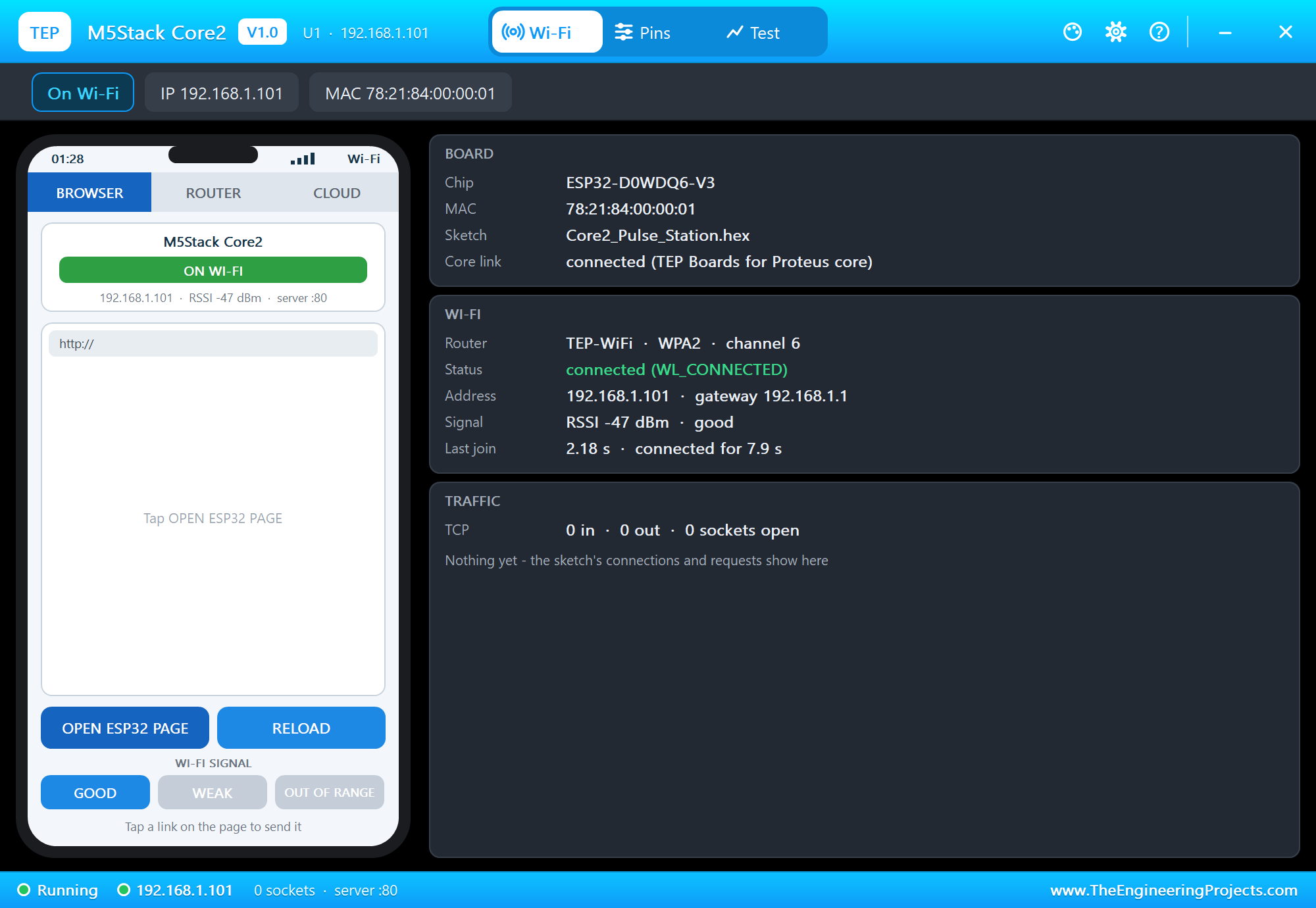
Press Run. The Core2 joins the Wi-Fi network, and the sensor starts with a finger already on it. The waveform crawls across the screen, and every four seconds the monitor prints an estimate:
Core2 Pulse Station - The Engineering Projects
Wi-Fi: http://192.168.1.101/
>> Finger on the sensor
Pulse 71 BPM  SpO2 98 %
Pulse 71 BPM  SpO2 98 %
Pulse 72 BPM  SpO2 98 %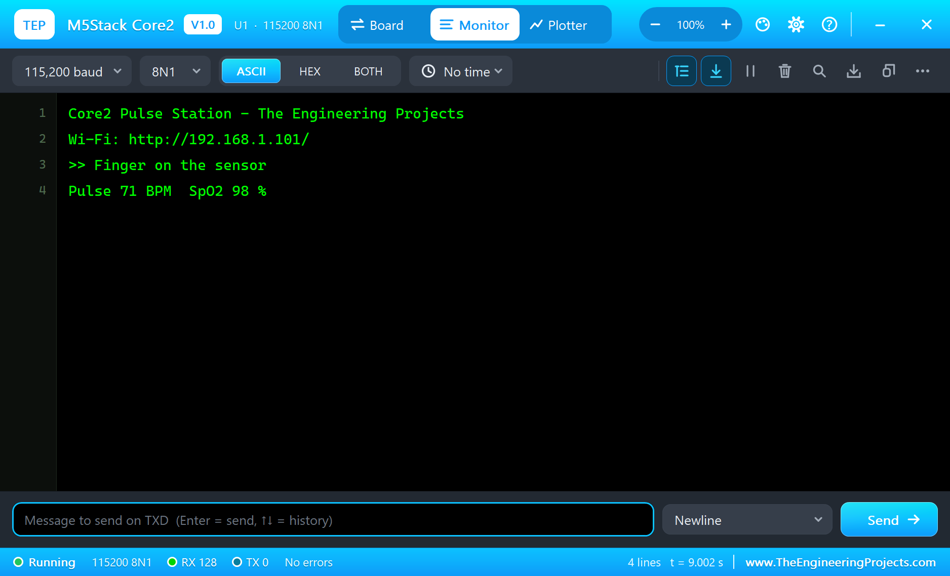
A High Pulse
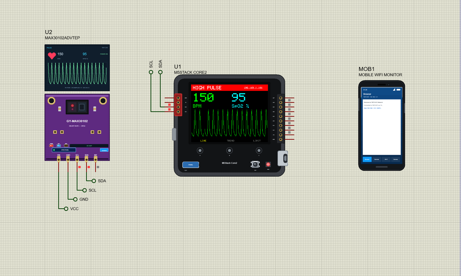
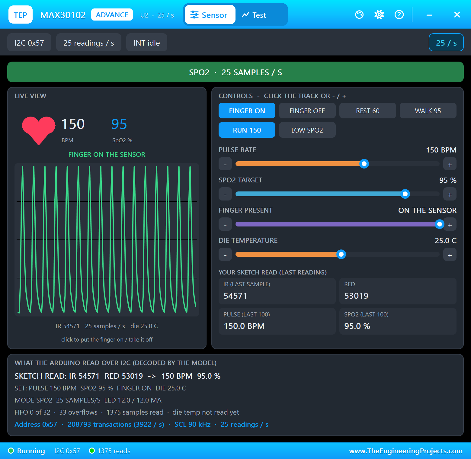
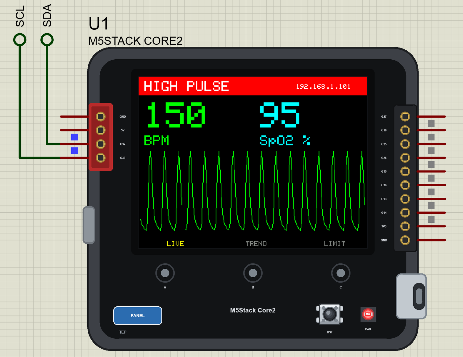
Click RUN 150 on the sensor's window. The waveform speeds up, and when the estimate passes the limit of 120 BPM, a red band says HIGH PULSE:
Touch the Screen
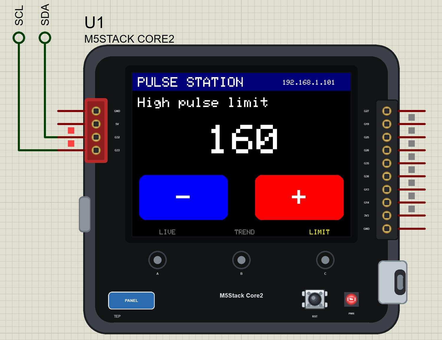
Now click the dot C with the mouse, for the LIMIT page, and click the red + button on the glass four times. As soon as the limit reaches the pulse, the band goes back to blue. We stop at 160, to leave a little room:
Low Oxygen
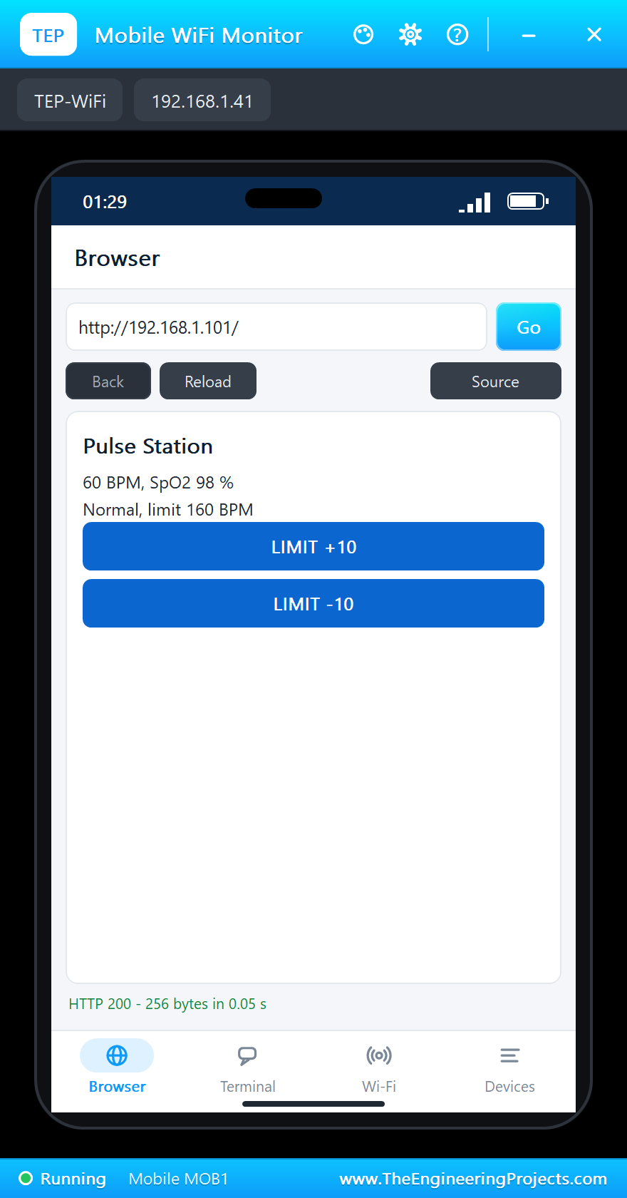
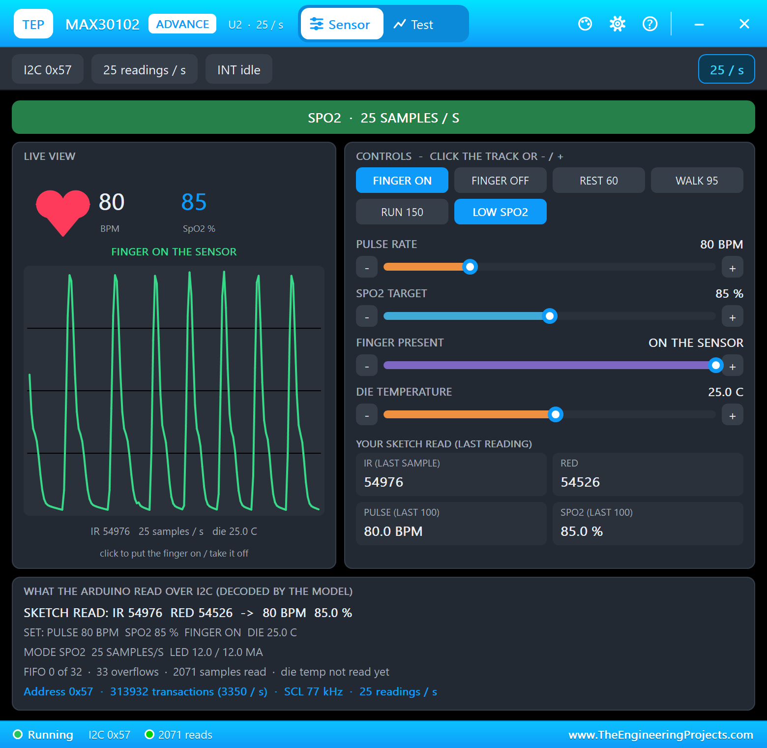
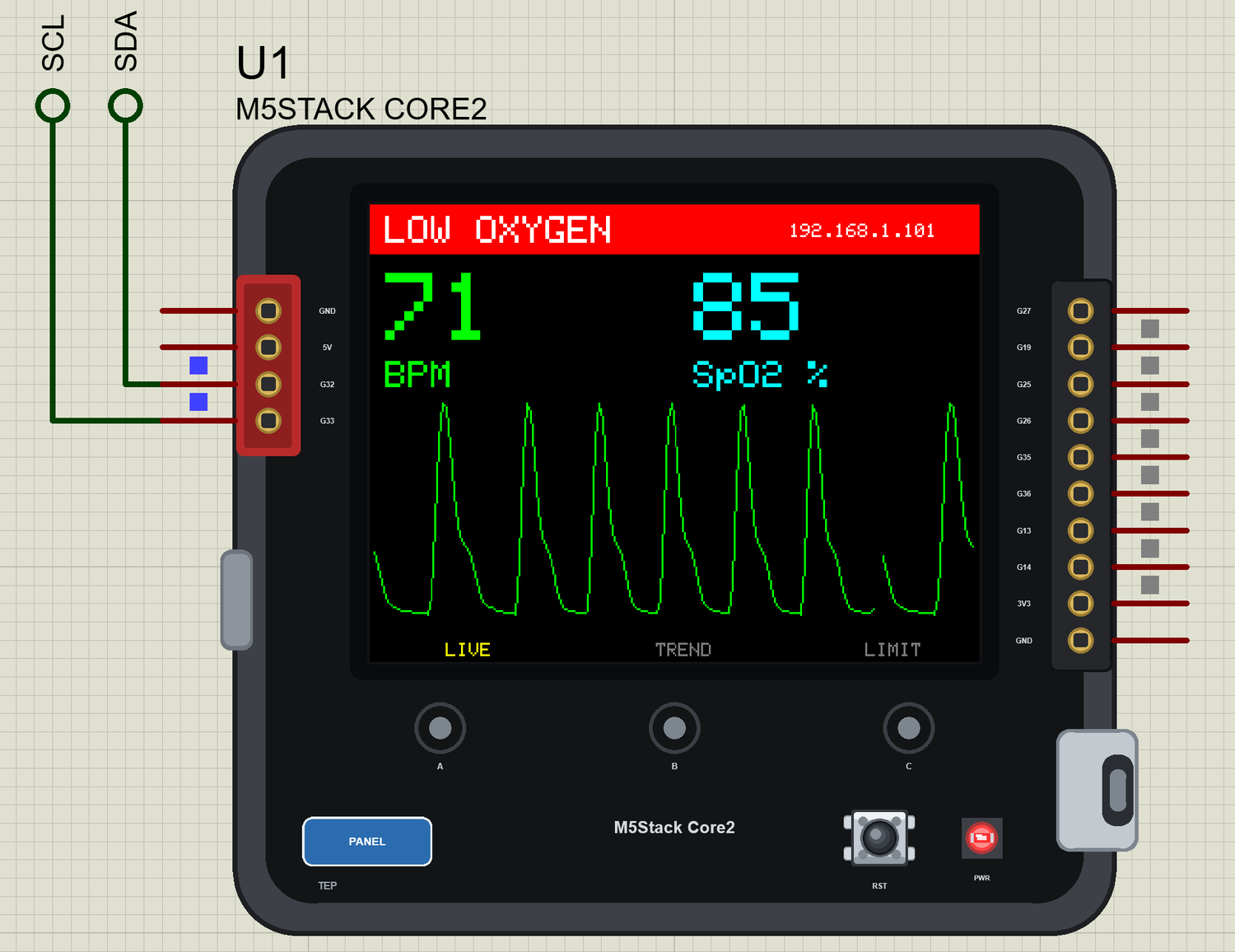
Click the dot A, then REST 60, and the pulse settles down. Now click ESP32 U1 on the phone for the page. Then click LOW SPO2 on the sensor: the oxygen level falls below 92 %, and the band says LOW OXYGEN:
The Trend
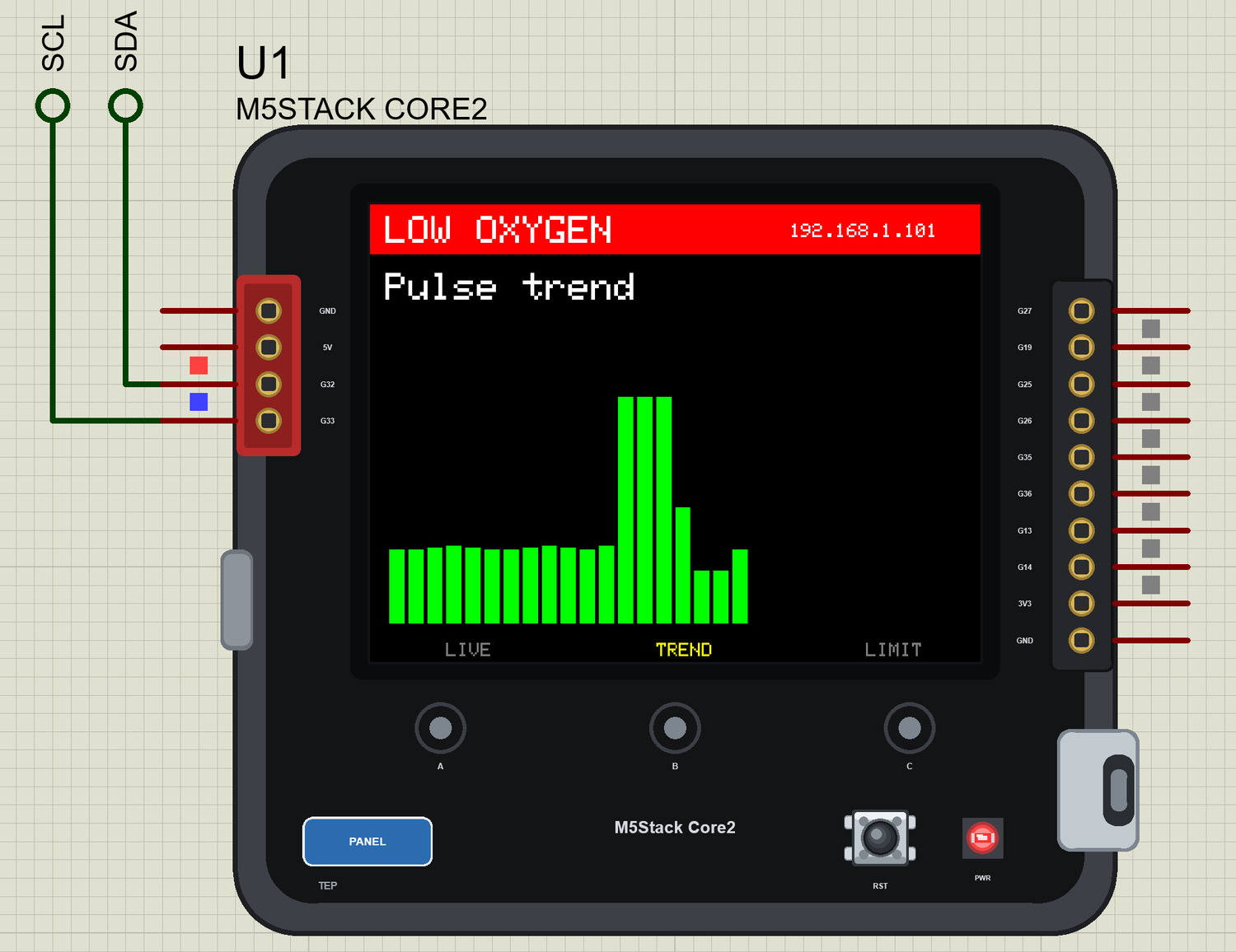
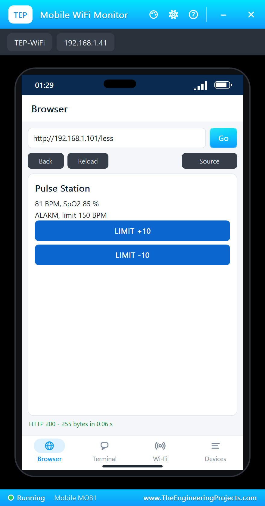
Click the dot B. The TREND page shows the last estimates as bars, and a bar above the limit turns red, so you can see the whole session at a glance. On the phone, tap LIMIT -10, and the limit falls to 150 on both screens. Finally click FINGER OFF, and the numbers clear:
The built-in serial monitor has followed everything:
Pulse 150 BPM  SpO2 95 %
>> HIGH PULSE: 150 BPM
Touch at 283, 275
>> Page LIMIT
Touch at 245, 183
>> High pulse limit 130 BPM
Touch at 245, 183
>> High pulse limit 140 BPM
Touch at 245, 183
>> High pulse limit 150 BPM
>> Back to normal
Pulse 150 BPM  SpO2 95 %
Touch at 245, 183
>> High pulse limit 160 BPM
Touch at 37, 275
>> Page LIVE
Pulse 60 BPM  SpO2 98 %
Pulse 71 BPM  SpO2 85 %
>> LOW OXYGEN: 85 %
Touch at 160, 275
>> Page TREND
Pulse 81 BPM  SpO2 85 %
>> High pulse limit 150 BPM
>> No finger
>> Back to normal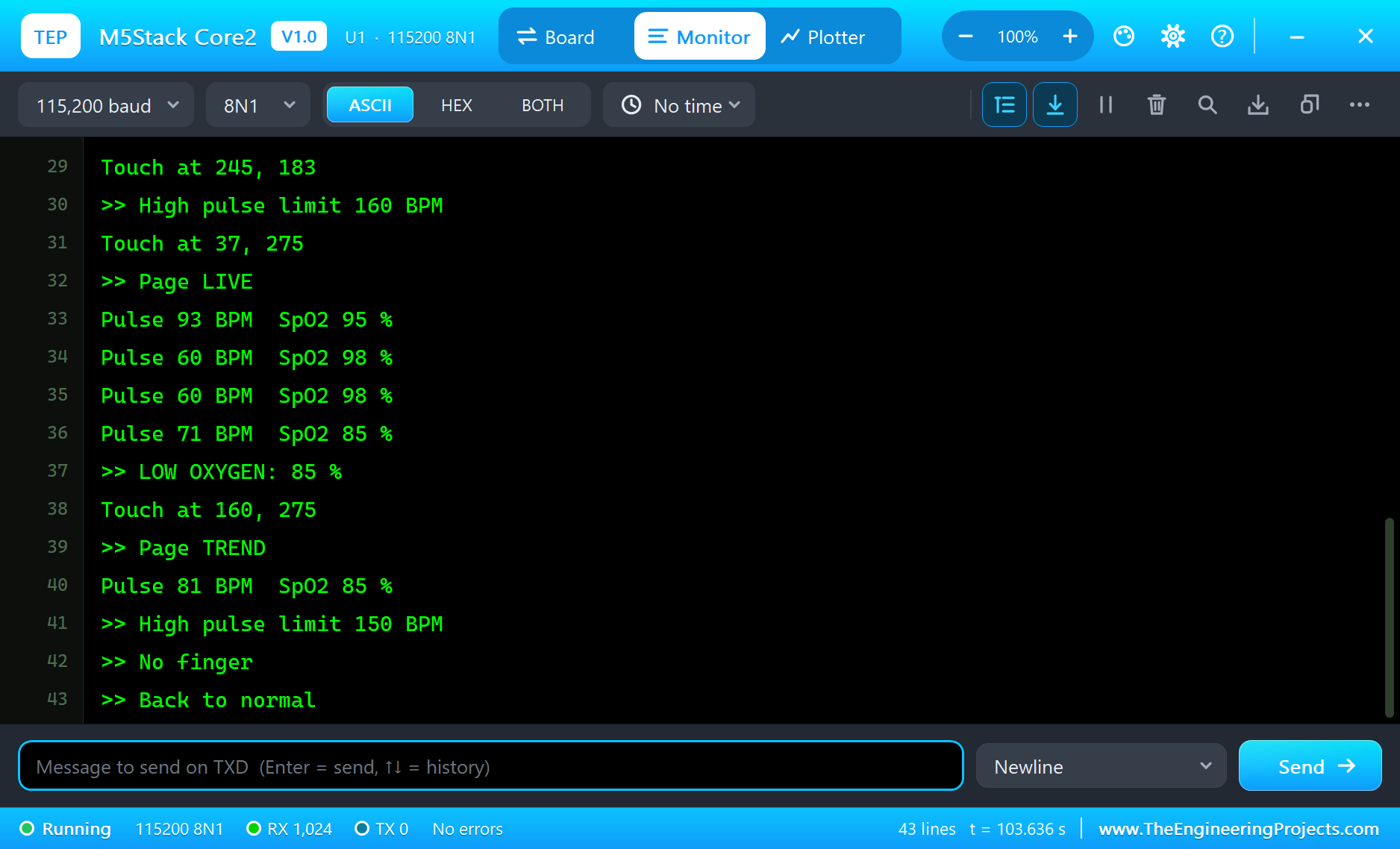
Try It Yourself
- Click WALK 95 and watch the estimate follow within two windows.
- Move the PULSE RATE slider and find the point where the alarm starts.
- Change
LOW_OXYGENand rebuild the sketch. - Draw the red signal on the plot too, in a second colour.
Ideas to Extend the Pulse Station
- Log a session to a web service, and draw a chart of the whole week.
- Calculate the average, lowest and highest pulse of a session.
- Add a low pulse limit beside the high one.
- Use the Core2 as a training timer, with zones for easy, steady and hard.
Your Own Sketches
Write the sketch in the Arduino IDE with the board M5Stack Core2 (TEP Proteus), use Sketch > Export Compiled Binary and set the part's PROGRAM property to the .hex. The pin names are in the variant, so your sketch stays short. The touch functions of this demo can be copied as they are. On a real Core2 use the same pins with Espressif's "esp32" package, and let M5Unified start the AXP192.
Things to Know Before Using a Real Core2
- The AXP192 comes first: it powers the display and the backlight, so nothing shows until it is set up. M5Unified does this for you.
- Two batches of display: M5Stack has changed the glass from ILI9342C to ILI9342E on newer units, and that needs a recent M5GFX.
- Keep the finger still: a real sensor picks up every small movement as a false beat, so rest your hand and press lightly.
- Ambient light matters: a real MAX30102 needs a shade around the finger in a bright room.
- It is not a medical device: use a certified oximeter for anything to do with health.
Properties of the M5Stack Core2
| Property | What it does |
|---|---|
| PROGRAM | the sketch: a .hex from TEP Boards for Proteus (board "M5Stack Core2") |
| WIFISSID, WIFIPASS | the router in range (TEP-WiFi, 12345678) |
| MONITOR, BAUD, AUTOOPEN | the built-in serial monitor: on, its baud rate (115200), open at Run |
Troubleshooting
- The display stays black: call
SPI.begin(TFT_SCLK, TFT_MISO, TFT_MOSI, TFT_CS)andtft.begin(). - The picture is upside down: use
tft.setRotation(1). - The touch does nothing: set
TOUCH_INTas an input and callWire1.begin(INT_SDA, INT_SCL). - The MAX30102 is not found: it is on PORT.A, so call
Wire.begin(PORTA_SDA, PORTA_SCL). - The numbers never appear: an estimate needs four seconds of samples with a finger on the sensor.
- The phone shows the Welcome page: click ESP32 U1 in its list of devices.
- A number goes wrong above 32767: int is 16 bits in the simulation - use long.
Limitations of the Simulation
- Your sketch gets 8 KB of RAM in the simulation, and there are no FreeRTOS tasks and no second core. A heavy graphics library such as LVGL does not fit.
- The MPU6886, the BM8563, the speaker, the microphone, the vibration motor, the TF card and Bluetooth are not modelled. The AXP192 is only a set of registers here.
- A click holds the finger down for a moment, so hold the mouse button for a long press. Dragging on the glass is not followed.
- M5Core2 and M5Unified do not run on this part: use the pins directly.
- M5Stack and Core2 are names of M5Stack and ESP32 of Espressif Systems; this library is not made or endorsed by them or by Labcenter.
- Tested in Proteus 8.5 in October 2026 (the demo as shipped, about 105 s of simulation). Proteus 7 is not supported.
So, that was all about the M5Stack Core2 Library for Proteus. I hope it helps you design your own touch screen products before you buy one - the display, the capacitive touch, the three dots, PORT.A and Wi-Fi in one simulation. If you have any questions, ask in the comments and I will help you out. Till the next tutorial, take care and have fun!

Comments
0