


Project Files of M5Stack Core2 Library for Proteus: ESP32 TFT LCD Touch Screen
 Libraries
 Code
 Projects
 Simulation
m5stack-core2-tep-v1-0-a9cc462301d240808e032b4086b41335.zip
M5Stack Core2 Library for Proteus V1.0
M5Stack Core2 Library for Proteus V1.0 comes as a ZIP archive of 241 files (3.6 MB, 8.0 MB unpacked) holding Proteus library files, simulation model DLLs, a Proteus simulation, an Arduino sketch, an Arduino library, compiled HEX firmware and source code.
- LIBProteus library
- DLLProteus model
- DSNProteus simulation
- INOArduino sketch
- LIBArduino library
- HEXHEX firmware
- SRCSource code
Description
M5Stack-Core2-Library-for-Proteus-v1.0.zip with the M5Stack Core2 in Proteus (your ESP32 sketch with the real GPIO numbers, the 2.0 inch display, the capacitive touch and its three dots, PORT.A, the M-BUS pins, the panel and a serial monitor; TEPCORE2.LIB, TEPNET.DLL and the TEP Boards for Proteus add-on 1.52.0), the MAX30102 and Wi-Fi monitor libraries, the pulse station demo with its sketch and a README.

File Structure
 File Structure
10.7 KB1.1 KB7.7 KB11 KB8.5 KB1.5 KB1.7 KB1.9 KB5.7 KB4.9 KB1.1 KB5.8 KB9.6 KB7.2 KB2.5 KB2.1 KB1.9 KB2.1 KB4.4 KB1.1 KB3 KB3 KB1.8 KB2.5 KB3.5 KB149 B2.7 KB2 KB6.4 KB3.2 KB1.3 KB963 B8.6 KB5.9 KB6 KB11.3 KB1.6 KB1.3 KB14.7 KB4.3 KB6.1 KB20.1 KB8.2 KB2 KB4.5 KB311 B12.8 KB6.7 KB6.1 KB2.2 KB3.4 KB5.9 KB1.5 KB1.6 KB16.6 KB9.7 KB6.9 KB2.1 KB533 B3.6 KB3.8 KB504 B8.3 KB10.9 KB522 B918 B1.4 KB1.8 KB1 KB1.3 KB1.4 KB1.8 KB1.4 KB5.7 KB502 B463 B5 KB6.5 KB3.4 KB3.4 KB500 B1.6 KB368 B406 B466 B404 B444 B460 B477 B739 B448 B1.3 KB350 B5.7 KB4 KB562 B1.5 KB2 KB550 B7.2 KB4.1 KB371 B4.5 KB3.5 KB492 B390 B478 B2.2 KB1.9 KB498 B1.2 KB1.2 KB487 B5.1 KB4.6 KB371 B1.5 KB1.2 KB478 B6.2 KB3 KB1.5 KB1.7 KB469 B294 B358 B1.3 KB2.5 KB13.2 KB3.8 KB659 B510 B4.4 KB1.9 KB5.8 KB11 KB835 B518 B9.2 KB4.9 KB439 B4.2 KB1.5 KB9.3 KB7.1 KB4.7 KB2.4 KB388 B5.1 KB893 B667 B1.3 KB5.5 KB2.3 KB1.8 KB468 B882 B530 B791 B487 B894 B2 KB730 B646 B2.6 KB977 B702 B20.6 KB1.8 KB11.8 KB3.2 KB596 B406 B6.3 KB5.7 KB9.3 KB7.7 KB7.7 KB5.8 KB5.9 KB6.4 KB6.4 KB5.3 KB5.6 KB5.7 KB7.9 KB7.7 KB6.5 KB6.3 KB6.2 KB10.3 KB8.5 KB6.6 KB7.6 KB6.6 KB6.1 KB8.3 KB6.2 KB7.2 KB5.7 KB5.6 KB5.7 KB6.7 KB5.9 KB6 KB6.1 KB6.3 KB6 KB6.2 KB6 KB5.8 KB7 KB6.5 KB6.6 KB6.5 KB7.5 KB7.7 KB7.1 KB5.8 KB5.9 KB5.9 KB6.9 KB5.5 KB5.5 KB7.1 KB26 KB25.9 KB1.3 KB8.5 KB32.8 KB25.4 KB39.5 KB44.2 KB13.1 KB537 KB2.8 MB99.9 KB18.3 KB537 KB2.8 MB12.1 KBGallery12 images from the tutorialOpen the tutorial
 Gallery12 images from the tutorial
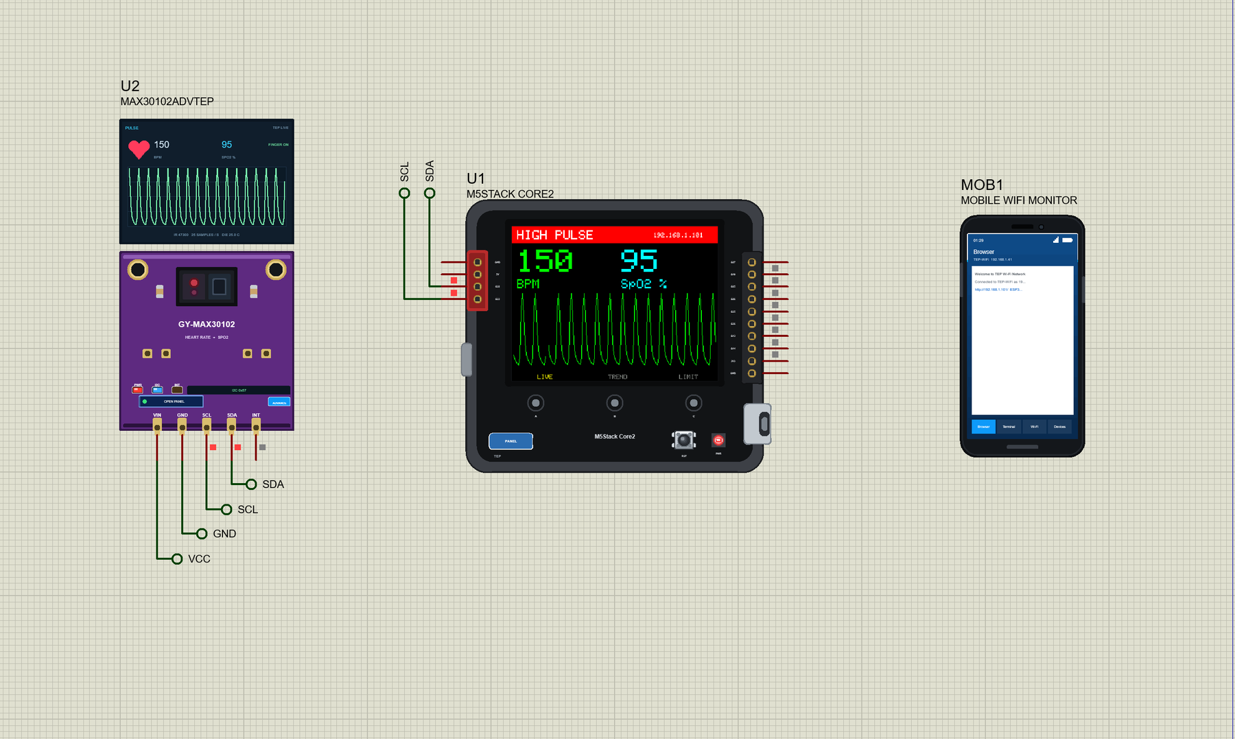
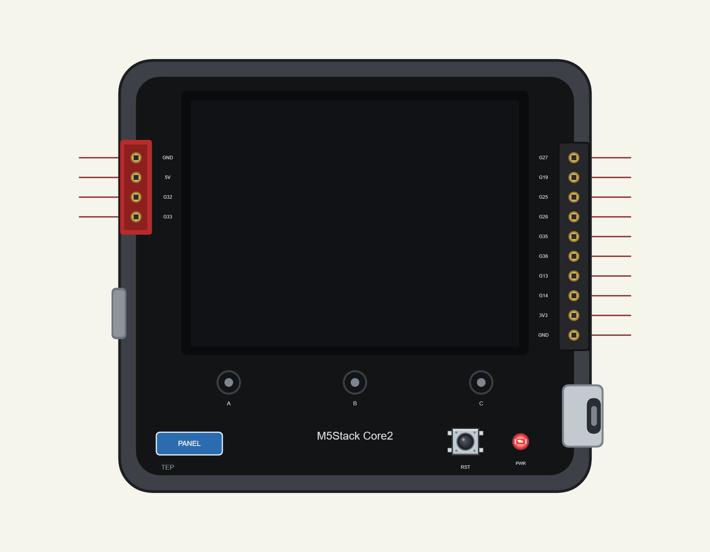
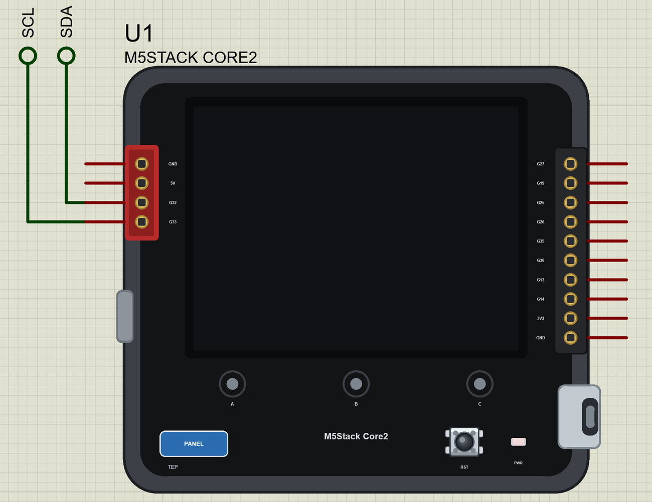
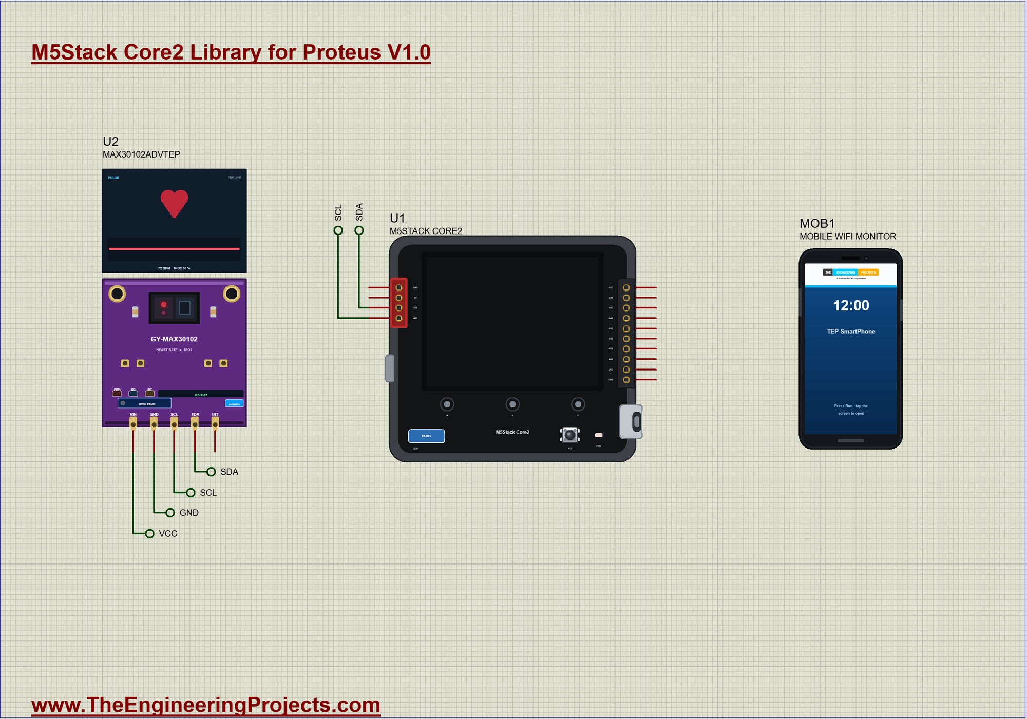
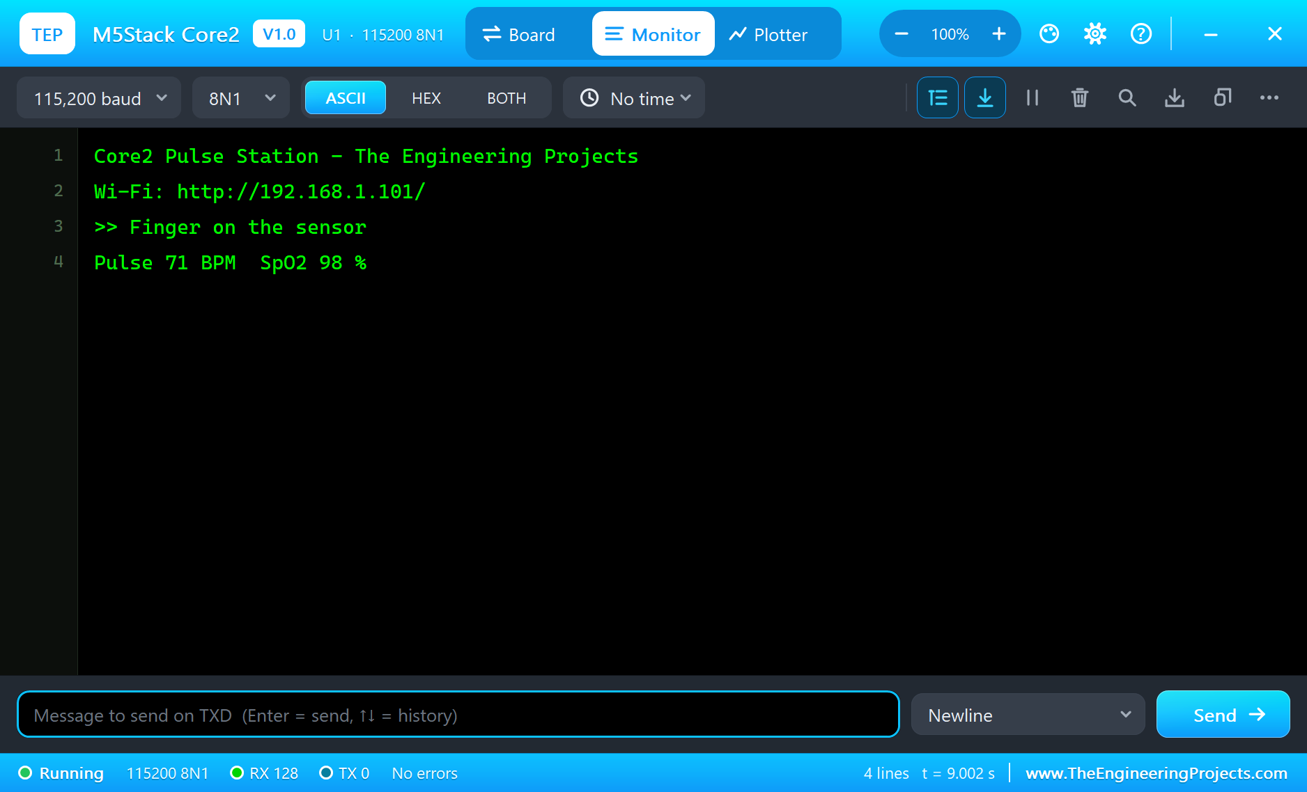
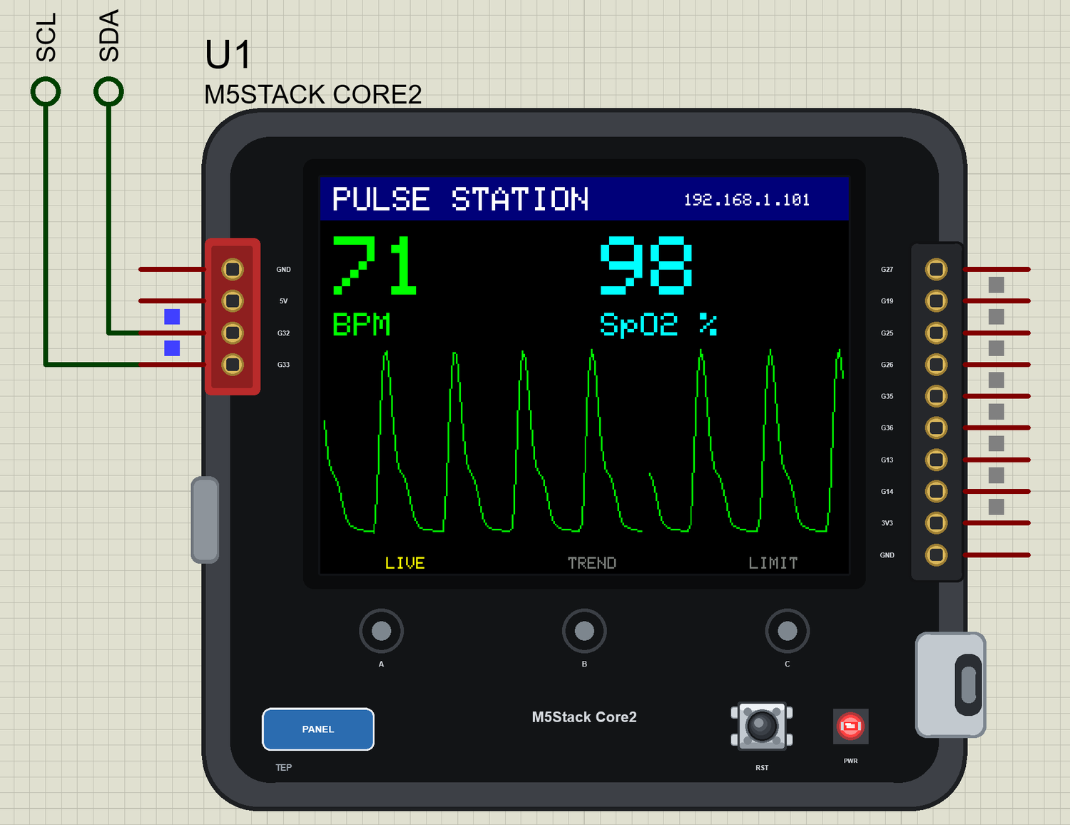
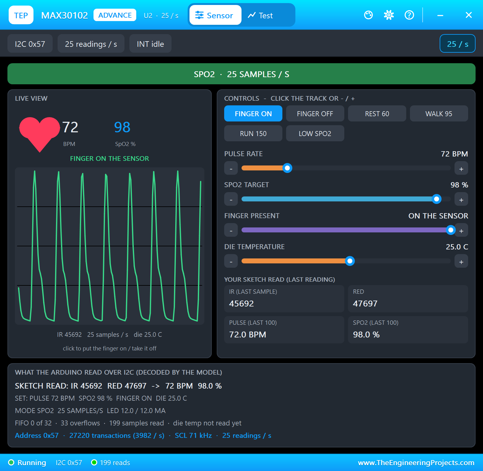
The circuit, the board and the results as they appear in M5Stack Core2 Library for Proteus: ESP32 TFT LCD Touch Screen. Open an image for its full size.
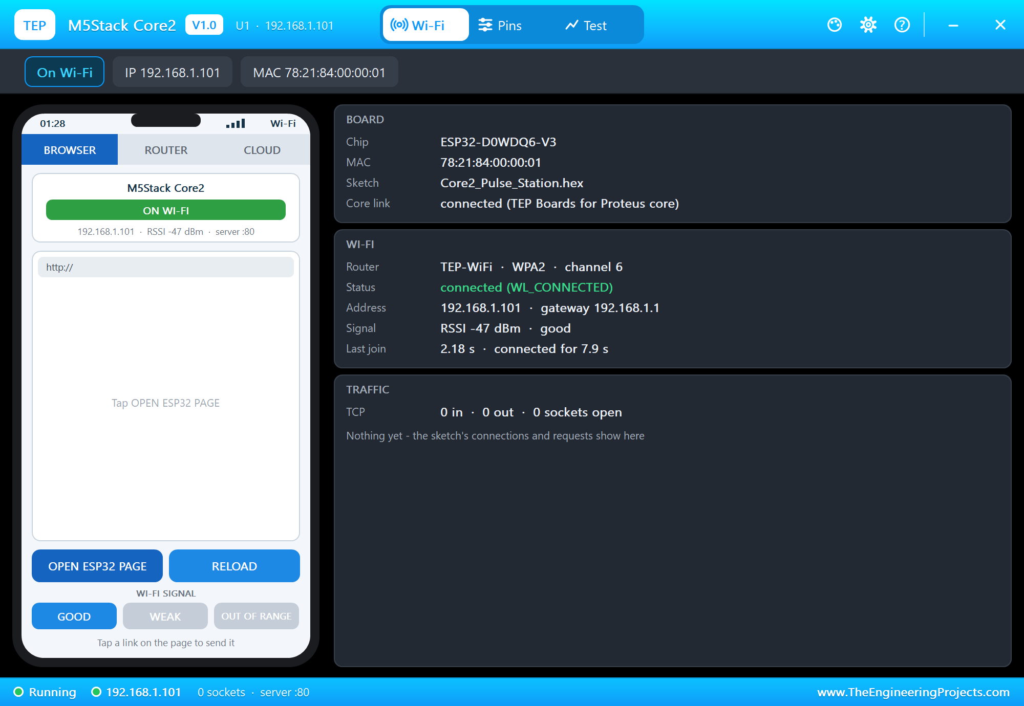
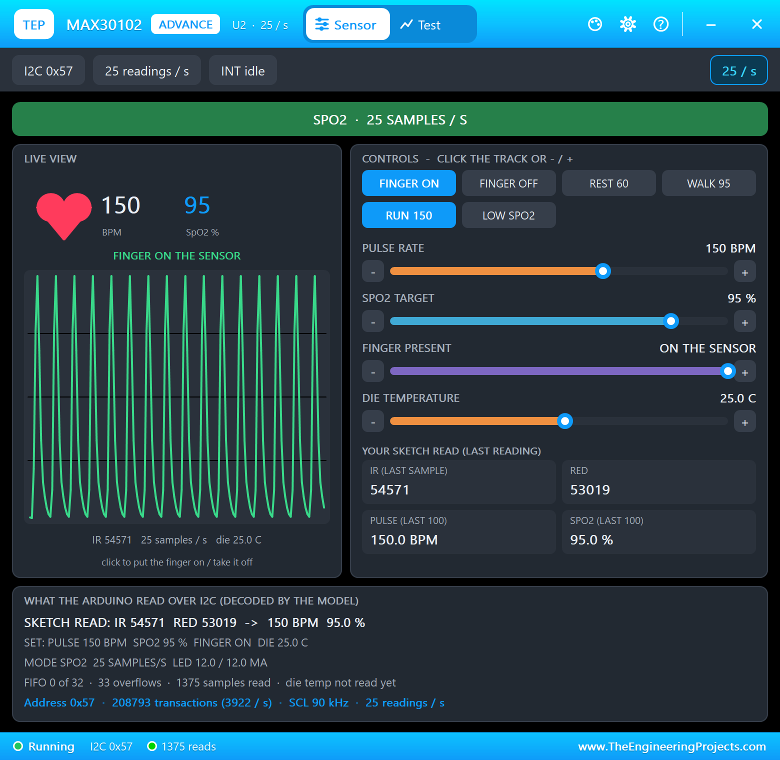
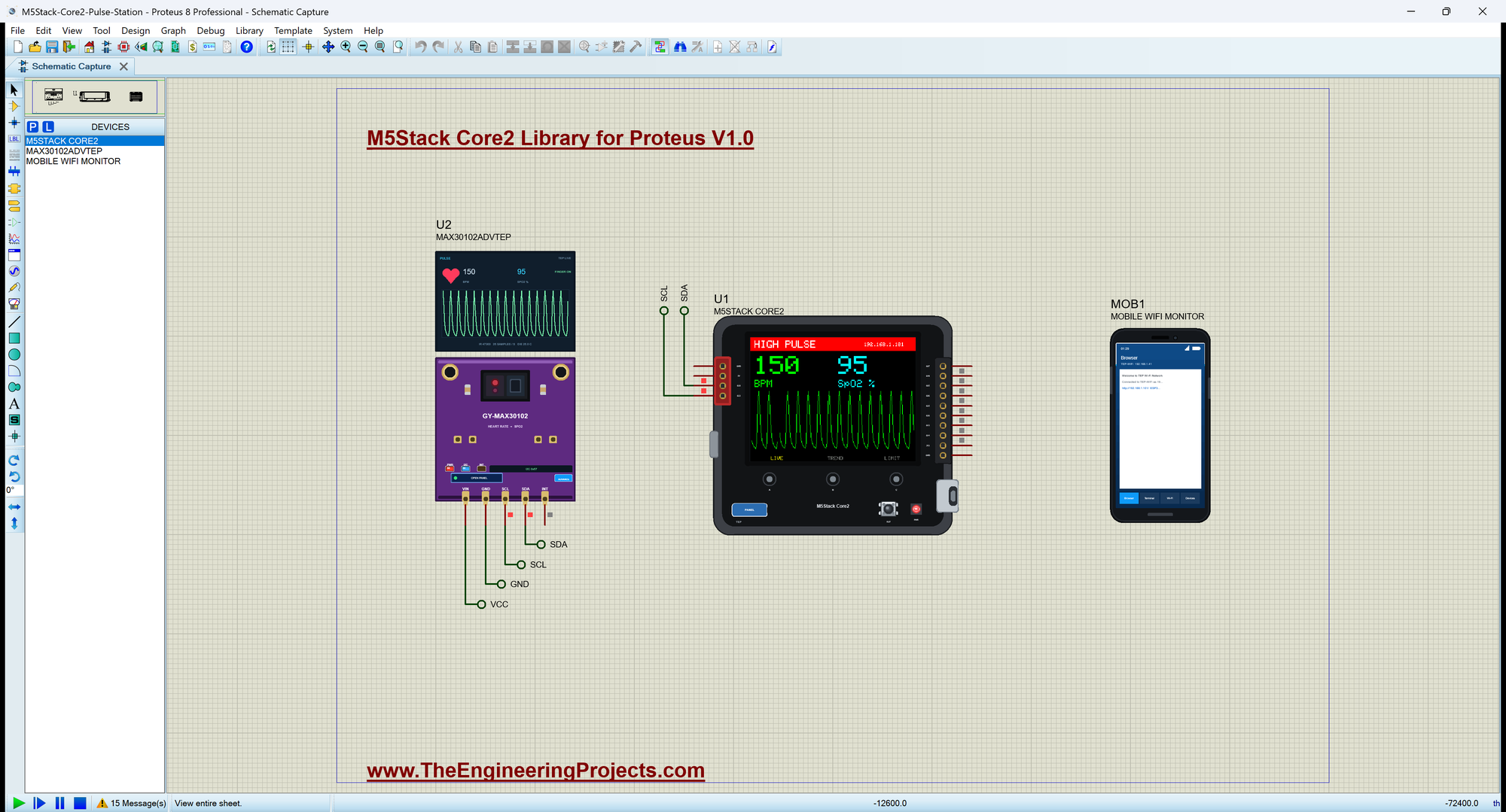
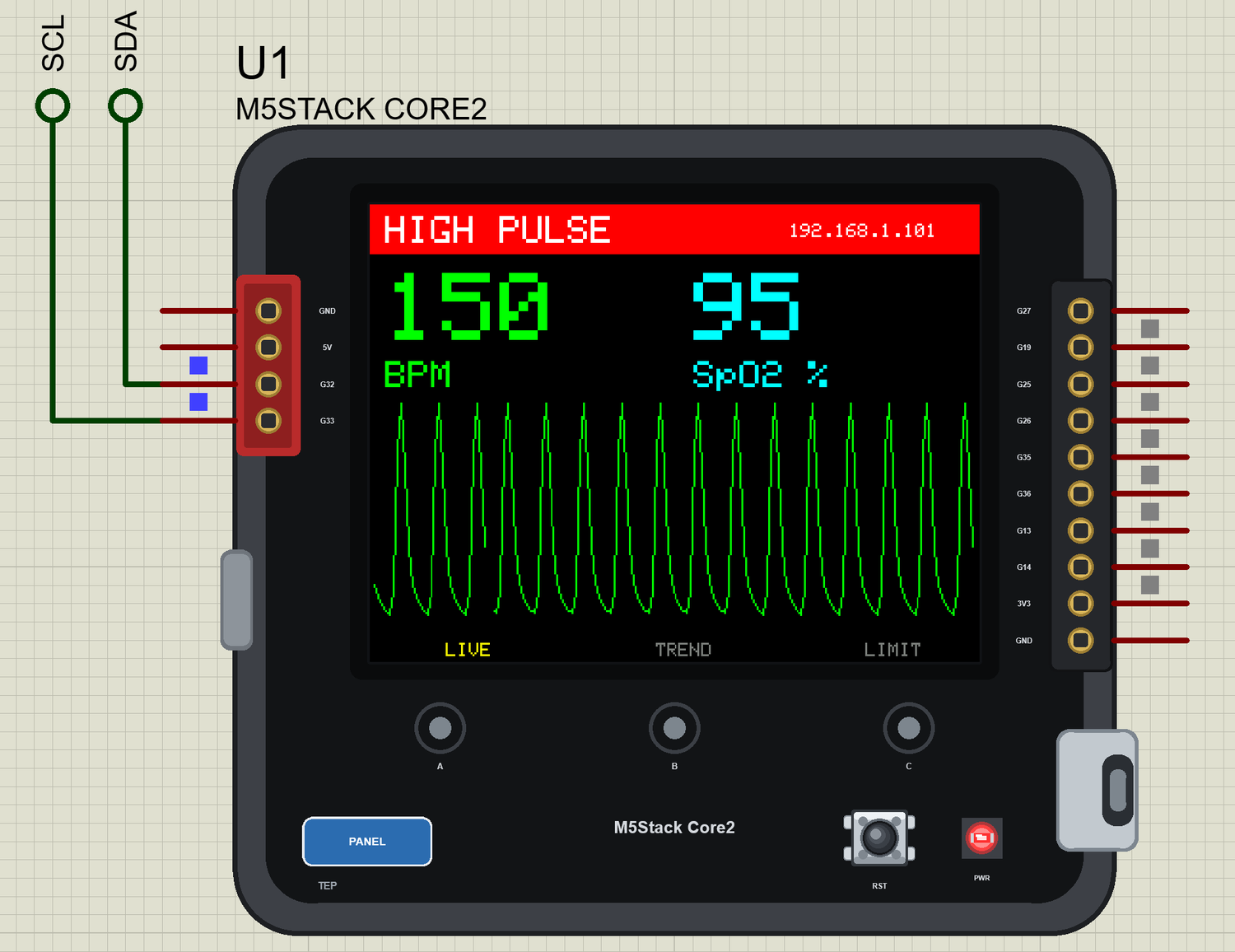
README
 README
M5STACK CORE2 LIBRARY FOR PROTEUS - V1.0 (YOUR ESP32 SKETCH ON THE 2.0" TOUCH SCREEN CUBE)
Designed by The Engineering Projects
www.TheEngineeringProjects.com

IMPORTANT LINKS
Article (read it first - pictures, step by step, every feature explained):
  https://www.theengineeringprojects.com/2026/11/m5stack-core2-library-for-proteus.html
Report a bug or suggest a feature (our forum):
  https://www.theengineeringprojects.com/forum/category/m5stack-core2-proteus-library
The demo's sensor and phone are our libraries (included) - their articles:
  https://www.theengineeringprojects.com/2026/09/max30102-proteus-library.html
  https://www.theengineeringprojects.com/2026/10/mobile-wifi-monitor-library-for-proteus.html
Smaller products from the same maker:
  https://www.theengineeringprojects.com/2026/11/m5stack-atoms3-library-for-proteus.html
  https://www.theengineeringprojects.com/2026/11/m5stickc-plus2-library-for-proteus.html
Support us (the libraries are free):
  https://www.theengineeringprojects.com/donate

FILE STRUCTURE
M5Stack-Core2-TEP-v1.0/
|-- Proteus Library Files/
|   |-- TEPCORE2.LIB                                     25.4 KB   the M5Stack Core2, to LIBRARY
|   |-- TEPLAPTOP.LIB                                    39.5 KB   the laptop (demo), to LIBRARY
|   |-- TEPMAX30102.LIB                                  44.2 KB   the MAX30102 sensor (demo), to LIBRARY
|   |-- TEPMOBILE.LIB                                    13.1 KB   the phone (demo), to LIBRARY
|-- Proteus Model Files/
|   |-- TEPMAX30102.DLL                                 537.0 KB   the MAX30102 sensor, to MODELS
|   |-- TEPNET.DLL                                       2.84 MB   the board + monitors + network, to MODELS
|-- Arduino Code/
|   |-- Core2_Pulse_Station/Core2_Pulse_Station.ino      10.7 KB   the demo sketch
|   |-- TEP Boards for Proteus/hardware/               1,019.0 KB   the Arduino IDE add-on 1.52.0 (229 files)
|-- Proteus Simulation/
|   |-- Core2_Pulse_Station.hex                          99.9 KB   the demo sketch (U1)
|   |-- M5Stack-Core2-Pulse-Station.pdsprj               18.3 KB   the demo: a pulse station
|   |-- TEPMAX30102.DLL                                 537.0 KB   copy of the model
|   |-- TEPNET.DLL                                       2.84 MB   copy of the model
|-- README.txt                                          ~12.0 KB   this file
Total: 7.99 MB (unzipped). The source code of the models is not included.

WHAT IS IT?
Proteus 8 has no ESP32 processor model, so this is NOT a real ESP32 chip. Our team has put a lot of effort into
building this board
ourselves: it is M5Stack's Core2 - the dark square case with an ESP32-D0WDQ6-V3, a 2.0" 320 x 240 ILI9342 display, an
FT6336U capacitive
touch screen with three touch dots under it, a red Grove PORT.A socket and the M-BUS - that runs YOUR ESP32 Arduino
sketch in Proteus:
  * You write a normal sketch (the GPIO numbers of the product, analogRead 0-4095, analogWrite, ledcWrite,
    attachInterrupt, tone,
    Wire, SPI, Serial, WiFi, WebServer, HTTPClient ...) and compile it in the Arduino IDE with our board package "TEP
    Boards for
    Proteus" 1.52.0 (in Arduino Code - see INSTALLATION).
  * The display is ON the part: Adafruit_ILI9341 tft(TFT_CS, TFT_DC) with tft.begin() and tft.setRotation(1) stands
    upright.
  * The touch is real: click the glass or a dot with the mouse, and Wire1 reads the place from the FT6336U at 0x38.
  * Wire is PORT.A (G32, G33); Wire1 is the inside bus. The AXP192 at 0x34 answers too (a plain set of registers).
On the real product the M-BUS is at the back; we drew ten of its pins on the right, so that you can wire them. It is
drawn at about the same
width as the real product and a little lower.
TEP additions: the PANEL pad opens the board's panel, the USB-C port opens the serial monitor.
Limits (say them before you start): your sketch gets 8 KB of RAM in the simulation (the real one: 520 KB plus 8 MB of
PSRAM), about 256 KB of
flash, int is 16 bits in the simulation (use long / int32_t for big numbers), no FreeRTOS tasks, no second core, no
Bluetooth, no ESP-IDF, no
real TLS, no soft AP. The MPU6886, the BM8563 clock, the speaker, the microphone, the vibration motor and the TF card
are NOT modelled, the
AXP192 does not switch anything here, and the M5Core2 / M5Unified / LVGL libraries are not for this part: use the pins
directly.
See MODEL SCOPE AND LIMITS.

ONE DEVICE (search "CORE2" in Pick Devices):
  M5STACK CORE2  "M5Stack Core2" V1.0 (Microprocessor ICs > ESP32 Boards), prefix U, model TEPNET.DLL. Two TEP
  windows, none with
  a Windows title bar: the panel (the PANEL pad: Wi-Fi, Pins, Test, Settings, Help) and the serial monitor (the USB-C
  port, 115200 baud:
  Monitor, Plotter and Board tabs).
The same TEPNET.DLL also runs our other Wi-Fi boards; it replaces any older TEPNET.DLL (keep only this newest one in
MODELS).

TEST STATUS
V1.0: verified in Proteus 8.5 on 31 Oct 2026 with the demo project as shipped. What the Proteus run showed:
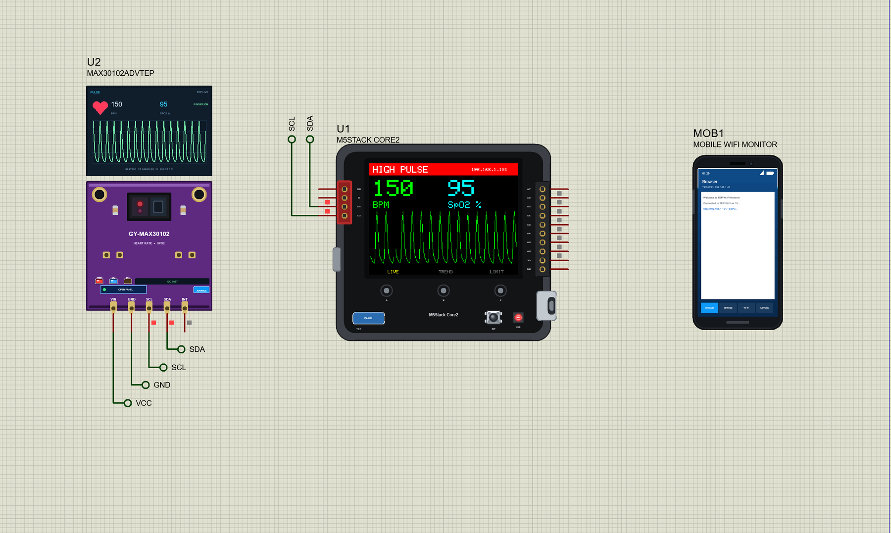
* M5Stack-Core2-Pulse-Station: the monitor printed "Wi-Fi: http://192.168.1.101/" and an estimate every 4 s; the
  display showed the pulse waveform, the heart rate and the oxygen level.
* RUN 150 on the MAX30102's window: ">> HIGH PULSE", the red band. The dot C and + on the glass: ">> Back to normal",
  ">> High pulse limit 160 BPM".
* REST 60, then LOW SPO2: ">> LOW OXYGEN". The dot B: the TREND page. The phone's LIMIT -10: ">> High pulse limit 150
  BPM". FINGER OFF: ">> No finger".
* Real mouse clicks on the part: the dot C and + on the glass did the same.
* about 105 s of simulation, no errors, with the pop-ups, the panel and the monitor open.

INSTALLATION (about 3 minutes)
1. Close Proteus. Extract the WHOLE ZIP to a normal folder (e.g. Desktop).
2. Copy everything in "Proteus Library Files" to the LIBRARY folder of Proteus, for example:
     C:\Program Files (x86)\Labcenter Electronics\Proteus 8 Professional\LIBRARY
   (on some PCs: C:\ProgramData\Labcenter Electronics\Proteus 8 Professional\LIBRARY). TEPCORE2.LIB is the board; the
   others
   are the demo's parts: TEPMAX30102.LIB, TEPLAPTOP.LIB and TEPMOBILE.LIB.
3. Copy the DLLs from "Proteus Model Files" (TEPNET.DLL, TEPMAX30102.DLL) to the MODELS folder (...\Proteus 8
   Professional\MODELS) -
   replace an older TEPNET.DLL (this one is the first that knows the Core2).
4. Delete TEPCORE2.IDX from the LIBRARY folder if it is there.
5. The Arduino IDE (only to compile your own sketches - the demo has its HEX file): copy the folder
   "Arduino Code\TEP Boards for Proteus\hardware" into your sketchbook folder (normally Documents\Arduino), so that
   Documents\Arduino\hardware\tep\avr\boards.txt exists (replace an older copy); restart the IDE. The Arduino AVR Boards
   platform must be installed (it comes with IDE 1.8.x; in IDE 2.x install "Arduino AVR Boards" from the Boards
   Manager once).
   Tools > Board > TEP Boards for Proteus > M5Stack Core2 (TEP Proteus). From the Library Manager: Adafruit ILI9341,
   Adafruit GFX,
   Adafruit BusIO and SparkFun MAX3010x Pulse and Proximity Sensor Library.
6. Start Proteus. In Pick Devices (P) search "CORE2".

RUN THE DEMO
Keep the .hex file and the DLLs beside the project in "Proteus Simulation".
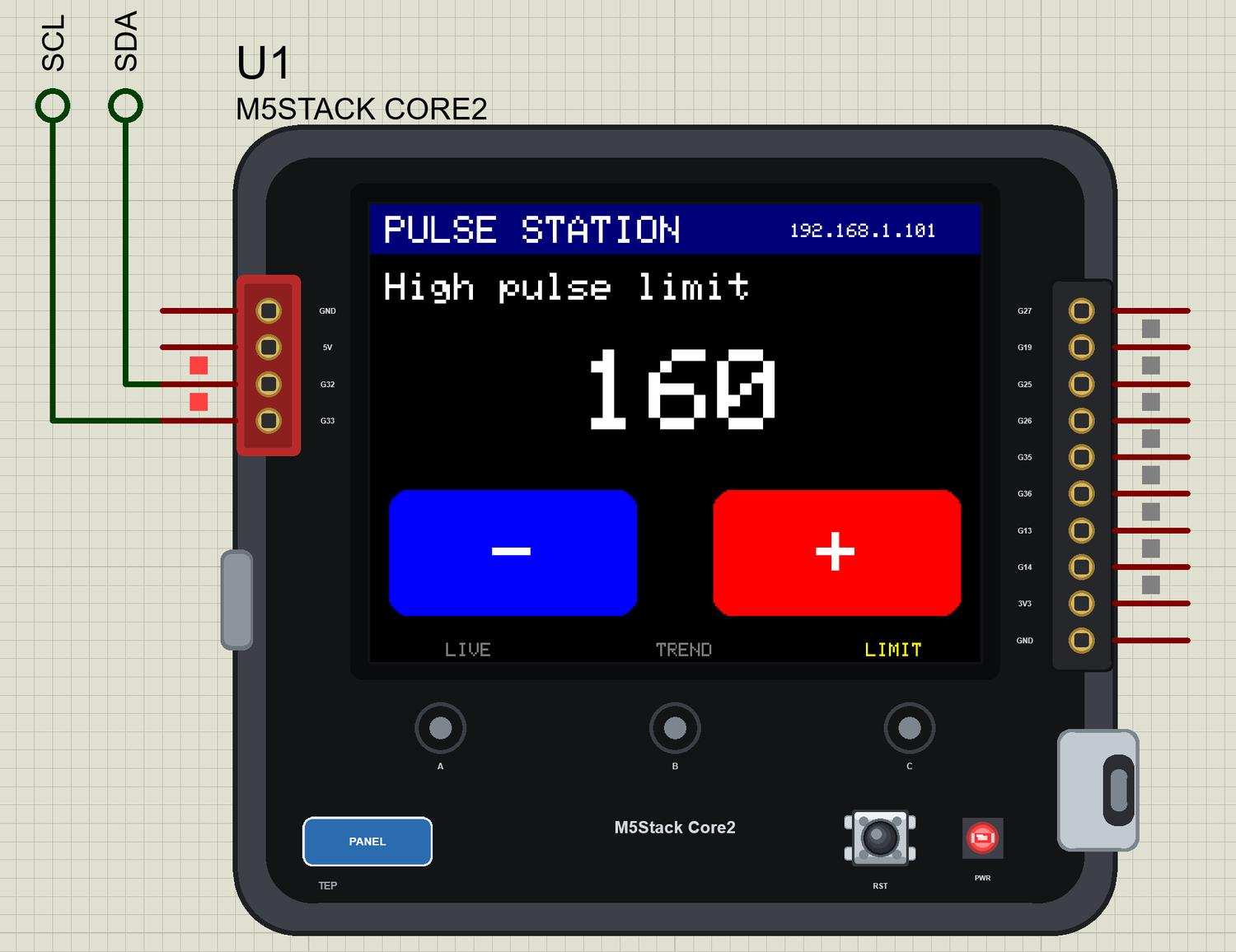
M5Stack-Core2-Pulse-Station.pdsprj - U1 the Core2 (Core2_Pulse_Station.hex) is a pulse station: U2 = a MAX30102
(Advance) on PORT.A, MOB1 = the Mobile
WiFi Monitor on its page. It is a demonstration, not a medical instrument.
Press Run. The screen shows the pulse waveform, the heart rate and the oxygen level. Click RUN 150 on the MAX30102's
window: above the limit a red
band says HIGH PULSE. Click the dot C for the LIMIT page, and + on the glass to raise the limit. The dot A is the LIVE
page, the dot B the TREND page.
LOW SPO2 gives the LOW OXYGEN alarm. On the phone click ESP32 U1 for the page; its links change the limit too.
Closed a window? The USB-C port opens the monitor, the PANEL pad the panel.

THE PINS (the label on the part, what it can do in the simulation)
  G32, G33        PORT.A: Wire SDA / SCL, or GPIO
  G27, G19, G25, G26  the M-BUS: GPIO, PWM, interrupt; analogRead on G27, G25, G26
  G35, G36        the M-BUS: input only, analogRead
  G13, G14        the M-BUS: Serial2 (RX, TX), or GPIO
  3V3, 5V, GND    3.3 V (the logic), 5 V, ground
Inside, not on the sockets: the display (MOSI 23, MISO 38, SCK 18, CS 5, DC 15), the touch's INT 39 and Serial. The
names in sketches: TFT_MOSI ... TFT_DC,
TOUCH_INT, TOUCH_ADDR, AXP192_ADDR, PORTA_SDA, PORTA_SCL, INT_SDA, INT_SCL.

THE TOUCH
Wire1.beginTransmission(TOUCH_ADDR); Wire1.write(0x02); Wire1.endTransmission(); Wire1.requestFrom(TOUCH_ADDR, 5);
then the number of touches and the
X and Y of the first one. X is 0 - 319, Y is 0 - 239 on the glass and 240 or more on the three dots. INT (39) is LOW
while a finger is down.
A click holds the finger down for at least 0.1 s of simulation. Dragging on the glass is not followed.

PROPERTIES (double-click the part > Edit Properties)
  PROGRAM   the sketch's HEX (Arduino IDE: Sketch > Export Compiled Binary with M5Stack Core2 (TEP Proteus))
  WIFISSID  the router in range (default TEP-WiFi);  WIFIPASS  its password (default 12345678)
  MONITOR   YES = the built-in serial monitor on Serial;  BAUD  its speed (115200, or AUTO)
  AUTOOPEN  YES = the monitor window opens at Run (the demo: YES)

TROUBLESHOOTING
* The display stays black: SPI.begin(TFT_SCLK, TFT_MISO, TFT_MOSI, TFT_CS), tft.begin(). On a real Core2 the AXP192
  must switch it on first.
* The picture is upside down: tft.setRotation(1).
* The touch does nothing: pinMode(TOUCH_INT, INPUT), and Wire1.begin(INT_SDA, INT_SCL).
* The MAX30102 is not found: it is on PORT.A, Wire.begin(PORTA_SDA, PORTA_SCL).
* An integer goes wrong above 32767: int is 16 bits in the simulation - use long.

BUG REPORTS AND FEATURE REQUESTS
Please post them in our forum with a screenshot and the Serial Monitor text:
  https://www.theengineeringprojects.com/forum/category/m5stack-core2-proteus-library

LICENCES AND THIRD-PARTY NOTES
* The board model (TEPNET.DLL), the symbols and artwork (TEPCORE2.LIB) and the sensor model are made by The
  Engineering Projects. The
  source code of the models is not included.
* TEP Boards for Proteus (Arduino Code): its core, the variants and the EEPROM, SPI and Wire libraries are modified
  copies of the Arduino AVR core 1.8.6 - GNU Lesser General Public License 2.1 (LGPL 2.1, the text:
  LICENSE-LGPL-2.1.txt); its WiFi, WebServer and the other libraries and our core files are MIT (LICENSE-MIT.txt).
* The demo sketch uses Adafruit ILI9341, Adafruit GFX, Adafruit BusIO and the SparkFun MAX3010x library: install them
  with the Library Manager to rebuild.
* Proteus is a product of Labcenter Electronics and is not included. M5Stack and Core2 are names of M5Stack and ESP32
  of Espressif Systems.
  This library is not made or endorsed by them or by Labcenter.

REBUILDING THE FIRMWARE (OPTIONAL)
The HEX file is supplied. Install TEP Boards for Proteus (INSTALLATION step 5), open Arduino Code\Core2_Pulse_Station,
select M5Stack Core2 (TEP Proteus)
and use Sketch > Export Compiled Binary. For a real one select "M5Stack Core2" in Espressif's "esp32" package, start
the AXP192 with M5Unified, define
the pins of the variant and upload.

MODEL SCOPE AND LIMITS
Modelled: the GPIOs on the sockets; digital I/O, analogRead 0 .. 4095, PWM (analogWrite / ledc), tone and
attachInterrupt through the board model; Serial
(the board's monitor), Serial2, Wire and SPI; the ILI9342 display and the FT6336U touch; WiFi station mode, DHCP, TCP,
UDP, WebServer, HTTPClient and mDNS.
Not modelled: the ESP32 itself (the two 240 MHz cores, the PSRAM, the flash), the MPU6886, the BM8563, the speaker,
the microphone, the vibration motor,
the TF card, the battery, Bluetooth. The AXP192 is a set of registers only. The simulation runs below real time.

VERSION
TEP M5Stack Core2 library V1.0 (Nov 2026). Device M5STACK CORE2 (TEPCORE2.LIB / TEPNET.DLL), TEP Boards for Proteus
1.52.0 (adds the Core2). Demo sketch
Core2_Pulse_Station V1.0. Demo parts: MAX30102ADVTEP and MOBILE WIFI MONITOR.Development1 release
 Development1 release
-
V1.0M5Stack Core2 Library for Proteus V1.0this page
V1.0 is the only release in the Download Center so far. When a newer version is published, it appears above with its own download page.
Installation10 steps
 Installation10 steps
From the download to a working project, in order. The steps follow what the package contains.
You will need
- Proteus Design SuiteProteus 8 or newer (Labcenter), on Windows
- Arduino IDE1.8 or 2.x, with the board of the tutorial chosen under Tools → Board
- The compiler named in the tutorialto build the source files into firmware
- Any archive toolWindows, macOS and Linux extract ZIP files on their own

Steps
- 1
Extract the archive
Right-click m5stack-core2-tep-v1-0-a9cc462301d240808e032b4086b41335.zip and choose Extract All (or open it with 7-Zip or WinRAR) into a folder you can find again. Keep its folder structure (M5Stack-Core2-TEP-v1.0) as it is.
- 2
Copy the library files into Proteus
Move TEPCORE2.LIB, TEPLAPTOP.LIB and TEPMAX30102.LIB and 1 more and the files into the LIBRARY folder of your Proteus installation: C:\Program Files (x86)\Labcenter Electronics\Proteus 8 Professional\LIBRARY for Proteus 8, or the matching Proteus 7 folder. Older versions keep it under ProgramData\Labcenter Electronics. If Proteus is open, close it first.
- 3
Add the simulation model
Copy TEPMAX30102.DLL and TEPNET.DLL into the MODELS folder next to LIBRARY, so the component can run, not only be drawn.
- 4
Restart Proteus and place the component
Start Proteus, open a schematic, press P (Pick Devices) and search for the component by the name used in the tutorial. It appears with its pins ready to wire.
- 5
Install the Arduino library
In the Arduino IDE choose Sketch → Include Library → Add .ZIP Library and pick the library, or copy its folder into Documents\Arduino\libraries. Restart the IDE to see its examples.
- 6
Open the sketch in the Arduino IDE
Open Core2_Pulse_Station.ino, eeprom_clear.ino and eeprom_crc.ino and 17 more, select your board and port under Tools, then Verify. Sketch → Export Compiled Binary writes the HEX file a simulation needs.
- 7
Build the source code
Open abi.cpp, Arduino.h and binary.h and 52 more in the compiler named in the tutorial (MikroC, Keil, MPLAB, Code Composer or the Arduino IDE) and build it to get the firmware.
- 8
Load the HEX file
In Proteus double-click the microcontroller, set Program File to Core2_Pulse_Station.hex and run the simulation. For real hardware, flash the same file with your programmer.
- 9
Open the example simulation
Open M5Stack-Core2-Pulse-Station.pdsprj in Proteus to see the wiring exactly as in the tutorial. Check the controller's Program File path, then press Play.
- 10
Follow the tutorial
M5Stack Core2 Library for Proteus: ESP32 TFT LCD Touch Screen explains every connection and setting in order; keep it open beside the files while you build.
FAQs9 questionsContact TEP
 FAQs9 questions
How do I download M5Stack Core2 Library for Proteus V1.0?
Wait for the 30-second guest countdown on this page, then press the download button; the file comes straight from our storage. Members who are logged in skip the wait. If the browser opens the file instead of saving it, use its Save as option. The download link is made for you when the countdown ends and works for 15 minutes; a saved or shared link stops working, so share this page instead.
What is inside the archive?
M5Stack Core2 Library for Proteus V1.0 comes as a ZIP archive of 241 files (3.6 MB, 8.0 MB unpacked) holding Proteus library files, simulation model DLLs, a Proteus simulation, an Arduino sketch, an Arduino library, compiled HEX firmware and source code. Open the File Structure tab for the full list of 241 files.
What should I do if the download does not start?
Check the browser's download list first; an ad blocker or a company firewall can also hold it back, so try another browser or network. If the file arrives incomplete, download it again. For an installation problem, read the Install tab or tell us in the comments with your software version and the exact error message.
Is this file free?
Yes. Every file in the TEP Download Center is free for learning, personal and student projects. If you share it, link back to this page or the tutorial so others find the latest version.
How do I check that the file arrived complete?
Compare its SHA-256 with the one on this page, 3ec5f4f8180559304b3340aedb4c0a060a39a84f536352ccc6f8b1f069863e78. In PowerShell run Get-FileHash "m5stack-core2-tep-v1-0-a9cc462301d240808e032b4086b41335.zip"; on macOS or Linux run shasum -a 256 "m5stack-core2-tep-v1-0-a9cc462301d240808e032b4086b41335.zip". The same value means the file is exactly the one in our storage; a different one means the download broke off, so download it again.
Do I need WinRAR to open the ZIP file?
No. Windows, macOS and Linux open ZIP archives on their own (Extract All, or double-click). WinRAR and 7-Zip work too. Extract the whole archive before using the files.
Where do I put the LIB and IDX files?
Both files go into the LIBRARY folder of your Proteus installation (Proteus 8: C:\Program Files (x86)\Labcenter Electronics\Proteus 8 Professional\LIBRARY; Proteus 7 has the same folder under its own name). Restart Proteus afterwards and search for the component with P.
Which Proteus version does the library need?
The tutorial names the Proteus version the library was made and tested with. Most TEP libraries work in Proteus 7 and Proteus 8; if the component does not appear after a restart, check that both the LIB and the IDX file were copied and that Proteus was fully closed while copying.
How do I get the HEX file into the simulation?
Compile the sketch in the Arduino IDE (Sketch → Export Compiled Binary gives you the HEX next to the sketch), then in Proteus double-click the board, set Program File to that HEX and run.
Members skip the wait. Log in or join TEP.

- 0Total downloads
- 4%Popularity
- ProteusCategory
- 0Comments
- ssyedzainnasirUploaded by
- 4 Nov 2026Uploaded at


 SHA-256
3ec5f4f8180559304b3340aedb4c0a060a39a84f536352ccc6f8b1f069863e78


 Need help with this file?
 Tags
Related Proteus
All Proteus tutorials
More ESP32 project files
All ESP32 tutorials

Comments
0