


SimpleFOC Mini Driver Library for Proteus Simulation


Hello friends, I hope you all are doing great. Today, I am going to share the new SimpleFOC Mini Driver Library for Proteus Simulation, the 41st library of our motor series. If you have searched for a Proteus simulation of a SimpleFOC driver, this is the small open-source board that the SimpleFOC project made for gimbal motors and field-oriented control (FOC). It carries a DRV8313 with three half-bridges, takes three PWM signals from a microcontroller and turns them into three phase voltages for a brushless motor, with enable, sleep, reset and fault pins around it.
SimpleFOC Mini Driver Library for Proteus Simulation
Latest version: V1.0 (November 2026, this tutorial)
Helping Tools
- Serial Monitor Advance: a serial terminal window for the UART of your board
- Serial Monitor Expert: the serial monitor with extra debugging tools
- LCD Library for Proteus V3.0: 16x2, 20x4 and I2C LCDs to show your readings
Our library brings the SimpleFOC Mini v1.1 into your Proteus simulation at its true size, 26 x 20 mm, with the chip, the input header, the motor and power pads and the optional header. The simulation model follows the DRV8313 datasheet and the board's documentation: every input's PWM is measured period by period, the three outputs follow their inputs, EN opens them all, sleep and reset work as on the chip, and the faults pull nFT low. The pop-up shows the three half-bridges with their duty and current and, above all, the voltage vector that the three outputs make together, which is exactly what a FOC library sets. In the demo an Arduino drives our 2204 gimbal motor through it, the way SimpleFOC does in open loop.
NOTICE: Our team has put a lot of effort into these small parts: the bodies, the animation and the pop-ups are all our own design, and you get them free. Your feedback is the fuel that keeps us going, so please tell us what you think in the comments below or in the Motor Driver board of our forum. And if our free libraries help you, you can buy us a coffee. So, let's get started with the SimpleFOC Mini Driver Library for Proteus Simulation:
What is the SimpleFOC Mini?
SimpleFOC is an open-source library for Arduino and other boards that runs brushless motors with field-oriented control. Its idea is simple: the motor's three phases get three average voltages from three PWM outputs, and together they form a voltage vector that the library can point in any direction and make any size. Turn the vector, and the motor's field turns; keep it 90 electrical degrees ahead of the rotor's magnets, measured by an encoder, and every ampere gives the most torque. The SimpleFOC Mini is the project's smallest driver board for that job, made for gimbal motors, which have high-resistance windings and need no current sensing.
On the board sits a TI DRV8313. It has three independent half-bridges, each a high-side and a low-side MOSFET of 0.24 ohm. Each input pin drives one output: high connects it to the supply, low to ground, and a PWM gives the average in between. The EN pin enables all three; low leaves every output open, so the motor turns free. Three more pins, all active low, give the chip's sleep, reset and fault signals, and the chip's own 3.3 V regulator comes out on a pin for small loads.
| Pin | What it does |
|---|---|
| IN1 IN2 IN3 | the three PWM inputs: high = the output to V+, low = to V- |
| EN | high = enabled; low (or open: pull-down) = all three outputs open |
| GND | the controller's ground (two pins on the board) |
| M1 M2 M3 | the motor's three phases |
| V+ / V- | the supply: 8 to 35 V on this board (the chip itself takes 60 V) |
| nSP | sleep, active low (pulled up on the board) |
| nRT | reset, active low: clears a latched fault |
| nFT | fault output, low = under-voltage, over-current or over-temperature |
| 3V3 | the chip's 3.3 V regulator, 10 mA |
| The DRV8313 (TI datasheet) | |
|---|---|
| Outputs | three half-bridges, 2.5 A peak, 0.24 ohm a switch |
| Supply | 8 to 60 V (absolute 65 V); under-voltage lockout 6.3 to 8 V |
| Protection | over-current 3 to 5 A (5 µs), latched until reset; over-temperature 160 °C |
| Inputs | PWM up to 250 kHz, 90 ns dead time |
| Regulator | 3.3 V, 10 mA |
How Three PWMs Make a Voltage Vector
Each half-bridge gives its phase an average voltage: the duty times the supply. With 12 V and a duty of 50 %, a phase sits at 6 V on average. What turns the motor is not these three voltages themselves but their differences: add the same voltage to all three and nothing changes in the windings. Take away the common part, and the three numbers become one vector on a plane, with a size and an angle. FOC libraries work backwards: they choose a vector, the size Uq for the torque and the angle from the rotor, and turn it into three duties around the middle of the supply.
That is the voltage vector the pop-up draws. When the program turns the vector smoothly, the three duties trace three sine waves 120 degrees apart, the familiar picture of sine PWM. The motor's current follows the vector, and its magnets follow the current.
Features of the SimpleFOC Mini Driver Library for Proteus Simulation
- The board at true scale: the 26 x 20 mm board with the DRV8313, its capacitors, the input header, the motor and power pads and the optional header.
- Three half-bridges: averaged and solved with the motor, 0.24 ohm a switch, synchronous, so the current can flow either way.
- The PWM measured: every edge of IN1, IN2 and IN3 is timed, and the duty of each period drives its output; a steady input is its level.
- EN, sleep and reset: EN low opens all outputs, nSP low sleeps the chip with a 1 ms wake-up, nRT low resets it and clears a latched fault.
- The faults on nFT: under-voltage, a latched over-current per output and over-temperature from the die's losses.
- The voltage vector: the pop-up turns the three outputs into the vector a FOC library sets, its size and electrical angle.
- A pop-up: the half-bridges with their duty, voltage and current, the vector and the duties, the controls and the faults; graphs, an event log and a check page.
- A complete package: about 1.2 MB with the library, our Arduino UNO V4.0 and the demo, without the source code of the model.
The SimpleFOC Mini in Proteus
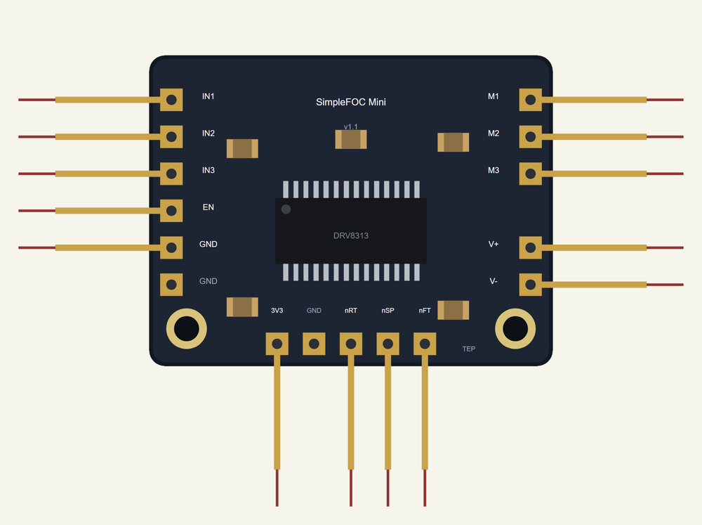
The device is SIMPLEFOCMINITEP in TEPSFOCMINI.LIB, under Electromechanical > Motor Drivers, with the prefix U and the mixed model TEPSFOCMINI.DLL: the inputs and nFT are digital, the half-bridges and 3V3 analog. Search SIMPLEFOC in Pick Devices. The input header is on the left, IN1, IN2, IN3, EN and GND; the motor and power pads on the right, M1, M2, M3, V+ and V-; the optional header along the bottom, 3V3, nRT, nSP and nFT. Like the real board, it has no properties: the pins set everything.
Download SimpleFOC Mini Driver Library for Proteus Simulation
Click the button below to download SimpleFOC-Mini-Driver-Library-for-Proteus-v1.0.zip (about 1.2 MB, without the source code of the models):
SimpleFOC Mini Driver Library for Proteus V1.0- README.txt: installation, the demo, the wiring, troubleshooting and the limits of the simulation.
- Proteus Library Files:
TEPSFOCMINI.LIBandArduinoV4TEP.LIB. - Proteus Model Files:
TEPSFOCMINI.DLLandTEPARDUINO.DLL. - Arduino Code: the demo sketch.
- Proteus Simulation: the demo project, its HEX file and copies of the DLLs.
No Proteus yet? Read How to Download and Install Proteus 7 and 8. New to libraries? Follow How to Install a New Library in Proteus.
How to Install SimpleFOC Mini Driver Library for Proteus Simulation
- Close Proteus and extract the whole zip file, for example to your Desktop.
- Copy the files from Proteus Library Files into the LIBRARY folder of Proteus.
- Copy the files from Proteus Model Files into the MODELS folder.
- Delete
TEPSFOCMINI.IDXfrom the LIBRARY folder if it is there. - The demo's motor is our separate 2204 Gimbal Motor Library for Proteus Simulation: install its LIB and DLL too.
- Start Proteus, press P and search for SIMPLEFOC.
Proteus Simulation of the SimpleFOC Mini with Arduino
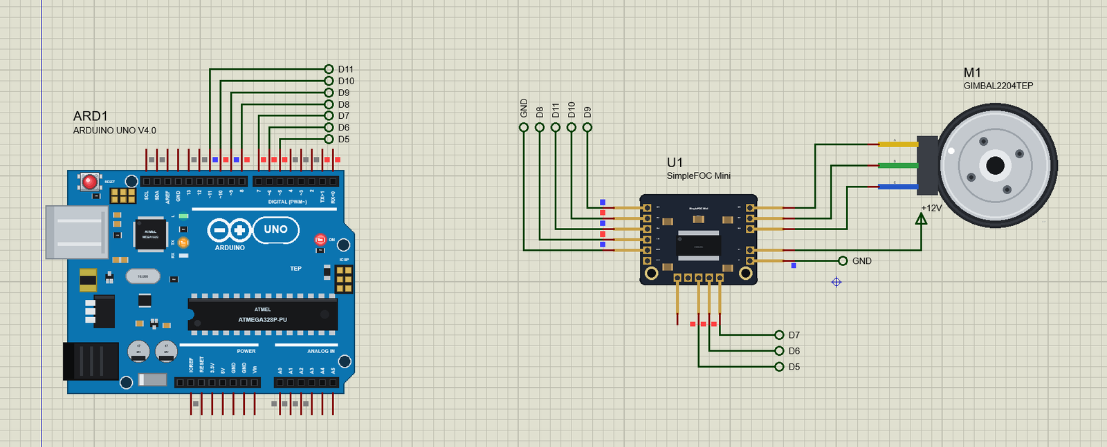
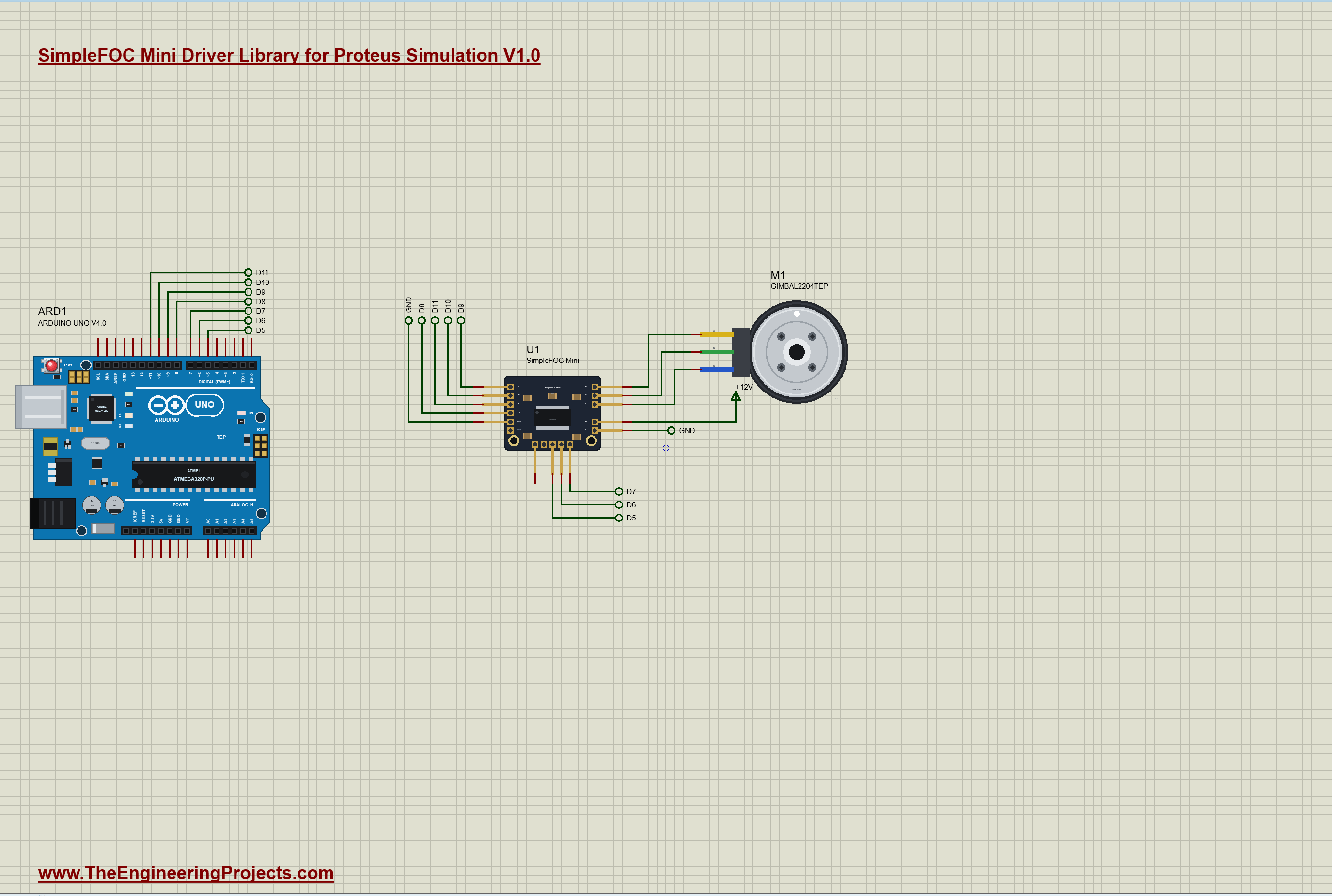
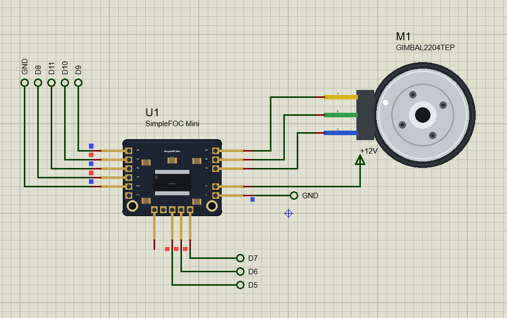
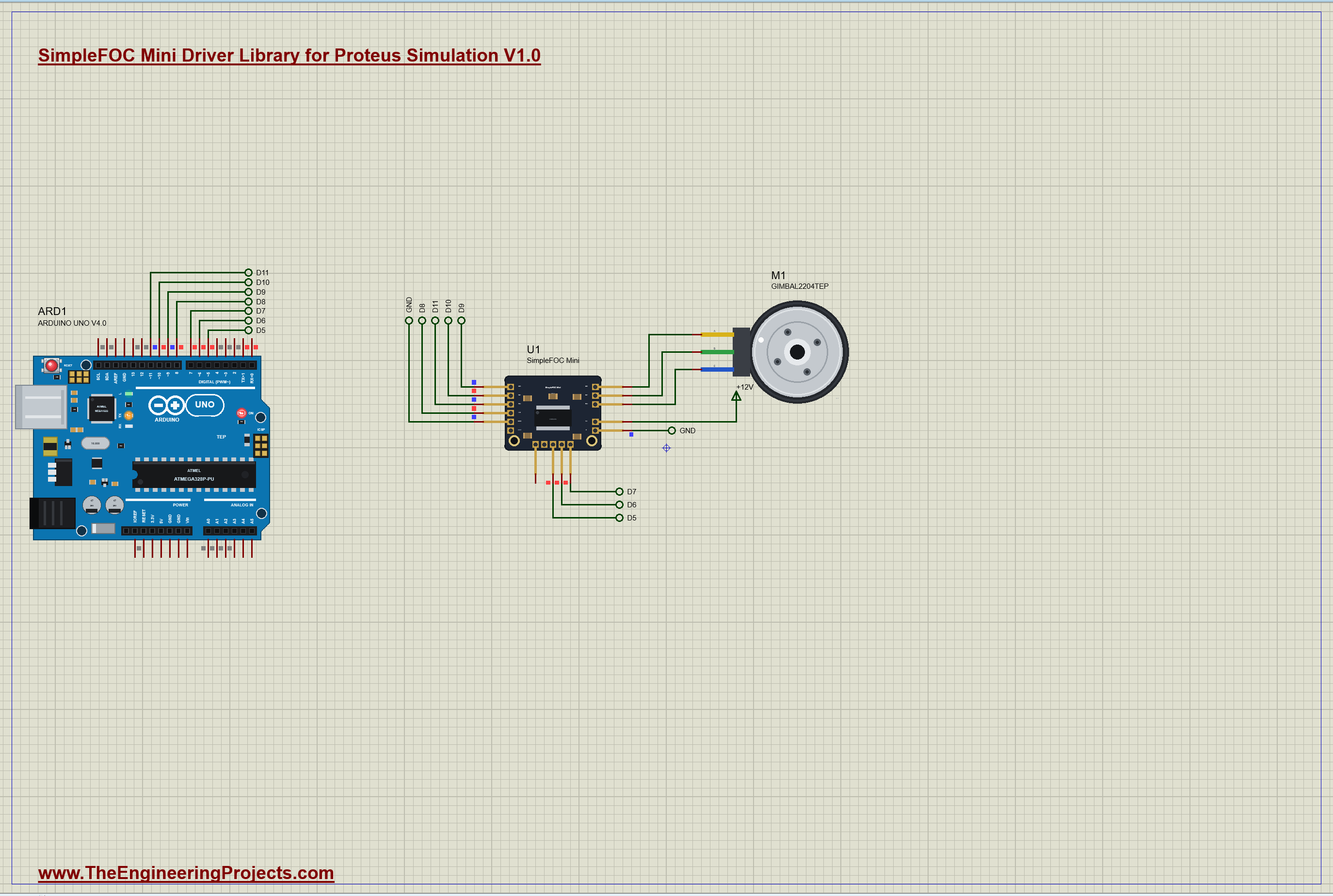
The demo has our Arduino UNO Library for Proteus V4.0 with its built-in monitor, the same window as our TEP Serial Monitor Advance for Proteus. The board U1 sits on a 12 V terminal, and its M1, M2 and M3 run up to M1, the 2204 gimbal motor from our separate 2204 Gimbal Motor library (TEPGIMBAL2204.LIB and TEPGIMBAL2204.DLL), so install it first. D9, D10 and D11 drive IN1, IN2 and IN3; D8 is EN; D5 and D6 drive nRT and nSP; and nFT comes back to D7, so the UNO can print the fault state. Open SFOCMINI-GIMBAL2204-ArduinoUnoV4.pdsprj.
The Sketch
The sketch does what the SimpleFOC library does in open loop, in a few lines and without the library. It sets Timer1 and Timer2 for a 31 kHz PWM on D9, D10 and D11, as SimpleFOC does on an UNO. The heart is SimpleFOC's setPhaseVoltage: a vector of size uq on the q axis at an electrical angle, turned into three phase voltages by the inverse Clarke transform:
void setPhaseVoltage(float uq, float angleEl) {
  float ualpha = -uq * sin(angleEl), ubeta = uq * cos(angleEl);
  float ua = ualpha, ub = -0.5 * ualpha + 0.8660254 * ubeta, uc = -0.5 * ualpha - 0.8660254 * ubeta;
  analogWrite(IN1, dutyOf(ua)); analogWrite(IN2, dutyOf(ub)); analogWrite(IN3, dutyOf(uc));
}
Each phase voltage becomes a duty around the middle of the 12 V supply:
uint8_t dutyOf(float u) { float d = 0.5 + u / VM; return (uint8_t)(constrain(d, 0.0, 1.0) * 255 + 0.5); }The sweep moves the target like a gimbal panning, 60 degrees each way at half a hertz, and the field follows it:
if (mode == SWEEP) target = sweepFrom + 60 * DEG_TO_RAD * sin(TWO_PI * 0.5 * (nowUs - sweepT0) * 1e-6);The board's controls are plain pin writes:
    case A_SLEEP: digitalWrite(NSP_PIN, LOW); break;
    case A_WAKE: digitalWrite(NSP_PIN, HIGH); break;
    case A_EN0: digitalWrite(EN_PIN, LOW); driving = false; break;
    case A_EN1: digitalWrite(EN_PIN, HIGH); driving = true; break;
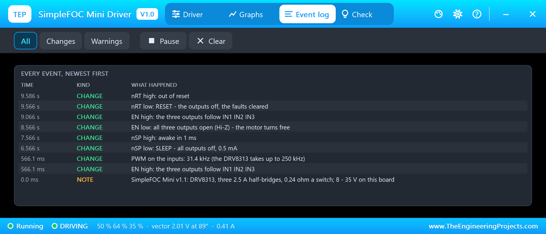
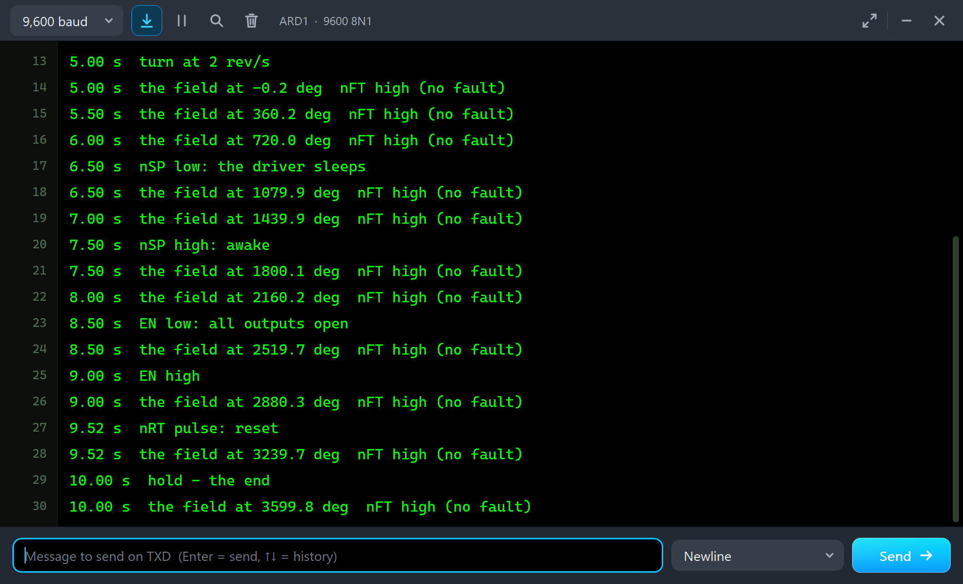
The program: EN high and hold at 0.5 s, the sweep at 1 s, 2 rev/s at 5 s, sleep at 6.5 s, awake at 7.5 s, EN low at 8.5 s, EN high at 9 s, a reset pulse at 9.5 s and a hold at 10 s. Afterwards you can type v 2, a 45, s 0 or s 1, and e 0 or e 1 in the monitor.
SimpleFOC Mini Simulation Results
Open the project and press Run. The program runs about 10.4 simulated seconds, which Proteus ran in about three and a half minutes on our PC with both pop-ups open and the pictures being taken. Click the board to open its pop-up. Every number below comes from one simulation run, the demo exactly as it ships.
Enabled and Holding
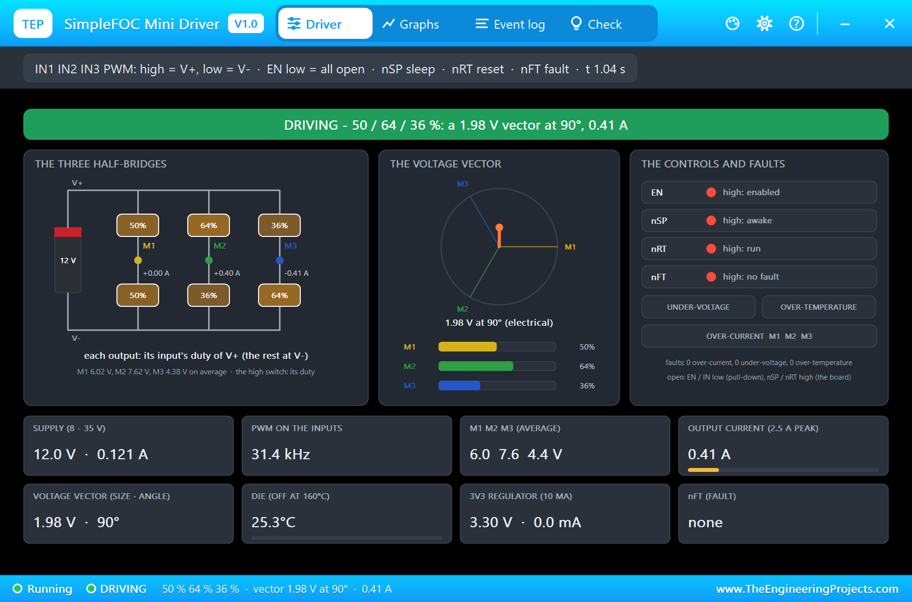
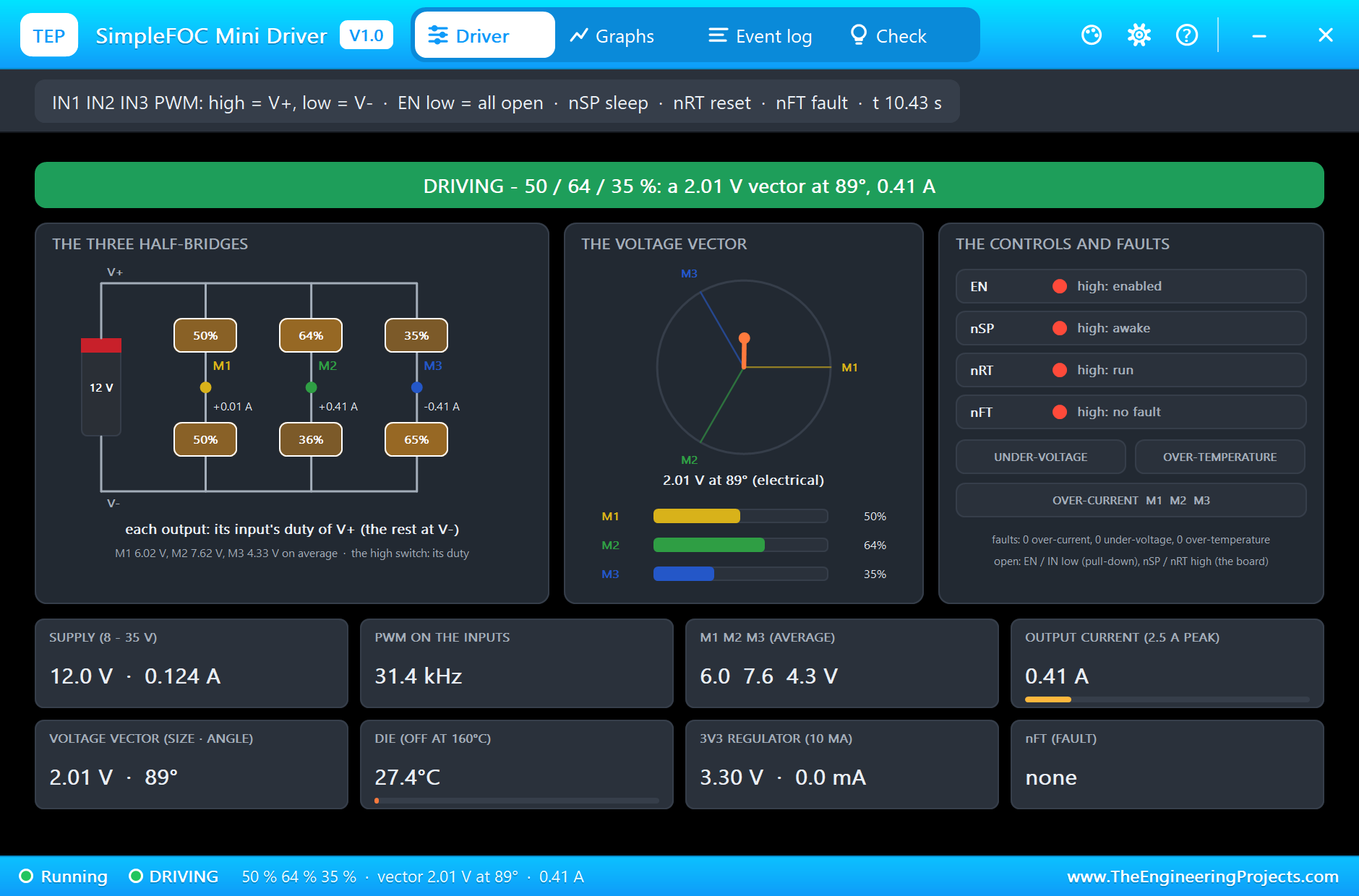
At 0.5 s the UNO sets EN high. The Event log notes the PWM on the inputs at 31.4 kHz, well under the DRV8313's 250 kHz. The vector stands still at 2 V, and the motor's magnets snap to it and hold, at 11.5 degrees with 0.47 A. In the picture each switch is lit by its share of the period: the duties are about 50, 64 and 36 %, and the vector points straight up, at 90 degrees, the q axis of an angle of zero.
The Pan Sweep
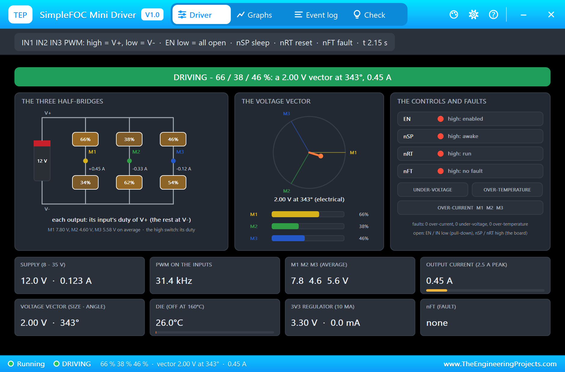
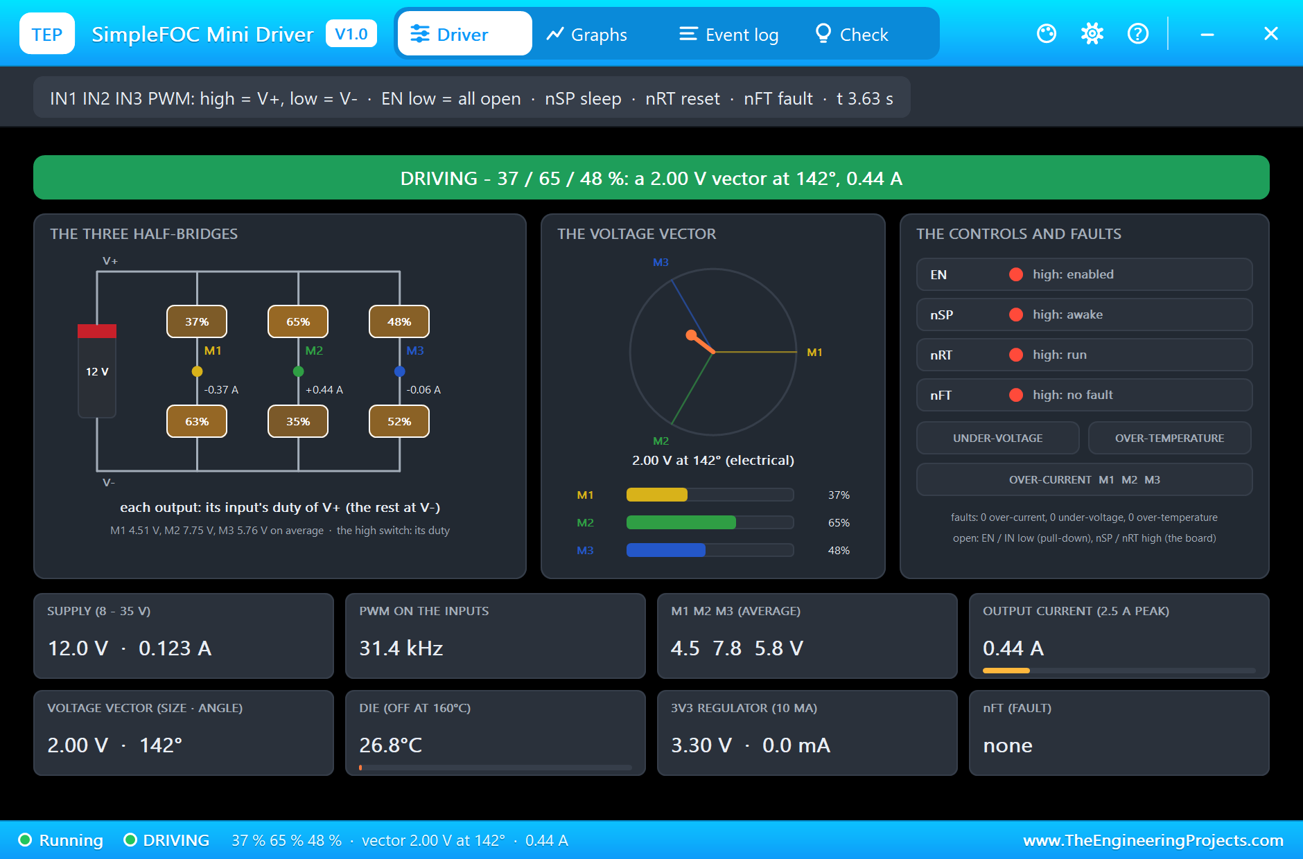
From 1 s the target sweeps 60 degrees each way, twice in four seconds. Now the three duties keep changing: in the picture they are 66 / 38 / 46 %, which gives average outputs of 7.8, 4.6 and 5.6 V and a vector of 2.00 V at 343 degrees. The phases carry 0.45 A, but the supply gives only 0.123 A, because it delivers current only while a high side is on. The vector card shows the arrow turning back and forth as the sweep runs, and the motor follows at up to about 31 RPM.
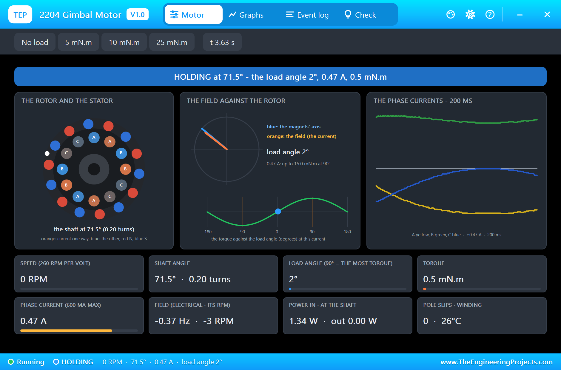
The motor's own pop-up shows the same moment from the motor's side: the field against the magnets, a small load angle, and the phase currents in the scope.
Turning at 2 rev/s
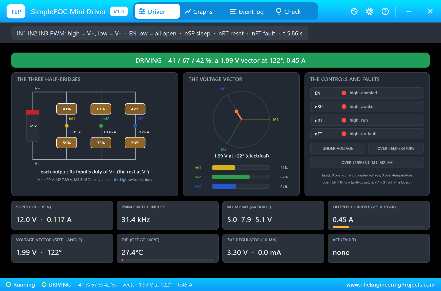
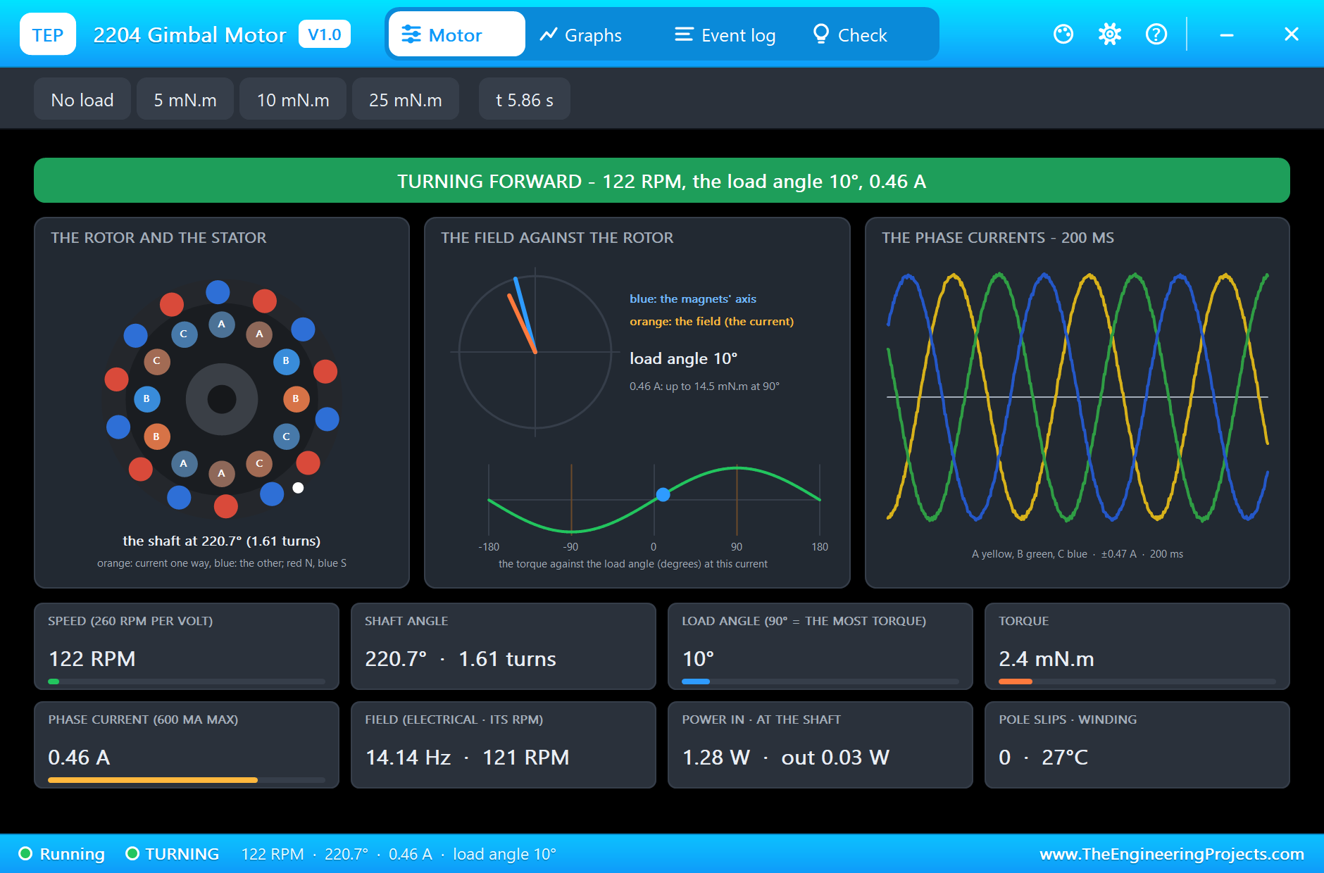
At 5 s the sketch turns the field at 2 revolutions a second. The vector now goes round 14 times a second, seven electrical turns for each turn of the shaft. In the picture the duties are 41 / 67 / 42 %, the vector 1.99 V at 122 degrees, 0.45 A in the phases and 0.117 A from 12 V. The motor turns at 122 RPM, in step with the field.
Sleep, Disable and Reset
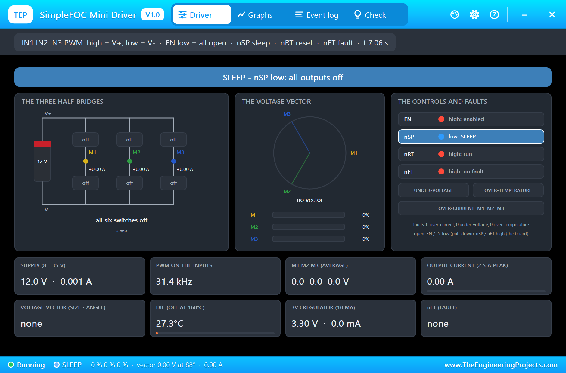
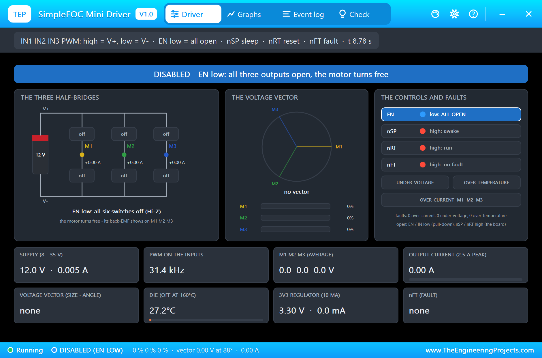
At 6.5 s the sketch pulls nSP low. The driver goes to sleep: all six switches off, the supply current falls to 0.001 A, and the motor coasts to rest. The pop-up marks nSP in blue, SLEEP, and the vector card says no vector. At 7.5 s nSP goes high; after the chip's 1 ms wake-up the outputs follow the inputs again. The field has kept turning in the program, so it picks the motor up where the program is, and it runs in step again at 120 RPM.
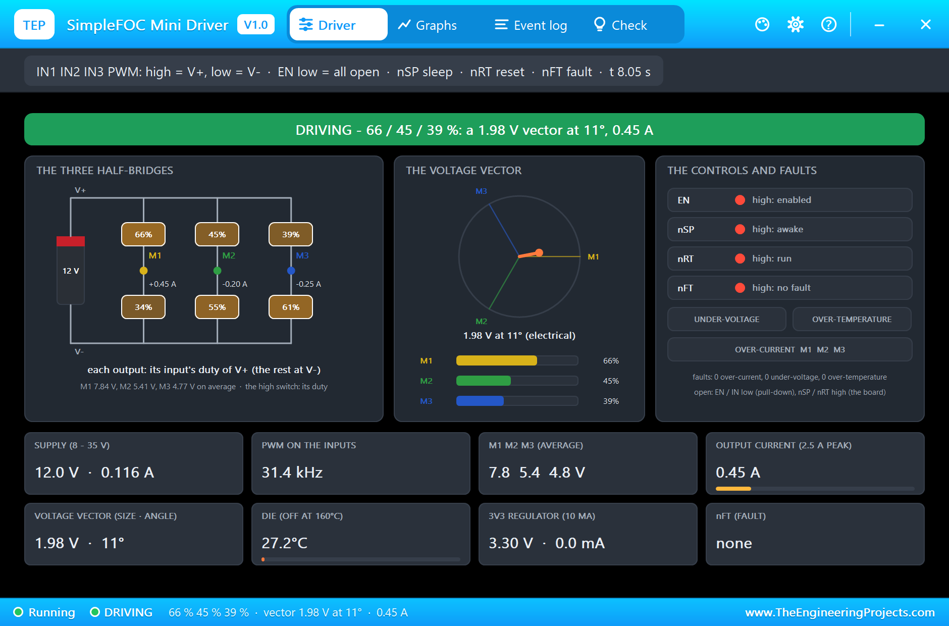
At 8.5 s EN goes low: DISABLED, all three outputs open, 0.005 A from the supply, and the motor turns free. EN high at 9 s brings the outputs back. At 9.5 s a 20 ms pulse on nRT resets the chip: the outputs go off for that moment and any latched fault is cleared. At 10 s the sketch holds the motor. nFT stayed high through the whole run, so no fault happened.
The Graphs, the Event Log and the Check Page
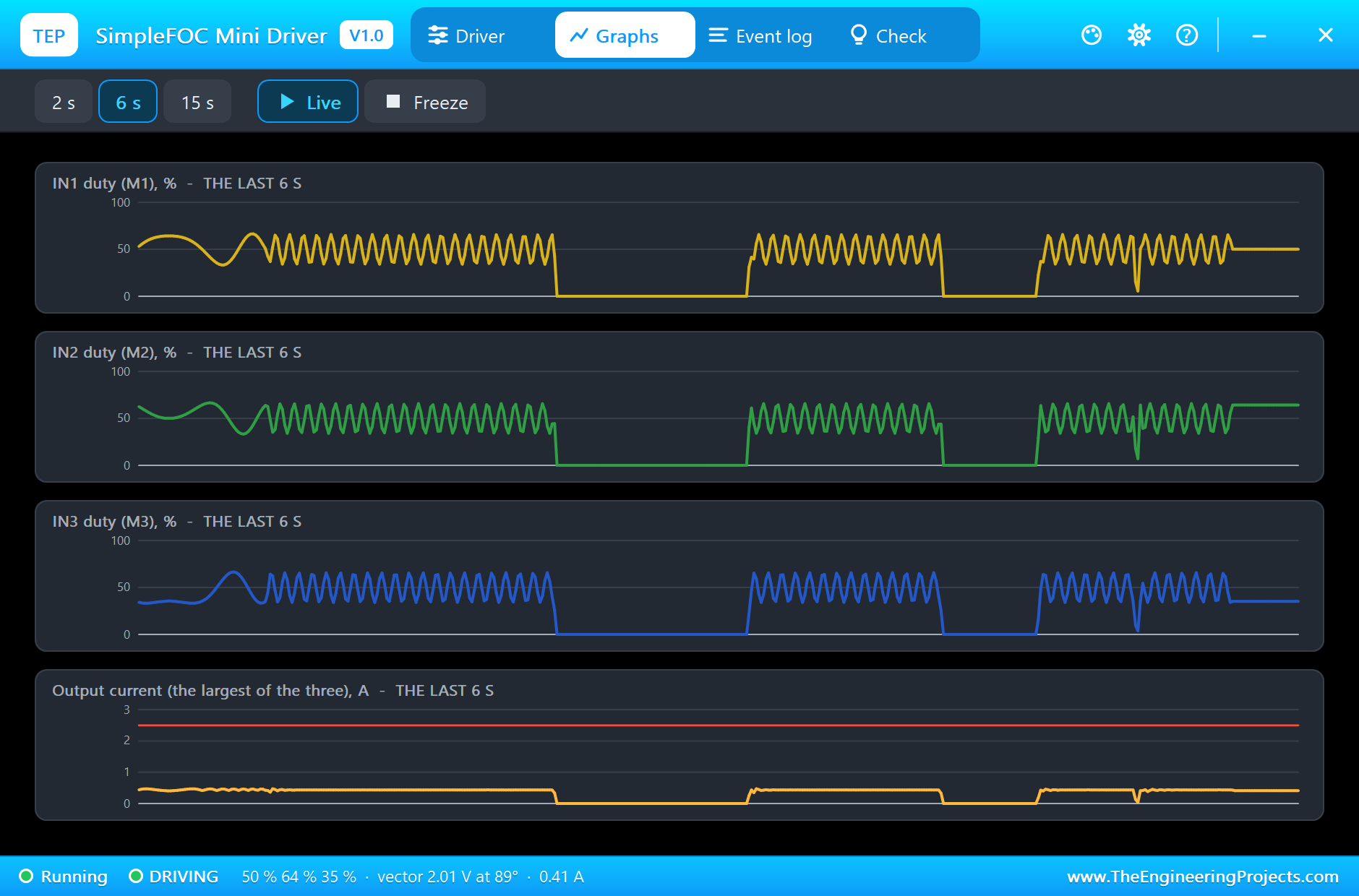
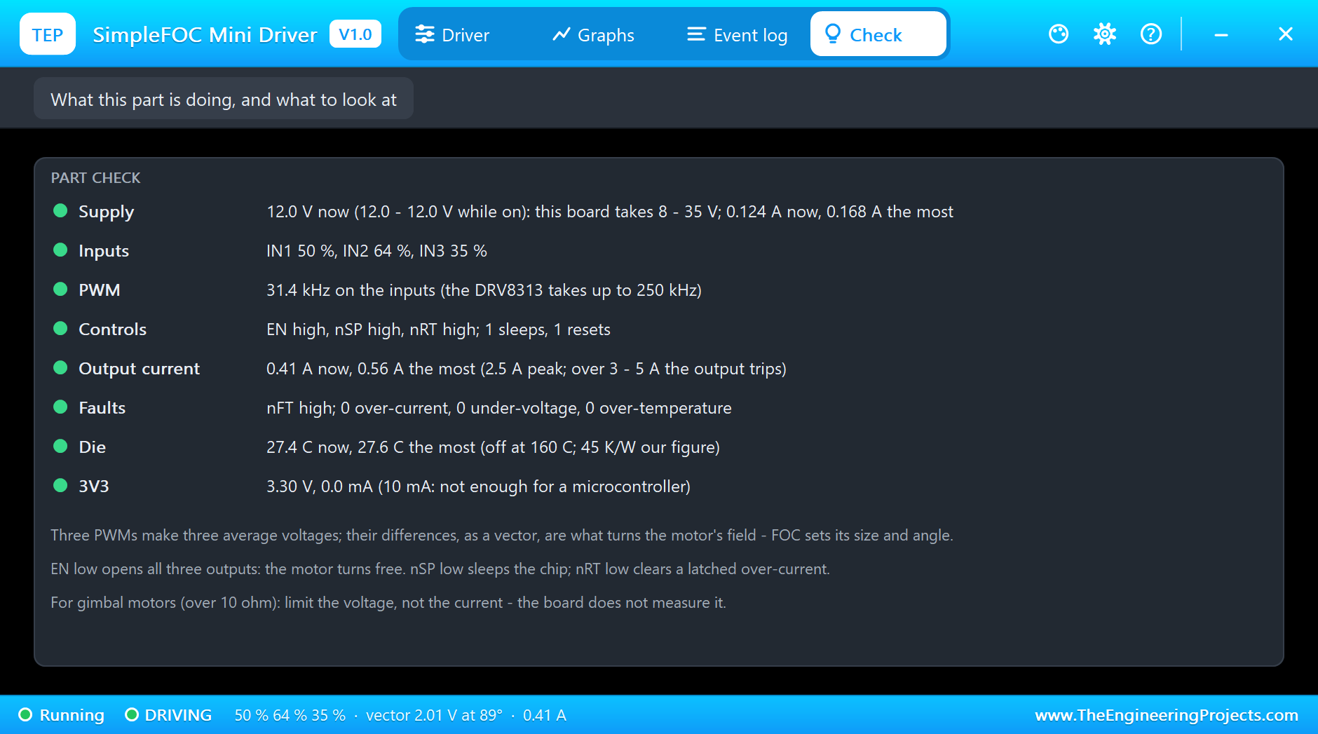
The Graphs page plots the three duties and the largest output current over the last 2, 6 or 15 simulated seconds. The duties show the sine PWM directly: slow waves during the sweep, fast ones at 2 rev/s, and flat zero while the driver sleeps or is disabled. The Event log keeps the PWM found on the inputs and every change of EN, nSP and nRT; the Check page sums up the supply, the inputs and their PWM, the controls, the output current, the faults, the die temperature and the regulator.
Try It Yourself
- Leave EN unconnected: it reads low through the chip's pull-down, and the board stays disabled.
- Raise UQ in the sketch to 3 V: the current grows by half, and the motor takes more load before it slips.
- Rename the supply terminal to +6V: under-voltage, nFT low, and the monitor prints nFT LOW (fault).
- Disconnect IN2: that output sits at V-, the vector is lopsided, and the motor runs rough.
- Type
a 90, thena -90: the field moves to each angle at 2 rev/s and holds.
Ideas to Extend the Demo
- Add a magnetic encoder on the motor's hollow shaft and close the loop: keep the vector 90 degrees ahead of the rotor (FOC).
- Read a joystick on A0 and steer the gimbal with it.
- Watch nFT in the sketch and stop the program on a fault, then reset the driver with nRT.
Your Own Sketches
The demo sketch is in the zip file, and you can change it in the Arduino IDE. New to Arduino? Start with our Arduino Tutorial for Beginners. Export the compiled binary, and set the UNO's PROGRAM property to the new file. Our guide on How to get the HEX file from Arduino shows you where the file ends up.
Things to Know Before Using a Real SimpleFOC Mini
- The 3V3 pin gives only 10 mA: enough for a pull-up or an LED, not for a microcontroller.
- Limit the voltage for gimbal motors: the board does not measure the current; the voltage you set and the winding's resistance decide it.
- Clear an over-current with nRT: toggling EN does not clear the latch; a reset pulse or a power cycle does.
- Stay within 8 to 35 V: the board's rating, though the DRV8313 itself takes more.
Troubleshooting
- DISABLED: EN is low or not connected, so all outputs are open.
- An output stays at V-: its IN pin is not connected and reads low.
- nFT low: under-voltage, a latched over-current (pull nRT low) or over-temperature.
- The motor does not follow: the vector is too small for the load, or the field turns too fast for the motor to keep up.
- The part is not simulated:
TEPSFOCMINI.DLLis missing from MODELS and from the project folder.
Limitations of the Simulation
- The outputs are averaged over each PWM period: the ripple, the 90 ns dead time and the switching delays are not simulated.
- The body diodes of open outputs and the board's capacitors are not modelled.
- The over-current trip (4 A) and the die's thermal resistance (45 K/W) are our figures within the datasheet's range.
- Arduino is a name of Arduino; this library is not made or endorsed by Arduino, Labcenter, Texas Instruments or the SimpleFOC project.
- Tested in Proteus 8.5 in November 2026 (the demo as shipped). Proteus 7 is not supported.
So, that was all about the SimpleFOC Mini Driver Library for Proteus Simulation. I hope it helps you try field-oriented control in a simulation first: three PWMs, one voltage vector, a gimbal motor that follows it, and a driver that sleeps, disables and resets like the real chip, with a pop-up that shows every switch and the vector they make. If you have any questions, ask in the comments and I will help you out. Till the next tutorial, take care and have fun!

Comments
0