


PWM Solar Charge Controller Library for Proteus Simulation


Hello friends, I hope you all are doing great. Today, I am going to share the new PWM Solar Charge Controller Library for Proteus Simulation, the next library of our renewable energy series. If you have searched for a Proteus simulation of a solar charge controller, the small box that sits between a solar panel, a battery and a load, this library brings the common 12 V / 24 V 10 A PWM controller into Proteus, with its charge stages, its pulses and its load terminals.
PWM Solar Charge Controller Library for Proteus Simulation
Latest version: V1.0 (November 2026, this tutorial)
Helping Tools
- Serial Monitor Advance: a serial terminal window for the UART of your board
- Serial Monitor Expert: the serial monitor with extra debugging tools
- LCD Library for Proteus V3.0: 16x2, 20x4 and I2C LCDs to show your readings
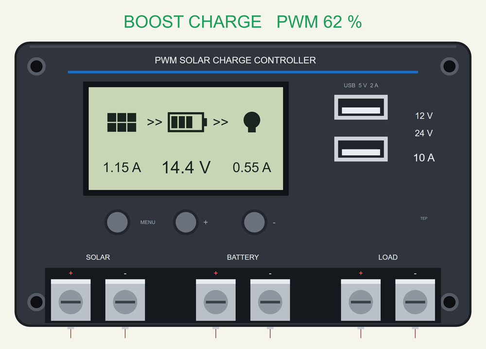
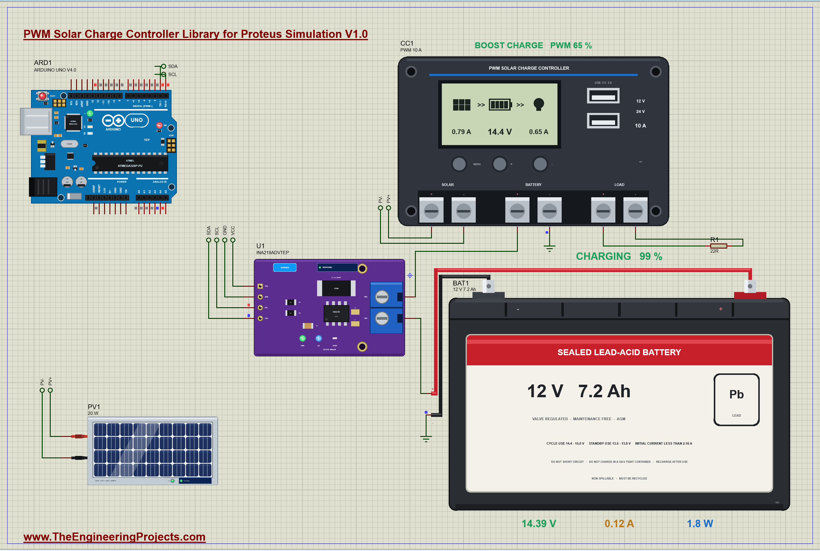
The controller is drawn at its true size, and at run time its LCD works on your sheet: the panel, the battery with its bars, the lamp, the arrows of the current and three values, with the charge stage and the PWM duty written above the case. The simulation model switches the panel for real, a hundred times a second, and holds the battery at its charge voltage by the width of the pulses. In the demo our solar panel charges our lead-acid battery through it from bulk to boost to float, while an Arduino watches the battery.
NOTICE: Our team has put a lot of effort into these small parts: the bodies, the animation and the pop-ups are all our own design, and you get them free. Your feedback is the fuel that keeps us going, so please tell us what you think in the comments below or in the Motor Driver board of our forum. And if our free libraries help you, you can buy us a coffee. So, let's get started with the PWM Solar Charge Controller Library for Proteus Simulation:
What is a PWM Solar Charge Controller?
A 12 V solar panel is not a 12 V source. Its 36 cells give about 21 V with nothing connected and about 18 V at their best point, on purpose, so that the panel can still charge a battery on a hot or hazy day. Connect such a panel straight to a 12 V battery and it works, for a while: the battery pulls the panel down to its own voltage and takes all the current the panel has. But nothing stops the charge when the battery is full, so the voltage climbs and the battery is overcharged. And at night the same wires let the battery leak back into the dark panel.
A solar charge controller is the box that solves both, and a few more problems with them. The PWM type is the simplest and the cheapest kind, and by far the most common in small systems: garden lights, a caravan, a shed, a 12 V camera on a pole. Inside is little more than a small microcontroller and two electronic switches. One switch connects the panel to the battery and the other connects the battery to the load. The controller of this library is the usual small one with an LCD and two USB ports, for 12 V and 24 V systems and 10 A.
| PWM solar charge controller, 12 V / 24 V 10 A (a maker's manual) | |
|---|---|
| System voltage | 12 V or 24 V (battery 8 to 32 V) |
| Charge and load current | 10 A each |
| Solar panel | under 50 V; the charge stops above it and resumes under 45 V |
| Boost charge | 14.4 V for 2 hours (sealed lead-acid; gel 14.2 V, flooded 14.6 V) |
| Float charge | 13.8 V |
| Boost again | when the battery falls under 13.2 V |
| Load cut for a low battery | at 11.1 V, back on at 12.6 V |
| Load cut for a high voltage | at 16 V, back on at 15 V |
| Its own consumption | 10 mA at most |
| Size and weight | 120 x 75 x 34 mm, about 130 g |
How a PWM Controller Charges a Battery
The charge runs in stages. While the battery is low, the controller simply keeps the panel's switch closed. This is the bulk stage: the panel sits straight on the battery, works at the battery's voltage and delivers all its current. The battery fills and its voltage rises.
When the battery reaches its boost voltage, 14.4 V for a sealed lead-acid battery, it is nearly full and must not go higher. Now the PWM begins. The controller opens and closes the switch many times a second, and it makes the closed part of every period just long enough that the battery stays at 14.4 V. PWM means pulse width modulation: the width of the pulses is the throttle. As the battery takes less and less, the pulses get narrower. This boost stage lasts two hours and brings the battery to a full charge.
After that the controller lowers its aim to 13.8 V, the float voltage, which a lead-acid battery can stand all day. The pulses now only replace what the load takes and what the battery loses by itself. If the battery falls under 13.2 V, because a cloud came or a big load started, the controller goes back to bulk.
The price of this simplicity is that the panel never works at its best point. In bulk it is pulled down to the battery's voltage, and a panel that could give 20 W at 17.6 V gives its current at 13 or 14 V instead. An MPPT controller, the subject of a later tutorial, converts the difference into extra current. For small panels the PWM controller is still the usual choice.
The Load Terminals and the Night
The second switch protects the battery from the other side. A lead-acid battery that is run flat is damaged for good, as we saw in our 12V Lead-Acid Battery Library for Proteus Simulation. So the load is not connected to the battery directly but to the controller's LOAD terminals, and the controller cuts the load when the battery falls to 11.1 V. It does not switch the load on again the moment the voltage recovers, because a relieved battery always springs back a little; it waits for 12.6 V, which only a charge can reach. The load terminals can also work as a light switch: on from dusk to dawn, or for some hours after dusk, with the panel as the light sensor.
And when the sun is gone, the controller opens the panel's switch and keeps it open, so the battery cannot empty itself into the panel overnight. One detail of the wiring is worth knowing before you connect a real one. In this kind of controller the three + terminals are joined inside, and both switches are in the - lines. The panel's - and the battery's - must therefore never be joined outside the controller, for example through a common ground: that would bridge the switch, and the controller could not control anything.
Features of the PWM Solar Charge Controller Library for Proteus Simulation
- The controller at true scale: the dark case, 120 x 75 mm, with the LCD, three buttons, two USB ports and six screw terminals; the LCD works at run time and the stage with the PWM duty is written above the case.
- Three charge stages: bulk, boost at 14.4 V for two hours, float at 13.8 V, and bulk again under 13.2 V, with the voltages of a maker's manual.
- Real pulses: the panel's switch opens and closes 100 times a second, and the width of the pulses holds the battery's voltage.
- The night: with no sun the switch stays open and nothing flows back into the panel.
- Load terminals: cut at 11.1 V and back at 12.6 V, cut on an overload, with three load modes: always on, dusk to dawn, hours after dusk.
- Five battery types and two system voltages: sealed, gel and flooded lead-acid, lithium-ion 3S and LiFePO4; 12 V or 24 V.
- A pop-up: the power flow from the panel to the battery and the load, the pulses, the stages, eight live values, graphs, an event log and a check page.
- A complete package: about 2.0 MB with the library, our solar panel, our lead-acid battery, our Arduino UNO V4.0 and the demo, without the source code of the model.
The PWM Solar Charge Controller in Proteus
The device is PWMCHARGECONTROLLERTEP in TEPPWMCC.LIB, under Electromechanical > Charge Controllers, with the prefix CC and the analog model TEPPWMCC.DLL. Search PWMCHARGE in Pick Devices. Its six pins are along the bottom, in the order of the real terminals: PV+ and PV- for the panel, BAT+ and BAT- for the battery, LOAD+ and LOAD- for the load. The properties are BATTERY (the battery type, B01 for sealed lead-acid), SYSTEM (12 or 24), LOADMODE (24 for always on, 0 for dusk to dawn, 1 to 23 for hours after dusk) and SPEED (the controller's clock, 1 to 7200). Our battery libraries have the same SPEED property, and the two must be set alike, so that the controller's two hours are the battery's two hours.
Download PWM Solar Charge Controller Library for Proteus Simulation
Click the button below to download PWM-Solar-Charge-Controller-Library-for-Proteus-v1.0.zip (about 2.0 MB, without the source code of the models):
PWM Solar Charge Controller Library for Proteus V1.0- README.txt: installation, the demo, the wiring, troubleshooting and the limits of the simulation.
- Proteus Library Files:
TEPPWMCC.LIB,TEPSOLAR.LIB,TEPLEADACID.LIBandArduinoV4TEP.LIB. - Proteus Model Files:
TEPPWMCC.DLL,TEPSOLAR.DLL,TEPLEADACID.DLLandTEPARDUINO.DLL. - Arduino Code: the demo sketch.
- Proteus Simulation: the demo project, its HEX file and copies of the DLLs.
No Proteus yet? Read How to Download and Install Proteus 7 and 8. New to libraries? Follow How to Install a New Library in Proteus.
How to Install PWM Solar Charge Controller Library for Proteus Simulation
- Close Proteus and extract the whole zip file, for example to your Desktop.
- Copy the files from Proteus Library Files into the LIBRARY folder of Proteus.
- Copy the files from Proteus Model Files into the MODELS folder.
- Delete
TEPPWMCC.IDXfrom the LIBRARY folder if it is there. - The demo also uses our INA219 Current Sensor Library for Proteus: install it from its own package (it is not in this zip).
- Start Proteus, press P and search for PWMCHARGE.
Proteus Simulation of a Solar Charging System with Arduino
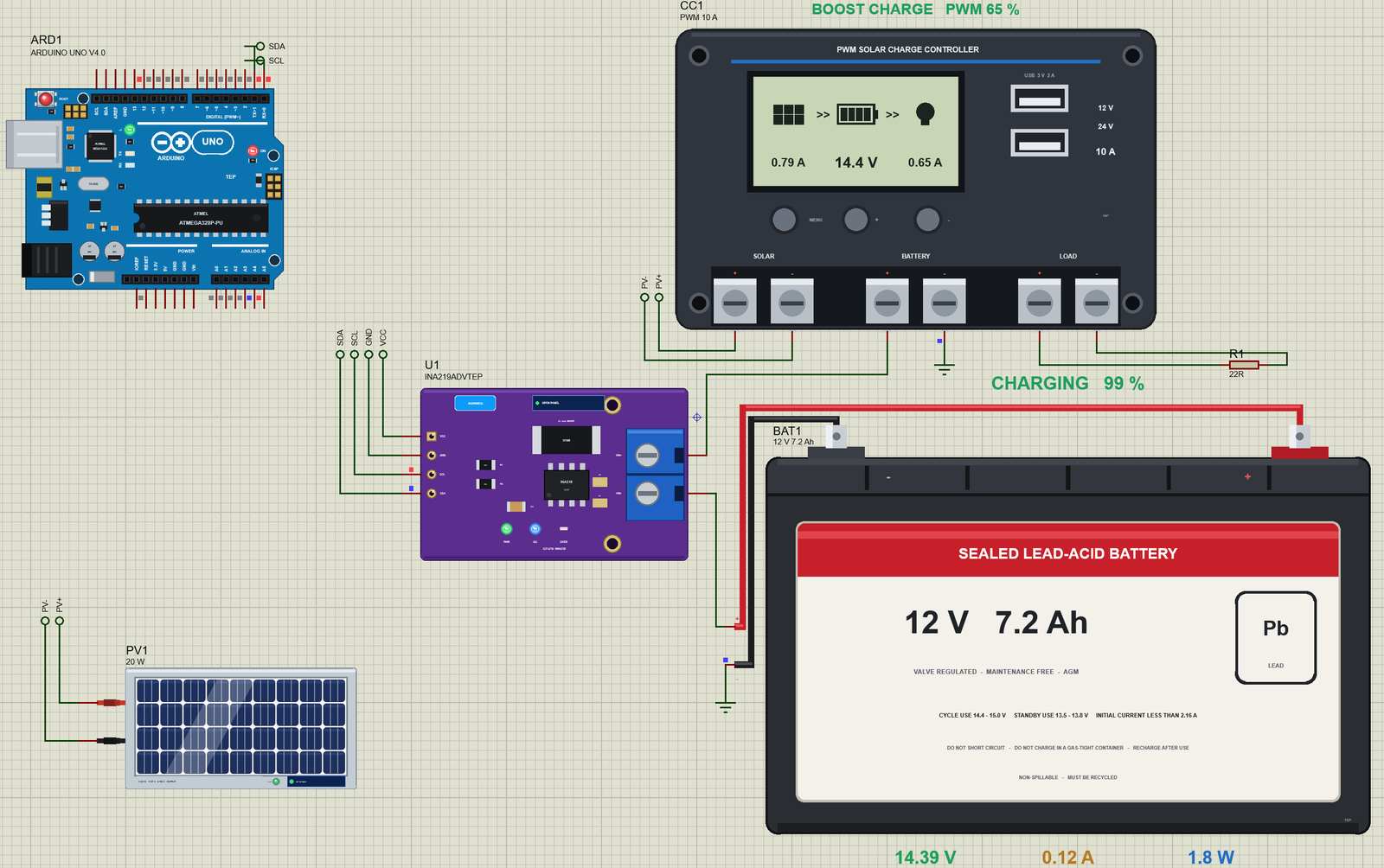
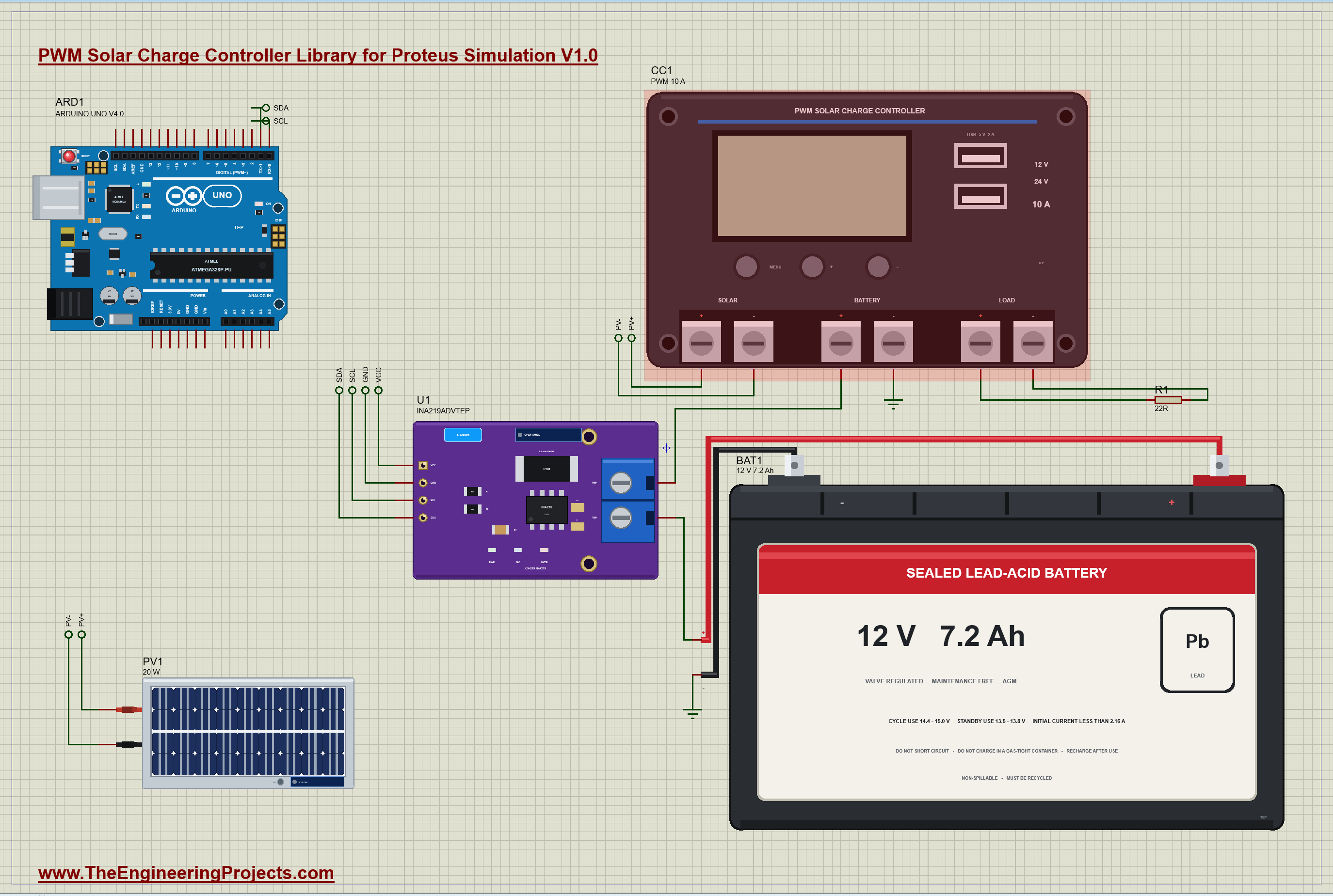
The demo is a complete small solar system on an A3 sheet, built from four of our libraries, with our Arduino UNO Library for Proteus V4.0 and its built-in monitor, the same window as our TEP Serial Monitor Advance for Proteus, as the battery monitor. The panel, PV1, is the 20 W panel of our 12V Solar Panel Library for Proteus in full sun. Its + and - go to the controller's PV+ and PV- terminals over two labels. The controller, CC1, is set for a sealed lead-acid battery (B01) in a 12 V system, with the load always on. Its BAT+ terminal goes through the 0.1 ohm shunt of our INA219 (U1, its pop-up version) to the + of the battery, BAT1, the 12 V 7.2 Ah battery of the lead-acid library, which starts three quarters full. The battery's - and the controller's BAT- are on ground. A 22 ohm resistor, R1, on the LOAD terminals stands for a 12 V lamp of about 7 W. The SPEED of the battery and of the controller is 3600, so one simulated second is an hour. Open PWM-Solar-Charge-Controller-Battery-INA219-ArduinoUnoV4.pdsprj.
The Sketch
The Arduino does not control anything here; the controller does its work alone. The sketch is a battery monitor, the kind of add-on many people build for their solar system. The INA219 sits between the controller and the battery, so it sees the battery's current in both directions. There is one difficulty: a PWM controller charges in pulses, and a single reading can catch the current high or low. The sketch therefore takes 32 readings, 1.25 ms apart, which spans four of the controller's pulses, and works with their mean:
    sumV += ((uint16_t)readReg(0x02) >> 3) * 0.004;              // 4 mV a step: the bus, the battery's + terminal
    sumI += readReg(0x01) * 0.00001 / SHUNT_OHM;                 // 10 uV a step, signed: + into the battery
    while (micros() - at < 1250) { }                             // 1.25 ms apart: 32 readings span four pulses
From the mean voltage and current alone it can tell what the controller is doing:
  if (amps < -0.03) return F("the battery feeds the load");
  if (volts >= 14.25) return F("boost charge");
  if (volts >= 13.60 && volts < 14.00 && amps < 0.15) return F("float charge");
  if (amps > 0.03) return F("bulk charge");
And it counts the amp-hours that go into the battery. The constant CLOCK is 3600, the same as the SPEED of the battery and the controller; in real life it would be 1:
if (lastAt) ampHours += (amps + lastAmps) / 2 * (now - lastAt) / 1000.0 * CLOCK / 3600.0; // the amp-hour counterThe LED on pin 13 lights while the battery is being charged. You can type reset to set the amp-hours back to 0 or rate 1000 to report once a second.
PWM Solar Charge Controller Simulation Results
Open the project and press Run. The demo runs about 7 simulated seconds, which are seven hours of a sunny day for the battery; with the pop-ups open and the pictures being taken it took a little over two minutes on our PC. Click the controller for its pop-up. Every number below comes from one simulation run, the demo exactly as it ships.
Bulk: the Panel Straight on the Battery
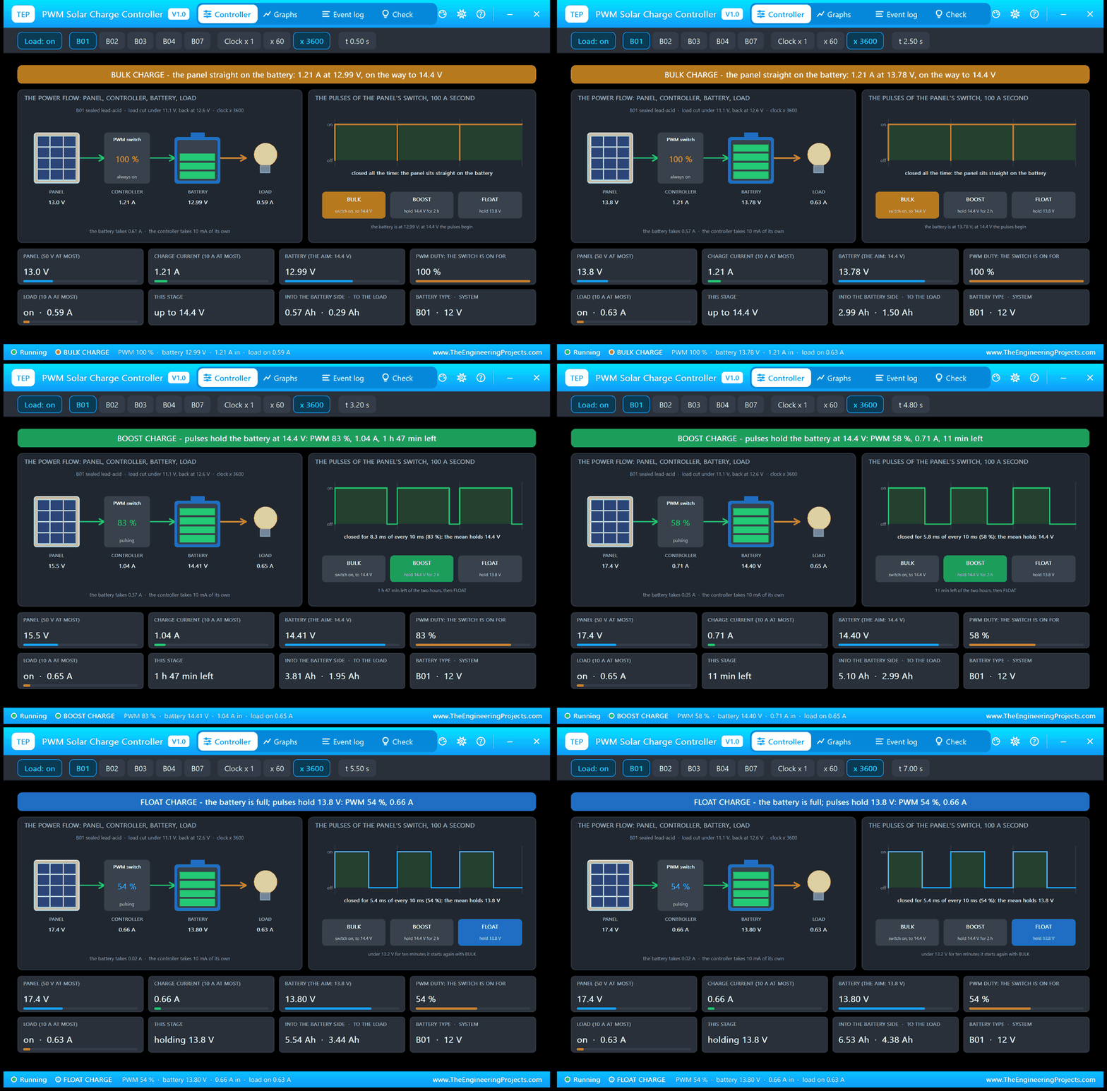
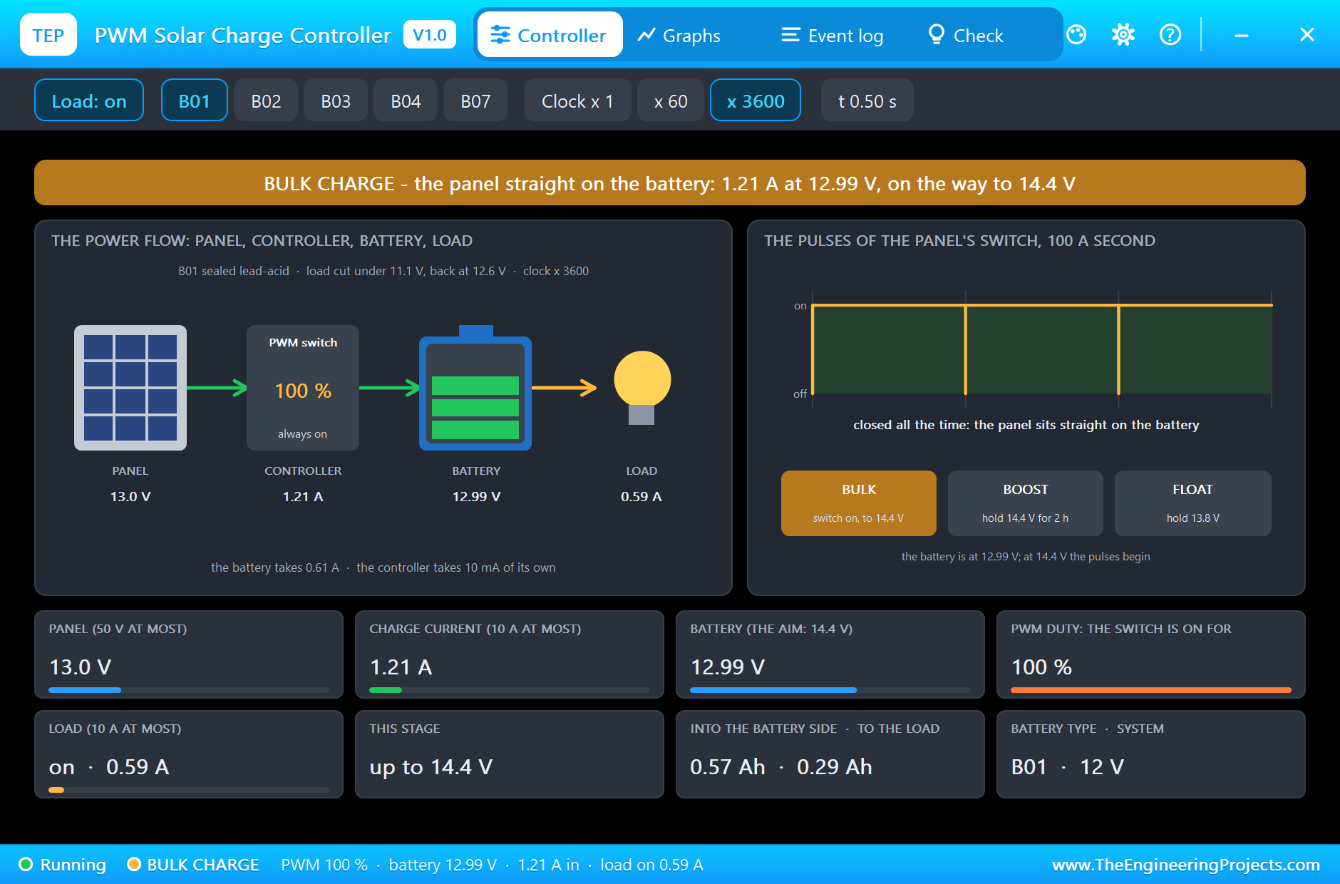
After 30 ms the controller has seen the panel's open voltage and closes its switch. The Event log notes BULK CHARGE with the battery at 12.53 V. At 0.5 s the pop-up shows the power flow: 1.21 A from the panel through the switch, 0.59 A on to the lamp, and the battery takes the rest, 0.61 A. The switch is closed all the time, PWM 100 %, and the panel is held at the battery's voltage, 13.0 V. On the right the three stages are drawn with the one now lit, and above them three periods of the switch.
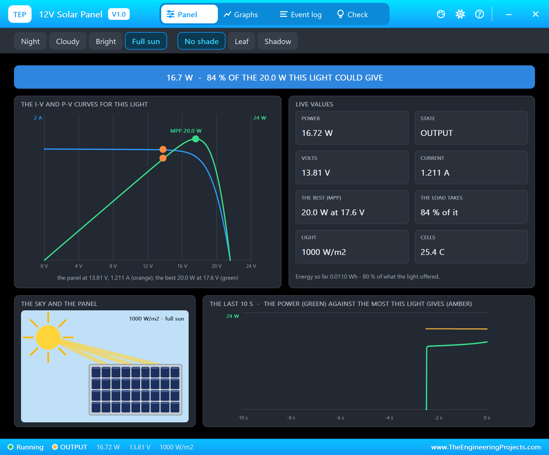
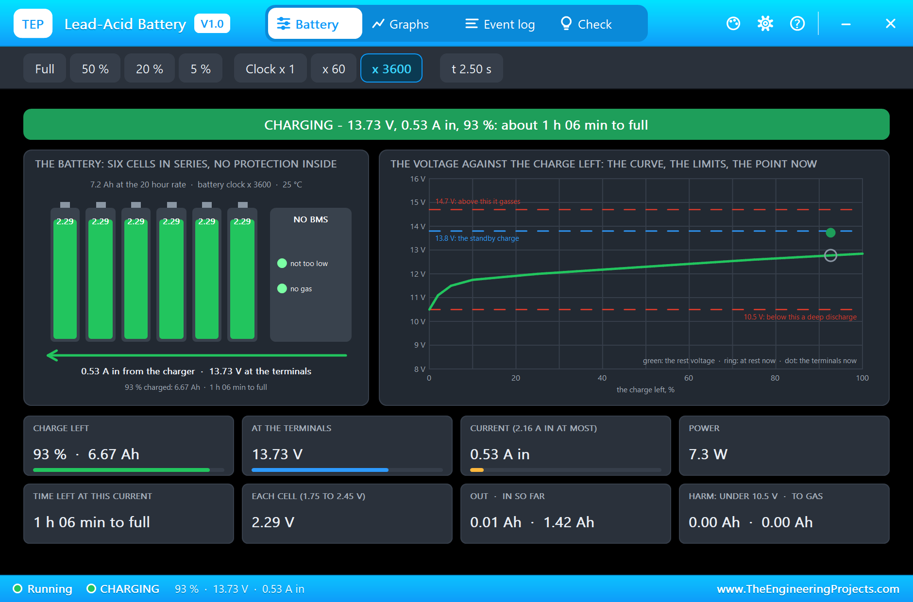
Our solar panel's pop-up shows what that means for the panel. At 2.5 s it works at 13.81 V and 1.211 A, 16.72 W, although this light could give 20.0 W at 17.6 V: the battery, not the panel, decides the voltage. The panel gives 84 % of what it could. That is the nature of a PWM controller. The battery's own pop-up, taken at the same moment, shows 0.53 A going in at 13.73 V with 93 % of the charge.
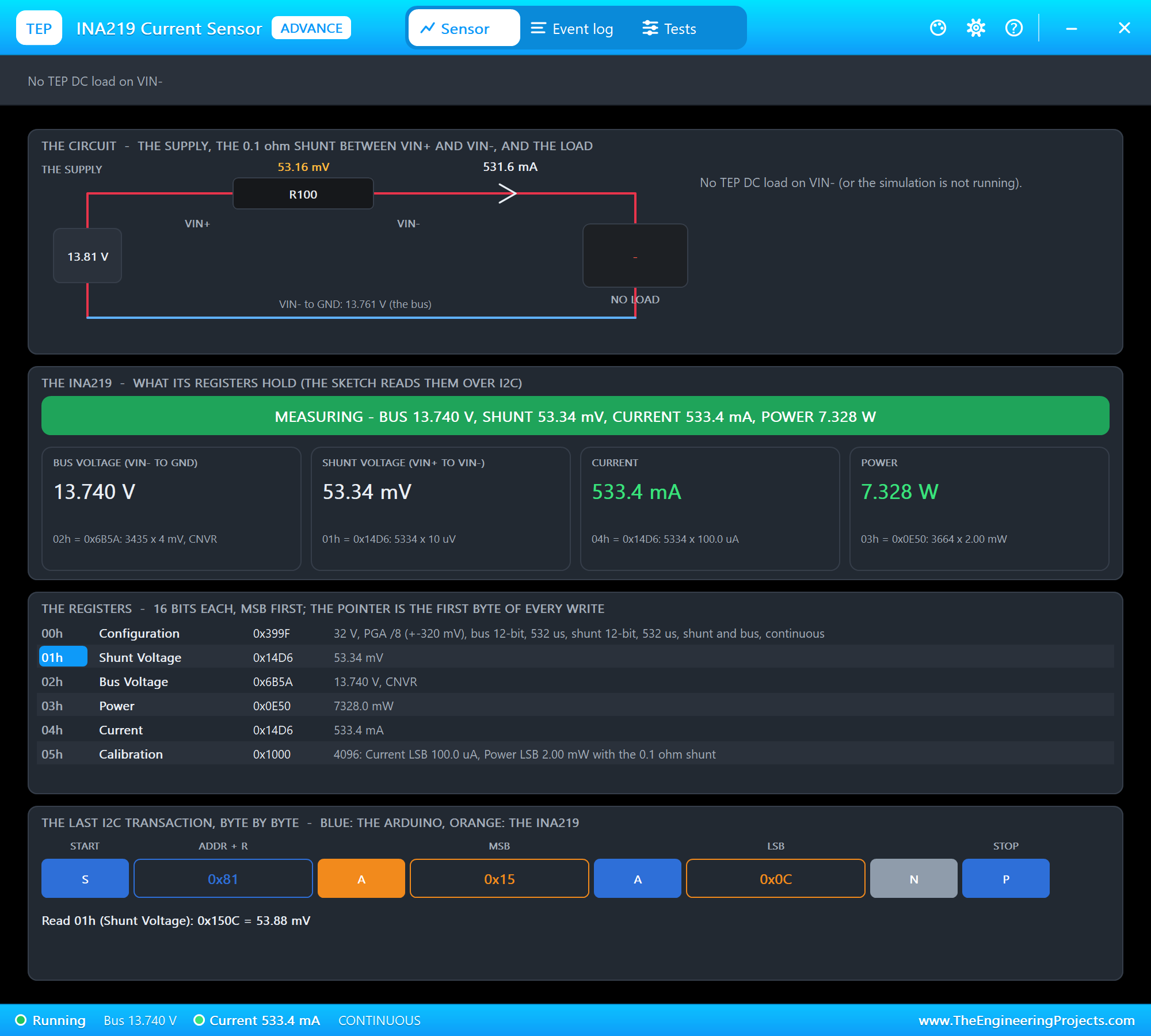
The INA219 between the controller and the battery reads 13.740 V on the bus, 53.34 mV across the shunt and 533.4 mA into the battery.
Boost: the Pulses Begin
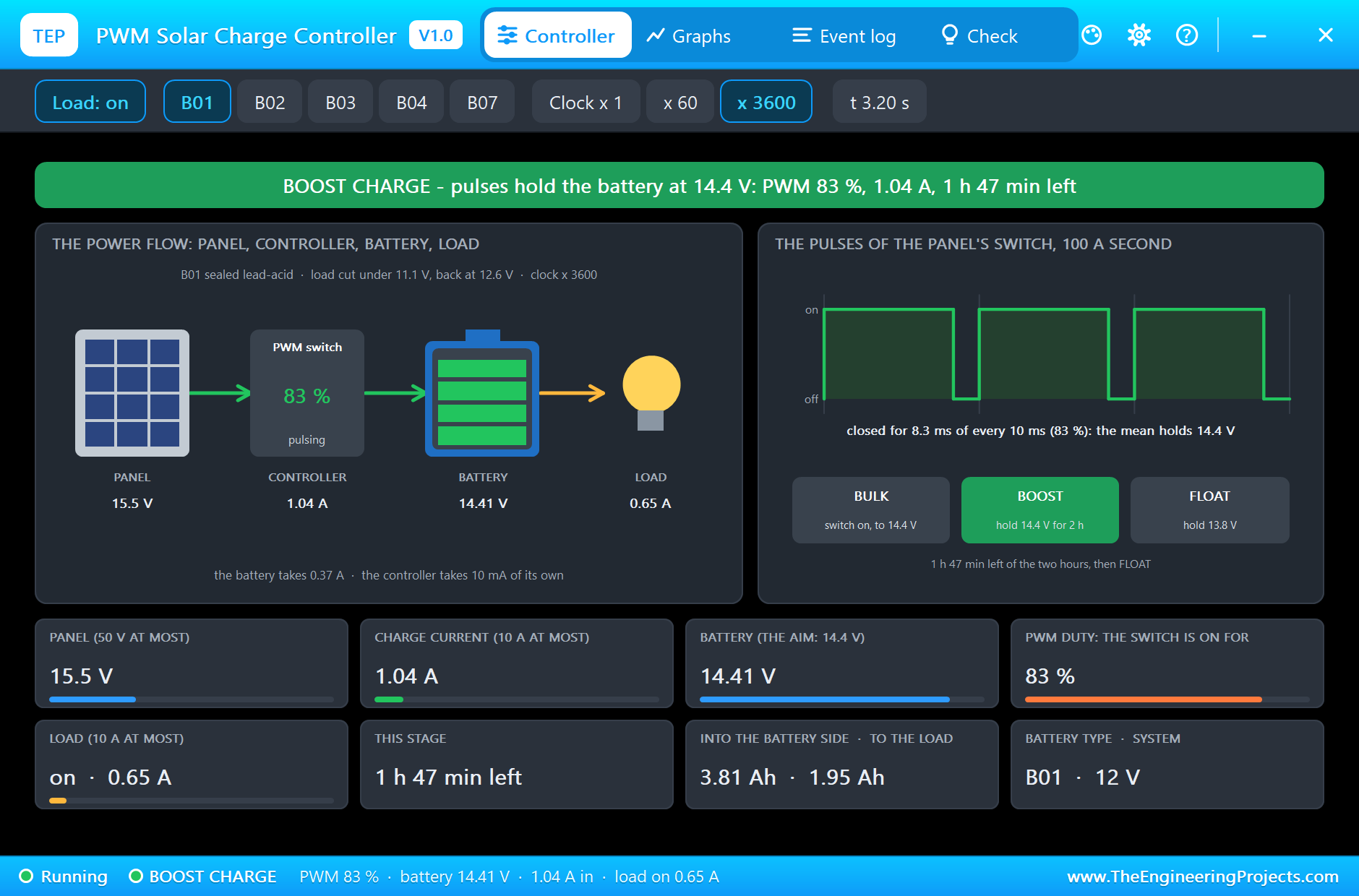
At 3.000 s the battery reaches 14.4 V and the log writes BOOST CHARGE. From now on the switch pulses. At 3.2 s it is closed for 83 % of every period and the battery sits at 14.41 V; the mean charge current has come down to 1.04 A. On the sheet the stage and the duty are written above the controller, and its LCD shows the arrows from the panel to the battery and on to the lamp, with the charge current, the battery voltage and the load current under them.
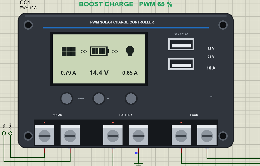
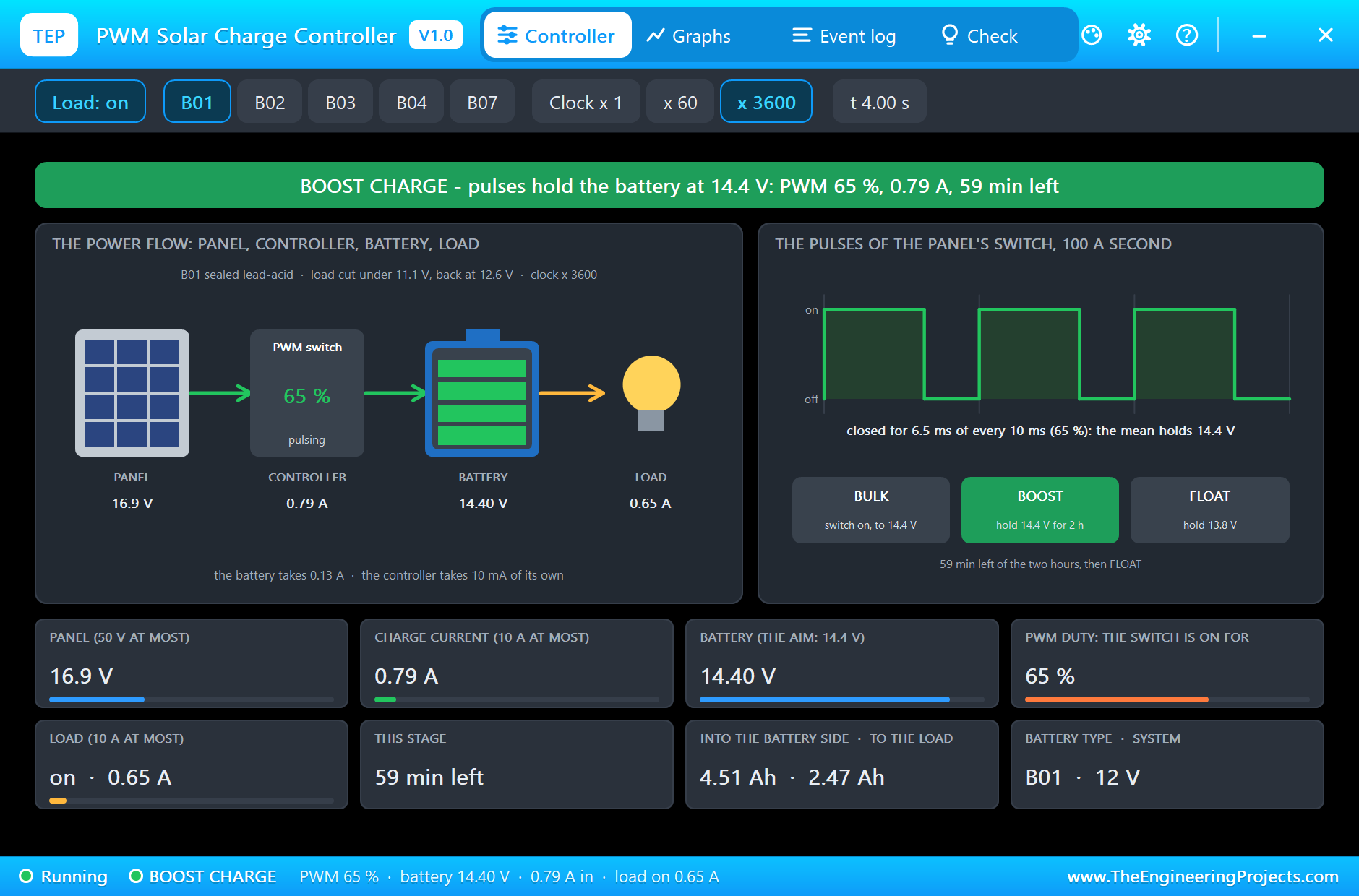
At 4.0 s, an hour into the boost stage, the pulses are narrower: 65 %, 6.5 ms of every 10 ms. The battery is held at 14.40 V, 0.79 A comes from the panel on average, the lamp takes 0.65 A, and only 0.13 A still goes into the battery, which is nearly full. The panel's mean voltage has risen to 16.9 V, because between the pulses the panel is open and stands at its open voltage. The banner counts down the two hours: 59 minutes left.
Float: the Battery is Full
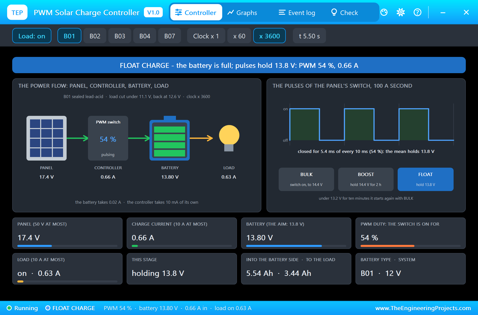
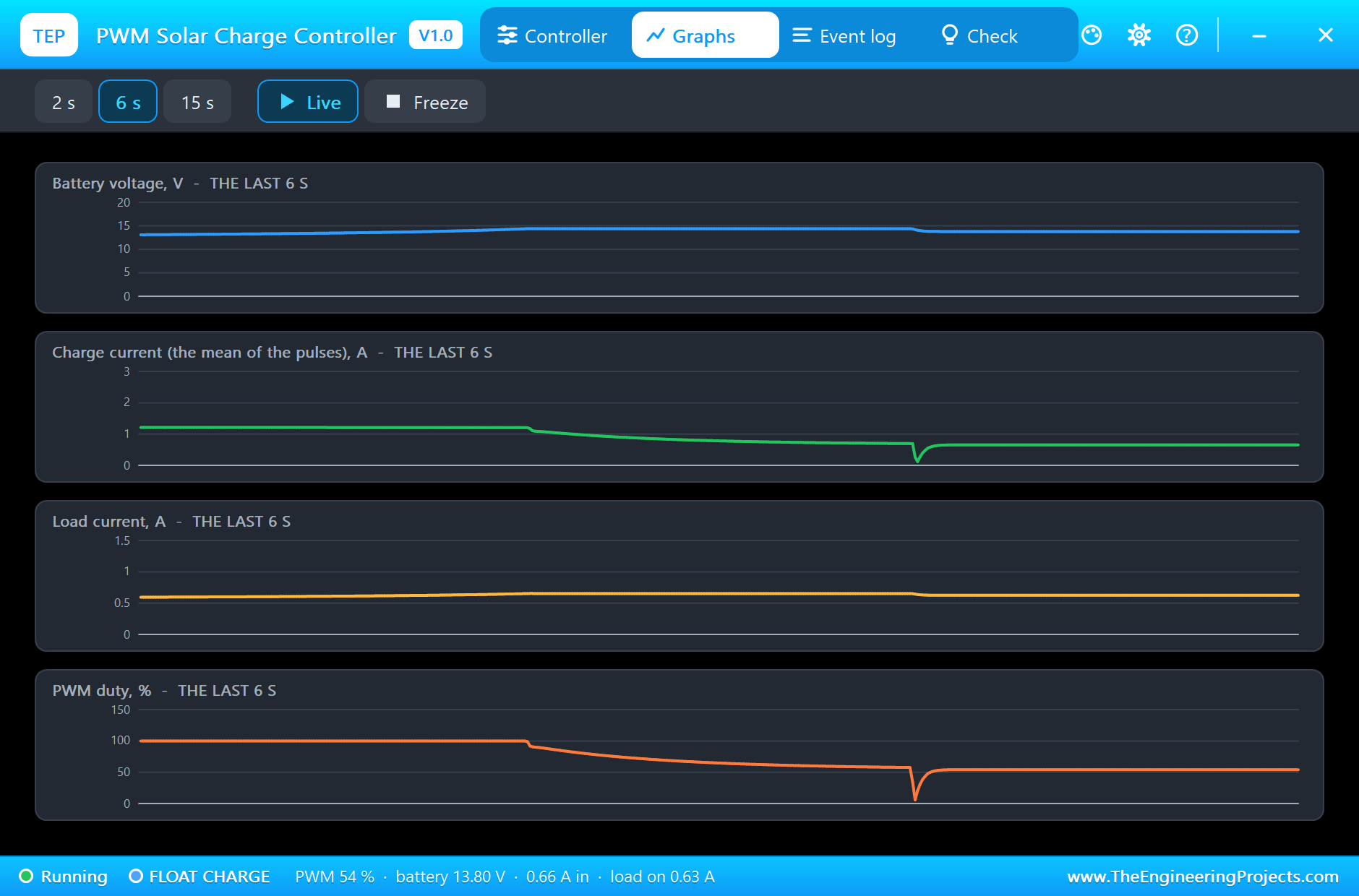
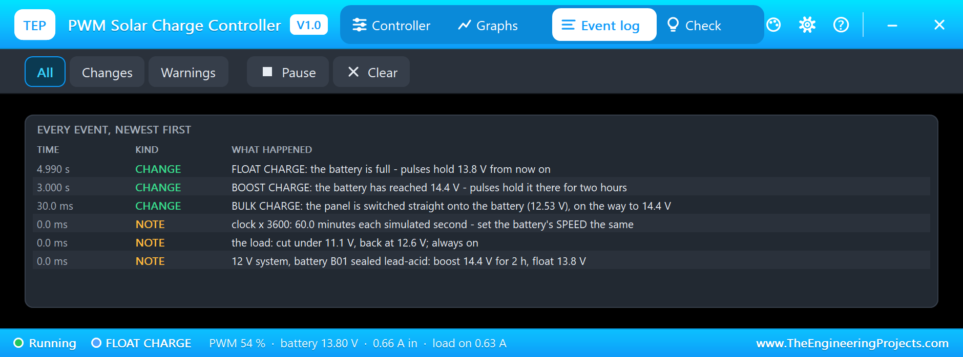
At 4.990 s the two hours are over and the log writes FLOAT CHARGE. The controller lowers its aim to 13.8 V. For a moment the switch stays open, until the lamp has pulled the battery down to that voltage, and then the pulses come back. At 5.5 s the controller holds 13.80 V with a duty of 54 %: 0.66 A from the panel, of which the lamp takes 0.63 A. The battery itself now takes almost nothing. As long as the sun shines, the panel feeds the lamp and the battery stays full.
A Night: the Load Cut
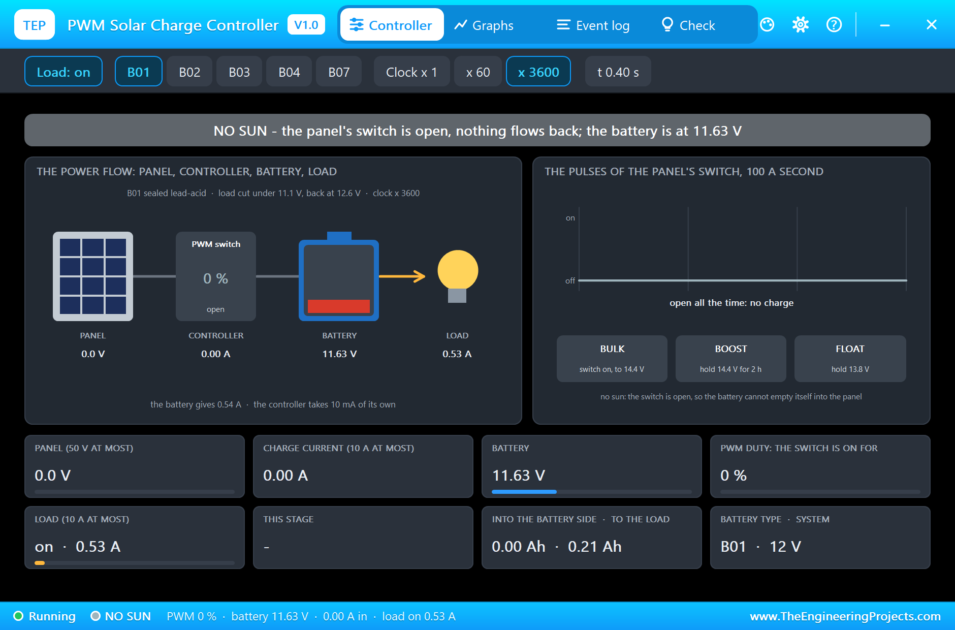
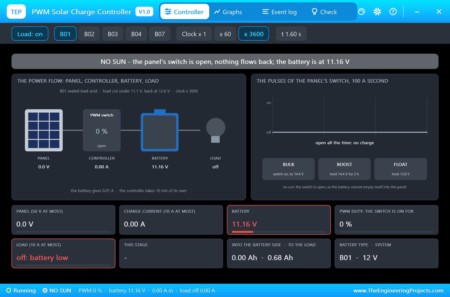
The demo is a sunny day. For a second simulation run we took the sun away and started with a nearly empty battery: IRRADIANCE 0 on the panel and SOC 12 on the battery. Now the controller shows NO SUN: its switch stays open, and nothing flows back into the dark panel. The battery alone feeds the lamp, 0.53 A at 11.63 V at 0.4 s. An hour later the battery is at its limit. At 1.320 s the log writes LOAD CUT, the battery down to 11.09 V, and the controller switches the lamp off. Relieved, the battery springs back a little, to 11.16 V, but the lamp stays off: the controller waits for 12.6 V, and only a charge can bring that. The battery has been saved from a deep discharge, which is exactly what its own library showed happening without a controller.
The Graphs, the Event Log and the Check Page
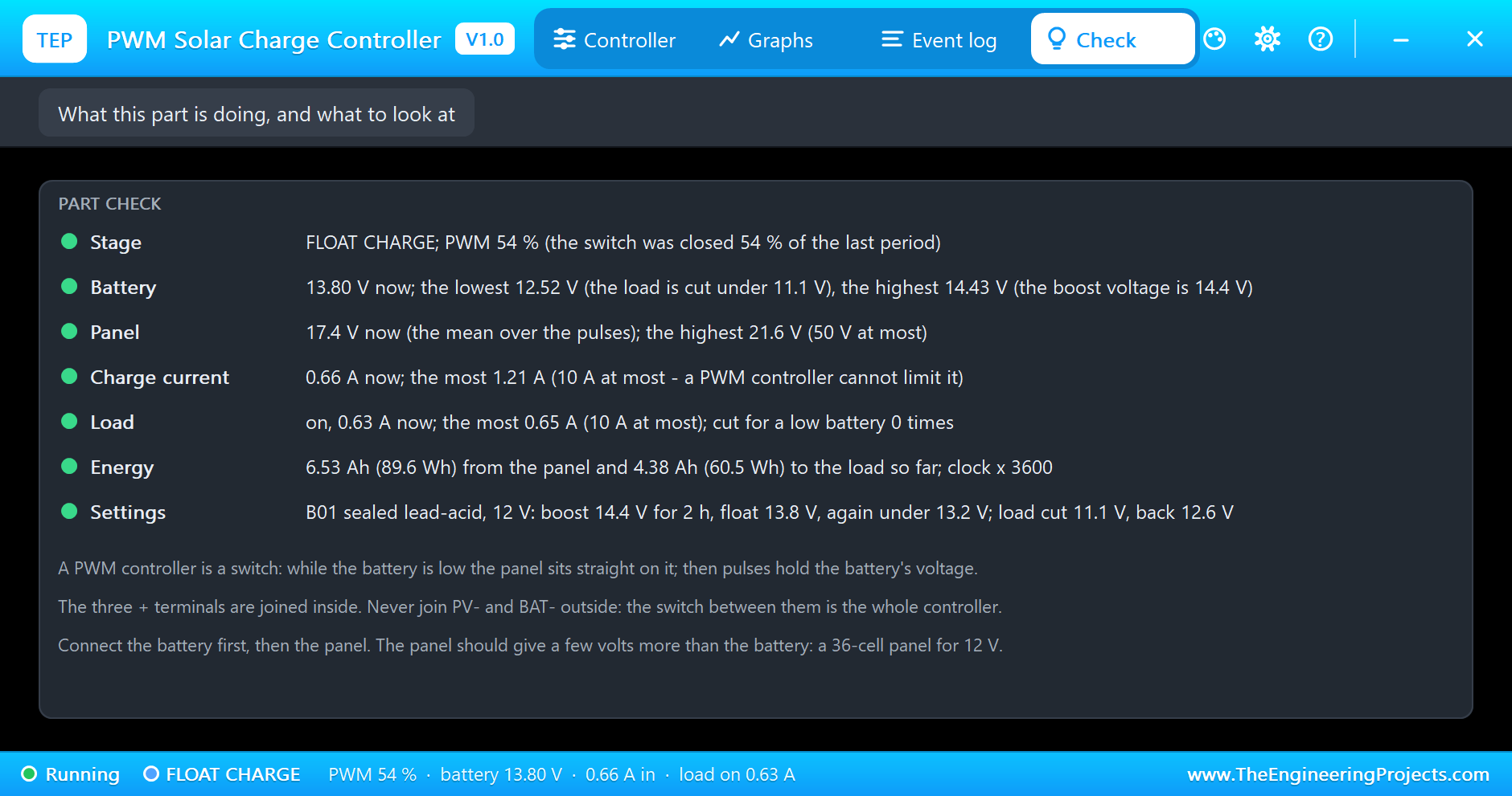
Back to the sunny day. The Graphs page plots the battery voltage, the mean charge current, the load current and the PWM duty over the last 2, 6 or 15 simulated seconds: the duty at 100 % through the bulk stage, falling through the boost stage, a short dip to zero at the change to float, and steady after it. The Event log keeps every change of the stage and every warning. The Check page sums up the run: 6.53 Ah (89.6 Wh) from the panel and 4.38 Ah (60.5 Wh) to the load, 12.52 V as the battery's lowest voltage and 14.43 V as its highest, 21.6 V as the panel's highest, its open voltage between the pulses.
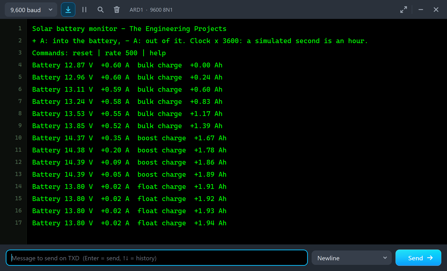
The monitor tells the same day from the Arduino's side, a line for every half hour. It names the stages from the battery's voltage and current alone: bulk charge up to 13.85 V, boost charge at 14.37 to 14.39 V with a current that falls to 0.05 A, then float charge at 13.80 V. Its counter ends at +1.94 Ah into the battery.
Try It Yourself
- Click Cloudy in the solar panel's pop-up during the float stage: the pulses widen, and when the panel cannot hold 13.8 V any more the battery helps the lamp.
- Click Night in the panel's pop-up: the controller shows NO SUN, its switch opens and the battery feeds the lamp alone.
- Click Load: on in the controller's pop-up to switch the lamp off, as the button of the real controller does, and watch the duty fall.
- Set LOADMODE to 0 and run again: the lamp stays off by day and comes on a minute after the sun is gone.
- Set the panel's WATTS to 50: the bulk stage is over much sooner, and in the boost stage the pulses are narrower.
- Set IRRADIANCE to 0 and the battery's SOC to 12 for our second run: the night and the load cut.
Ideas to Extend the Demo
- Add a second INA219 at address 0x41 in the LOAD line and let the sketch print the panel's share and the load's share of the current.
- Replace the lead-acid battery by the battery of our 12V LiFePO4 Battery Library for Proteus Simulation and set BATTERY to B07: a two-step charge up to 14.4 V.
- Show the stage, the battery voltage and the amp-hours of the day on an LCD.
Your Own Sketches
The demo sketch is in the zip file, and you can change it in the Arduino IDE. New to Arduino? Start with our Arduino Tutorial for Beginners. Export the compiled binary, and set the UNO's PROGRAM property to the new file. Our guide on How to get the HEX file from Arduino shows you where the file ends up.
Things to Know Before Using a Real PWM Solar Charge Controller
- Connect the battery first: the controller is powered by the battery and reads the system voltage from it. Then the panel, then the load; the other way round when you take it apart.
- Match the panel to the battery: a 36-cell panel for a 12 V battery, 72 cells for 24 V. More volts are simply lost in a PWM controller, and over 50 V the charge stops.
- Mind the current: a PWM controller cannot limit the charge current, so the panel's short-circuit current must stay under the controller's 10 A.
- Keep the minus lines apart: the + terminals are common in this kind of controller; never join PV- and BAT- outside it, and check how your own controller is built.
- Big loads go on the battery: an inverter or a motor that starts with a surge belongs on the battery through a fuse, not on the LOAD terminals.
Troubleshooting
- NO SUN although the panel is lit: PV- is joined to BAT- or to ground outside the controller, or the panel's open voltage is not a volt above the battery.
- NO BATTERY: under 8 V on BAT+ and BAT-. The controller needs a battery to work; a panel alone is not enough.
- The load is off: the battery fell under 11.1 V and is not back at 12.6 V yet, the load mode waits for the night, or there was an overload.
- The stage never leaves bulk: the panel is too small for the load, or the two-hour clock runs in real time. Set SPEED like the battery's, 60 or 3600.
- A meter on the panel reads an odd voltage: between the battery's voltage and the panel's open voltage. It shows the mean of the pulses.
- The part is not simulated:
TEPPWMCC.DLLis missing from MODELS and from the project folder.
Limitations of the Simulation
- The stages, their voltages and times, the load cut and its return, the high-voltage cut, the panel's limit and the controller's own current are from a maker's manual of a 12 V / 24 V PWM controller.
- Our own figures: 100 pulses a second, the resistances of the two switches, the overload levels, the delays, and the wiring with the three + terminals joined; controllers with a common minus exist as well.
- The pulses are real on the panel's side. At the battery terminals the model smooths them to a ripple of some tens of millivolts, as the plates of a real battery do.
- Not modelled: the USB ports (drawn only), the menus of the buttons (the properties and the pop-up set everything), the temperature compensation and the controller's heat.
- Arduino is a name of Arduino; this library is not made or endorsed by Arduino, Labcenter or any maker of charge controllers.
- Tested in Proteus 8.5 in November 2026 (the demo as shipped). Proteus 7 is not supported.
So, that was all about the PWM Solar Charge Controller Library for Proteus Simulation. I hope it helps you plan a small solar system in a simulation before you buy the parts: a panel, a controller that charges in bulk, boost and float, a battery that is neither overcharged nor run flat, and an Arduino that watches it all. If you have any questions, ask in the comments and I will help you out. Till the next tutorial, take care and have fun!

Comments
0