


MT3608 DC-DC Boost Converter Module Library for Proteus Simulation


Hello friends, I hope you all are doing great. Today, I am going to share the new MT3608 DC-DC Boost Converter Module Library for Proteus Simulation, one more library of our renewable energy series. If you have searched for a Proteus simulation of the small blue step-up module that makes 5 V, 9 V or 12 V out of a single Li-ion cell, this library brings it into Proteus: set the trimmer's voltage, connect a source and a load, and watch what the higher voltage costs.
MT3608 DC-DC Boost Converter Module Library for Proteus Simulation
Latest version: V1.0 (November 2026, this tutorial)
Helping Tools
- Serial Monitor Advance: a serial terminal window for the UART of your board
- Serial Monitor Expert: the serial monitor with extra debugging tools
- LCD Library for Proteus V3.0: 16x2, 20x4 and I2C LCDs to show your readings
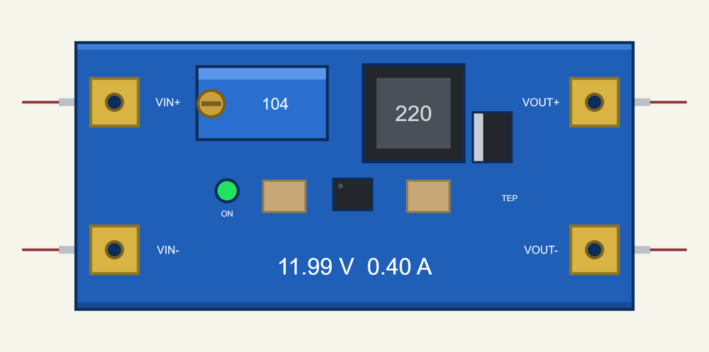
The module is drawn at its true size, small beside an Arduino UNO. At run time a lamp on the board shows its state and a line shows the volts and amps of the output. The simulation model keeps the power balance of a real converter: the input current follows from the load and from the losses in the inductor, the switch and the diode, so the efficiency, the current limit and the heat of the chip all come out of it.
NOTICE: Our team has put a lot of effort into these small parts: the bodies, the animation and the pop-ups are all our own design, and you get them free. Your feedback is the fuel that keeps us going, so please tell us what you think in the comments below or in the Motor Driver board of our forum. And if our free libraries help you, you can buy us a coffee. So, let's get started with the MT3608 DC-DC Boost Converter Module Library for Proteus Simulation:
What is a Boost Converter?
A boost converter, or step-up converter, makes a higher DC voltage from a lower one. It needs only four parts: an inductor, a fast switch, a diode and a capacitor. The switch closes and the current in the inductor grows; the switch opens and the inductor, which does not let its current stop, pushes it through the diode into the output, at whatever voltage that takes. The longer the switch stays closed in each period (the duty), the higher the output: roughly Vout = Vin / (1 - duty).
There is one rule that no converter can escape: it gives a higher voltage, never more power. What the output delivers, the input must supply, plus the losses. So the input current is the output current times the voltage ratio, and a little more. 0.4 A at 12 V from a 3.7 V cell costs about 1.5 A from that cell, and the lower the cell's voltage falls, the more current the same load costs.
The MT3608 is a small chip that holds the switch and the control loop of such a converter. The well-known blue module adds the inductor, the diode, two capacitors and a multi-turn trimmer with which you set the output voltage. It is the usual way to run a 5 V, 9 V or 12 V load from a single Li-ion cell or a small solar panel.
| The module of this library (the chip's data sheet and the module's parts) | |
|---|---|
| Input | 2 to 24 V; the chip starts at 2 V |
| Output | up to 28 V, set with the trimmer; never under the input |
| Switch | inside the chip: 80 milliohm, limited at 4 A; 1.2 MHz |
| Trimmer | 100 k over 2.2 k: Vout = 0.6 V x (1 + R / 2.2 k) |
| On the board | a 22 uH inductor and an SS34 Schottky diode |
| Size | 36 x 17 mm; four pads: IN+, IN-, OUT+, OUT- |
Features of the MT3608 DC-DC Boost Converter Module Library for Proteus Simulation
- A small part at its true size: the blue board with its trimmer, inductor, diode and chip, seen from above, about half as long as an Arduino UNO.
- Any output from 2 to 28 V: the VOUT property is what the trimmer is turned to; chips in the pop-up set 5, 9, 12 or 24 V while the simulation runs.
- A real power balance: the input current follows from the load and the losses, so a weak source sags and a draining battery is worked harder.
- The efficiency comes out of the model: four losses are counted, in the inductor, the switch, the diode and in switching.
- The limits of the chip: the 4 A current limit, the start at 2 V and the thermal switch-off.
- The pass-through path: with the chip off the input still reaches the output through the inductor and the diode, as on the real module.
- Live on the sheet: a lamp for the state and the output's volts and amps on the board.
- A pop-up: where the power goes, the current in the inductor over two switching periods, eight live values, graphs, an event log and a check page.
- A complete package: about 1.6 MB with the library, our 18650 cell, our Arduino UNO V4.0 and the demo, without the source code of the model.
The MT3608 Module in Proteus
The device is MT3608BOOSTTEP in TEPMT3608.LIB, under Analog ICs > Regulators, with the prefix PS and the model TEPMT3608.DLL. Search MT3608 or BOOST in Pick Devices. It has four pins: IN+ and IN- on the left, OUT+ and OUT- on the right; IN- and OUT- are one ground, as on the real board. The properties are VOUT, the voltage the trimmer is set to (2 to 28 V, 12 by default), and TEMP, the temperature of the air around the module.
The model is a mean-value one: it does not switch at 1.2 MHz in the simulation, which would make every run crawl. It holds the set voltage and takes the input current that the power balance asks for. That keeps the simulation fast and still shows everything that matters around the module. In the demo it works together with the cell of our 18650 Li-ion Battery Library for Proteus Simulation.
Download MT3608 DC-DC Boost Converter Module Library for Proteus Simulation
Click the button below to download MT3608-DC-DC-Boost-Converter-Module-Library-for-Proteus-v1.0.zip (about 1.6 MB, without the source code of the models):
MT3608 DC-DC Boost Converter Module Library for Proteus V1.0- README.txt: installation, the demo, the wiring, troubleshooting and the limits of the simulation.
- Proteus Library Files:
TEPMT3608.LIB,TEP18650.LIBandArduinoV4TEP.LIB. - Proteus Model Files:
TEPMT3608.DLL,TEP18650.DLLandTEPARDUINO.DLL. - Arduino Code: the demo sketch.
- Proteus Simulation: the demo project, its HEX file and copies of the DLLs.
No Proteus yet? Read How to Download and Install Proteus 7 and 8. New to libraries? Follow How to Install a New Library in Proteus.
How to Install MT3608 DC-DC Boost Converter Module Library for Proteus Simulation
- Close Proteus and extract the whole zip file, for example to your Desktop.
- Copy the files from Proteus Library Files into the LIBRARY folder of Proteus.
- Copy the files from Proteus Model Files into the MODELS folder.
- Delete
TEPMT3608.IDXfrom the LIBRARY folder if it is there. - Start Proteus, press P and search for MT3608.
Proteus Simulation of a 12 V Supply from One Li-ion Cell
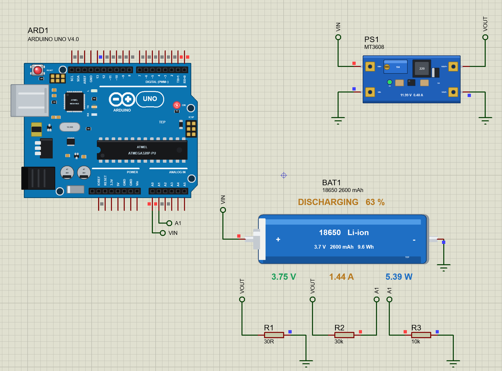
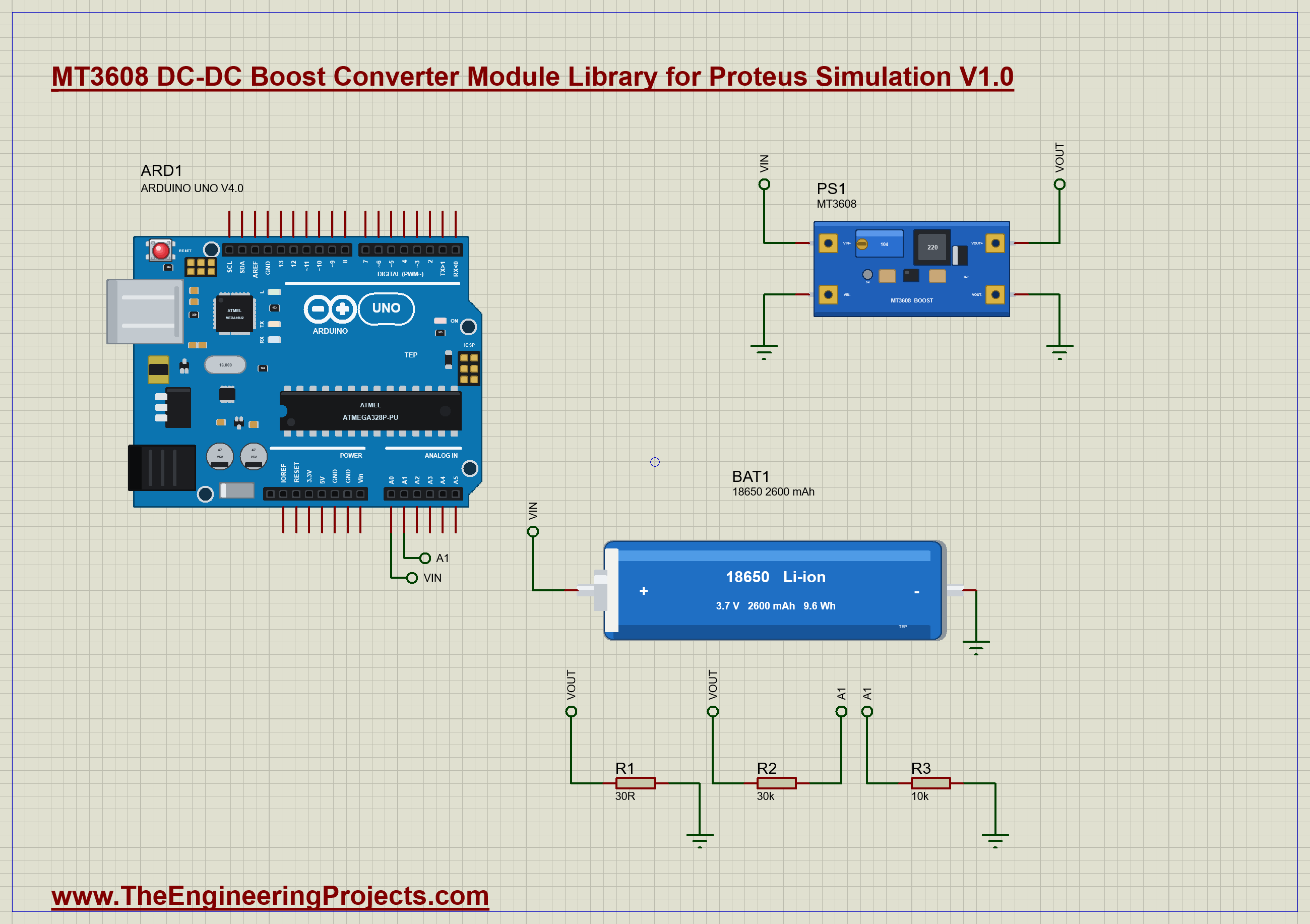
The demo makes 12 V from a single Li-ion cell and watches what that costs the cell. The module, PS1, has its VOUT property at 12. Its IN+ pin goes to the + end of BAT1, the cell of our 18650 Li-ion Battery Library for Proteus Simulation, through the label VIN; IN- and OUT- are on ground. OUT+ feeds the label VOUT, and there hangs the load: R1, a resistor of 30 ohm, which takes 0.4 A and 4.8 W at 12 V. Two more resistors, R2 of 30k and R3 of 10k, bring a quarter of the output to the analog input A1 of our Arduino UNO Library for Proteus V4.0; the cell's voltage goes straight to A0. The cell starts 90 percent charged, and its battery clock of 600 turns every simulated second into ten minutes, so a whole discharge fits into ten seconds. The Arduino's built-in monitor is the same window as our TEP Serial Monitor Advance for Proteus. Open MT3608-Boost-Converter-18650-ArduinoUnoV4.pdsprj.
The Sketch
The sketch is a monitor: it only measures. Three numbers describe the hardware around it, the divider on the output, the load and the voltage at which the cell counts as low:
const float DIVIDER = 4.0;                     // 30 k over 10 k: the output arrives as a quarter
const float LOAD_OHMS = 30.0;
const float LOW_CELL = 3.5;                    // V under load: about a quarter of the charge is left
Each voltage is the mean of eight readings of the converter:
float volts(byte pin) {                        // eight readings averaged
  long sum = 0;
  for (byte k = 0; k < 8; k++) sum += analogRead(pin);
  return sum / 8.0 * (5.0 / 1023.0);
}
The load is a known resistor, so the output voltage alone gives the current and the power:
  const float vin = volts(PIN_IN), vout = volts(PIN_OUT) * DIVIDER;
  const float amps = vout / LOAD_OHMS, watts = vout * amps;
Four times a second the sketch prints a line and ends it with a verdict. The LED on pin 13 lights together with LOW BATTERY: time to stop.
Serial.println(vout < 0.9 * 12.0 ? F("OUTPUT LOW") : low ? F("LOW BATTERY") : F("ok"));You can type rate 1000 to report once a second.
MT3608 Boost Converter Simulation Results
Open the project and press Run. The demo runs 10 simulated seconds, which are 100 minutes for the cell; with the pop-ups open and the pictures being taken it took 142 seconds on our PC. Click the module for its pop-up. Every number below comes from one simulation run, the demo exactly as it ships.
12 V from a Full Cell
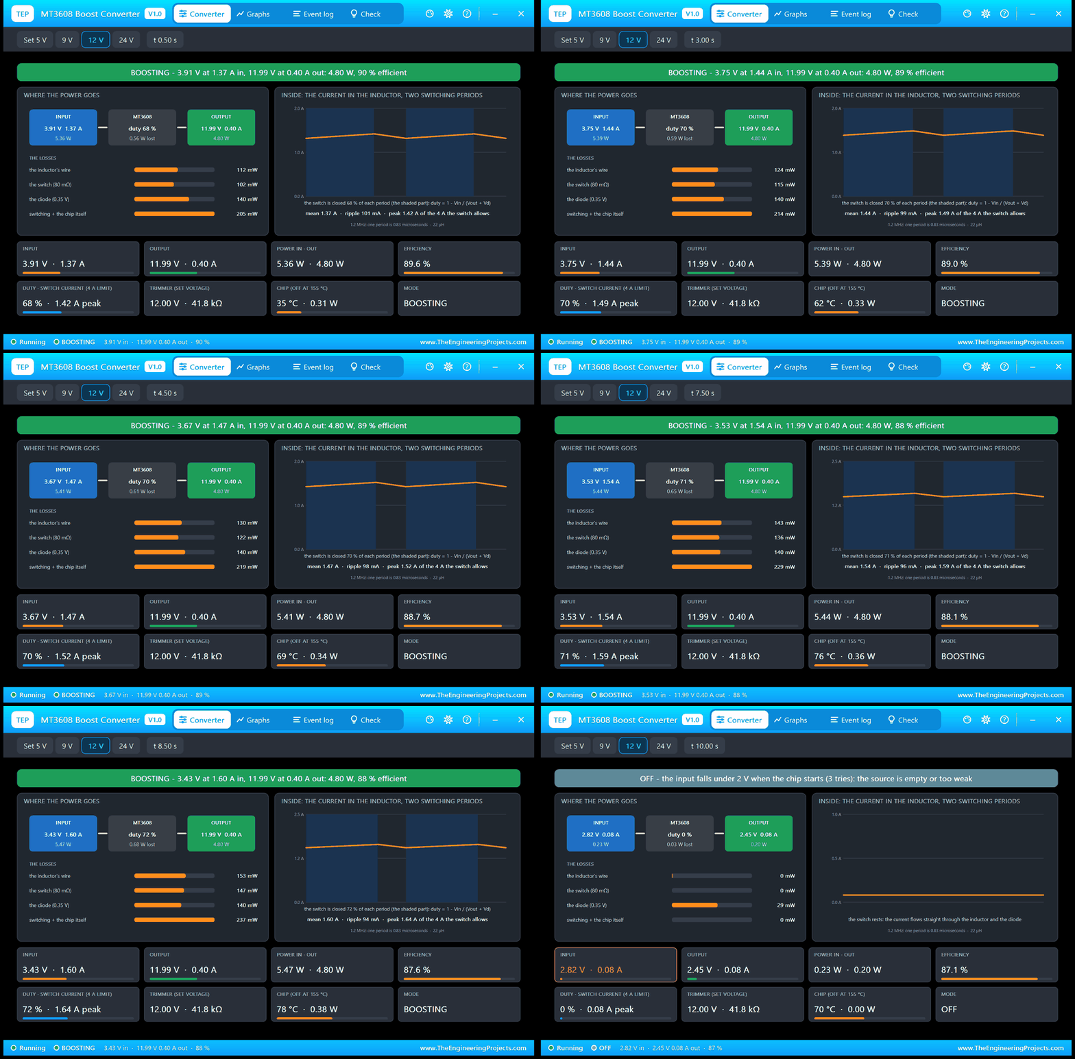
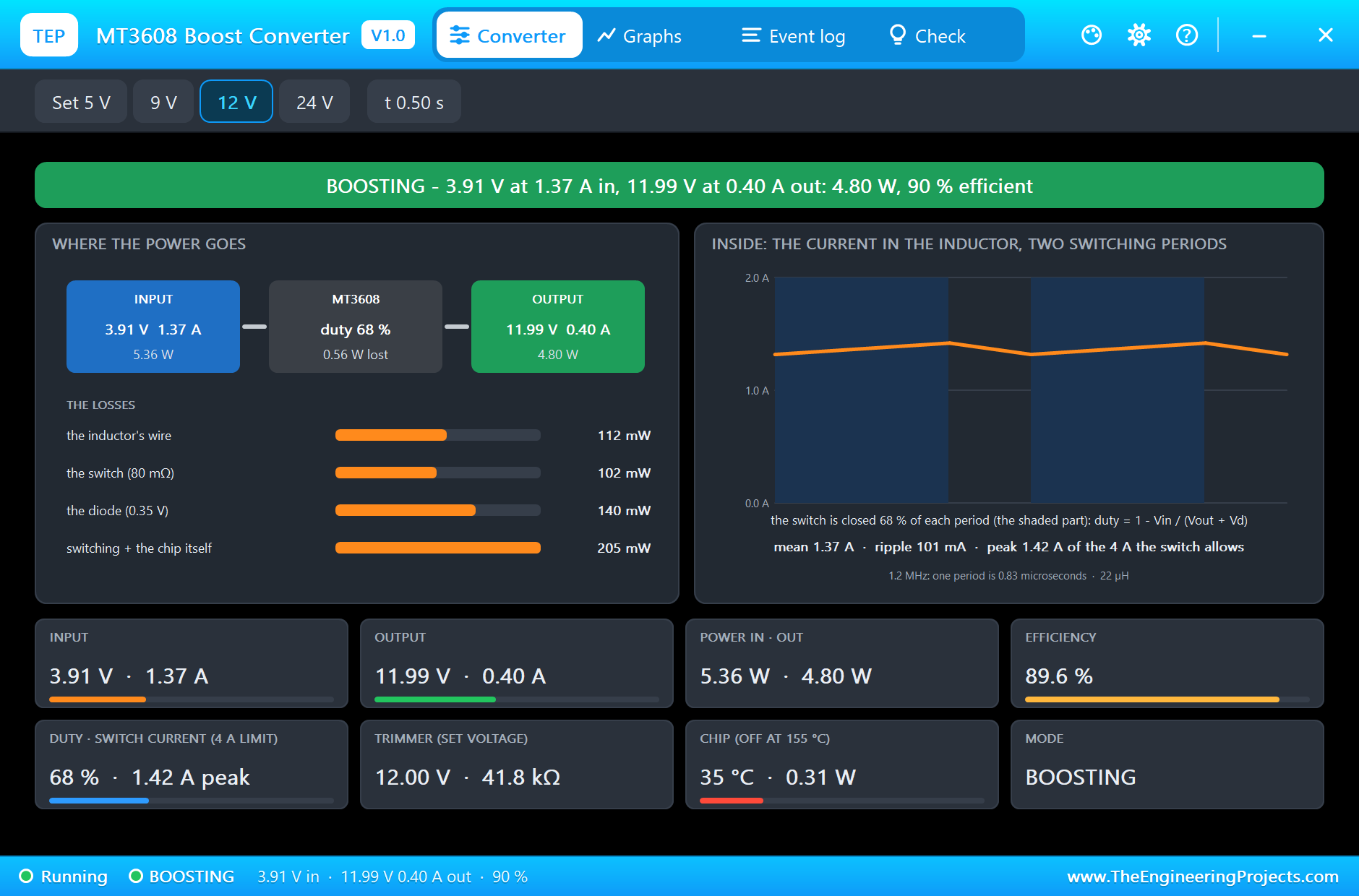
Half a second after the start the cell gives 3.91 V and the banner is green: BOOSTING. The left card shows where the power goes: 5.36 W come in, 3.91 V at 1.37 A, and 4.80 W go out, 11.99 V at 0.40 A. That is 89.6 percent; the other 0.56 W stay in the module, and the four bars tell where: 112 mW in the wire of the inductor, 102 mW in the switch, 140 mW in the diode and 205 mW in switching. Look at the two currents: the load takes 0.40 A, the cell must give 1.37 A. That is the price of the higher voltage.
The right card looks inside. It shows the current in the inductor over two switching periods: it climbs while the switch is closed, the shaded part, and falls while the diode feeds the output. The switch is closed 68 percent of each period, and the current swings 101 mA around its mean, up to a peak of 1.42 A, far from the 4 A the switch allows. The chip is at 35 degrees.
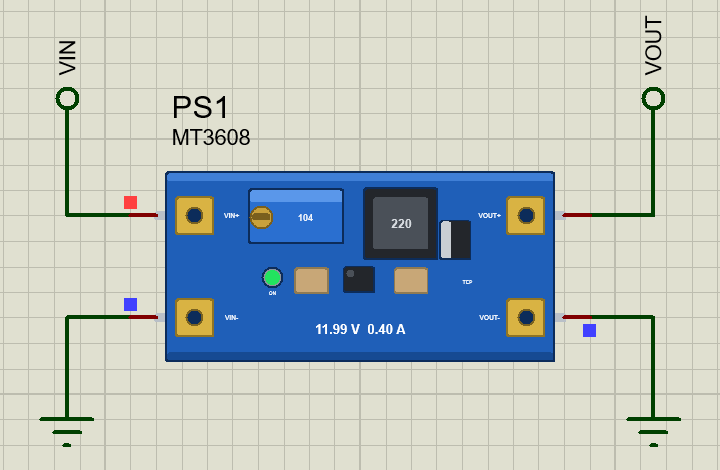
On the sheet the lamp of the module is green and the board shows 11.99 V and 0.40 A. The cell beside it tells its own state.
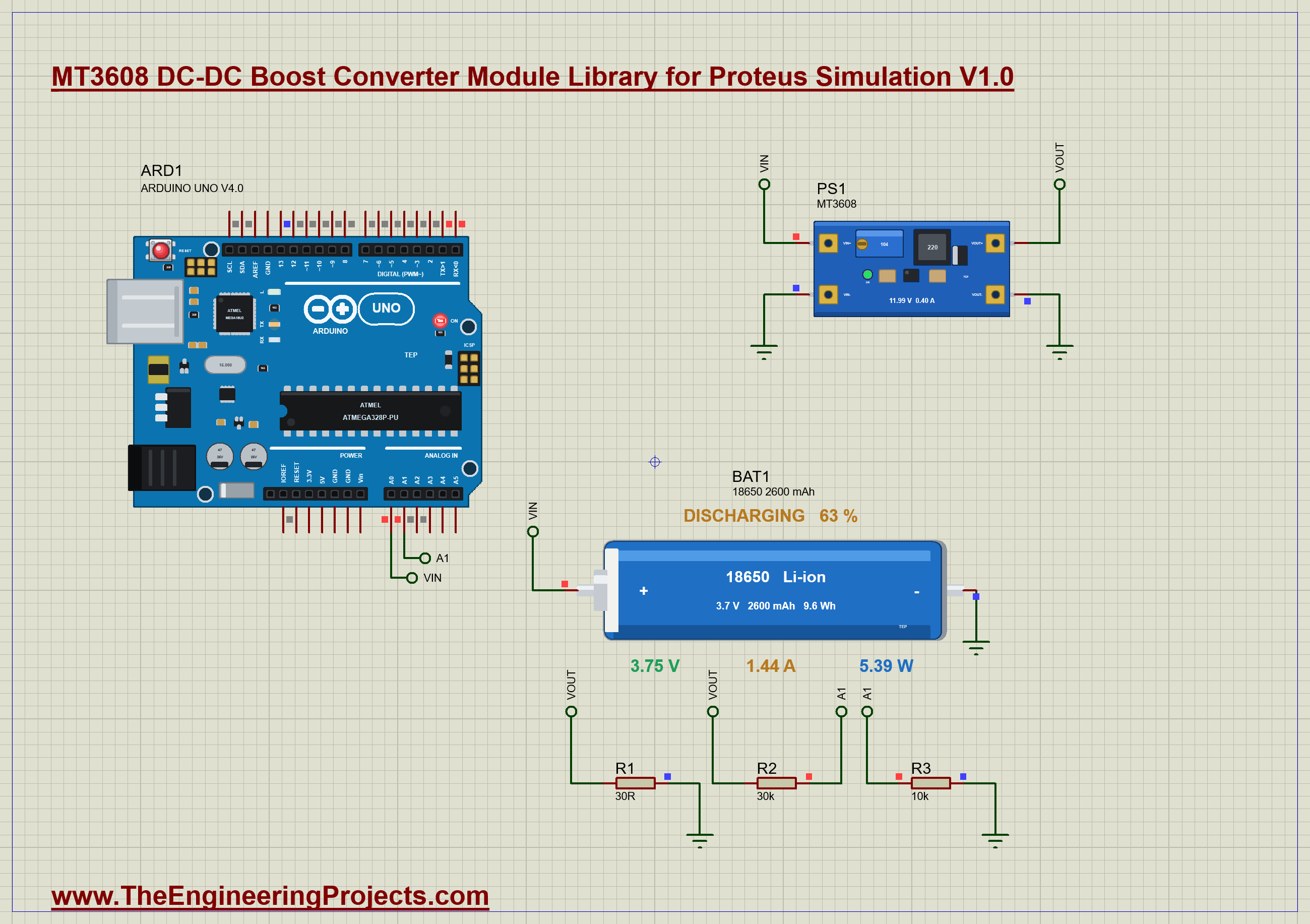
The Cell Drains, the Input Current Grows
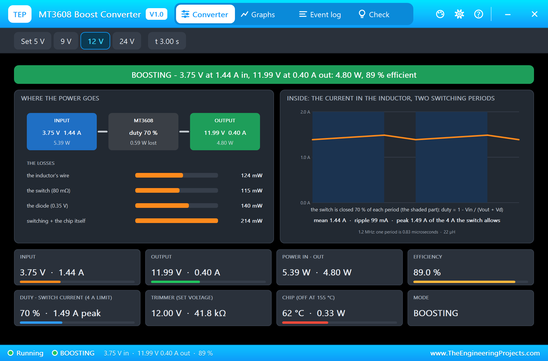
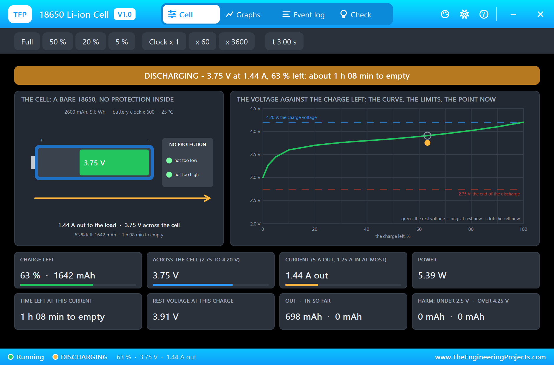
After 3 seconds, half an hour for the cell, the cell is down to 3.75 V. The output has not moved: 11.99 V at 0.40 A. But the same 4.80 W now cost 1.44 A, and the efficiency has slipped to 89.0 percent. The chip has warmed up to 62 degrees.
The cell has a pop-up of its own. At the same moment it shows 63 percent left, 1642 mAh, and works out that at this current it will be empty in 1 hour and 8 minutes.
Low Battery
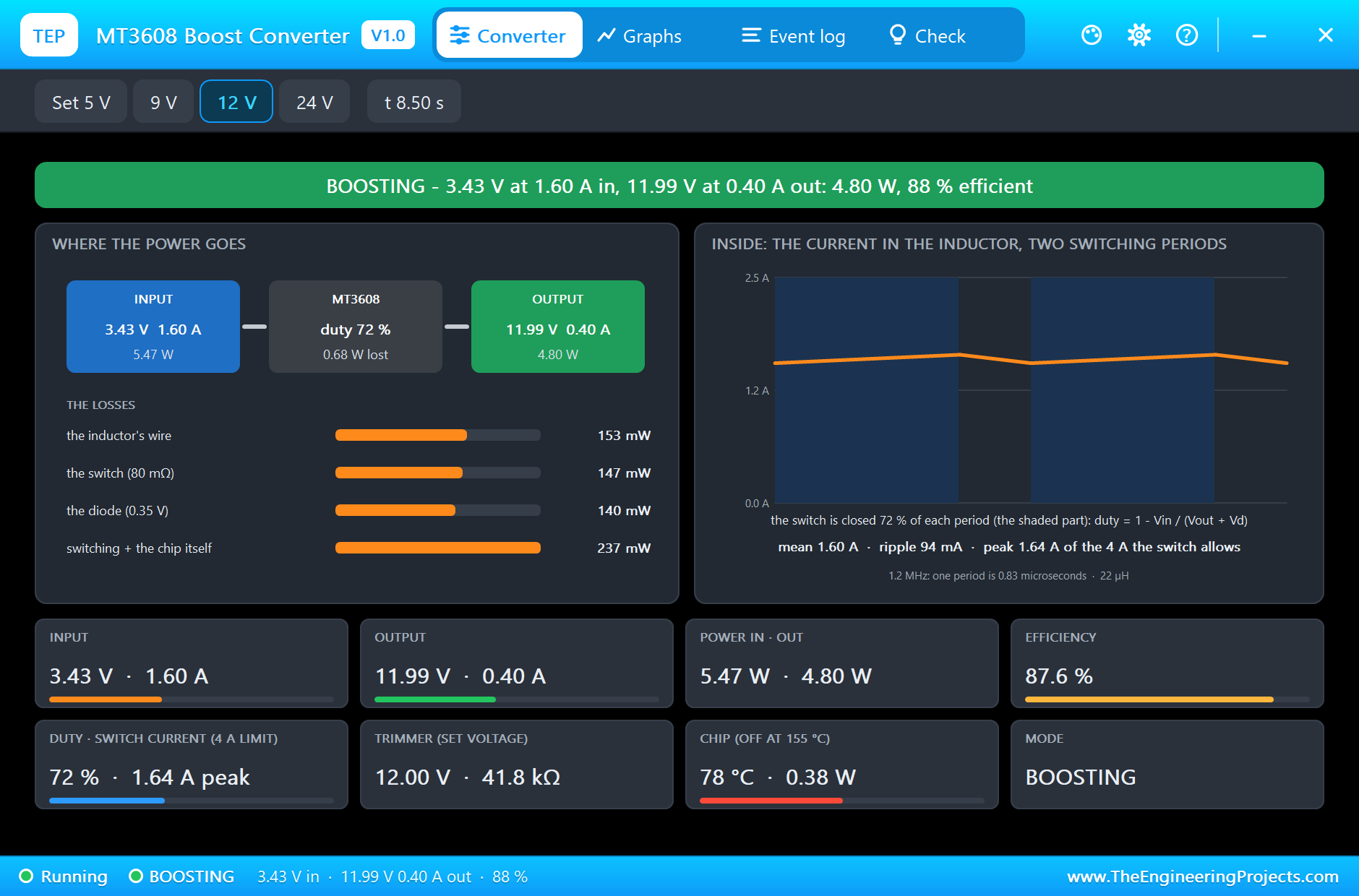
At 8.5 seconds the cell is at 3.43 V, and the module pulls 1.60 A to keep its 12 V: 5.47 W in for the same 4.80 W out, 87.6 percent. The chip is at 78 degrees. In the monitor the Arduino has begun to print LOW BATTERY, because the cell is under 3.5 V.
The Last Minutes of the Cell
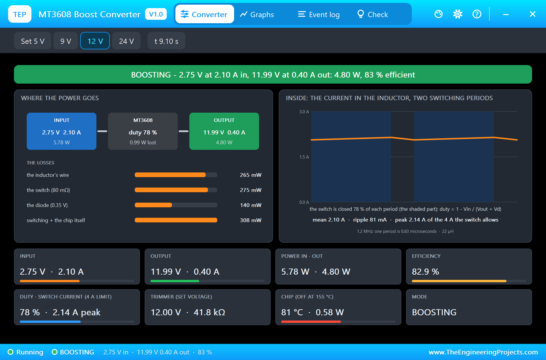
Now it goes fast. At 9.1 seconds the cell is nearly empty, 2.75 V, and the module takes 2.10 A from it, half as much again as at the start. The switch is closed 78 percent of each period, the losses have grown to 0.99 W, the efficiency is down to 82.9 percent and the chip is at 81 degrees. The output is still 11.99 V at 0.40 A: the load notices nothing.
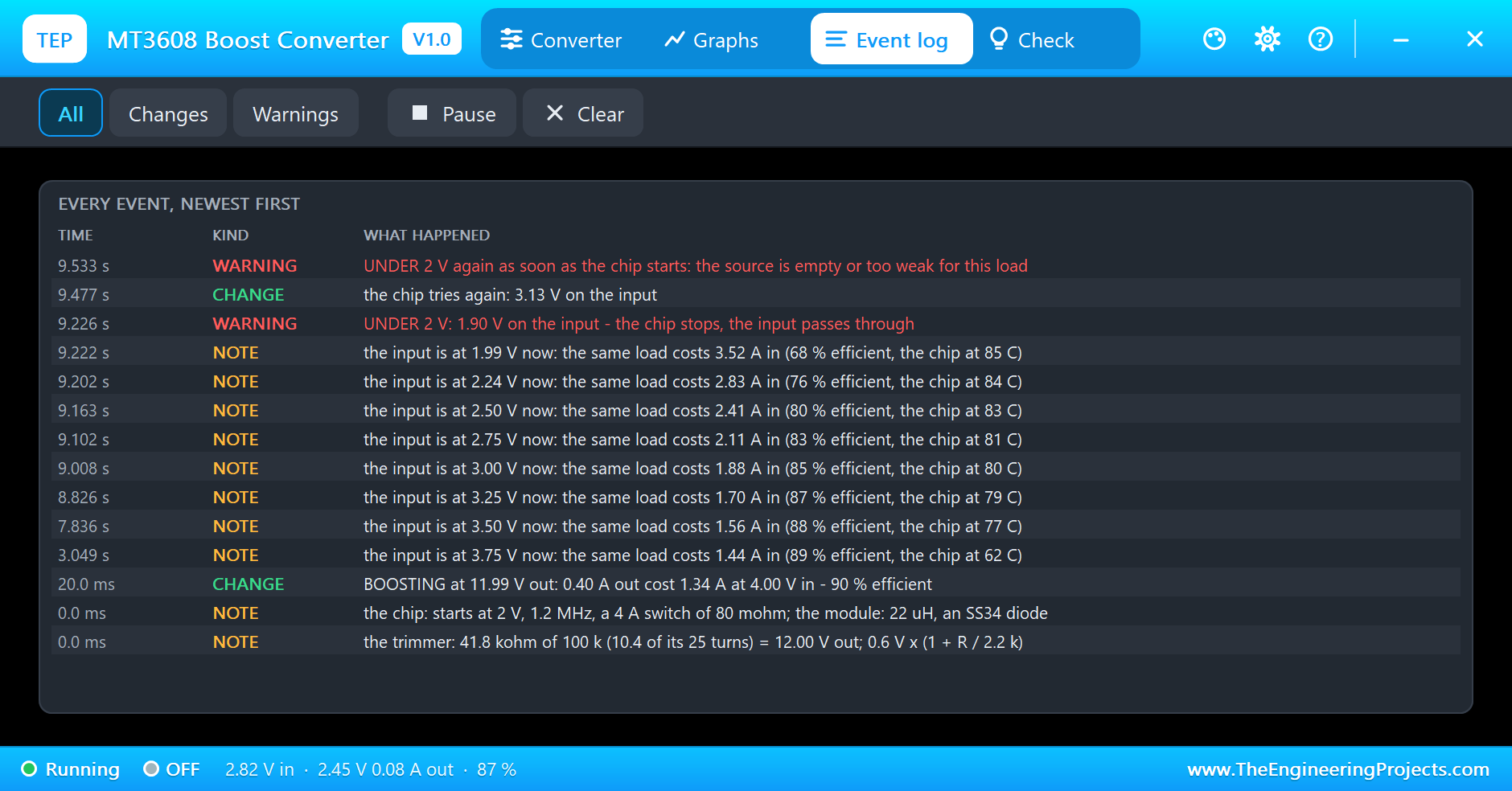
The Event log keeps the whole story, a line for every quarter of a volt: the same load cost 1.44 A at 3.75 V, 1.56 A at 3.50 V, 1.70 A at 3.25 V, 1.88 A at 3.00 V, 2.41 A at 2.50 V and 3.52 A at 1.99 V. This is the hard truth of every boost converter on a battery: the emptier the cell, the harder it is pulled, right to the end.
The Chip Stops
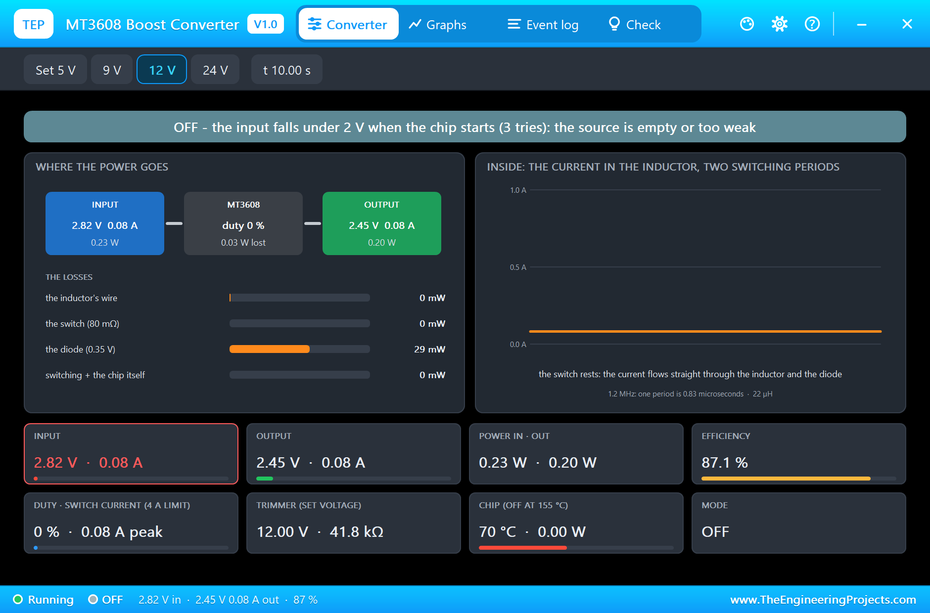
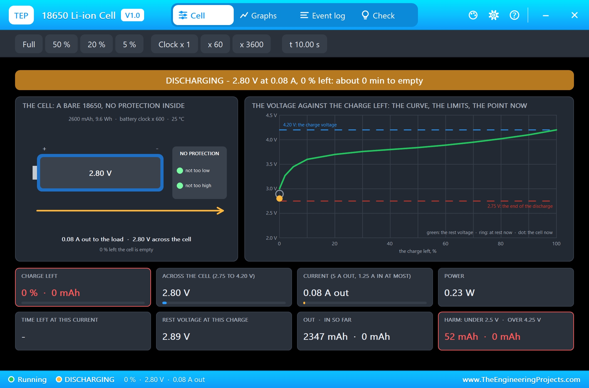
At 9.226 seconds the input falls under 2 V and the chip stops. Without the heavy current the cell recovers to 3.13 V, so a quarter of a second later the chip tries again, and is under 2 V again at once. The pop-up says it plainly: OFF, the input falls under 2 V when the chip starts, the source is empty or too weak. Only 2.45 V at 0.08 A still reach the load, straight through the inductor and the diode.
The cell's pop-up shows the damage: 0 percent left, 2347 mAh given, and 52 mAh of them were taken under 2.5 V, where a Li-ion cell comes to harm. The module works down to 2 V and does not care about the cell. That is why the sketch warns at 3.5 V: a real design must switch the load off there, or use a cell with a protection board.
Too Much Load: the Current Limit
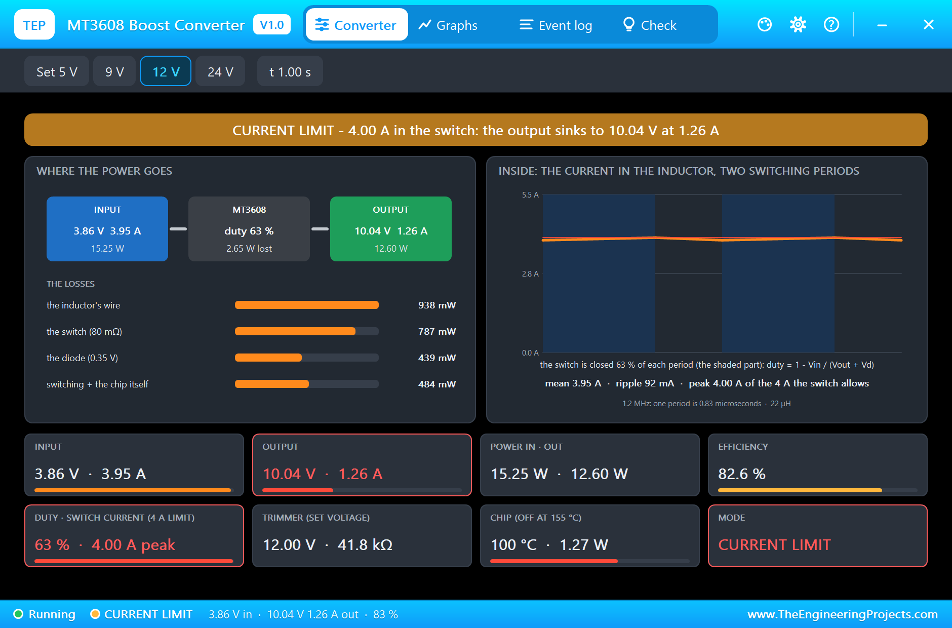
For a second simulation run we changed the load to 8 ohm. At 12 V that would be 1.5 A and 18 W, more than 4 A from the cell. The chip does not allow it: the banner turns amber, CURRENT LIMIT. The switch is at its 4.00 A peak, the cell gives 3.95 A at 3.86 V, and the output sinks to 10.04 V at 1.26 A. The efficiency is 82.6 percent, and the chip heats up fast: 100 degrees after one second, with 1.27 W lost in it.
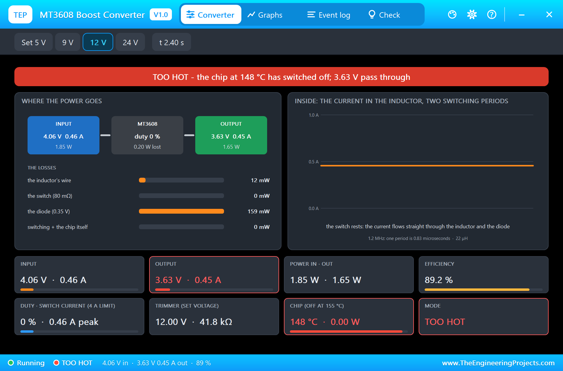
It cannot go on like that. At 2.294 seconds the chip reaches 155 degrees and switches itself off: TOO HOT. Only 3.63 V at 0.45 A pass through to the load while it cools. At 2.628 seconds it is down to 135 degrees and starts again, into the same limit. A real module does the same, and that is how most of them die.
The Trimmer Below the Input
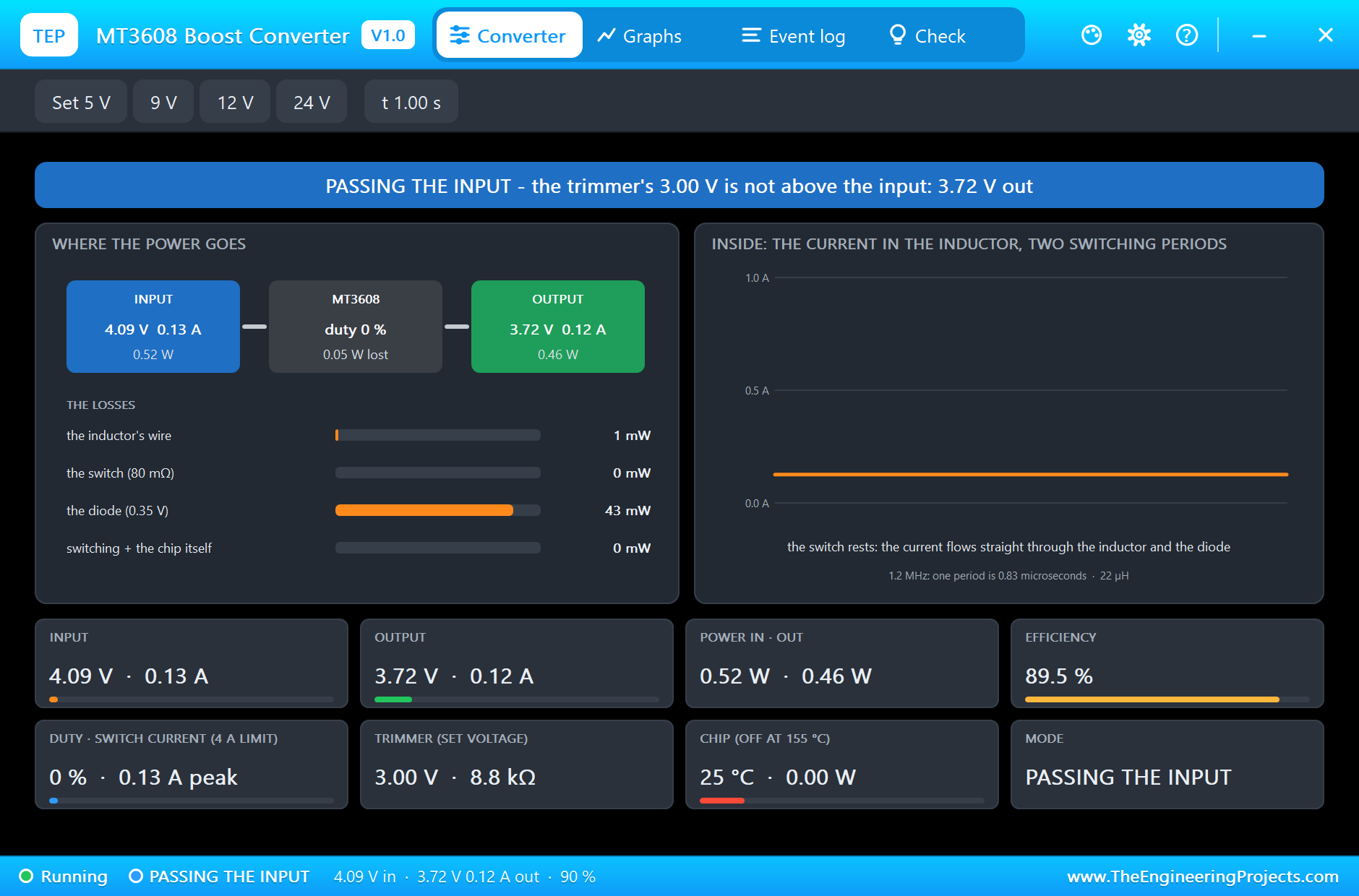
For a third run we set VOUT to 3 V, less than the cell has. The banner turns blue: PASSING THE INPUT. The switch rests, and 3.72 V at 0.12 A reach the load from the 4.09 V of the cell, through the inductor and the diode. A boost converter can only raise a voltage; it can never give less than its input, and it cannot switch its output off.
The Graphs, the Event Log and the Check Page
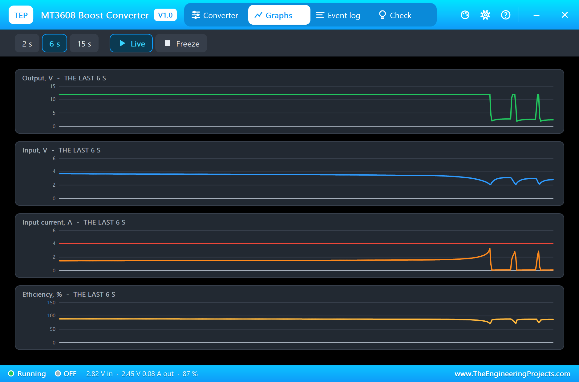
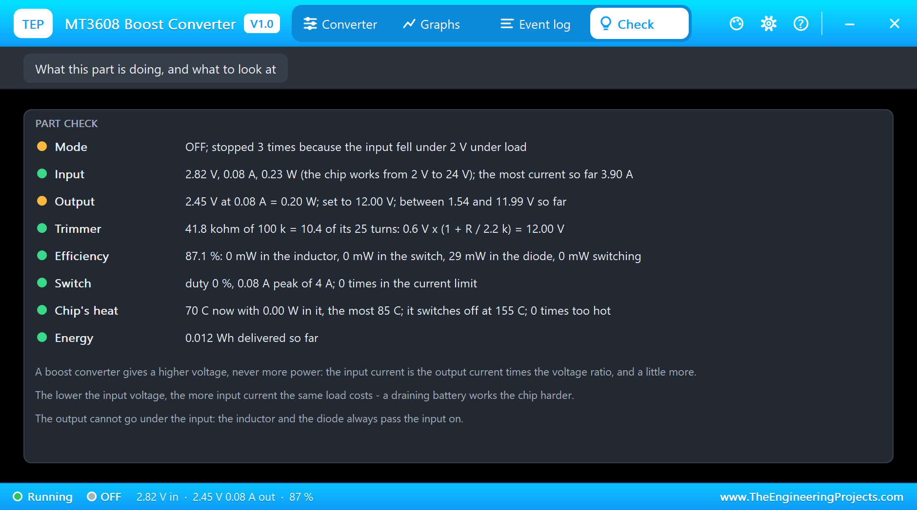
Back to the first run. The Graphs page plots the output voltage, the input voltage, the input current and the efficiency over the last 2, 6 or 15 simulated seconds. The output stays a straight line at 12 V while the input sinks and the input current climbs, steeply at the end; the spikes at the right are the tries of the chip on the empty cell. The Check page sums up the run: the output between 1.54 and 11.99 V, the most input current 3.90 A, and the chip never hotter than 85 degrees.
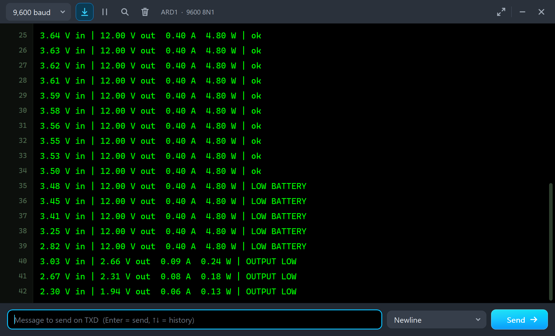
The monitor shows what the Arduino saw. Line after line the input voltage falls while the output stays at 12.00 V, 0.40 A and 4.80 W. From 3.48 V on the verdict is LOW BATTERY, five lines down to 2.82 V. Then the output is gone: 2.66 V, OUTPUT LOW.
Try It Yourself
- Click the Set 5 V or 9 V chip while the simulation runs: the output follows, and the input current falls with it.
- Change R1 to 60 ohm: half the load, less input current, and the cell lasts about twice as long.
- Set the SOC of the cell to 30: LOW BATTERY comes early.
- Set VOUT to 5 and R1 to 10 ohm: a 5 V supply of half an amp from one cell.
- Set TEMP to 50 and repeat the run with the 8 ohm load: the chip is too hot sooner.
Ideas to Extend the Demo
- Switch the load off with a MOSFET when the sketch says LOW BATTERY: the protection the module lacks.
- Charge the cell with our TP4056 charger module and boost it to 5 V: a power bank.
- Feed the module from a small solar panel instead of the cell.
- Measure the input current with a current sensor and let the Arduino work out the efficiency.
Your Own Sketches
The demo sketch is in the zip file, and you can change it in the Arduino IDE. New to Arduino? Start with our Arduino Tutorial for Beginners. Export the compiled binary, and set the UNO's PROGRAM property to the new file. Our guide on How to get the HEX file from Arduino shows you where the file ends up.
Things to Know Before Using a Real MT3608 Module
- Set the voltage first: the trimmer of a new module is often at its far end. Turn it many turns until the output moves, and set the voltage before you connect the load.
- Mind the input current: it is the output current times the voltage ratio, and more. Size the source and the wires for it, and remember that it grows as a battery runs down.
- Keep it cool: the chip limits at 4 A, but the little board gets hot long before. For steady work keep the input under about 2 A.
- The output is never off: the input always passes through the inductor and the diode. To switch the load off you need a switch.
- It does not protect the battery: the module works down to 2 V. Use a protected cell or watch the voltage.
- Up only: for 3.3 V from a Li-ion cell you need a step-down converter, not this module.
Troubleshooting
- The output is the input minus a little: the trimmer is set below the input (PASSING THE INPUT), the input is under 2 V (OFF), or the chip is too hot.
- The output sinks under load: the switch is in its current limit. Raise the input voltage or lighten the load.
- OFF, the input falls under 2 V when the chip starts: the source is empty or too weak for the input current. Charge the cell or lighten the load.
- TOO HOT: too much is lost in the chip. Lighten the load.
- The Arduino reads a wrong output voltage: the factor of the divider in the sketch does not match the two resistors.
- The part is not simulated:
TEPMT3608.DLLis missing from MODELS and from the project folder.
Limitations of the Simulation
- The figures of the chip (2 to 24 V in, up to 28 V out, 1.2 MHz, the 80 milliohm switch with its 4 A limit, the 0.6 V reference) are from its data sheet; the 22 uH inductor, the SS34 diode and the 100 k trimmer over 2.2 k are those of the usual module.
- It is a mean-value model: nothing switches at 1.2 MHz in the simulation and there is no ripple on the output. The picture of the inductor's current is calculated.
- Our own figures: the resistance of the inductor and the diode, the switching loss, 150 degrees per watt, the 155 and 135 degree thresholds, the 20 milliohm output, and the quarter of a second before the chip tries again after an undervoltage stop (a real chip tries again faster).
- Not modelled: pulse skipping at light load, the enable pin (tied to the input on the module), the surge into the output capacitor at the start.
- The energy on the Check page counts in simulated seconds, not in the cell's faster clock.
- The module is drawn at its true size. The lamp and the line with volts and amps on the board are ours; the real module has neither.
- Arduino is a name of Arduino; this library is not made or endorsed by Arduino, Labcenter or the makers of the chip and the module.
- Tested in Proteus 8.5 in November 2026 (the demo as shipped). Proteus 7 is not supported.
So, that was all about the MT3608 DC-DC Boost Converter Module Library for Proteus Simulation. I hope it helps you design and test your battery supply before the real module is on the bench, and shows why a boost converter empties a tired cell so quickly. If you have any questions, ask in the comments and I will help you out. Till the next tutorial, take care and have fun!

Comments
0