


PZEM-017 DC Energy Meter Library for Proteus Simulation


Hello friends, I hope you all are doing great. Today, I am going to share the new PZEM-017 DC Energy Meter Library for Proteus Simulation, the next library of our renewable energy series. If you have searched for a Proteus simulation of the PZEM-017, the small DC energy meter that solar and battery projects read over RS485, this library brings it into Proteus with its real Modbus registers, so that the same Arduino code runs on the simulation and on the real module.
PZEM-017 DC Energy Meter Library for Proteus Simulation
Latest version: V1.0 (November 2026, this tutorial)
Helping Tools
- Serial Monitor Advance: a serial terminal window for the UART of your board
- Serial Monitor Expert: the serial monitor with extra debugging tools
- LCD Library for Proteus V3.0: 16x2, 20x4 and I2C LCDs to show your readings
The meter is drawn compact, and at run time its three lamps work on your sheet, while its label plate shows the volts, the amps, the watts and the watt-hours it has measured. The simulation model measures the supply and the current through an external shunt, counts the energy, watches two voltage alarms, and answers Modbus-RTU requests byte for byte like the real module. The demo is a battery energy monitor: our lead-acid battery feeds a load, and an Arduino reads the meter through our MAX485 module.
NOTICE: Our team has put a lot of effort into these small parts: the bodies, the animation and the pop-ups are all our own design, and you get them free. Your feedback is the fuel that keeps us going, so please tell us what you think in the comments below or in the Motor Driver board of our forum. And if our free libraries help you, you can buy us a coffee. So, let's get started with the PZEM-017 DC Energy Meter Library for Proteus Simulation:
What is the PZEM-017?
The PZEM-017 is a DC energy meter in a small plastic case. It has no display. It measures the voltage of a DC supply and the current that flows through an external shunt, multiplies the two to get the power, and adds the power up over time to get the energy in watt-hours. A controller reads these four values over an RS485 line. That makes it a favourite for solar systems, battery banks, electric bikes and DC chargers, where the readings have to travel to an Arduino, an ESP32 or a PLC.
A shunt is a very small, very exact resistor. The whole current flows through it and leaves a few millivolts across it: a 50 A shunt gives 75 mV at 50 A, which is 1.5 milliohm. The meter measures those millivolts and works out the amps. With shunts of 50, 100, 200 and 300 A the same meter covers currents up to 300 A; a register tells it which shunt is fitted.
| PZEM-017 (the maker's specification) | |
|---|---|
| Voltage | 0.05 to 300 V DC, in steps of 0.01 V |
| Current | 0.02 to 300 A with a 50, 100, 200 or 300 A shunt, in steps of 0.01 A |
| Power | up to 90 kW, in steps of 0.1 W |
| Energy | 0 to 9999 kWh, in steps of 1 Wh |
| Accuracy | 1 % |
| Alarms | high voltage (300 V at the start) and low voltage (7 V at the start) |
| Supply | from the measured voltage above 7 V; below that, 5 V on its USB port |
| Interface | RS485, Modbus-RTU, 9600 baud, 8 data bits, 2 stop bits, no parity |
| Case | 90 x 60.5 x 23 mm |
Modbus-RTU: How the Meter is Read
RS485 is a pair of wires, A and B, that many devices can share. Modbus-RTU is the language spoken on it. One device, the master, asks; the others, the slaves, answer only when they are asked, each under its own address. A request is a short frame of bytes: the slave's address, a function code, the register to start at, the number of registers, and two bytes of CRC, a checksum that lets the receiver throw away a damaged frame.
The PZEM-017 keeps its measurements in eight measurement registers, read with function 0x04, and its settings in four parameter registers, read with 0x03 and written with 0x06:
| Register | Read with 0x04 | One step |
|---|---|---|
| 0x0000 | Voltage | 0.01 V |
| 0x0001 | Current | 0.01 A |
| 0x0002, 0x0003 | Power, the low word first | 0.1 W |
| 0x0004, 0x0005 | Energy, the low word first | 1 Wh |
| 0x0006 | High voltage alarm | 0xFFFF = alarm |
| 0x0007 | Low voltage alarm | 0xFFFF = alarm |
| Register | Read with 0x03, written with 0x06 | Values |
|---|---|---|
| 0x0000 | High voltage alarm threshold | 5 to 350 V, in steps of 0.01 V |
| 0x0001 | Low voltage alarm threshold | 1 to 350 V, in steps of 0.01 V |
| 0x0002 | Modbus address | 1 to 247 |
| 0x0003 | Current range (the shunt) | 0 = 100 A, 1 = 50 A, 2 = 200 A, 3 = 300 A |
One more function, 0x42, sets the energy counter back to zero. To read everything at once the master sends eight bytes: 01 04 00 00 00 08 and the CRC. The meter answers with the eight registers, sixteen data bytes. A 16-bit register holds at most 65535, so the power and the energy each use two registers; the low half comes first, which is easy to get wrong.
Features of the PZEM-017 DC Energy Meter Library for Proteus Simulation
- A compact meter: the dark ribbed case with its two green terminal blocks, drawn a little smaller than an Arduino UNO (the real case is 90 x 60.5 mm).
- Real measurements: volts in steps of 0.01 V, amps from the millivolts of your shunt in steps of 0.01 A, watts in steps of 0.1 W, watt-hours counted up.
- Four shunts: 50, 100, 200 or 300 A at 75 mV, set by a property or by register 3.
- Two alarms: a high and a low voltage alarm with thresholds the master can write.
- The real Modbus-RTU: functions 0x03, 0x04, 0x06 and 0x42 with the real register map, the address, the general and the broadcast address, the CRC and the exceptions; 9600 baud with two stop bits.
- An RS485 pair: A and B work with our MAX485 module, and several meters with different addresses can share one line.
- Live on the sheet: PWR, TX and RX lamps, and the four values on the label plate.
- A pop-up: the circuit with the shunt, the last Modbus frames byte by byte with their meaning, eight live values, graphs, an event log and a check page.
- A complete package: about 1.6 MB with the library, our lead-acid battery, our Arduino UNO V4.0 and the demo, without the source code of the model.
The PZEM-017 in Proteus
The device is PZEM017TEP in TEPPZEM017.LIB, under Electromechanical > Energy Meters, with the prefix EM and the model TEPPZEM017.DLL. Search PZEM in Pick Devices. It has eight pins. On the left are V+ and V-, the supply to be measured, and SH- and SH+, the two sense wires of the shunt. On the right is the RS485 side: 5V, B, A and GND. The properties are ADDRESS (the Modbus address), RANGE (the shunt: 50, 100, 200 or 300), USB (YES when the measured voltage is under 7 V) and SPEED (the clock of the energy counter, to be set like the SPEED of our battery libraries).
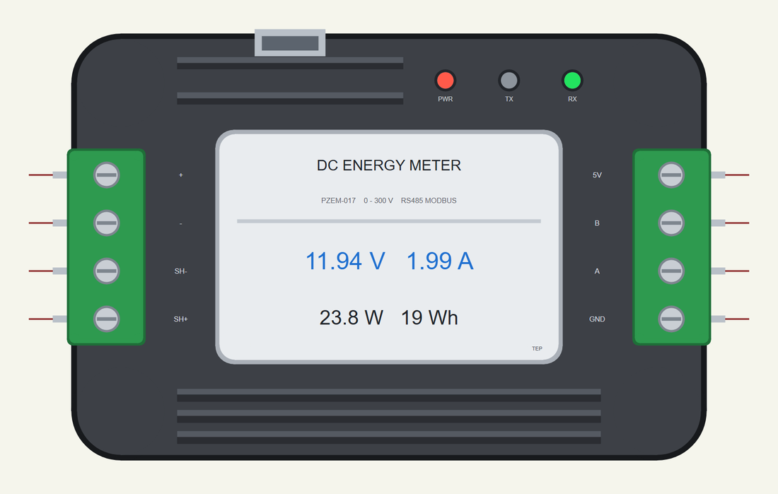
The shunt belongs in the negative lead, between the supply's minus and the load's minus. V- and SH- go to the shunt's end on the supply's side, and SH+ goes to its end on the load's side. In Proteus an ordinary resistor of the shunt's value does the job: 0.0015 ohm for a 50 A shunt.
Download PZEM-017 DC Energy Meter Library for Proteus Simulation
Click the button below to download PZEM-017-DC-Energy-Meter-Library-for-Proteus-v1.0.zip (about 1.6 MB, without the source code of the models):
PZEM-017 DC Energy Meter Library for Proteus V1.0- README.txt: installation, the demo, the wiring, troubleshooting and the limits of the simulation.
- Proteus Library Files:
TEPPZEM017.LIB,TEPLEADACID.LIBandArduinoV4TEP.LIB. - Proteus Model Files:
TEPPZEM017.DLL,TEPLEADACID.DLLandTEPARDUINO.DLL. - Arduino Code: the demo sketch.
- Proteus Simulation: the demo project, its HEX file and copies of the DLLs.
No Proteus yet? Read How to Download and Install Proteus 7 and 8. New to libraries? Follow How to Install a New Library in Proteus.
How to Install PZEM-017 DC Energy Meter Library for Proteus Simulation
- Close Proteus and extract the whole zip file, for example to your Desktop.
- Copy the files from Proteus Library Files into the LIBRARY folder of Proteus.
- Copy the files from Proteus Model Files into the MODELS folder.
- Delete
TEPPZEM017.IDXfrom the LIBRARY folder if it is there. - The demo also uses our MAX485 RS-485 Module Library for Proteus: install it from its own package (it is not in this zip).
- Start Proteus, press P and search for PZEM.
Proteus Simulation of a Battery Energy Monitor with Arduino
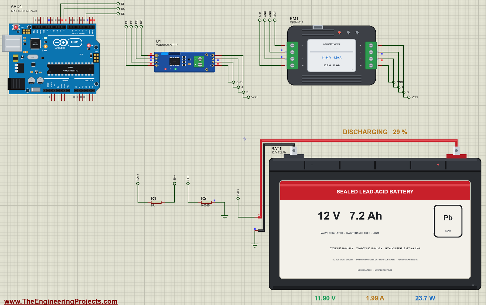
The demo is a battery energy monitor, the heart of every small solar or wind system. The battery, BAT1, is the 12 V 7.2 Ah battery of our 12V Lead-Acid Battery Library for Proteus Simulation, starting at 60 percent. It feeds a load, R1, 6 ohm, and the current comes back through R2, 0.0015 ohm, which stands for a 50 A shunt in the negative lead. The meter, EM1, has V+ on the battery's plus, V- and SH- on its minus, and SH+ on the load's side of the shunt; its RANGE is 50. On the other side, its A and B go to U1, the pop-up version of our MAX485 RS-485 Module Library for Proteus, and that module's RO, DI and DE with RE go to pins 8, 9 and 2 of our Arduino UNO Library for Proteus V4.0. The Arduino's built-in monitor is the same window as our TEP Serial Monitor Advance for Proteus. The SPEED of the battery and of the meter is 3600, so one simulated second is an hour. Open PZEM-017-Energy-Meter-RS485-Battery-ArduinoUnoV4.pdsprj.
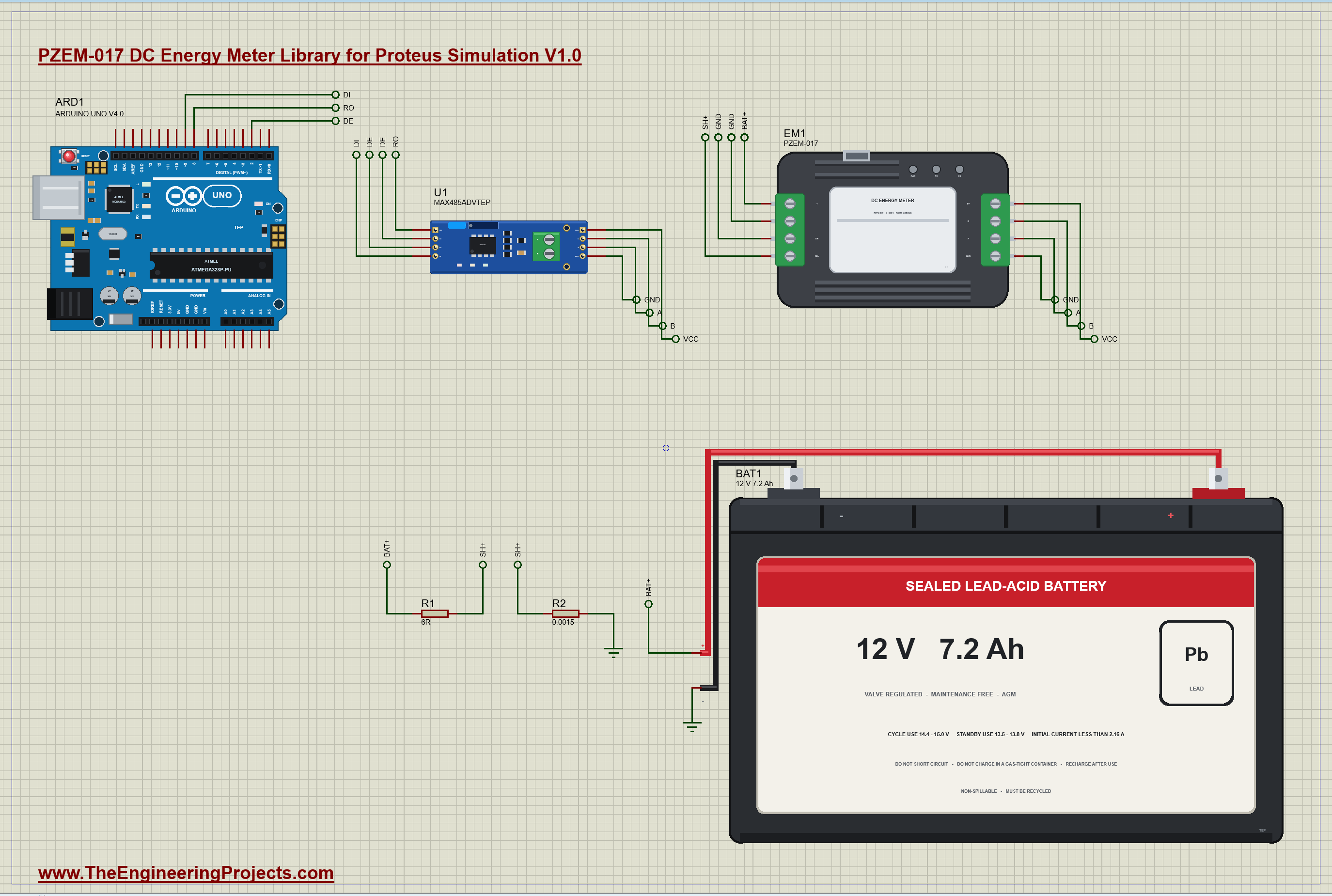
In the simulation the measuring side and the RS485 side share one ground. In the real module they are separated by optocouplers, so the Arduino stays safe even when the meter sits on a 300 V supply.
The Sketch
Most Arduino examples for this meter hide the protocol in a library. Our sketch is a small Modbus master written out by hand, so that every byte can be seen. A request ends with its CRC, and Modbus wants the low byte first:
frame[n] = c & 0xFF; frame[n + 1] = c >> 8; // the CRC's low byte goes firstThe MAX485 module can either send or listen. The sketch raises DE and RE, writes the frame, waits until the last bit has left, and lets the pair go so that the meter can answer:
  digitalWrite(DE_RE, HIGH);
  rs485.write(frame, n + 2);
  rs485.flush();                               // wait until the last stop bit is out
  digitalWrite(DE_RE, LOW);
Twice a second it asks for all eight measurement registers. These six bytes, with the two CRC bytes behind them, are the whole request:
frame[0] = METER; frame[1] = 0x04; frame[2] = 0; frame[3] = 0; frame[4] = 0; frame[5] = 8; // eight registers from 0x0000In the answer the power and the energy each fill two registers, the low half first. The sketch puts the halves together the right way round:
const unsigned long power = (unsigned long)frame[9] << 24 | (unsigned long)frame[10] << 16 | (unsigned int)frame[7] << 8 | frame[8];At the start the sketch writes two parameter registers: register 3 tells the meter that a 50 A shunt is fitted, as a real module needs it (a new one expects 100 A), and register 1 sets the low voltage alarm to 11.80 V. The LED on pin 13 lights with that alarm. You can type reset to set the meter's energy counter back to zero or rate 1000 to report once a second. The sketch needs the AltSoftSerial library; install it with the Library Manager.
PZEM-017 Simulation Results
Open the project and press Run. The demo runs 1.6 simulated seconds, which are a little over an hour and a half for the battery; with the pop-ups open and the pictures being taken it took 84 seconds on our PC. Click the meter for its pop-up. Every number below comes from one simulation run, the demo exactly as it ships.
The First Frames
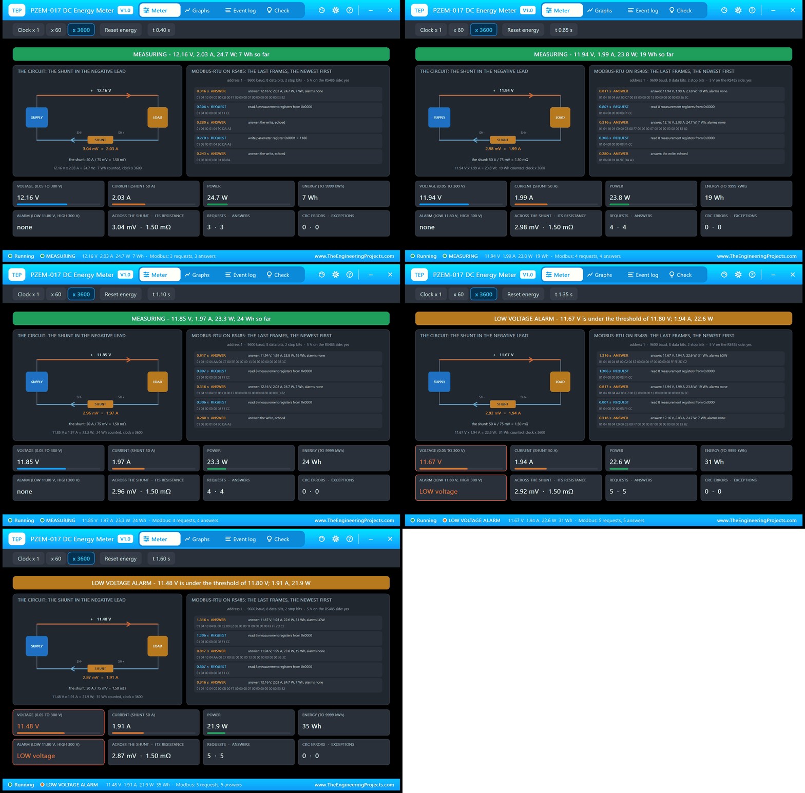
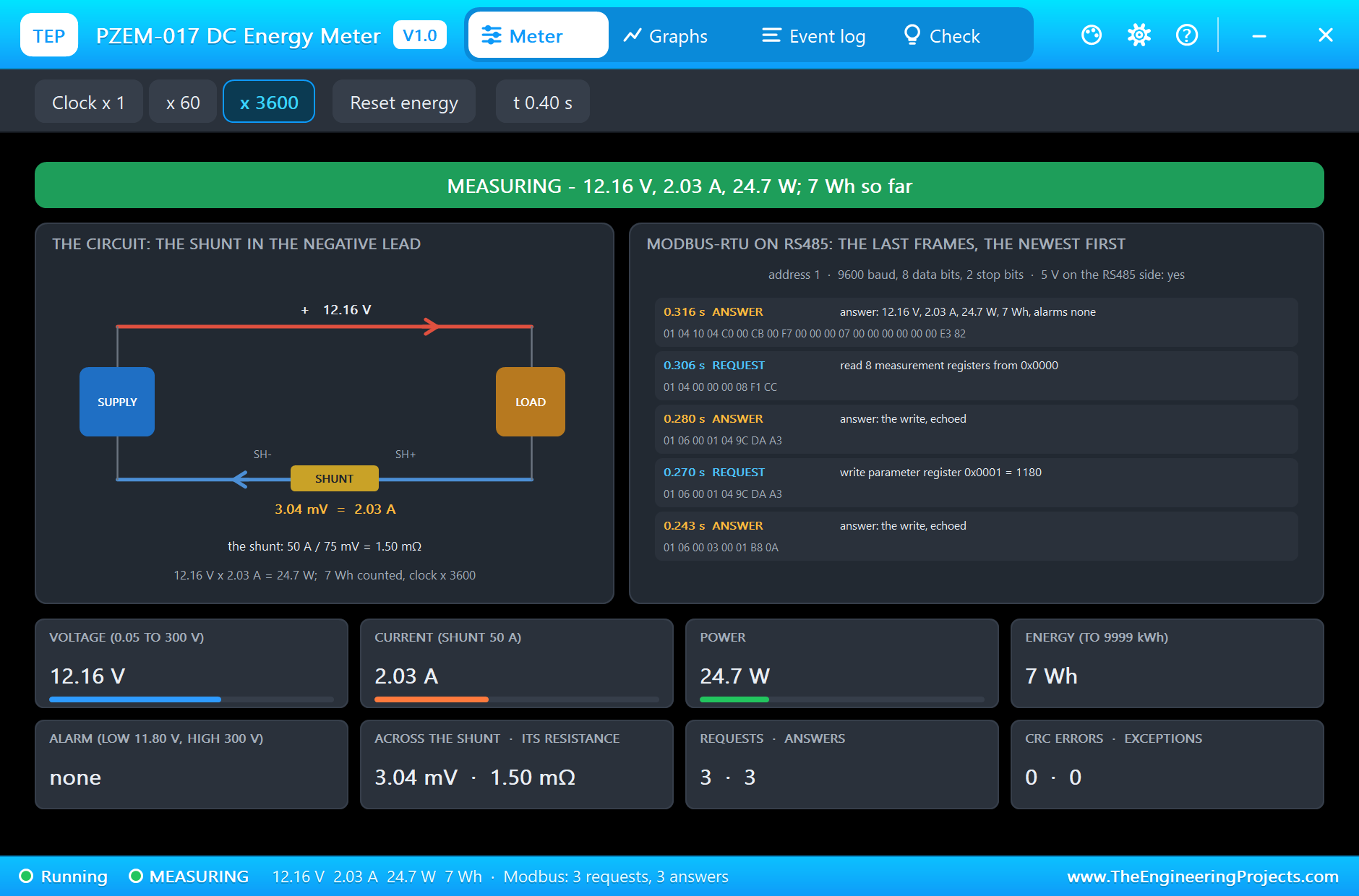
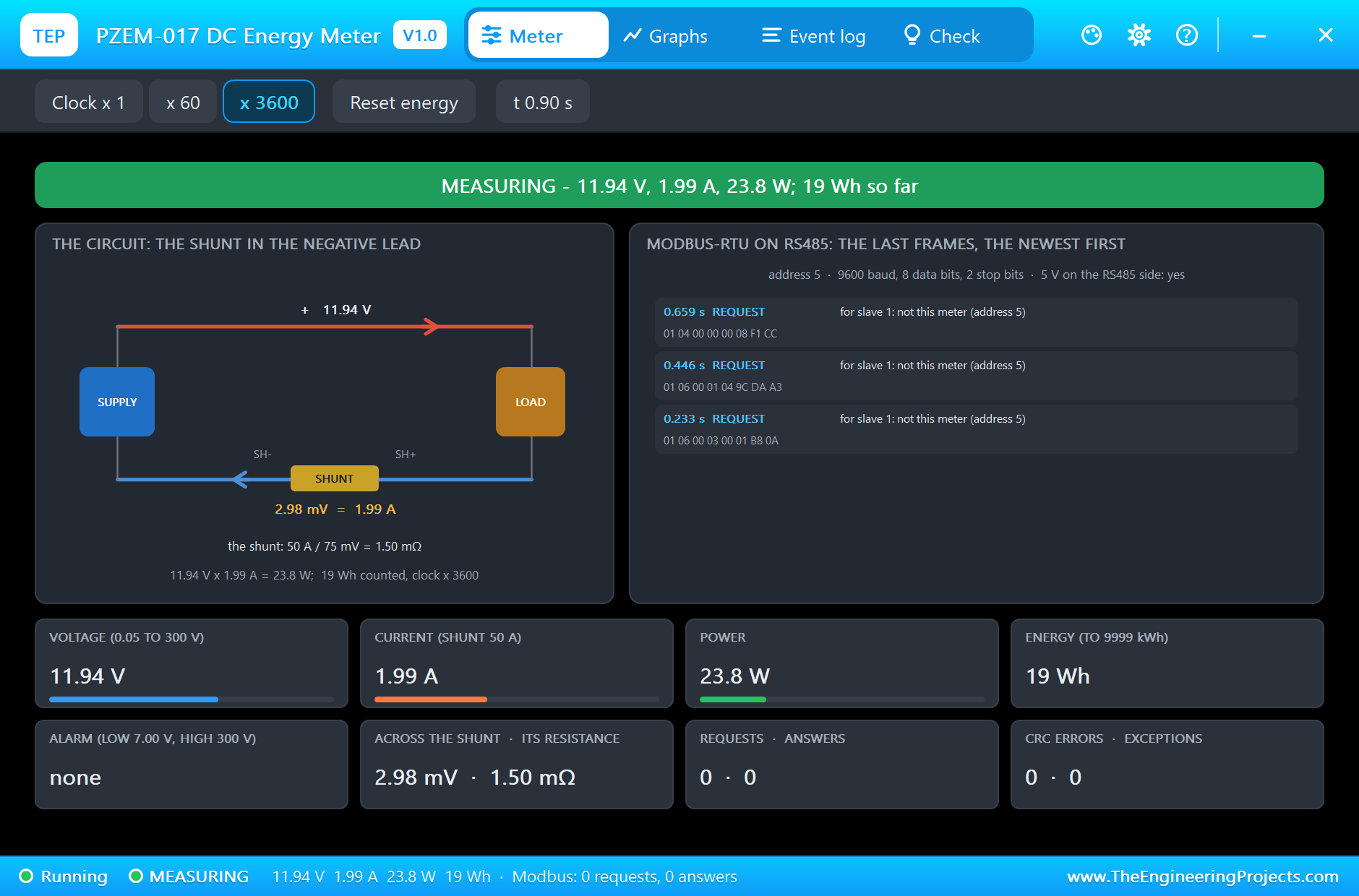
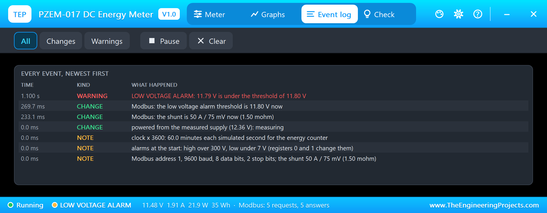
The Arduino starts with its two writes. The meter's Event log notes them: the shunt at 233.1 ms and the alarm threshold at 269.7 ms. Then the reading begins. The pop-up at 0.4 s shows the meter at work: 12.16 V, 2.03 A, 24.7 W and 7 Wh so far. On the left is the circuit with the shunt: 3.04 mV across its 1.5 milliohm are 2.03 A. On the right are the last frames on the RS485 pair, the newest first, each with its bytes and its meaning: the two writes, each echoed by the meter, and above them the first read with its answer.
Reading the Bytes
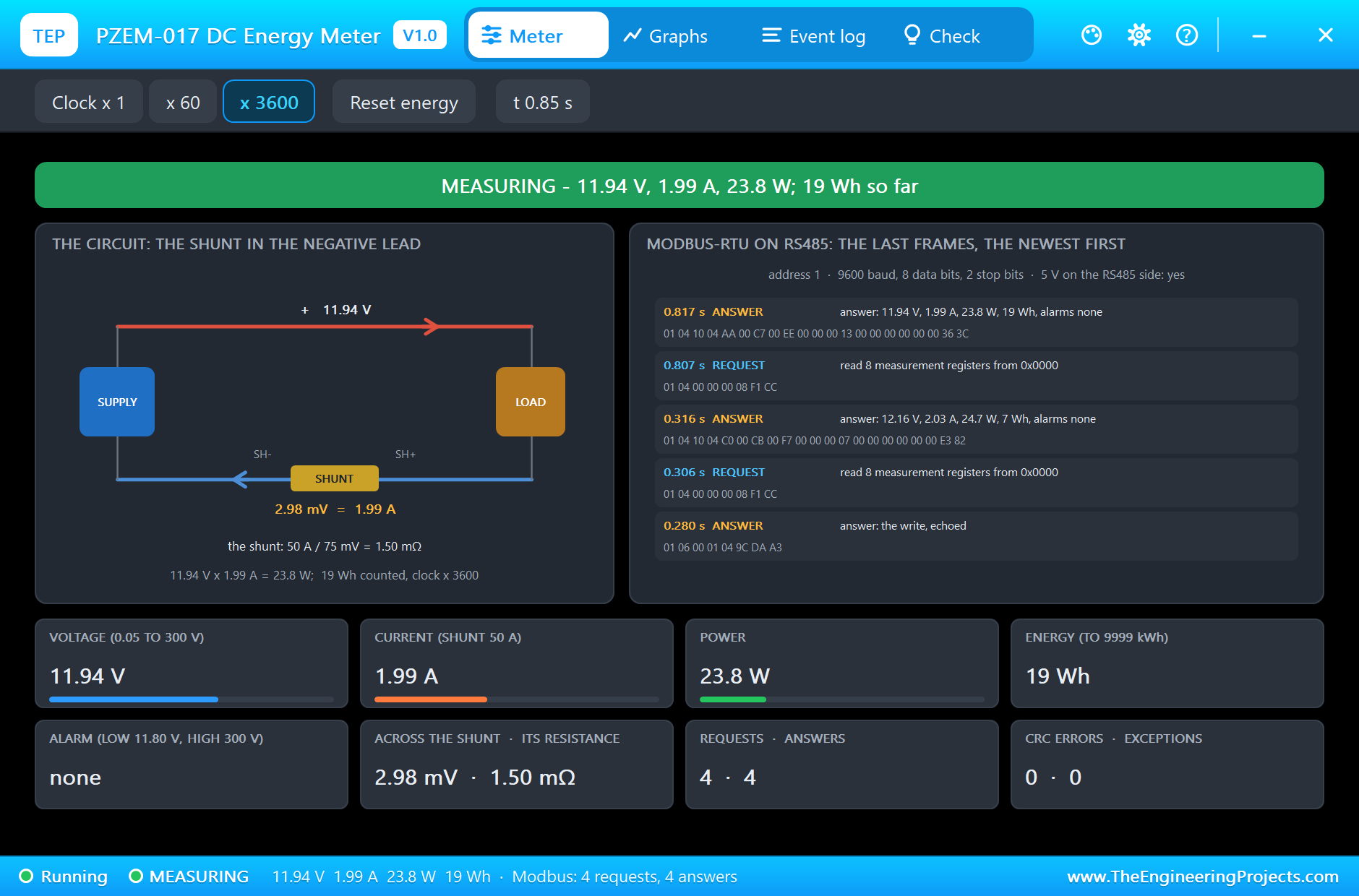
The pop-up at 0.85 s lets us read a whole exchange. The request is 01 04 00 00 00 08 F1 CC: slave 1, function 04, start at register 0000, eight registers, and the CRC. The answer is 01 04 10 04 AA 00 C7 00 EE 00 00 00 13 00 00 00 00 00 00 36 3C. After the address, the function and the byte count 10 (sixteen bytes) come the registers: 04 AA is 1194, so 11.94 V; 00 C7 is 199, so 1.99 A; the power's low half 00 EE is 238, so 23.8 W, with its empty high half 00 00 behind it; the energy's low half 00 13 is 19 Wh, again with 00 00 behind it. The two alarm registers are zero, and the last two bytes are the CRC.
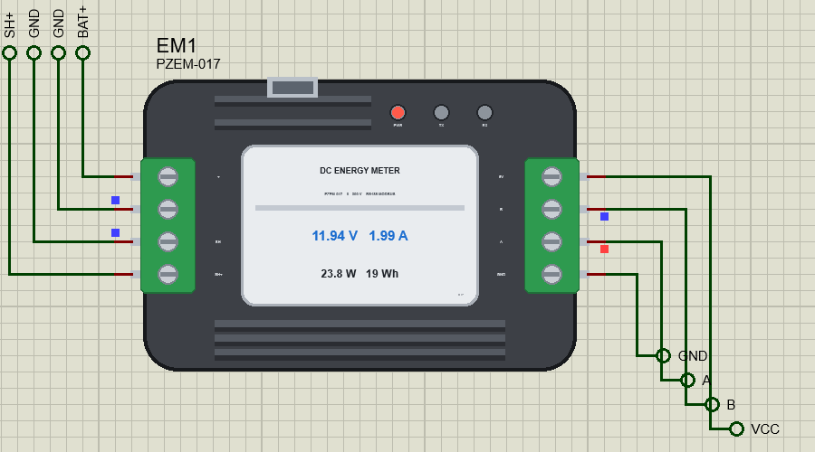
On the sheet the PWR lamp is red, the TX and RX lamps flash with every exchange, and the plate shows the four values.
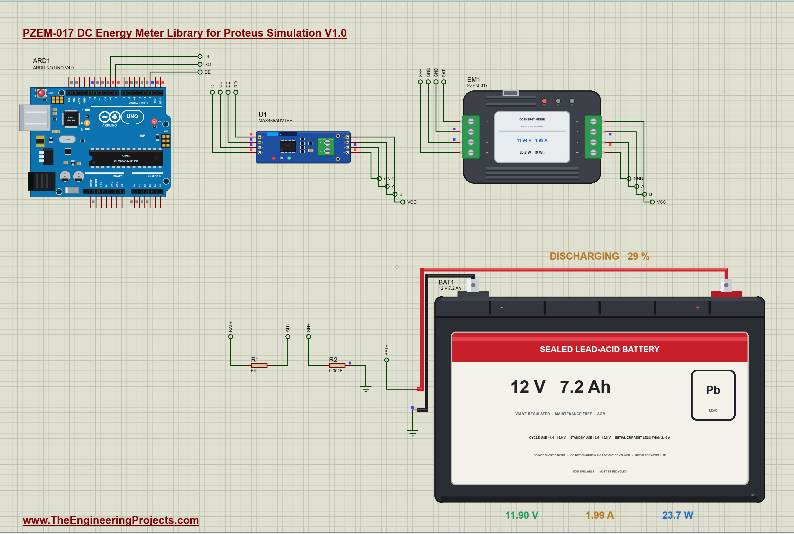
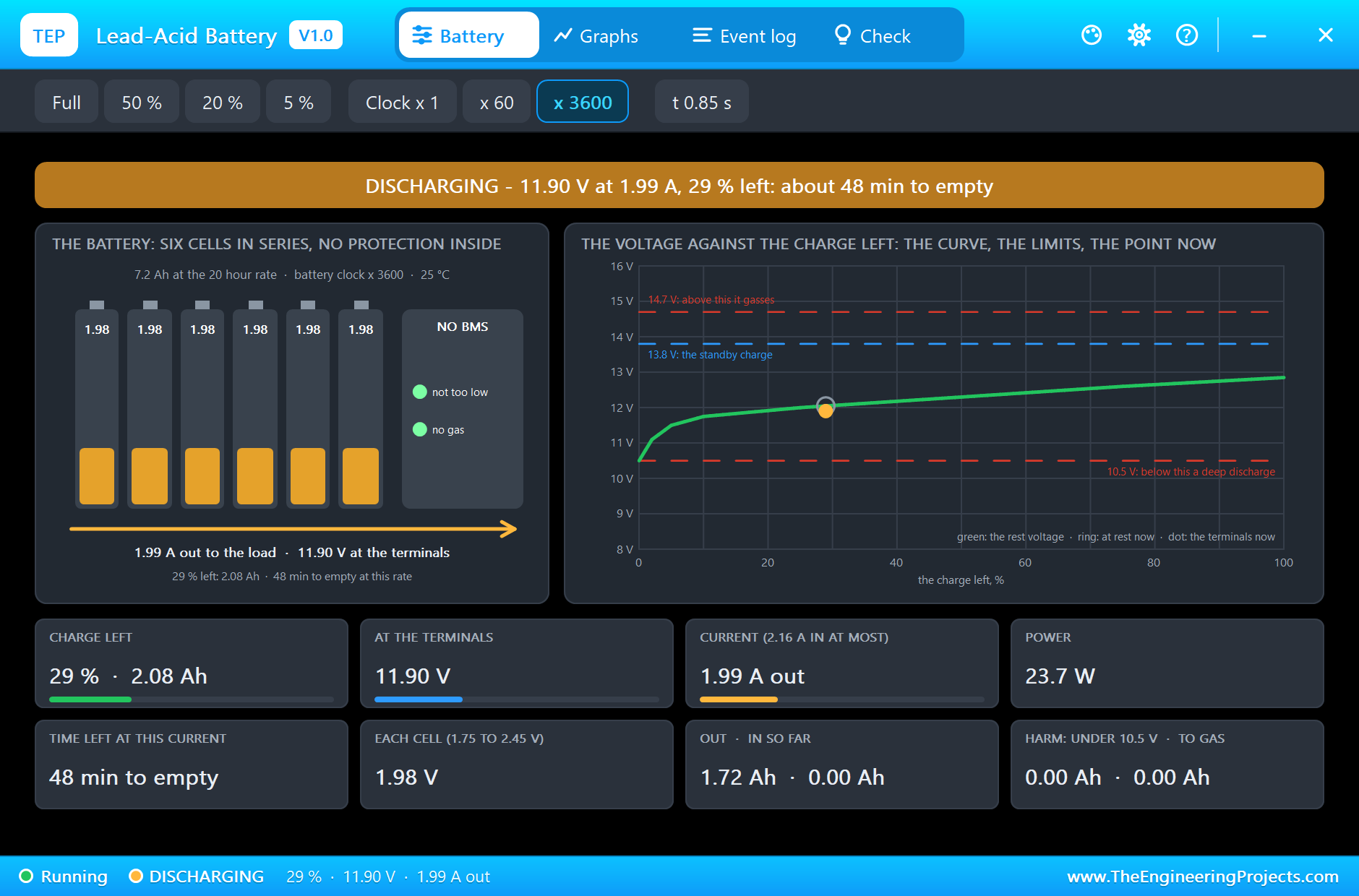
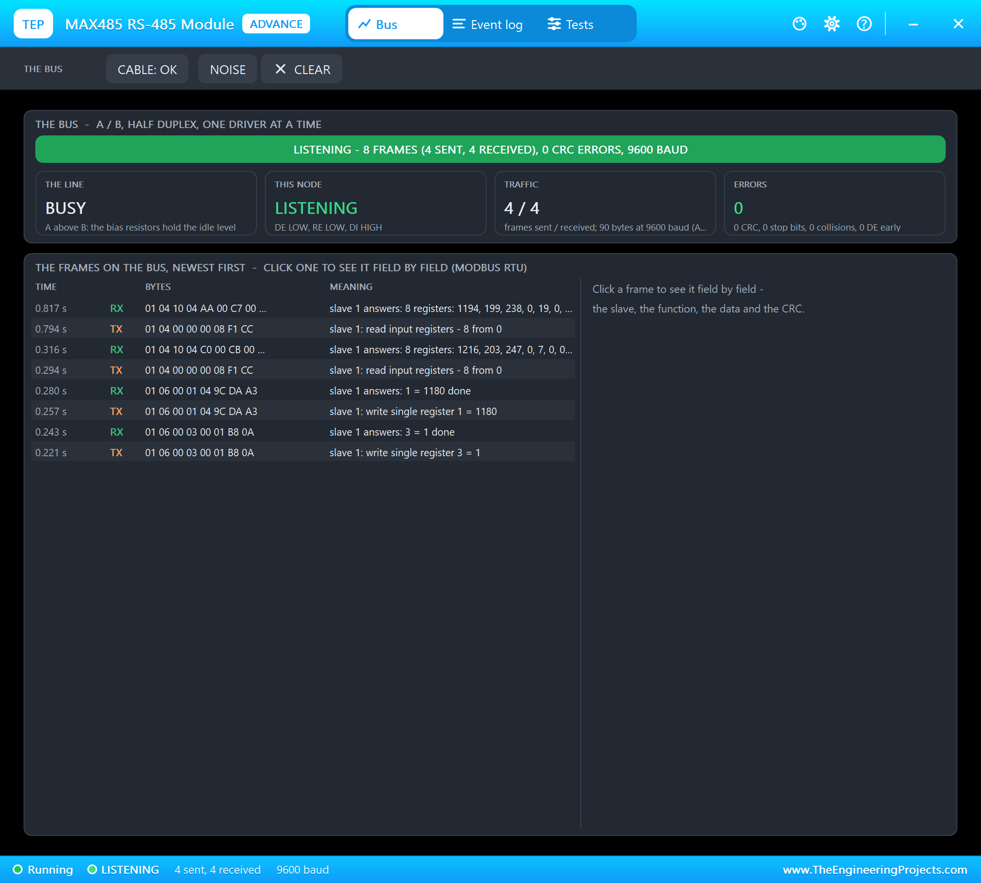
The other pop-ups agree. The battery gives 1.99 A at 11.90 V with 29 % of its charge left. That is a few hundredths of a volt under the meter's 11.94 V, and rightly so: the meter shows the mean of its last tenth of a second, and with the clock at 3600 the battery loses that much in the time between. The MAX485 module's own pop-up decodes the same frames from the bus side, as a second opinion: eight frames so far, four sent and four received, and no CRC error.
The Low Voltage Alarm
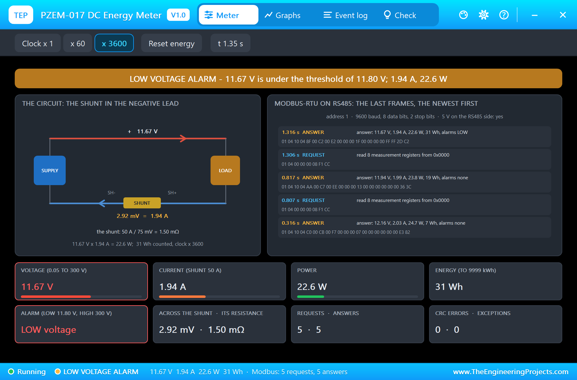
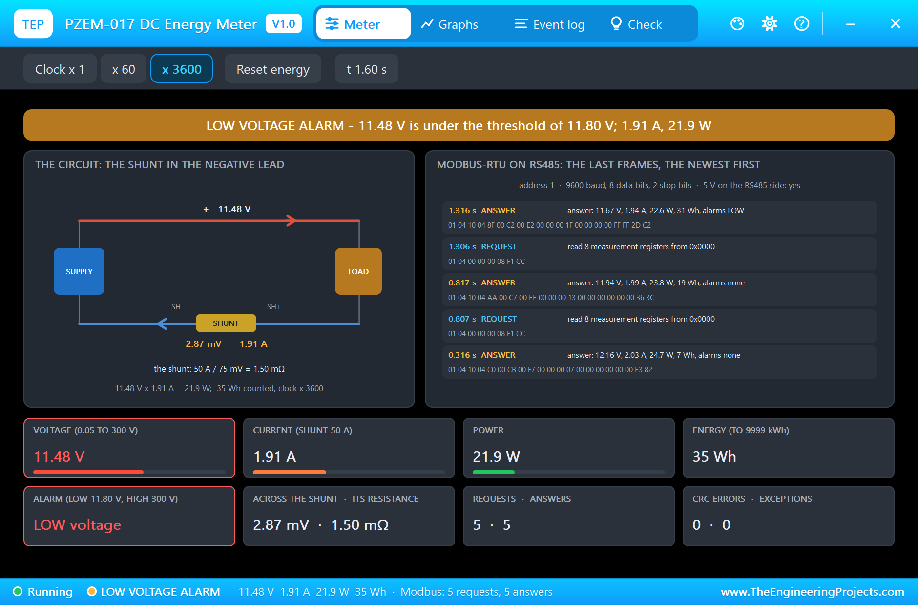
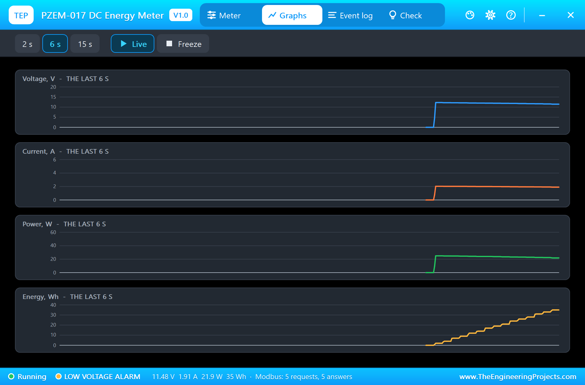
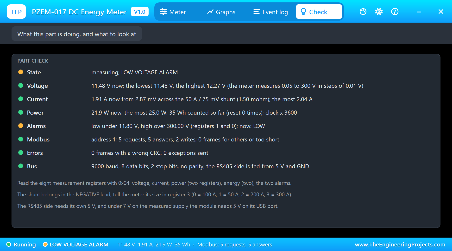
The battery runs down, and its voltage with it. At 1.100 s the meter measures 11.79 V, under the 11.80 V the sketch has set: the Event log writes LOW VOLTAGE ALARM, and from now on register 7 of every answer is FFFF. The pop-up at 1.35 s shows it: 11.67 V, 1.94 A, 22.6 W. At 1.6 s the battery is down to 11.48 V, and the energy counter stands at 35 Wh. The Arduino sees the alarm in the answer and lights its LED: the moment to switch the load off and save the battery.
A Wrong Address
For a second simulation run we set the meter's ADDRESS to 5 and left the sketch asking for slave 1. The meter hears every request, sees that it is for another slave, and stays silent, as Modbus demands. Its frame list says so, and the Arduino prints that there is no answer. The meter goes on measuring, but its low alarm stays at 7 V, because the write never reached it. This is the most common fault on a real RS485 line, next to swapped A and B wires.
The Graphs, the Event Log and the Check Page
Back to the first run. The Graphs page plots the voltage, the current, the power and the energy over the last 2, 6 or 15 simulated seconds. The Event log keeps the writes, the alarm and every warning. The Check page sums up the run: the voltage between 11.48 V and 12.27 V, the most current 2.04 A, the most power 25.0 W, 5 requests and 5 answers, no CRC errors.
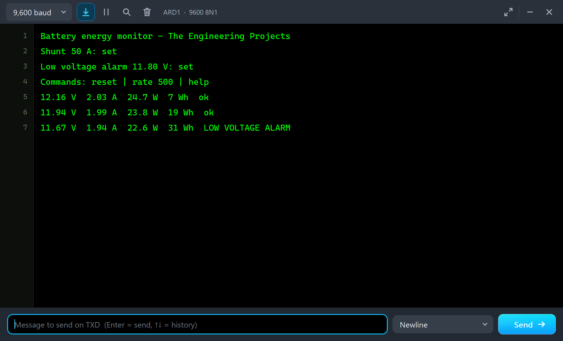
The monitor shows what the Arduino made of the answers: the two settings confirmed, then a line every half second, from 12.16 V and 2.03 A down to 11.67 V, with the energy climbing to 31 Wh and the words LOW VOLTAGE ALARM at the end.
Try It Yourself
- Type
resetin the monitor: the sketch sends function 0x42, and the meter's energy counter goes back to zero. - Change R1 to 3 ohm: about twice the current and the power, and the battery reaches the alarm much sooner.
- Set the meter's RANGE to 100 and remove the write of register 3 from the sketch: every current now reads twice the truth. The shunt setting matters.
- Put a second PZEM-017 with ADDRESS 2 on the same A and B and read both from one sketch: that is what RS485 is for.
- Set the battery's SOC to 100: the alarm comes much later.
Ideas to Extend the Demo
- Let the Arduino switch the load off with a relay or a MOSFET when the alarm register is set: a low voltage disconnect.
- Measure the output of our solar panel or wind turbine libraries instead of a battery, and log the energy of a day.
- Show the four values on an LCD, a small power meter for a camper van or a boat.
Your Own Sketches
The demo sketch is in the zip file, and you can change it in the Arduino IDE. New to Arduino? Start with our Arduino Tutorial for Beginners. Export the compiled binary, and set the UNO's PROGRAM property to the new file. Our guide on How to get the HEX file from Arduino shows you where the file ends up.
Things to Know Before Using a Real PZEM-017
- The shunt goes in the negative lead: between the supply's minus and the load's minus, with the sense wires on its two small screws.
- Set the shunt once: a new module expects a 100 A shunt. Write register 3 for any other, or every current is wrong.
- High voltage is deadly: the meter measures up to 300 V DC. Fuse the V+ wire and work without voltage.
- The RS485 side needs 5 V: it is fed from the adapter or the Arduino, not from the measured supply.
- Under 7 V use the USB port: and never feed that port from a PC while measuring; the maker warns that the PC can be damaged.
Troubleshooting
- No answer from the meter: A and B are swapped, DE and RE are not switched, the address is wrong, or the RS485 side has no 5 V. The pop-up's frame list shows what arrived.
- NO SUPPLY on the plate: under 7 V on V+ and V-. Set USB to YES for a low test voltage.
- The current reads 0: the shunt is not in the negative lead, or SH- and SH+ are not on its two ends.
- The current is wrong by a factor: register 3 does not match the shunt.
- The power or the energy looks wrong: each is two registers, the low word first.
- CRC errors in the pop-up: the master sends the CRC's high byte first. Modbus sends the low byte first.
- The part is not simulated:
TEPPZEM017.DLLis missing from MODELS and from the project folder.
Limitations of the Simulation
- The ranges, the steps, the alarms, the supply rule, the serial format, the function codes, both register tables and the CRC are from the maker's specification of the module; the wiring with the shunt in the negative lead is from its wiring picture.
- Our own figures: 10 mA for the module itself, ten measurements a second, the answer 10 ms after the request, and the three lamps on the case.
- The meter is drawn compact, at 0.7 of its real size.
- Not modelled: the 1 % accuracy band, the isolation between the two sides (they share the ground in the simulation), the storing of the parameters while the power is off, and the smaller sister module with a built-in 10 A shunt.
- Arduino is a name of Arduino; this library is not made or endorsed by Arduino, Labcenter or the maker of the PZEM modules.
- Tested in Proteus 8.5 in November 2026 (the demo as shipped). Proteus 7 is not supported.
So, that was all about the PZEM-017 DC Energy Meter Library for Proteus Simulation. I hope it helps you write and test your energy monitor before the real module arrives, and takes the mystery out of Modbus: a frame is only an address, a function, a few registers and a checksum. If you have any questions, ask in the comments and I will help you out. Till the next tutorial, take care and have fun!

Comments
0