


Grid-Tie Micro Inverter Library for Proteus Simulation


Hello friends, I hope you all are doing great. Today, I am going to share the new Grid-Tie Micro Inverter Library for Proteus Simulation, the last library of our renewable energy series. If you have searched for a Proteus simulation of a solar inverter that feeds into the mains, this library brings one into Proteus, together with the mains itself: connect a panel on one side and the grid on the other, and watch the inverter find the panel's best point, fall into step with the grid, and stop the moment the grid is gone.
Grid-Tie Micro Inverter Library for Proteus Simulation
Latest version: V1.0 (November 2026, this tutorial)
Helping Tools
- Serial Monitor Advance: a serial terminal window for the UART of your board
- Serial Monitor Expert: the serial monitor with extra debugging tools
- LCD Library for Proteus V3.0: 16x2, 20x4 and I2C LCDs to show your readings
The inverter is drawn small and compact. At run time a lamp shows its state and the plate shows the watts it feeds in. The simulation model follows the grid cycle by cycle, as a real one does, and it has the protection that makes a grid-tie inverter safe: it notices a power cut even when a load still holds the voltage up.
NOTICE: Our team has put a lot of effort into these small parts: the bodies, the animation and the pop-ups are all our own design, and you get them free. Your feedback is the fuel that keeps us going, so please tell us what you think in the comments below or in the Motor Driver board of our forum. And if our free libraries help you, you can buy us a coffee. So, let's get started with the Grid-Tie Micro Inverter Library for Proteus Simulation:
What is a Grid-Tie Micro Inverter?
A solar panel gives direct current at a low voltage; the sockets of a house carry alternating current at 230 V. A grid-tie inverter joins the two. It does not make a mains of its own, as an off-grid inverter does. It looks at the mains that is already there and pushes a current into it, a sine wave exactly in step with the voltage. Whatever the house does not use at that moment flows out into the grid. A micro inverter is a small one, made for a single panel.
Three jobs make up such an inverter. On the panel side it looks for the maximum power point: it tries a slightly higher or lower panel voltage again and again and keeps the one that gives more power. On the grid side it must stay in step: it measures each cycle of the mains and starts its own sine wave at each zero crossing. And it must be safe: it feeds in only while the voltage and the frequency of the grid are inside a narrow window, and it waits a while before it starts.
The hardest part of the safety is the island. Suppose the grid is cut off, but the loads of the house still hang on the line and need just about what the inverter gives. Then the inverter alone would keep the voltage up, and a line that everybody believes dead would be live. Every grid-tie inverter must detect that. A common way, and the one in this model, is a small frequency drift: the inverter's own sine wave runs a little faster than the grid it measured. A real grid pulls it back at every crossing. Alone with a load, the frequency climbs cycle by cycle until it leaves the window, and the inverter stops.
| The inverter of this library (sellers' figures for inverters of this kind) | |
|---|---|
| Panel side | 10.5 to 30 V DC, one "18 V" panel of 36 cells |
| Best point | looked for between 15.5 and 23 V |
| Power | 300 W |
| Grid side | 180 to 260 V AC, 50 or 60 Hz |
| Current | a sine wave in phase with the grid |
| Wires | four: PV+, PV-, L, N |
Features of the Grid-Tie Micro Inverter Library for Proteus Simulation
- A small, compact inverter: the finned case with its blue end caps and a label plate, half as wide as an Arduino UNO.
- It finds the best point: every 50 ms it moves the panel's voltage by 0.2 V towards more power.
- It follows the grid: each cycle it measures voltage and frequency and starts its sine current at the zero crossing.
- It waits: a good grid is watched for WAIT seconds before the first watt is fed in.
- It stops: within a few cycles when the grid leaves 180 to 260 V or 47 to 52 Hz, or disappears.
- Island protection: a power cut is detected even when a load holds the voltage, by the drifting frequency.
- The mains as a part: a second device, a grid of 230 V and 50 Hz with an ON pin for power cuts, chips for 250 and 270 V and 53 Hz, and a two-way meter.
- Live on the sheet: lamps, the state, the watts fed in and the way of the power.
- Two pop-ups: one cycle of the grid with the current fed in, the way of the power, the grid's window, live values, graphs, event logs and check pages.
- A complete package: about 1.9 MB with both parts, our solar panel, our Arduino UNO V4.0 and the demo, without the source code of the models.
The Inverter and the Mains in Proteus
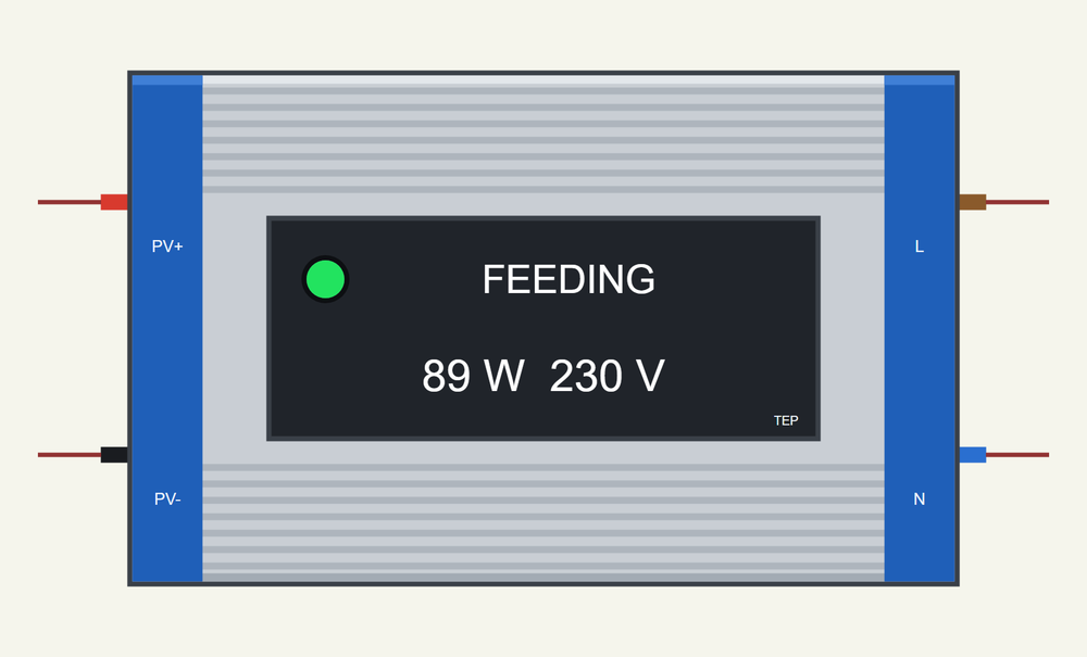
The inverter is MICROINVERTERTEP in TEPMICROINV.LIB, under Electromechanical > Inverters, with the prefix GT and the model TEPMICROINV.DLL. Search MICROINVERTER in Pick Devices. It has four pins: PV+ and PV- on the left, L and N on the right; the two sides are not connected inside. The properties are MAXW, the rated power (300), and WAIT, the seconds it watches a good grid before it feeds in (3; a real inverter waits a minute or more).
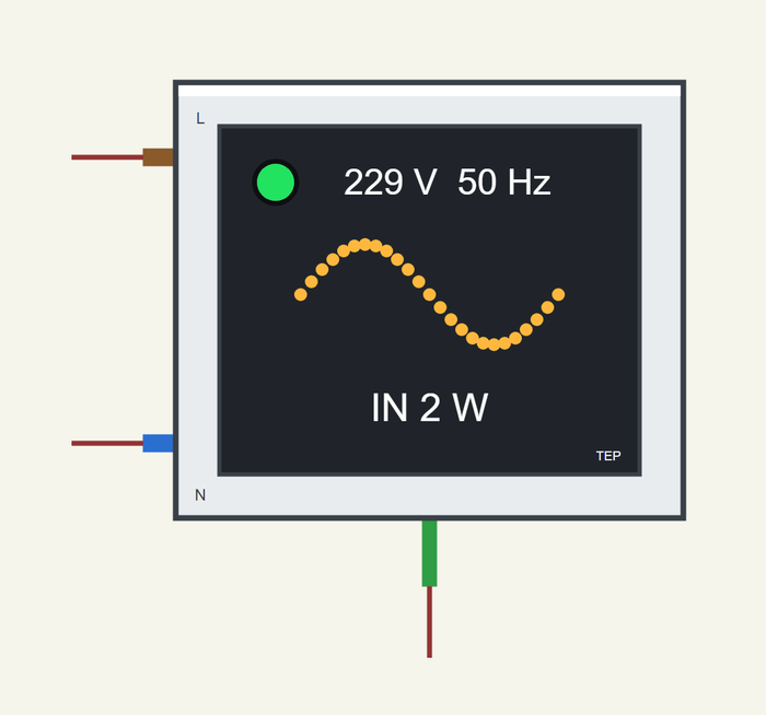
The mains is MAINSGRIDTEP in TEPMAINS.LIB, under Simulator Primitives > Sources, with the prefix AC and the model TEPMAINS.DLL. Search MAINSGRID. It has three pins: L, N and ON. Leave ON open and the grid is always there; pull it low, with an Arduino pin for example, and the power is cut. The properties are VOLTS (230), HZ (50), LINE, the resistance of the line (0.4 ohm), and START (ON or OFF).
In the demo the panel comes from our 12V Solar Panel Library for Proteus.
Download Grid-Tie Micro Inverter Library for Proteus Simulation
Click the button below to download Grid-Tie-Micro-Inverter-Library-for-Proteus-v1.0.zip (about 1.9 MB, without the source code of the models):
Grid-Tie Micro Inverter Library for Proteus V1.0- README.txt: installation, the demo, the wiring, troubleshooting and the limits of the simulation.
- Proteus Library Files:
TEPMICROINV.LIB,TEPMAINS.LIB,TEPSOLAR.LIBandArduinoV4TEP.LIB. - Proteus Model Files:
TEPMICROINV.DLL,TEPMAINS.DLL,TEPSOLAR.DLLandTEPARDUINO.DLL. - Arduino Code: the demo sketch.
- Proteus Simulation: the demo project, its HEX file and copies of the DLLs.
No Proteus yet? Read How to Download and Install Proteus 7 and 8. New to libraries? Follow How to Install a New Library in Proteus.
How to Install Grid-Tie Micro Inverter Library for Proteus Simulation
- Close Proteus and extract the whole zip file, for example to your Desktop.
- Copy the files from Proteus Library Files into the LIBRARY folder of Proteus.
- Copy the files from Proteus Model Files into the MODELS folder.
- Delete
TEPMICROINV.IDXfrom the LIBRARY folder if it is there. - Start Proteus, press P and search for MICROINVERTER.
Proteus Simulation of an Island Test with Arduino
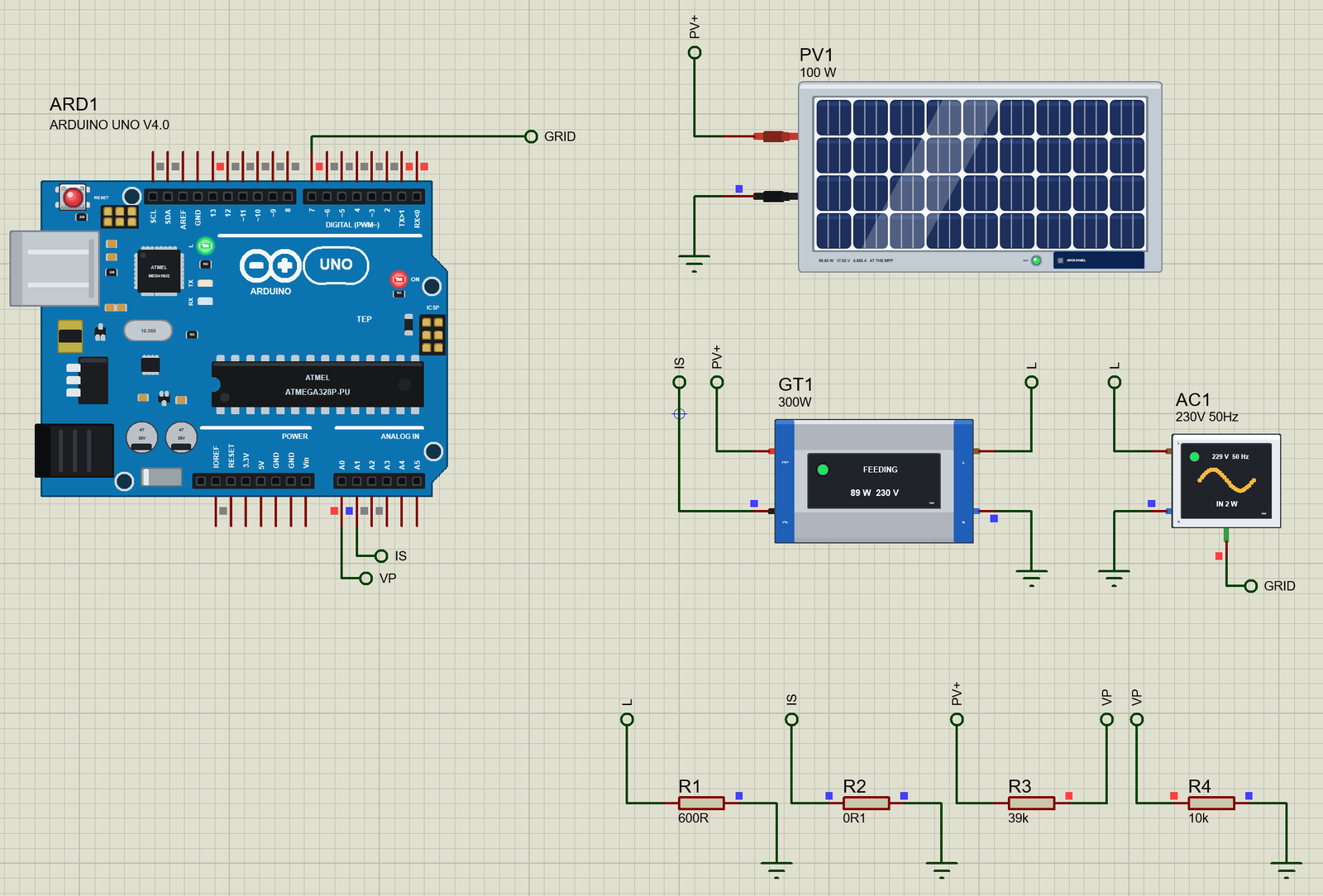
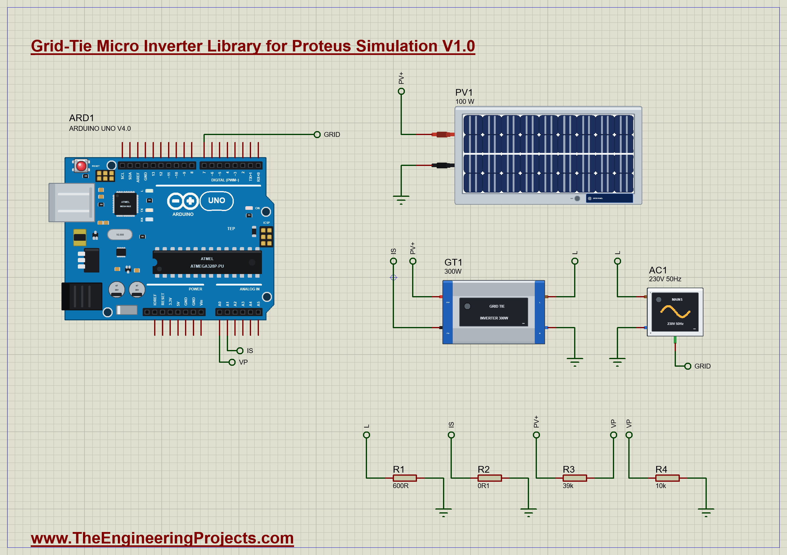
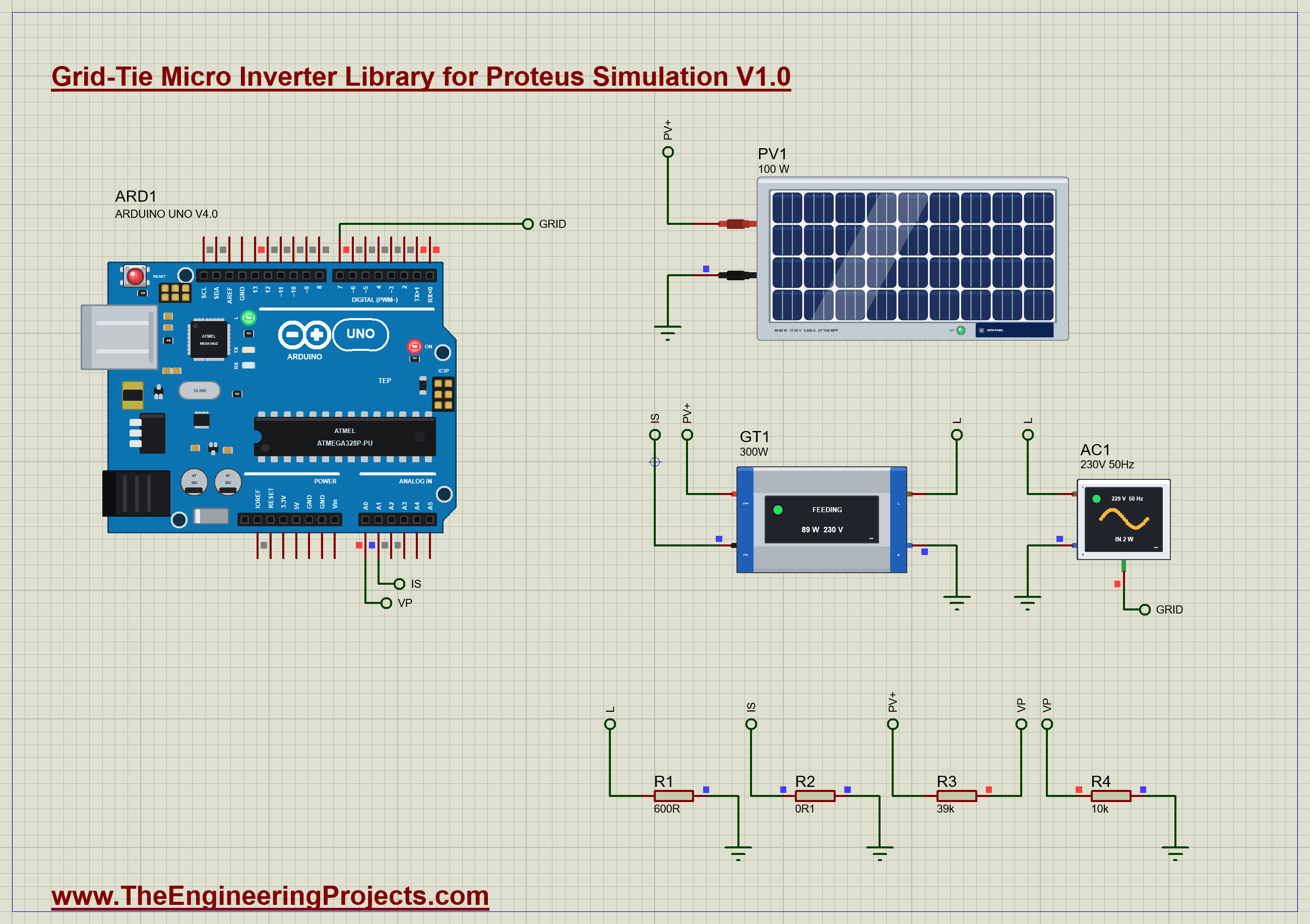
The demo is a tiny solar house with a test bench around it. PV1, a 100 W panel of our 12V Solar Panel library in full sun, feeds the inverter GT1. On the other side the inverter hangs on the label L together with the mains AC1, 230 V and 50 Hz, and with R1, a resistor of 600 ohm that stands for the house: it takes 88 W at 230 V, just about what the inverter gives. That is on purpose: it is the hardest case for the island protection. The N pins are on ground, the earthed neutral.
Our Arduino UNO Library for Proteus V4.0 stays on the safe, low-voltage side. R2, a shunt of 0.1 ohm in the PV- wire of the inverter, turns the panel's current into a small voltage for A1; R3 of 39k and R4 of 10k divide the panel's voltage for A0. Pin 7 goes to the ON pin of the mains: with it the Arduino can cut the power. The inverter's WAIT is 2 seconds. The Arduino's built-in monitor is the same window as our TEP Serial Monitor Advance for Proteus. Open Grid-Tie-Micro-Inverter-Island-Tester-ArduinoUnoV4.pdsprj.
The Sketch
The sketch never touches the mains side. It knows that the inverter is feeding in because the inverter then takes current from the panel:
if (!feeding && amps > FEED_AMPS) feeding = true; else if (feeding && amps < IDLE_AMPS) feeding = false;Pin 7 holds the grid on. The order of the two calls matters: first the level, then the direction, so that the pin never dips low and the power is never cut by accident:
digitalWrite(PIN_GRID, HIGH); pinMode(PIN_GRID, OUTPUT); // high first, then an output: no low glitch, the grid stays onFive seconds after the start comes the test, a power cut of two seconds:
void powerCut() {
  digitalWrite(PIN_GRID, LOW); cut = true; cutAt = millis(); waitStop = feeding;
  Serial.println(F("TEST: a power cut"));
}
From then on the sketch watches the panel's current. The moment it falls away, the inverter has stopped, and the time since the cut is printed:
if (!feeding && was && waitStop) { Serial.print(F("the inverter STOPPED ")); Serial.print(now - cutAt); Serial.println(F(" ms after the cut")); waitStop = false; }You can type cut for another power cut at any time.
Grid-Tie Inverter Simulation Results
Open the project and press Run. The demo runs 10.5 simulated seconds. The mains needs small time steps, a tenth of a millisecond, so with the pop-ups open and the pictures being taken it took 140 seconds on our PC. Click the inverter and the mains for their pop-ups. Every number below comes from one simulation run, the demo exactly as it ships.
Watching the Grid
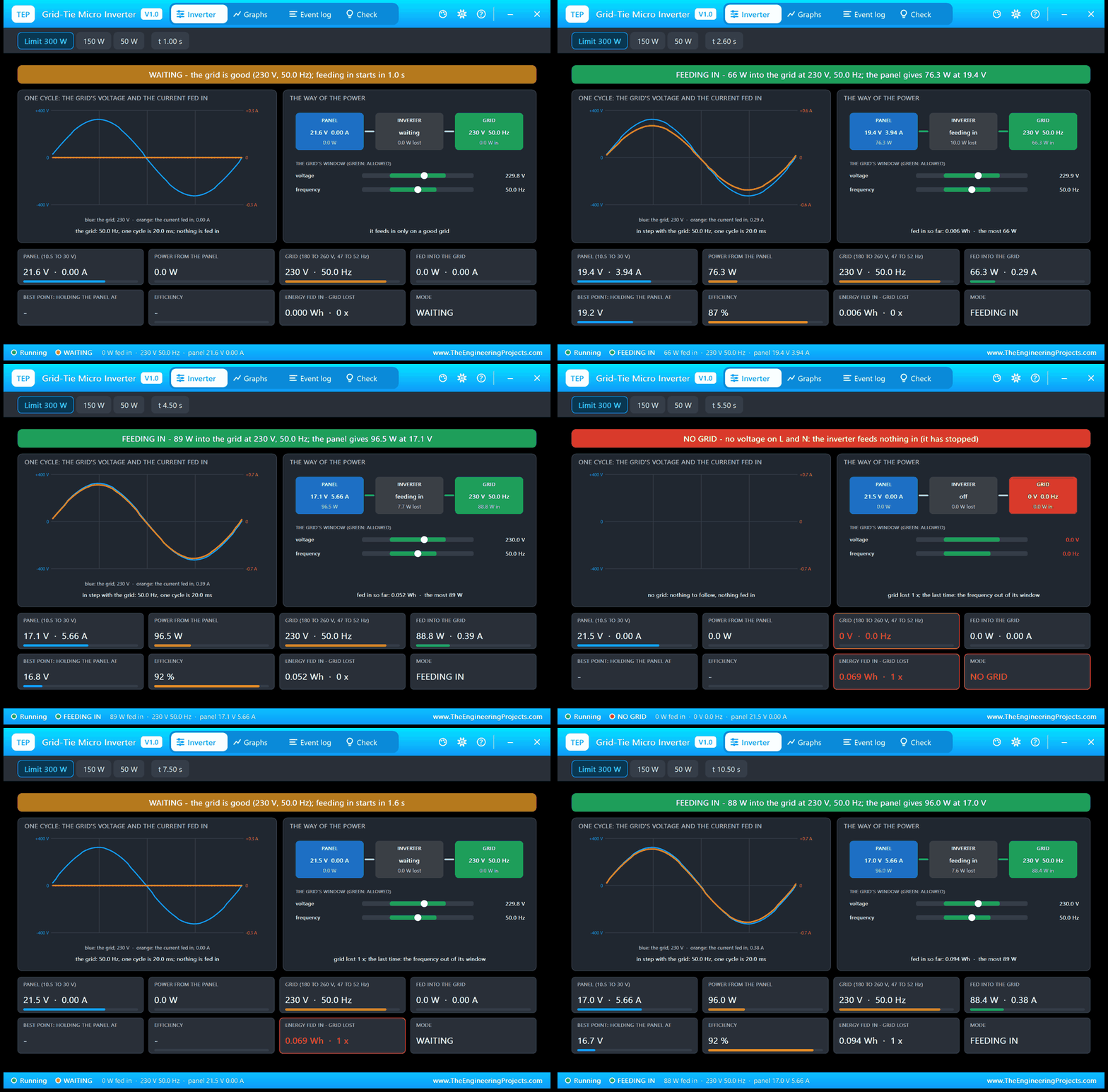
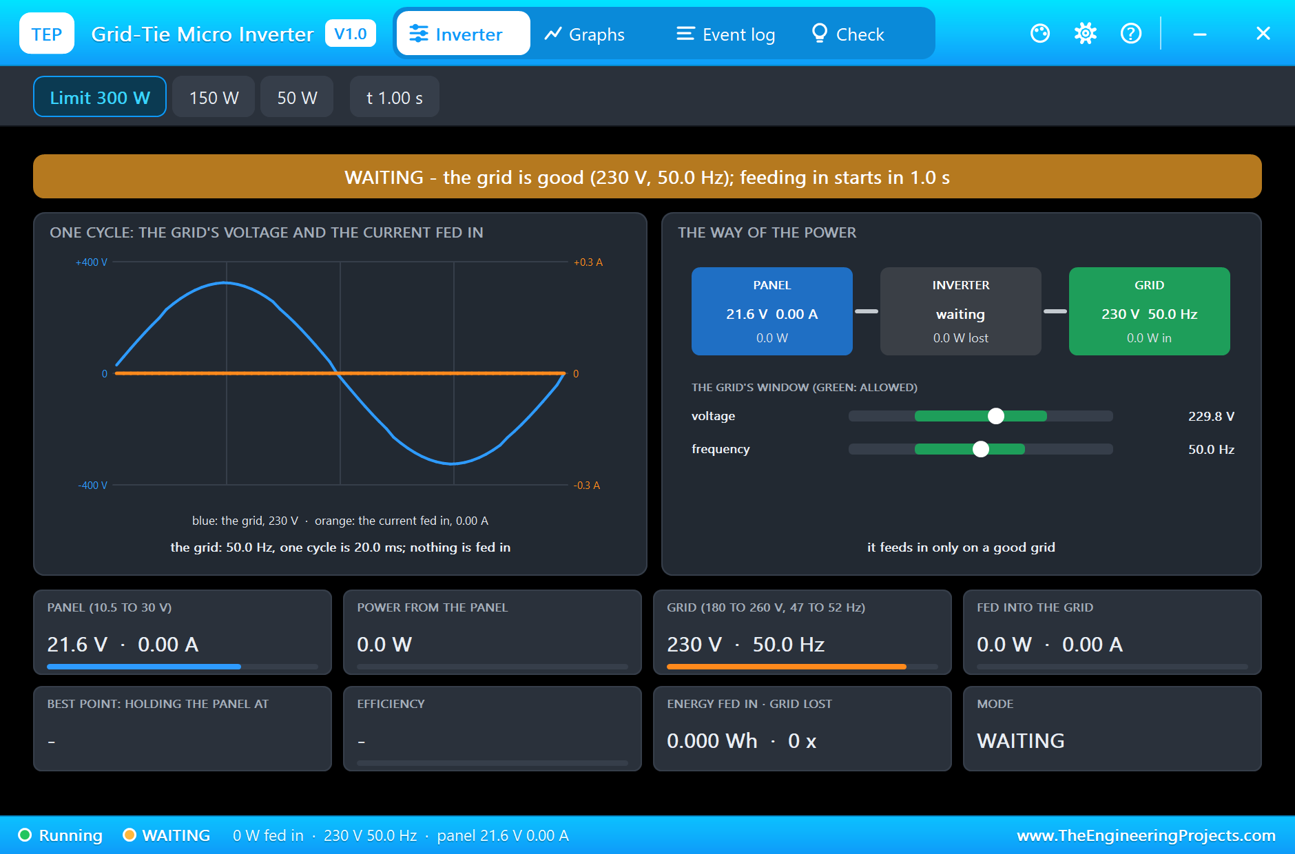
After one second the inverter's banner is amber: WAITING. It has measured the grid, 230 V and 50.0 Hz, found it good, and now watches it; feeding in starts in 1.0 s. The left card shows one cycle of the grid in blue; the orange line of its own current is still flat. The panel stands open at 21.6 V.
Looking for the Best Point
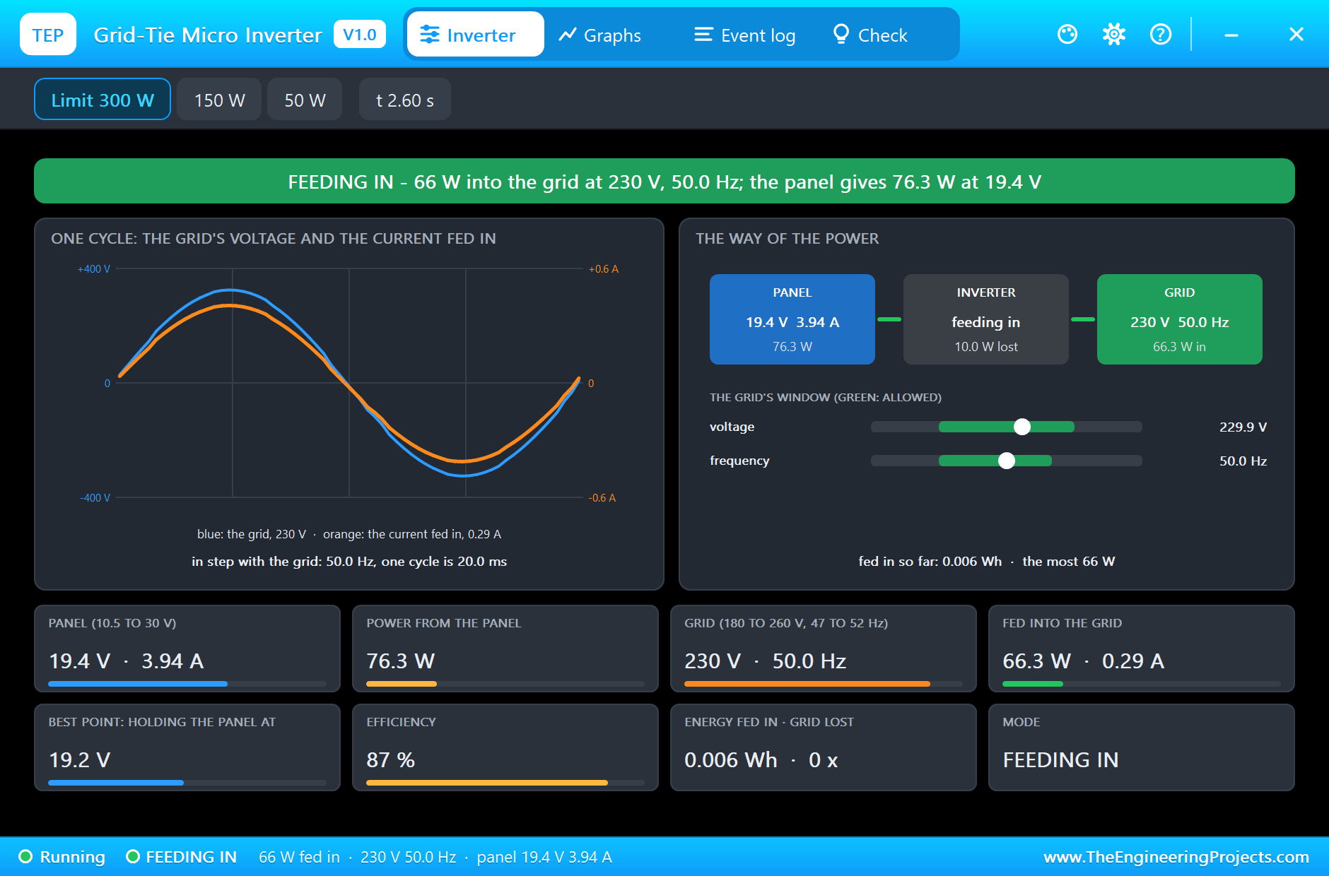
At 2.6 seconds the banner is green, FEEDING IN, and the inverter is on its way to the panel's best point. It started just under the open voltage and walks down in steps of 0.2 V, as long as each step brings more power. Now it holds the panel at 19.2 V; the panel gives 76.3 W at 19.4 V and 3.94 A, and 66 W flow into the grid. The orange current has appeared, smaller than it will be, but already exactly in step with the blue voltage.
Feeding In
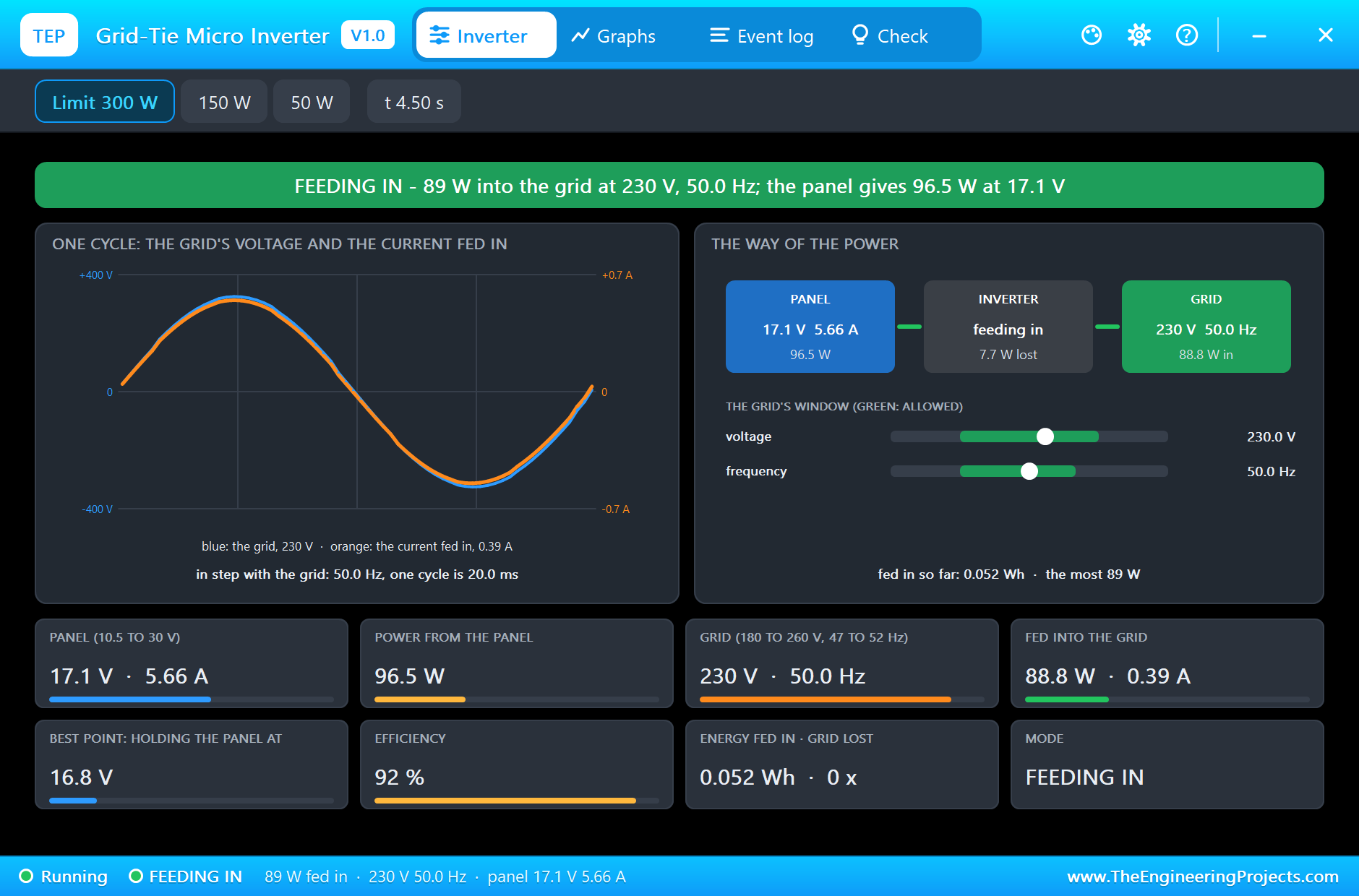
At 4.5 seconds the search has settled. The panel is held at 16.8 V and gives 96.5 W, 17.1 V at 5.66 A. The inverter feeds 89 W into the grid at 230 V and 50.0 Hz, a current of 0.39 A; 7.7 W are lost in it, an efficiency of 92 percent. On the right, the two markers of the grid's window sit in the green: 230.0 V and 50.0 Hz.
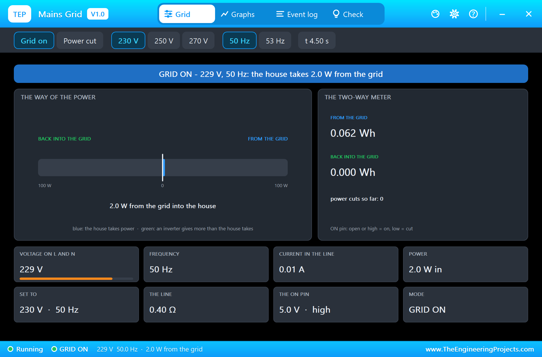
The pop-up of the mains shows the other end of the story. The house takes 88 W, the inverter brings almost all of it, and the grid has to add only 2.0 W.
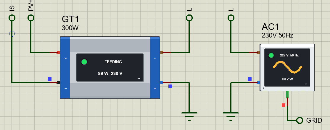
On the sheet the lamps of both parts are green; the inverter's plate says FEEDING and 89 W.
The Power Cut: an Island
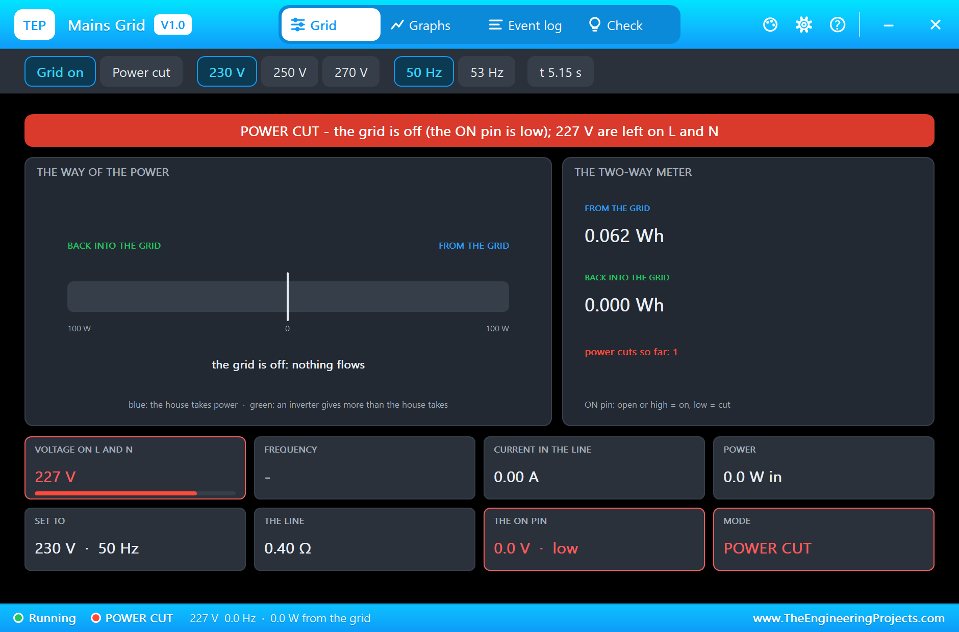
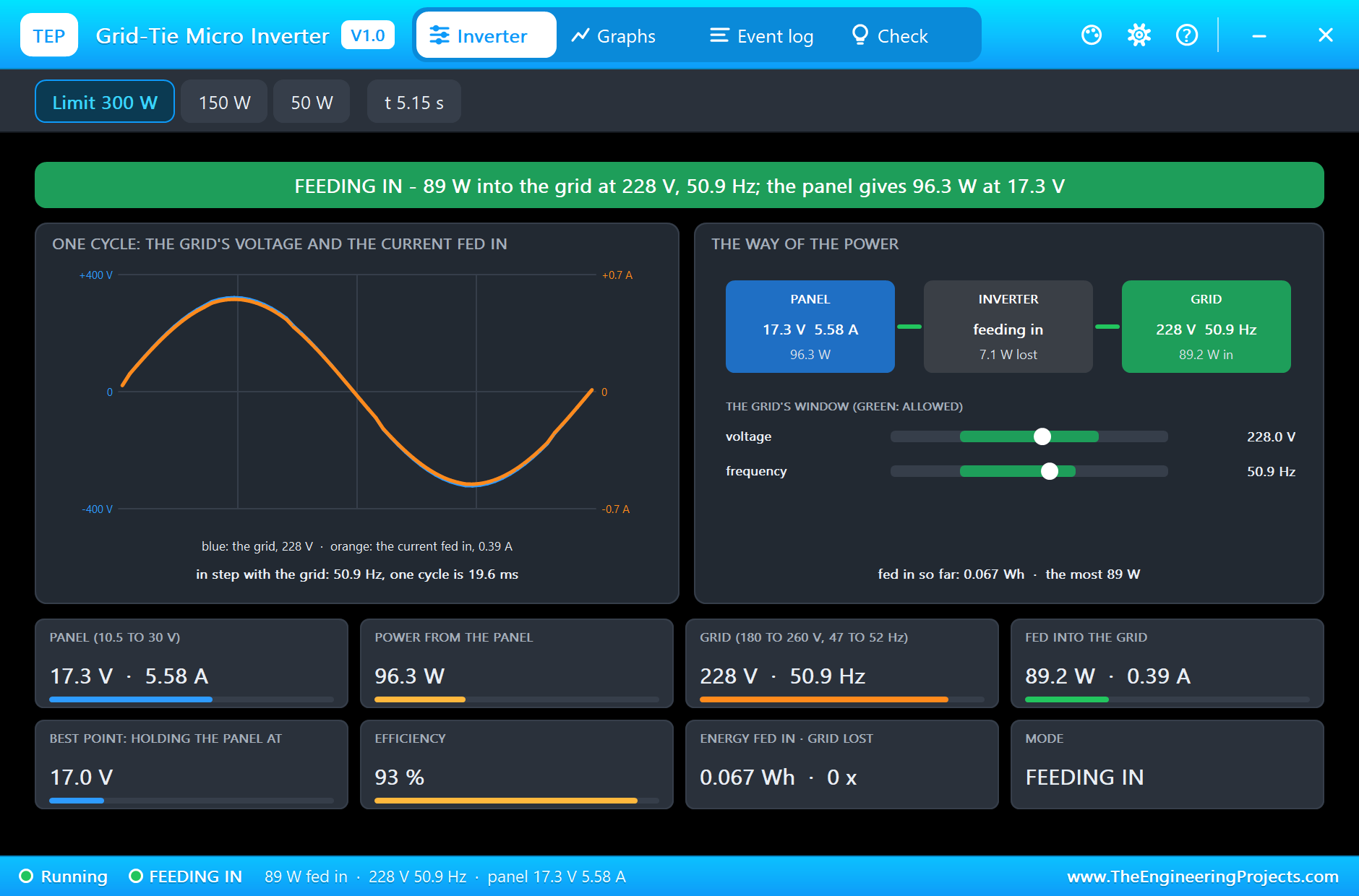
Five seconds after its start the Arduino pulls pin 7 low. The mains part reports a POWER CUT. But look at its banner: 227 V are left on L and N. The grid is gone, and the line is still live.
The inverter's pop-up, taken at the same moment, shows why. It is still FEEDING IN, 89 W at 228 V. The house load takes just what the inverter gives, so the voltage hardly moves; from the voltage alone nobody could tell that the grid has gone. This is the island. Only one number has changed: the frequency is 50.9 Hz, and its marker is wandering towards the edge of the window. Without a grid to pull it back, the inverter's slightly fast sine wave makes every cycle a little shorter than the one before.
The Inverter Stops
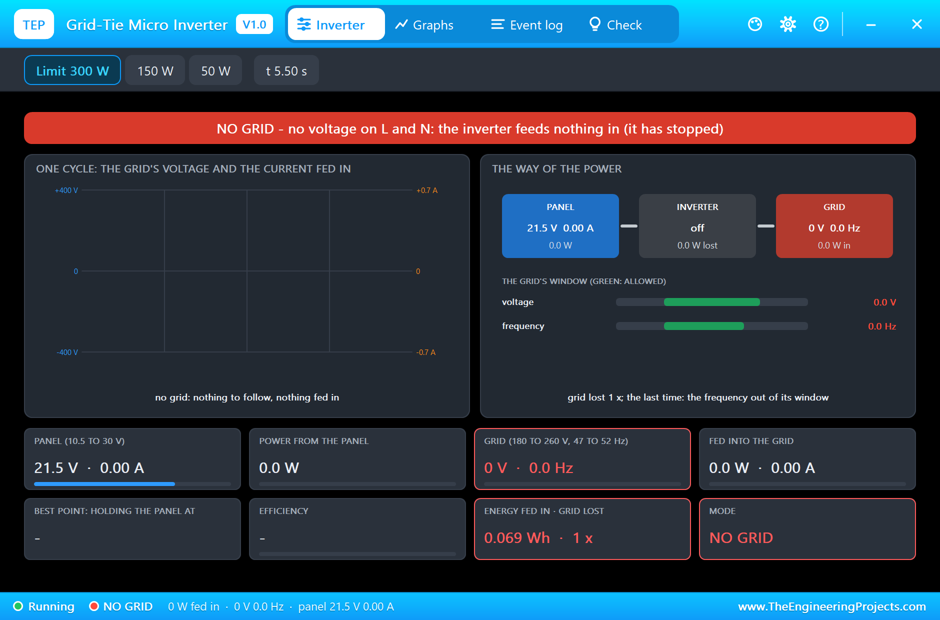
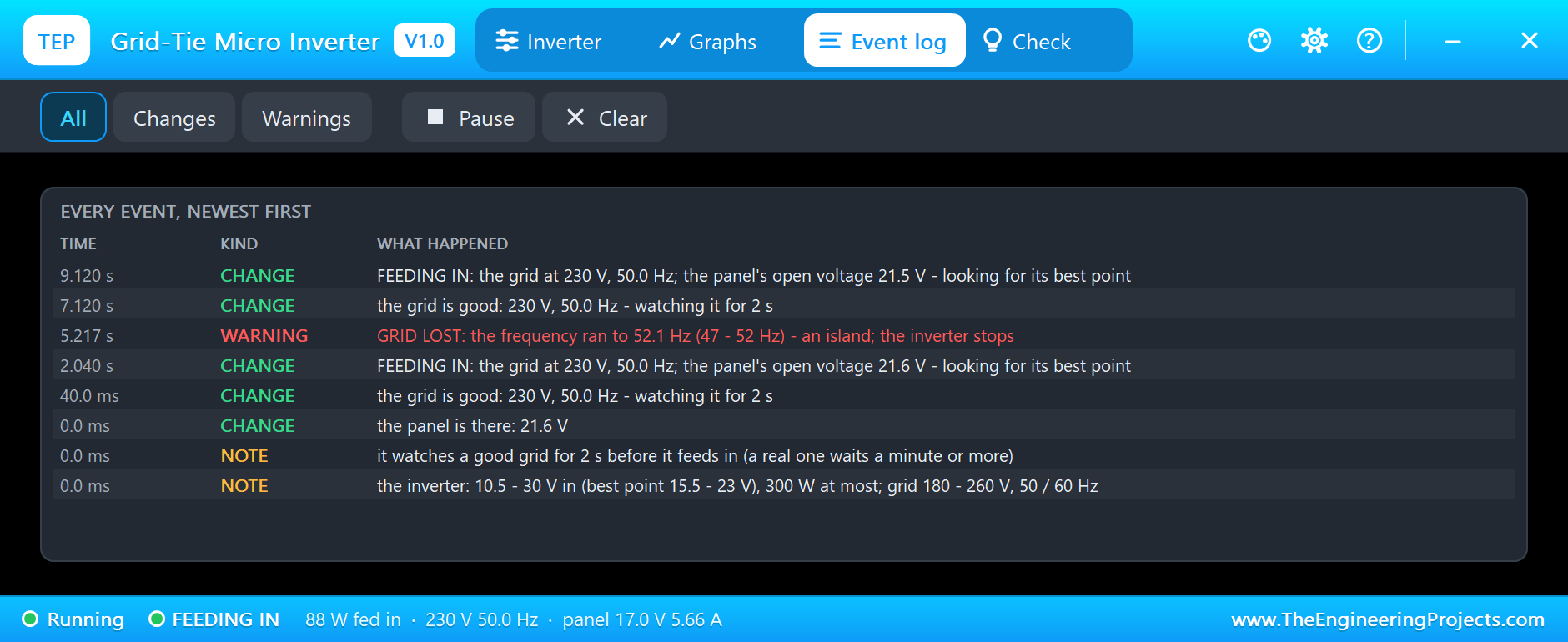
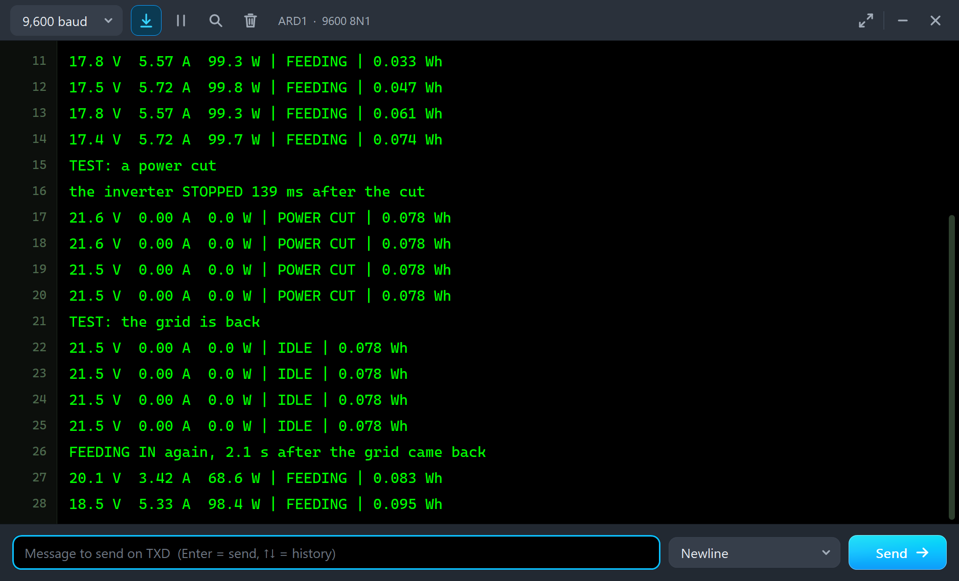
It does not take long. The Event log has the line: at 5.217 seconds, GRID LOST, the frequency ran to 52.1 Hz, an island, the inverter stops. The Arduino measured the same from the panel side and prints it in the monitor: the inverter STOPPED 139 ms after the cut. The banner is red, NO GRID, and the line is dead, as it must be.
The Grid Comes Back
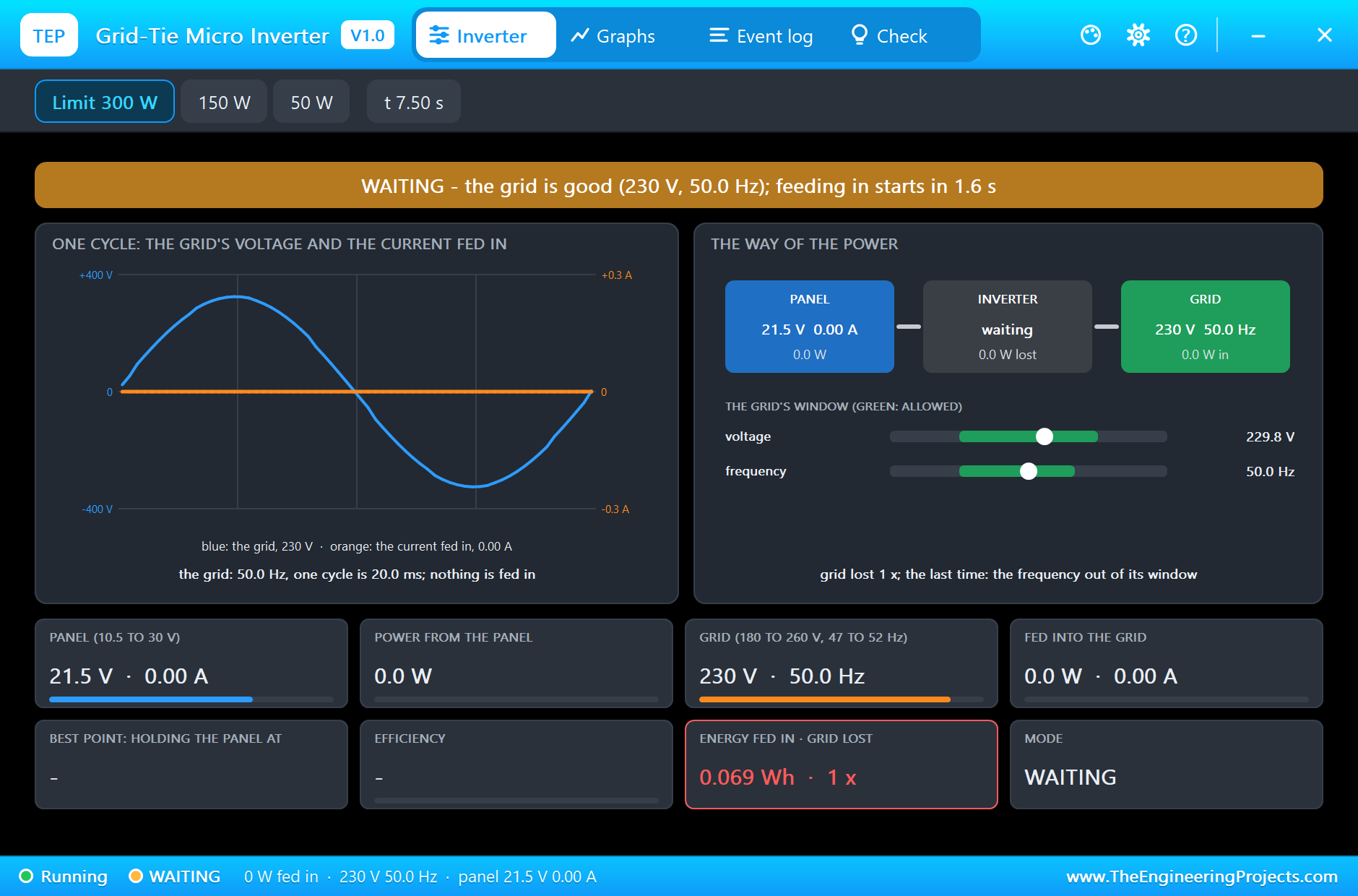
Two seconds later the Arduino lets the grid return. The inverter does not jump back in. At 7.5 seconds it is WAITING again, watching the grid for its 2 seconds.
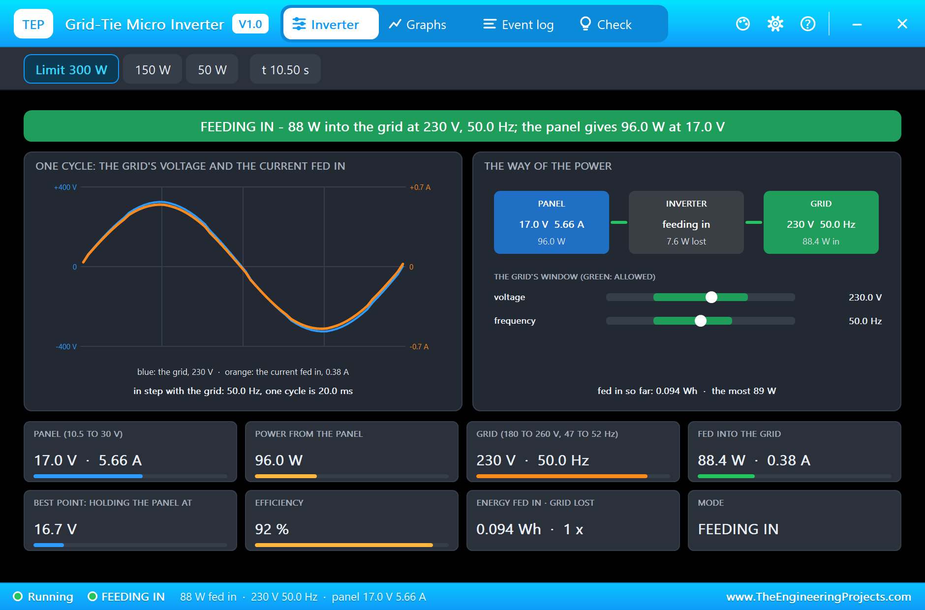
At 9.12 seconds the log notes FEEDING IN once more, and the monitor says: FEEDING IN again, 2.1 s after the grid came back. At 10.5 seconds the inverter is back at 88 W.
A Light Load: the Power Flows Back
For a second simulation run we changed the house load R1 to 2 k, only 26 W. Now the inverter gives more than the house takes, and the pop-up of the mains turns green: 59.4 W flow BACK into the grid. The two-way meter counts both directions.
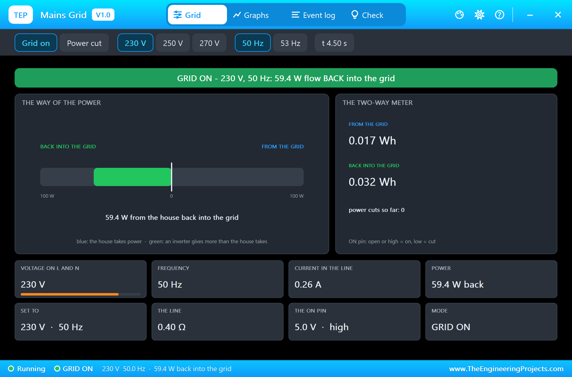
In this run the power cut ends differently. With so small a load left on the line, the inverter's current has nowhere to go; the voltage runs away, and the inverter stops at once, at 5.091 seconds. An island with too little load gives itself away by its voltage; an island with a matching load only by its frequency.
A Grid Outside Its Window
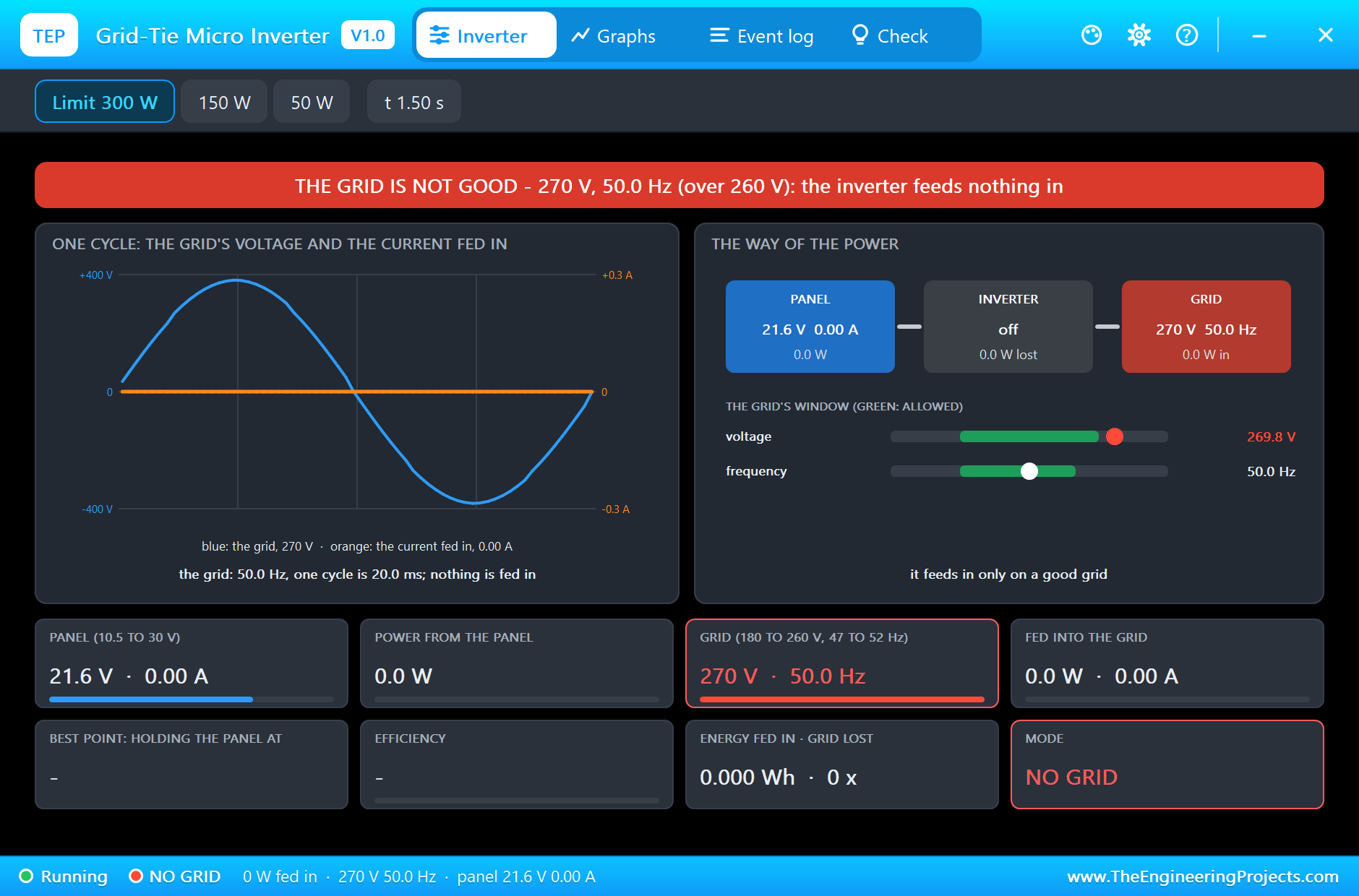
For a third run we set the mains to 270 V. The inverter measures it and refuses: THE GRID IS NOT GOOD, over 260 V. It feeds nothing in.
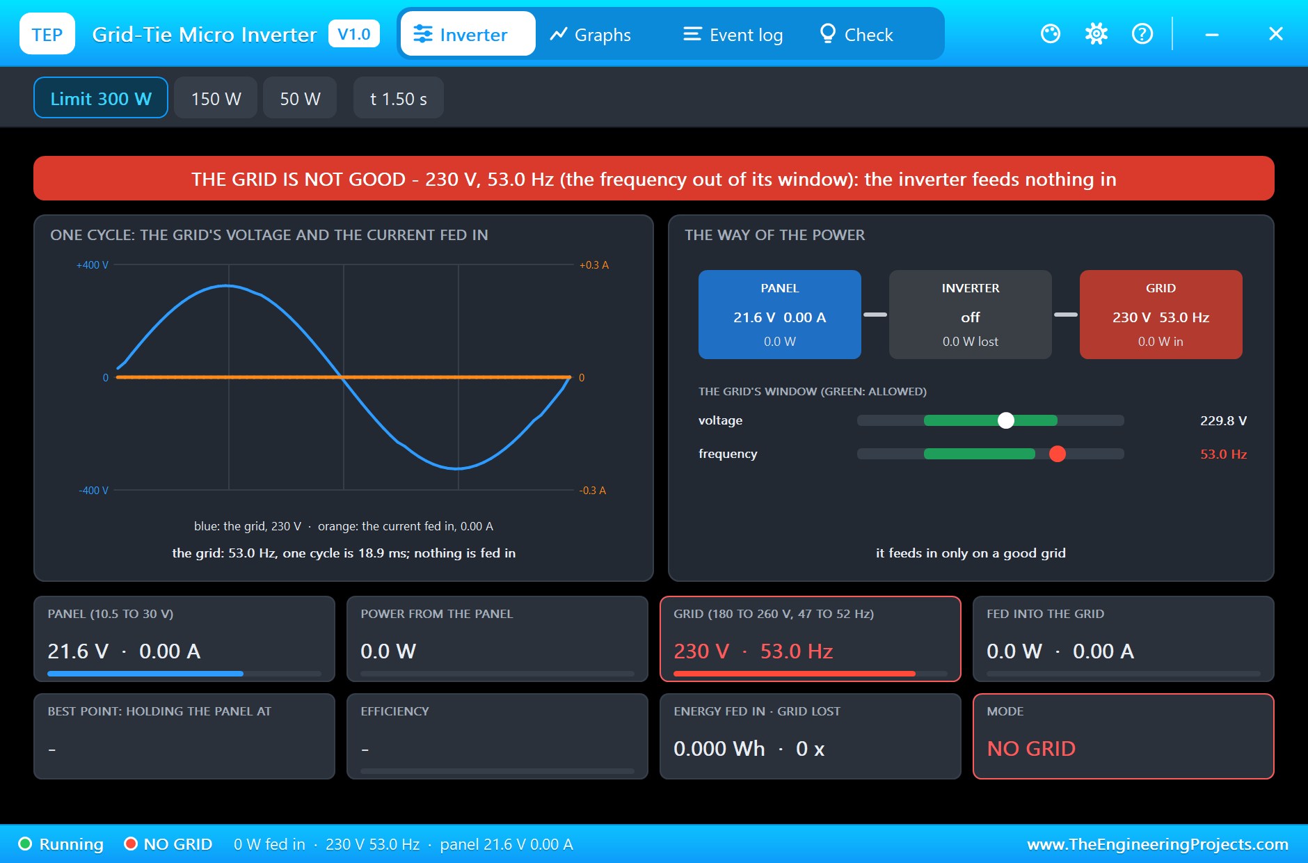
For a fourth run the mains has 230 V again, but 53 Hz. The answer is the same: the frequency is out of its window.
The Graphs, the Event Log and the Check Page
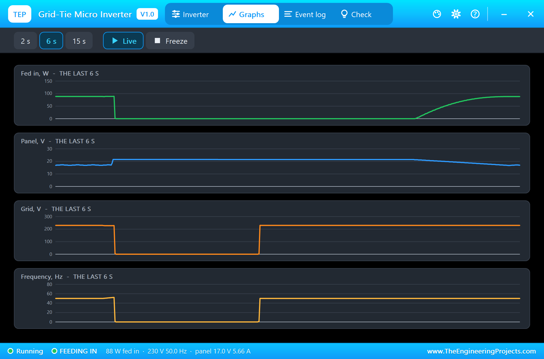
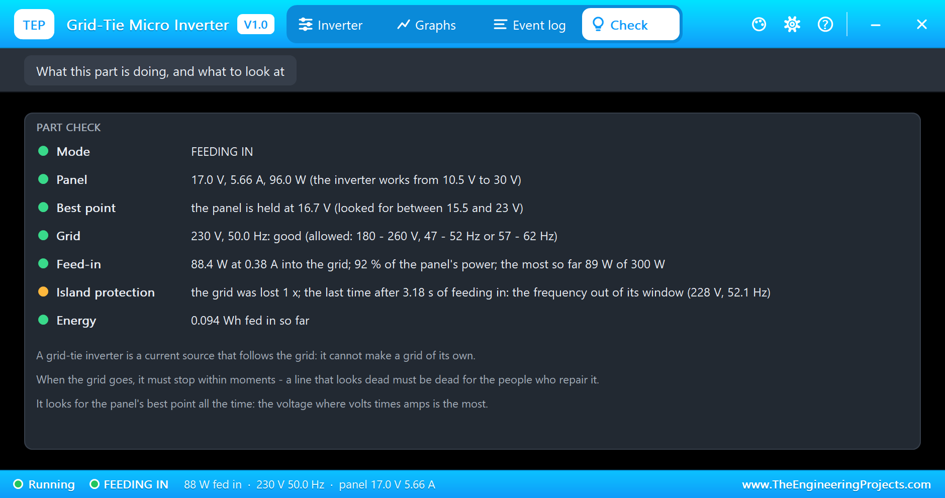
Back to the first run. The Graphs page plots the power fed in, the panel's voltage, the grid's voltage and the frequency over the last 2, 6 or 15 simulated seconds: the power climbing as the best point is found, the gap of the power cut, and the second climb. The Event log keeps every step with its time. The Check page sums up: the grid was lost once, after 3.18 seconds of feeding in, by the frequency (228 V, 52.1 Hz).
The monitor shows the test from the Arduino's side: FEEDING with about 99 W from the panel, TEST: a power cut, the inverter STOPPED 139 ms after the cut, four lines of POWER CUT, TEST: the grid is back, IDLE, and FEEDING IN again after 2.1 s. The Arduino reads a little more than the inverter's pop-up, because its voltage includes the drop across the shunt.
Try It Yourself
- Type
cutin the monitor: another power cut, and another measurement. - Click 250 V, 270 V or 53 Hz in the pop-up of the mains while the inverter feeds in, and watch it stop.
- Click 150 W or 50 W in the inverter's pop-up: it moves the panel off its best point to stay under the limit.
- Change R1 to 300 ohm: the house takes more than the sun gives, and the grid supplies the rest.
- Set the IRRADIANCE of the panel to 500 and compare the power fed in.
Ideas to Extend the Demo
- Count the energy on both sides and let the Arduino show the day's yield.
- Dim the sun through the day and log the power, as a real solar meter does.
- Add a second load with a switch and watch the way of the power turn around.
- Measure the stop time for different house loads and find the slowest case.
Your Own Sketches
The demo sketch is in the zip file, and you can change it in the Arduino IDE. New to Arduino? Start with our Arduino Tutorial for Beginners. Export the compiled binary, and set the UNO's PROGRAM property to the new file. Our guide on How to get the HEX file from Arduino shows you where the file ends up.
Things to Know Before Using a Real Grid-Tie Inverter
- It needs a grid: a grid-tie inverter is a current source that follows the mains. In a power cut it gives nothing, by design.
- Mains voltage kills: never open such an inverter and never touch L or N. The Arduino of the demo measures only the panel side.
- Ask first: in most countries feeding into the grid needs an approved inverter and the consent of the grid operator.
- It waits: a real inverter waits a minute or more before it feeds in, and again after every fault.
- Match the panel: the panel's best point must lie in the inverter's window, 15.5 to 23 V here, which is a 36-cell panel.
- No isolation, no connection: never connect an Arduino to the mains side without proper isolation.
Troubleshooting
- NO GRID: there is no voltage on L and N. The inverter needs the mains part, and the mains side needs a ground: put N on ground.
- THE GRID IS NOT GOOD: the voltage is outside 180 to 260 V or the frequency outside 47 to 52 Hz.
- It waits and waits: every fault starts the wait again. Look at the Event log.
- NO PANEL POWER: under 10.5 V on PV+ and PV-.
- The power is cut right at the start: the ON pin of the mains is low. In a sketch, write the pin high before you make it an output.
- The simulation is slow: the mains needs small time steps. Ten seconds take a couple of minutes.
- A part is not simulated:
TEPMICROINV.DLLorTEPMAINS.DLLis missing from MODELS and from the project folder.
Limitations of the Simulation
- The figures 10.5 to 30 V, 15.5 to 23 V for the best point, 300 W and 180 to 260 V at 50 or 60 Hz are sellers' figures for small inverters of this kind; no single maker's data sheet stands behind them.
- Our own figures: 93 percent efficiency, 0.6 W for the inverter itself, the 0.3 Hz of frequency drift, the windows of 47 to 52 Hz and 57 to 62 Hz, the 30 ms without a zero crossing, and the short WAIT.
- It is a mean-value model: nothing switches at 20 kHz, and the current is a clean sine wave.
- Not modelled: harmonics, reactive power, the heat of the inverter, its consumption at night, a 120 V version.
- The mains part is an ideal sine wave behind a resistance; its ON pin is ours, a help for tests.
- Both parts are drawn small and compact.
- Arduino is a name of Arduino; this library is not made or endorsed by Arduino, Labcenter or any maker of inverters.
- Tested in Proteus 8.5 in November 2026 (the demo as shipped). Proteus 7 is not supported.
So, that was all about the Grid-Tie Micro Inverter Library for Proteus Simulation, and with it our renewable energy series is complete. I hope it helps you understand how a solar inverter follows the mains, and why it must let go the moment the mains is gone. If you have any questions, ask in the comments and I will help you out. Till the next tutorial, take care and have fun!

Comments
0