


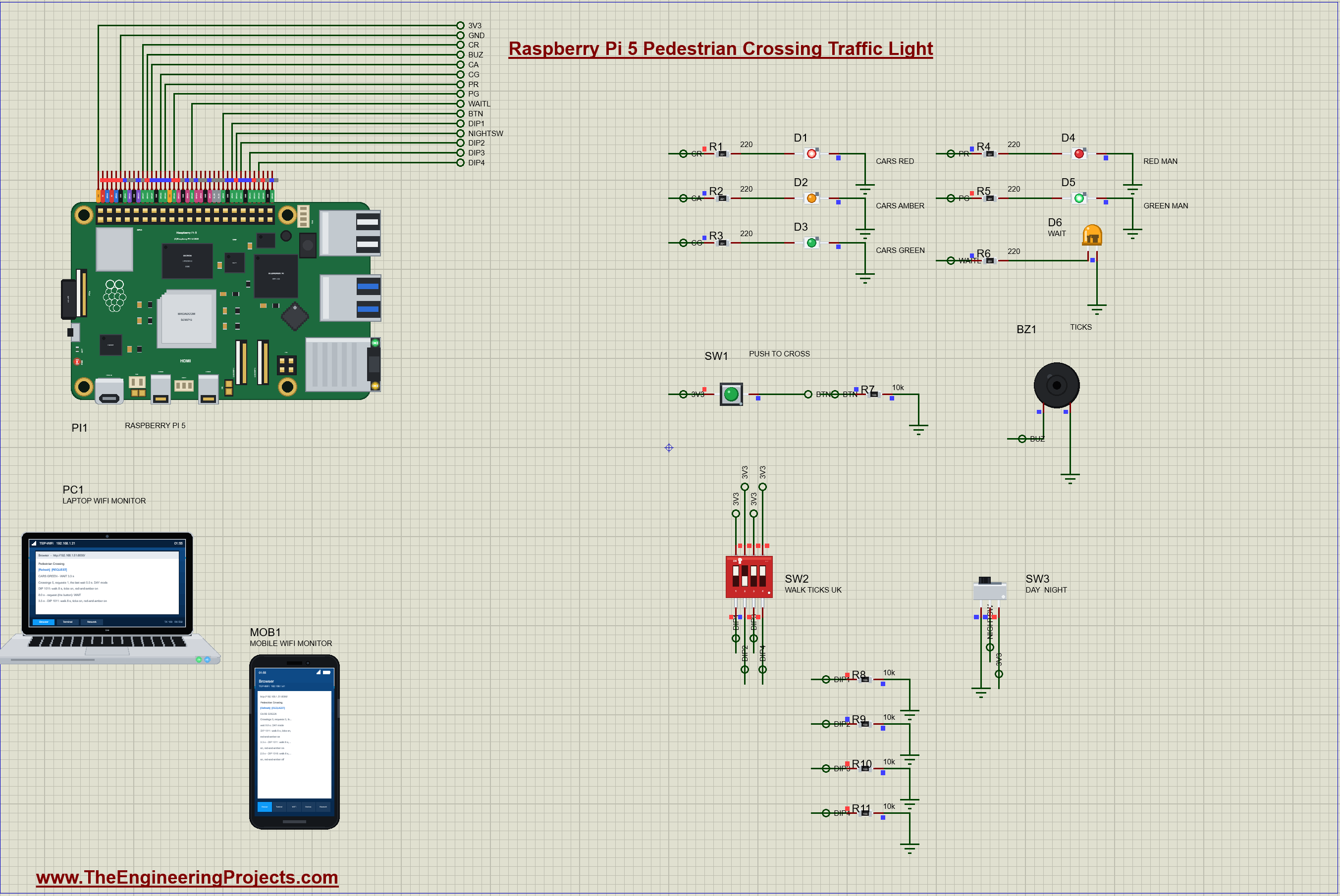
Raspberry Pi 5 Pedestrian Crossing Traffic Light (Proteus Simulation)


Hello friends, I hope you all are doing great. Today, I am going to share the Raspberry Pi 5 Pedestrian Crossing Traffic Light (Proteus Simulation), the fiftieth project of our IoT Projects series. If you have searched for a traffic light controller in Python, a Raspberry Pi traffic light project with a push button, or a Proteus simulation of a real pedestrian crossing, here is a complete one. A Raspberry Pi 5 runs the cars' red, amber and green lights and the red and green man, lights a WAIT lamp when someone presses the button, ticks a buzzer for blind people while they may cross, takes its timings from a DIP switch, flashes amber at night, and serves a web dashboard with a REQUEST button for a laptop or a phone.
A pedestrian crossing looks simple: a button and a few lamps. But every step of its sequence is there for a reason, and the timings are chosen from how fast people walk and how fast cars stop. In this tutorial, we will go through the circuit, see why a crossing has an amber, an all-red and a minimum green, work out a walk time and a clearance time from the width of a road, read a 4-way DIP switch as a binary number through pull-down resistors, use a slide switch for DAY and NIGHT, read a bouncing push button, run the sequence as a state machine in its own thread, walk through the Python program, and then run the simulation: a crossing by day with the ticks and the red-and-amber step, the night mode, and a night crossing requested from the laptop. At the end, you can download the project with the program and every library file.
NOTICE: Our team has put a lot of effort into this project: the circuit, the code and every part in the simulation are our own work, and you get them all free. Your feedback is the fuel that keeps us going, so please tell us what you think in the comments below. And if our free projects help you, you can buy us a coffee. So, let's get started with the Raspberry Pi 5 pedestrian crossing in Proteus simulation:
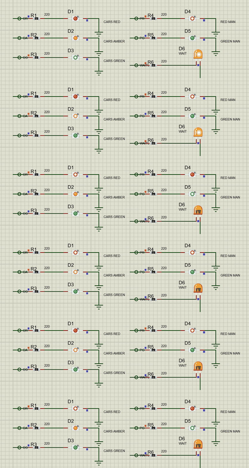
What Does This Pedestrian Crossing Do?
- Keeps the traffic moving: the cars have green until someone presses PUSH TO CROSS, and always at least 20 seconds of green between two crossings.
- Tells the walker it heard them: the WAIT lamp lights at the first press and stays on until the green man.
- Stops the cars safely: amber for 3 seconds, then red, then 1 second of all red before the green man.
- Helps blind people: the buzzer ticks fast while the green man is lit and goes quiet when it starts to flash.
- Clears the road: the green man flashes for 4 seconds (do not start to cross), then the red man and, if chosen, red and amber for the cars.
- Set on site: a 4-way DIP switch chooses the walk time (6, 8, 10 or 12 seconds), the ticks and the red-and-amber step.
- Night mode: a slide switch makes the cars' amber flash; a press still gets a full crossing.
- A web dashboard: the state, the wait, the crossings and the settings, with REQUEST, on a laptop or a phone.
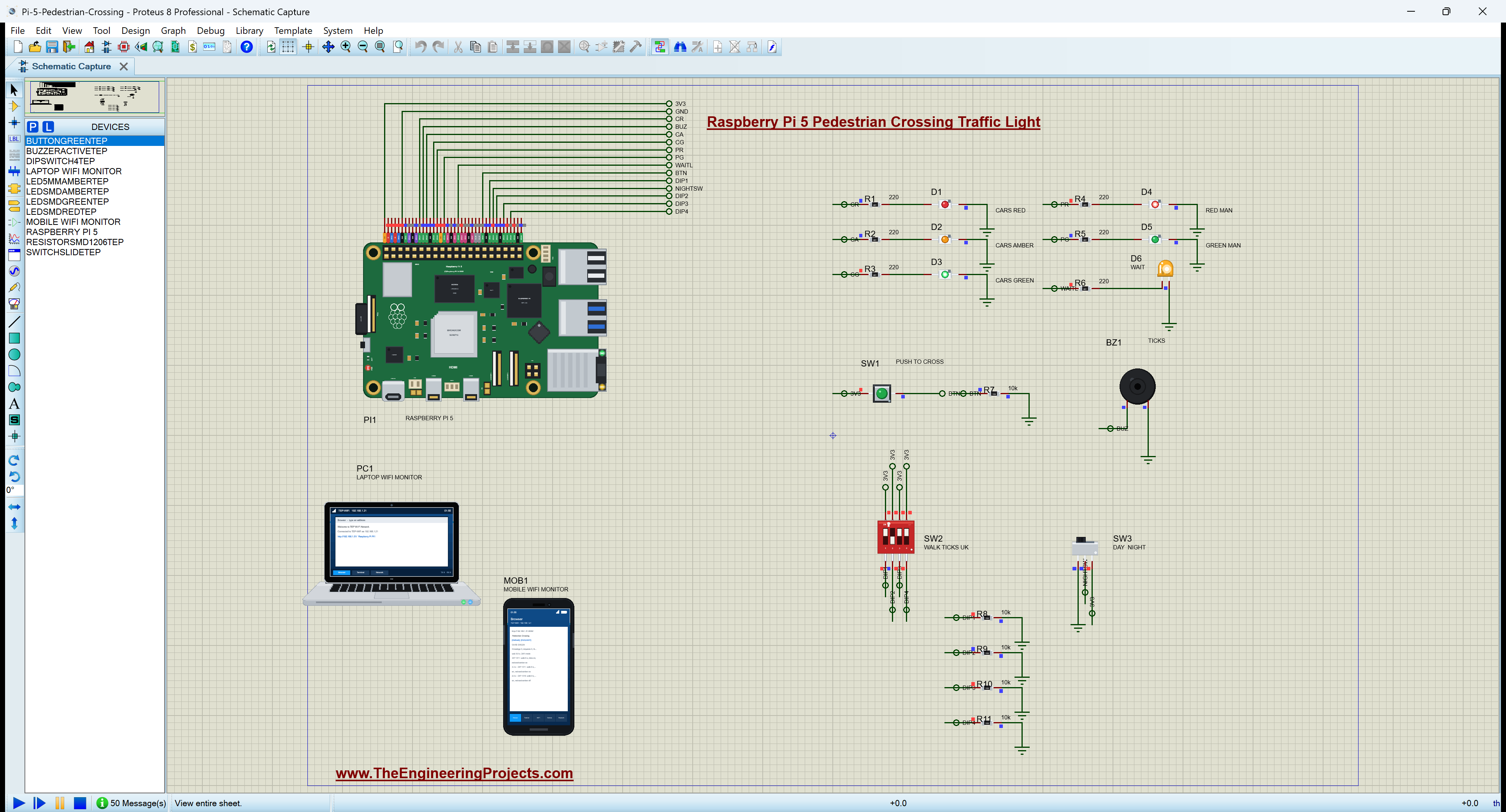
It is a great project for learning GPIO outputs and inputs from Python, pull-down resistors, reading switches as numbers, debouncing a button, threads and a state machine, and a little traffic engineering. In the simulation, the push button's pop-up shows each press with its contact bounce, the DIP switch's pop-up shows which switches are on, the slide switch's pop-up shows where its contact is, the buzzer's pop-up shows every tick, and the SMD LEDs light on the sheet exactly as the program drives them.
Components Used in the Proteus Simulation
All the parts come from our Proteus libraries, each with its own tutorial. The project zip at the end includes every LIB and DLL file and the TEPPi Python runtime.
| Part | Proteus device | Library post | Connection |
|---|---|---|---|
| Raspberry Pi 5 | RASPBERRY PI 5 | Raspberry Pi 5 Library for Proteus | PI1, Ethernet 192.168.1.51 |
| SMD LEDs, the cars | LEDSMDREDTEP, LEDSMDAMBERTEP, LEDSMDGREENTEP | SMD LED Library | D1 - D3, GPIO17, 27, 22 |
| SMD LEDs, the people | LEDSMDREDTEP, LEDSMDGREENTEP | SMD LED Library | D4 red man GPIO23, D5 green man GPIO24 |
| 5 mm amber LED | LED5MMAMBERTEP | Designer Colour LED Library | D6, the WAIT lamp, GPIO25 |
| SMD resistors 1206 | RESISTORSMD1206TEP | SMD Resistor Library | R1 - R6 220 ohm, R7 - R11 10 kohm |
| Push button | BUTTONGREENTEP | Push Button Library | SW1, PUSH TO CROSS, GPIO5 |
| 4-way DIP switch | DIPSWITCH4TEP | DIP Switch Library | SW2, GPIO6, 13, 19, 26 |
| Slide switch | SWITCHSLIDETEP | Slide Switch Library | SW3, DAY / NIGHT, GPIO12 |
| Active buzzer | BUZZERACTIVETEP | Active Buzzer Library | BZ1, the ticks, GPIO18 |
| Laptop WiFi Monitor | LAPTOP WIFI MONITOR | Laptop WiFi Monitor | PC1 |
| Mobile WiFi Monitor | MOBILE WIFI MONITOR | Mobile WiFi Monitor | MOB1 |
The five signal lamps are tiny SMD LEDs, and all eleven resistors are 1206 SMD chips, which keeps the whole crossing compact on the sheet; the WAIT lamp is a bigger 5 mm amber LED, the way the WAIT sign on a real crossing box stands out from the signals.
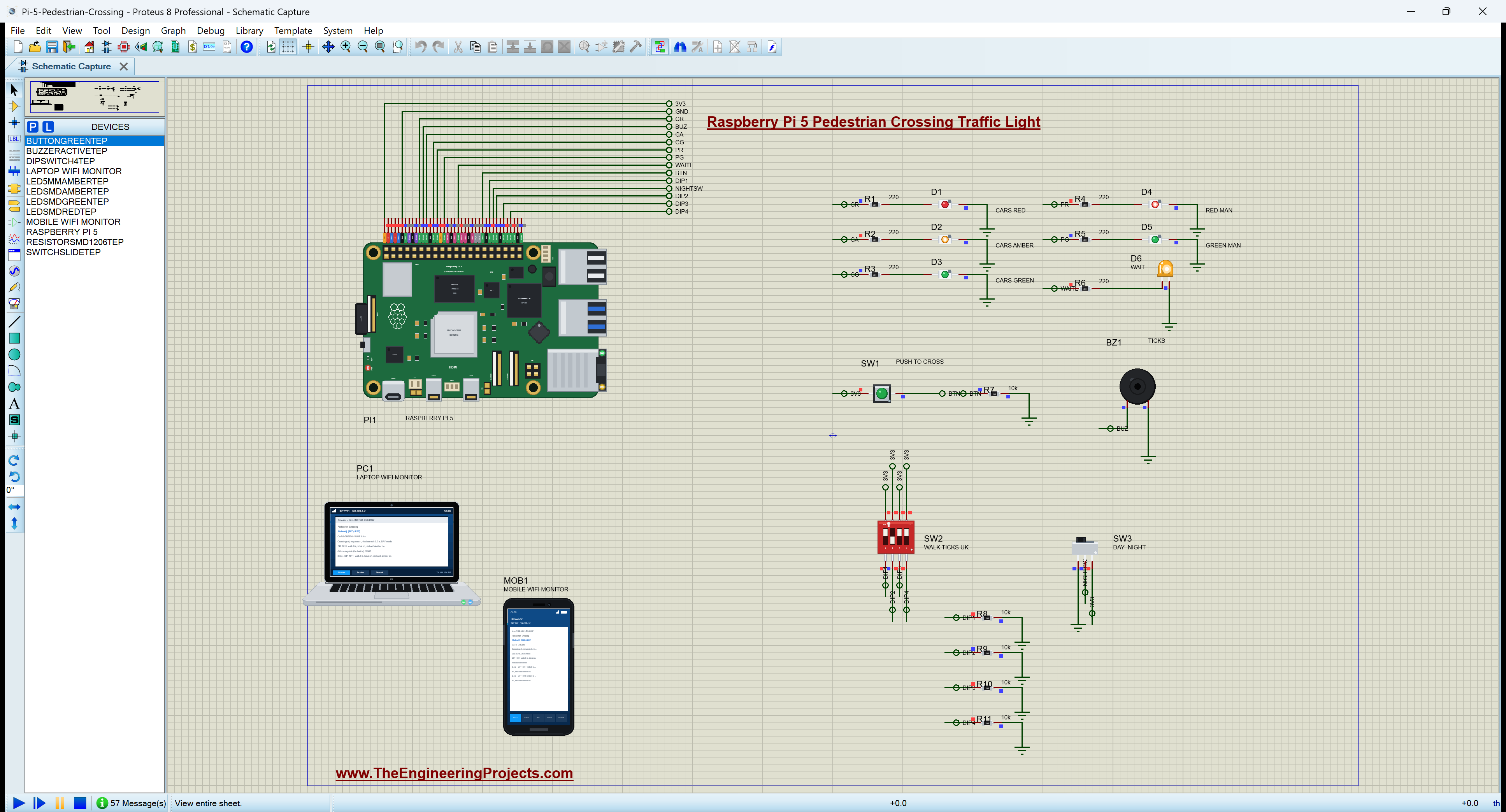
Proteus Simulation of the Pedestrian Crossing: the Circuit
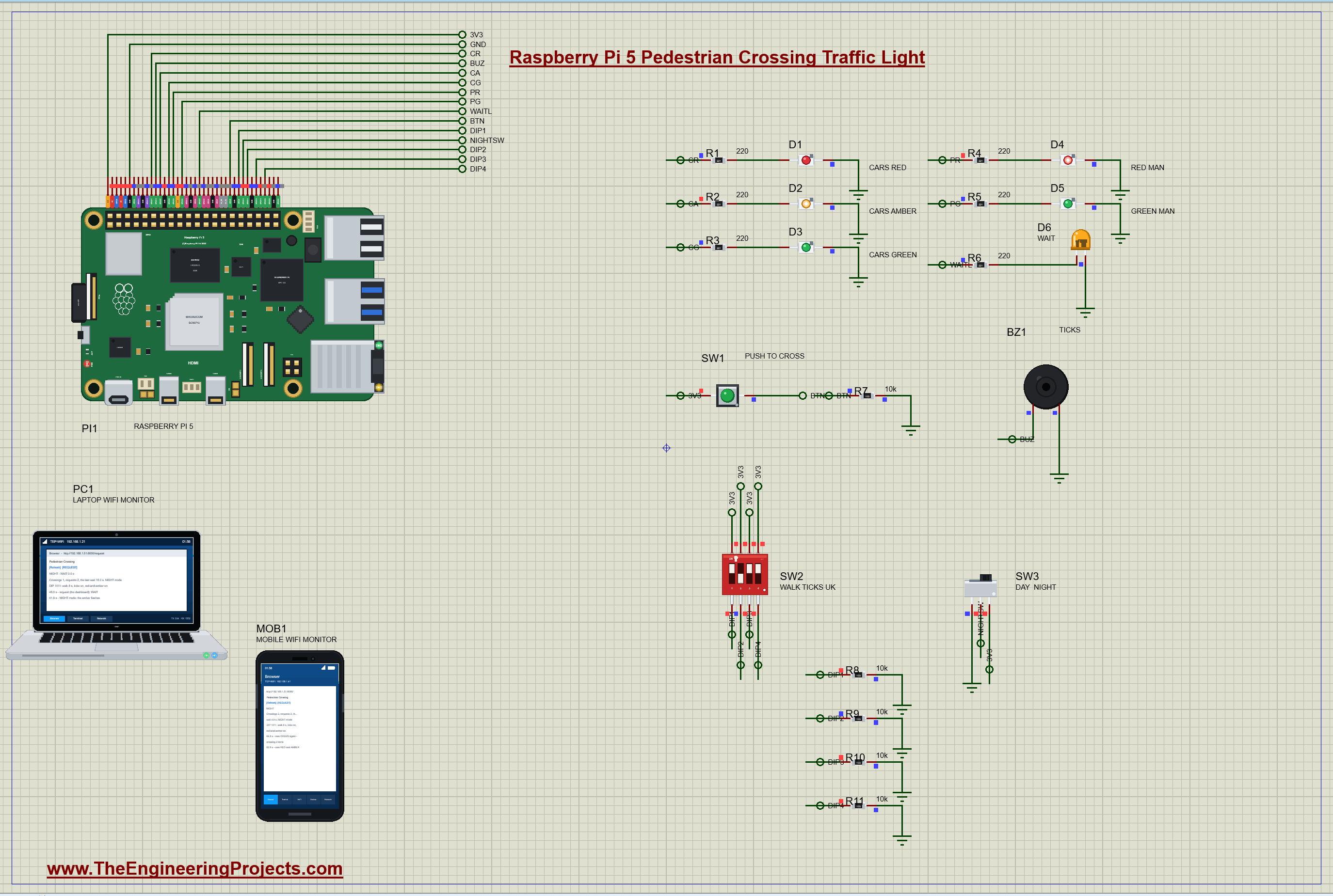
| Part | Pins | Raspberry Pi 5 / other |
|---|---|---|
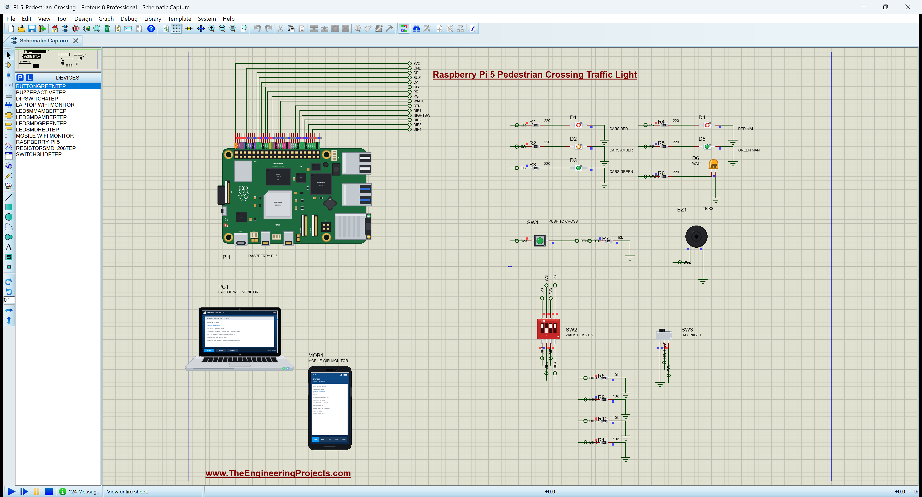
| D1, D2, D3 the cars | A through R1 - R3 (220 ohm) / K | GPIO17 (pin 11), GPIO27 (pin 13), GPIO22 (pin 15) / GND |
| D4, D5 the people | A through R4, R5 (220 ohm) / K | GPIO23 (pin 16), GPIO24 (pin 18) / GND |
| D6 WAIT | A through R6 (220 ohm) / K | GPIO25 (pin 22) / GND |
| SW1 PUSH TO CROSS | 1 / 2 | 3V3 / GPIO5 (pin 29), R7 10 kohm to GND |
| SW2 DIP switch | pins 5 - 8 / pins 1 - 4 | 3V3 / GPIO6, 13, 19, 26 (pins 31, 33, 35, 37), R8 - R11 10 kohm to GND |
| SW3 slide switch | 1 / C / 3 | GND / GPIO12 (pin 32) / 3V3 |
| BZ1 buzzer | + / - | GPIO18 (pin 12) / GND |
Each lamp is the simplest LED circuit there is: the GPIO pin, a 220 ohm resistor, the LED's anode, and its cathode to ground; the pin high lights it. The inputs all switch to 3.3 V, and each one has a 10 kohm pull-down resistor to ground, R7 for the button and R8 to R11 for the DIP switch, so every input reads 0 until its switch is closed. Switch k of the DIP switch joins its pin k to pin 9 - k, so the top row (pins 5 to 8) goes to 3.3 V and the bottom row (pins 1 to 4) to the four GPIO pins. The slide switch needs no pull at all: its common pin C always touches one leg, GND for DAY or 3.3 V for NIGHT, so GPIO12 is never left floating.
How the Pedestrian Crossing Works
The Sequence, Step by Step
A crossing is a sequence of states, and each one has a job. CARS GREEN is the resting state: the cars move and the red man shows. A press makes a request and lights WAIT. CARS AMBER warns the drivers that red is coming, long enough for a car that is too close to stop to pass and for the others to brake. ALL RED is a short safety gap: the cars have red but the green man is not lit yet, for the driver who ran the end of the amber. WALK is the green man: start to cross now. CLEARANCE is the flashing green man: if you are on the road, carry on; if not, do not start. Then the red man, and RED AND AMBER, the step used in the UK and several European countries that tells drivers to get ready but not to move yet. Then CARS GREEN again.
| State | Cars | People | Time |
|---|---|---|---|
| CARS GREEN | green | red man | at least 20 s (MIN_GREEN) |
| CARS AMBER | amber | red man | 3 s |
| ALL RED | red | red man | 1 s |
| WALK | red | green man, fast ticks | 6, 8, 10 or 12 s (DIP 1 and 2) |
| CLEARANCE | red | green man flashing, silent | 4 s |
| RED AND AMBER | red and amber | red man | 2 s (DIP 4) |
| NIGHT | amber flashing | red man | until a request or DAY |
Why a Minimum Green?
If every press stopped the traffic at once, a busy crossing would hold the cars at red almost all the time, and drivers who wait too long start to ignore the lights. So the cars keep green for at least MIN_GREEN, 20 seconds here, from the start and after every crossing; a press during that time lights WAIT, is remembered and is served when the 20 seconds are up. Real crossings use minimum greens from a few seconds on quiet roads to 20 seconds or more on busy ones. A second press while WAIT is already lit only adds to the count of requests: the walker is already in the queue, and pressing again cannot make it come sooner, however much it feels like it should.
Working Out the Walk and the Clearance Time
Traffic engineers plan crossings for a walking speed of about 1.2 metres a second, and slower near schools, hospitals and homes for older people. The green man only has to be long enough to step off the kerb; the clearance after it is what must cover the width of the road, because someone may step off at the very last moment of the green man.
Worked example: a two-lane road 7 metres wide takes 7 / 1.2 = 5.8 seconds to cross. A walker who steps off as the green man starts to flash has the 4 seconds of CLEARANCE plus the 2 seconds of RED AND AMBER before any car may move: 6 seconds, just enough. With DIP 4 off, the cars go straight from red to green and the walker has only the 4 seconds, which covers 4 x 1.2 = 4.8 metres, a narrow single-lane road. That is why the red-and-amber step is a setting, chosen for the road the crossing stands on.
Sounds for Blind People
A blind person cannot see the green man, so many crossings tick or bleep while it is lit, and some have a small cone under the box that turns when it is safe to cross. This crossing ticks the active buzzer fast, a 40 ms tick every 200 ms, five times a second, while the green man is steady, and it goes silent while the green man flashes, because then nobody should start to cross. DIP 3 turns the ticks off, as some crossings are switched to silent near houses at night.
Reading a DIP Switch as a Number
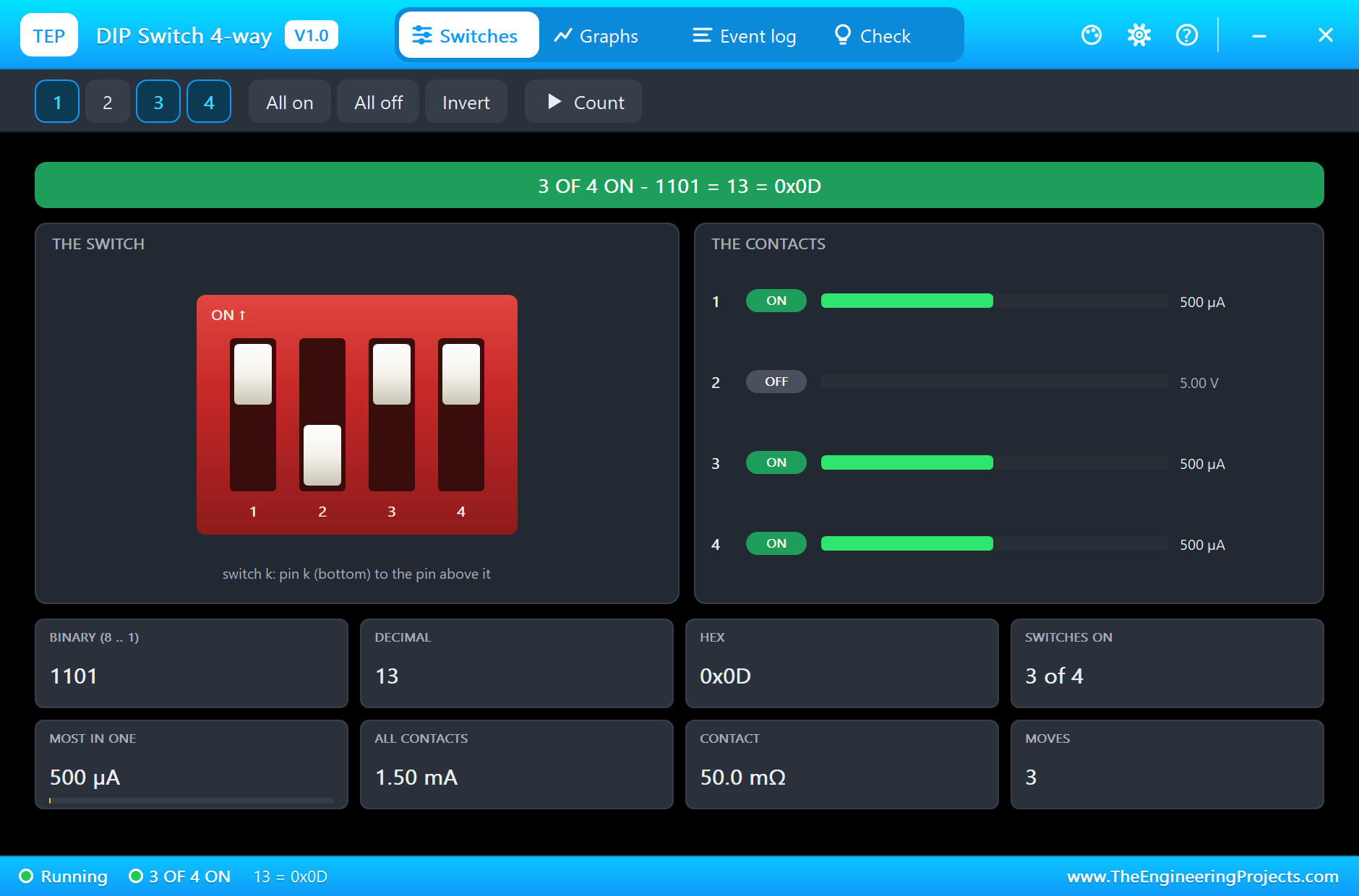
A DIP switch is a row of tiny switches in a chip-sized case, set once with the tip of a pen and then left alone: the right part for settings that an installer chooses on site. Each switch is one bit. The program reads switches 1 and 2 as a two-bit number, switch 1 worth 1 and switch 2 worth 2, so they give 0 to 3 and pick one of four walk times: 0 = 6 s, 1 = 8 s, 2 = 10 s and 3 = 12 s. Switch 3 turns the ticks on and switch 4 the red-and-amber step. In the run below, switches 1, 3 and 4 are on: the code is 1 + 2 x 0 = 1, an 8 second walk, with the ticks and the red-and-amber step. The program reads the switches all the time and prints each change, and every crossing uses the settings of the moment it starts.
Pull-Down Resistors
A GPIO input that is connected to nothing floats: it picks up noise and reads 0 or 1 at random. A switch to 3.3 V only drives the pin while it is closed, so something must pull the pin to 0 when it is open: a resistor to ground, a pull-down. With the switch open, the 10 kohm resistor holds the pin at 0 V; with it closed, the pin sits at 3.3 V and the resistor takes only 3.3 / 10000 = 0.33 mA. The Raspberry Pi also has pull-ups and pull-downs built into its GPIO pins, but they are weak, of the order of 50 kohm; a 10 kohm resistor on the board holds the input five times harder against noise, which matters for a button on a long cable in a crossing post. The slide switch needs no pull-down at all, because its common pin always touches GND or 3.3 V.
Reading a Bouncing Button
The contacts of a push button bounce for a few milliseconds when they close, so one press can look like many. The program watches the button every 20 ms; when it sees the input go high, it waits 30 ms and reads it again, and only a press that is still there counts. A short spike of noise is ignored, and one press makes one request.
Lighting the LEDs
A red SMD LED drops about 2.0 V, so on a real Pi's 3.3 V pin the 220 ohm resistor gives (3.3 - 2.0) / 220 = 5.9 mA: plenty for an indicator, and the six lamps together stay far below what the Pi's GPIO can supply. The program sets the five signal lamps together with one small function, so the cars and the people can never be shown green at the same time by mistake: every state is one call, such as red for the cars and the green man for the people.
Three Threads
The program does three things at once, each in its own thread. The inputs thread reads the button, the DIP switch and the slide switch every 20 ms. The controller thread runs the sequence: it waits in CARS GREEN or flashes the night amber, and when a request is due it runs one whole crossing. The main thread serves the web pages. They share one small dictionary of state, the request, the crossings, the night flag and the settings, and a lock makes sure that no thread reads it half-written. A press on the button and a press of REQUEST on the dashboard call the same function, so the crossing cannot tell them apart.
The Python Code Explained
The whole program is included in the download. It needs no extra library: lgpio for the GPIO, threading and http.server for the dashboard. At the top are the pins, the times and the walk times:
CAR_R, CAR_A, CAR_G, PED_R, PED_G, WAIT, BUZZER = 17, 27, 22, 23, 24, 25, 18 # BCM numbersBUTTON, DIP, NIGHT_SW = 5, [6, 13, 19, 26], 12MIN_GREEN, AMBER, ALL_RED, CLEAR, RED_AMBER = 20.0, 3.0, 1.0, 4.0, 2.0 # seconds
WALK_TIMES = [6.0, 8.0, 10.0, 12.0] # DIP 1 and 2The inputs are claimed as plain inputs, because the resistors on the board do the pulling:
lgpio.gpio_claim_input(chip, g) # (the 10k pull-downs on the board hold the inputs LOW; the slide switch drives its own)The Settings from the DIP Switch
The four switches become the walk time, the ticks and the red-and-amber step in one line:
return d, WALK_TIMES[d[0] + 2 * d[1]], bool(d[2]), bool(d[3])A Request
Only the first request lights WAIT; any more presses are only counted:
first = s['request'] is None and s['state'] in ('CARS GREEN', 'NIGHT')The button counts only if it is still pressed 30 ms after the rising edge:
        if b and not last_btn:
            time.sleep(0.03)
            if lgpio.gpio_read(chip, BUTTON):
                request('the button')
The Crossing
The controller starts a crossing when there is a request and the cars have had their minimum green:
if req is not None and time.monotonic() - green_since >= MIN_GREEN:The green man with the fast ticks, then the flashing green man, silent:
hold(walk, (0.04, 0.2) if ticks else None) # fast ticks: cross now lights('R', 'G'); time.sleep(0.25); lights('R', ''); time.sleep(0.25)Then, if DIP 4 is on, red and amber before the cars' green:
lights('RA', 'R'); event('cars RED and AMBER'); hold(RED_AMBER)The Night
At night, with no request waiting, the controller flashes the cars' amber once a second:
lights('A', 'R'); time.sleep(0.5); lights('', 'R'); time.sleep(0.5)The pages are / (the dashboard), /request (a crossing request, as the button) and /data (everything as JSON). The dashboard puts its links first and stays short, because the WiFi Monitors show one screen of a page. The Pi's terminal prints every event with its time.
How to Run the Proteus Simulation
- Download the project zip below and install the library files and the TEPPi folder (the steps are under the download button).
- Open Pi-5-Pedestrian-Crossing.pdsprj from the Proteus Simulation folder. Keep pedestrian_crossing.py and the DLL files next to it.
- Press Play. The cars have green and the red man shows.
- Press PUSH TO CROSS (its cap, or Press on its pop-up): WAIT lights, and after the cars' minimum green the crossing runs.
- Click the DIP switch or the slide switch to change the walk time, the ticks, the red-and-amber step or DAY and NIGHT.
- Open the Laptop or the Mobile WiFi Monitor and press Go for the dashboard, with REQUEST.
Simulation Results: the Pedestrian Crossing in Proteus
Here is the run that made the screenshots of this tutorial: a crossing by day, the night mode and a crossing at night, 69.6 seconds of simulation. The times below are the program's own clock, as it printed them on the Pi's terminal; the parts' numbers come from their pop-ups.
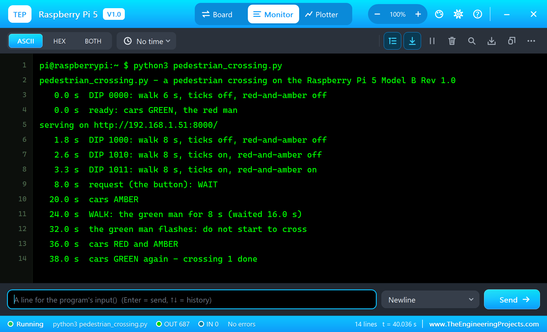
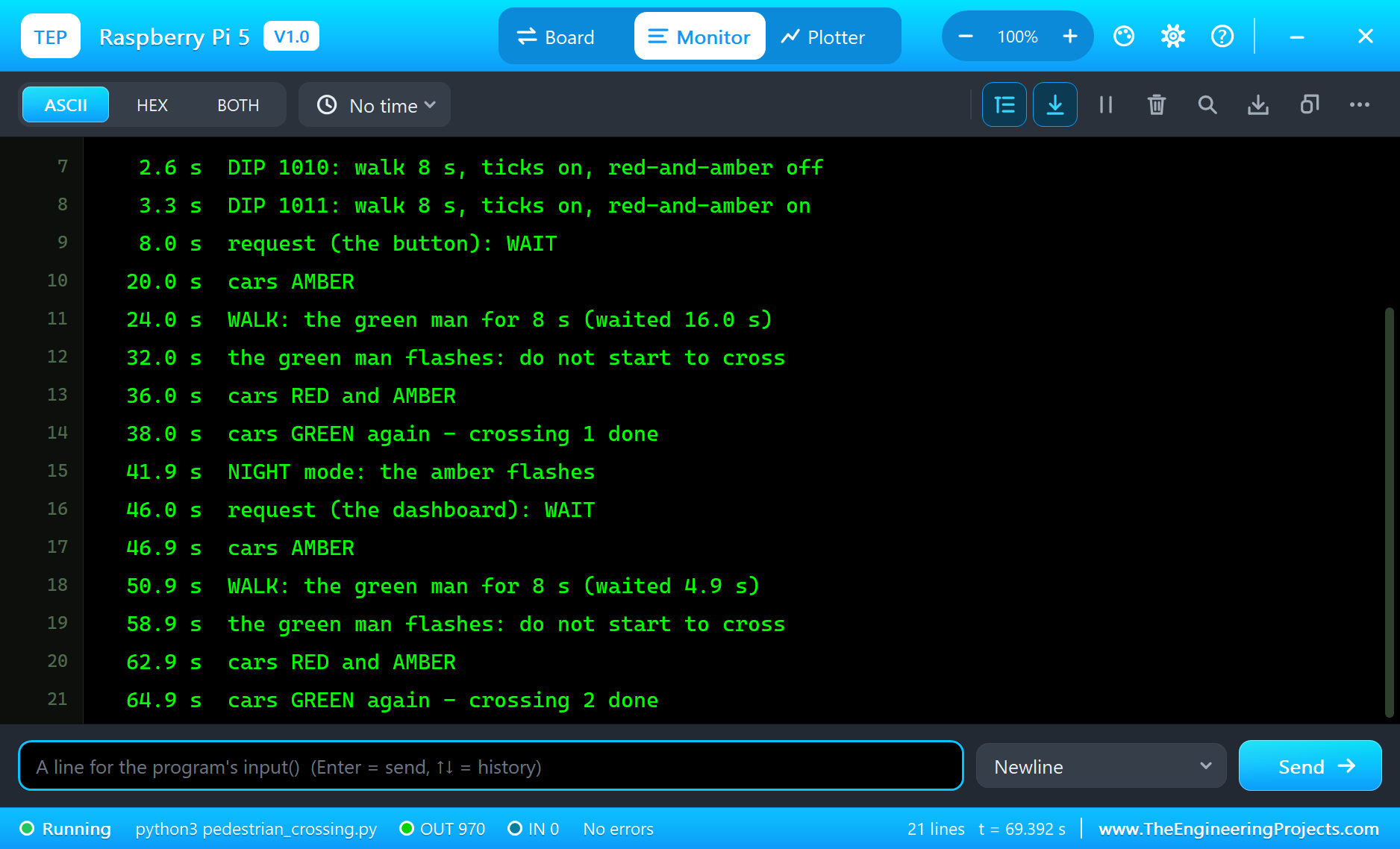
The Settings: DIP 1011
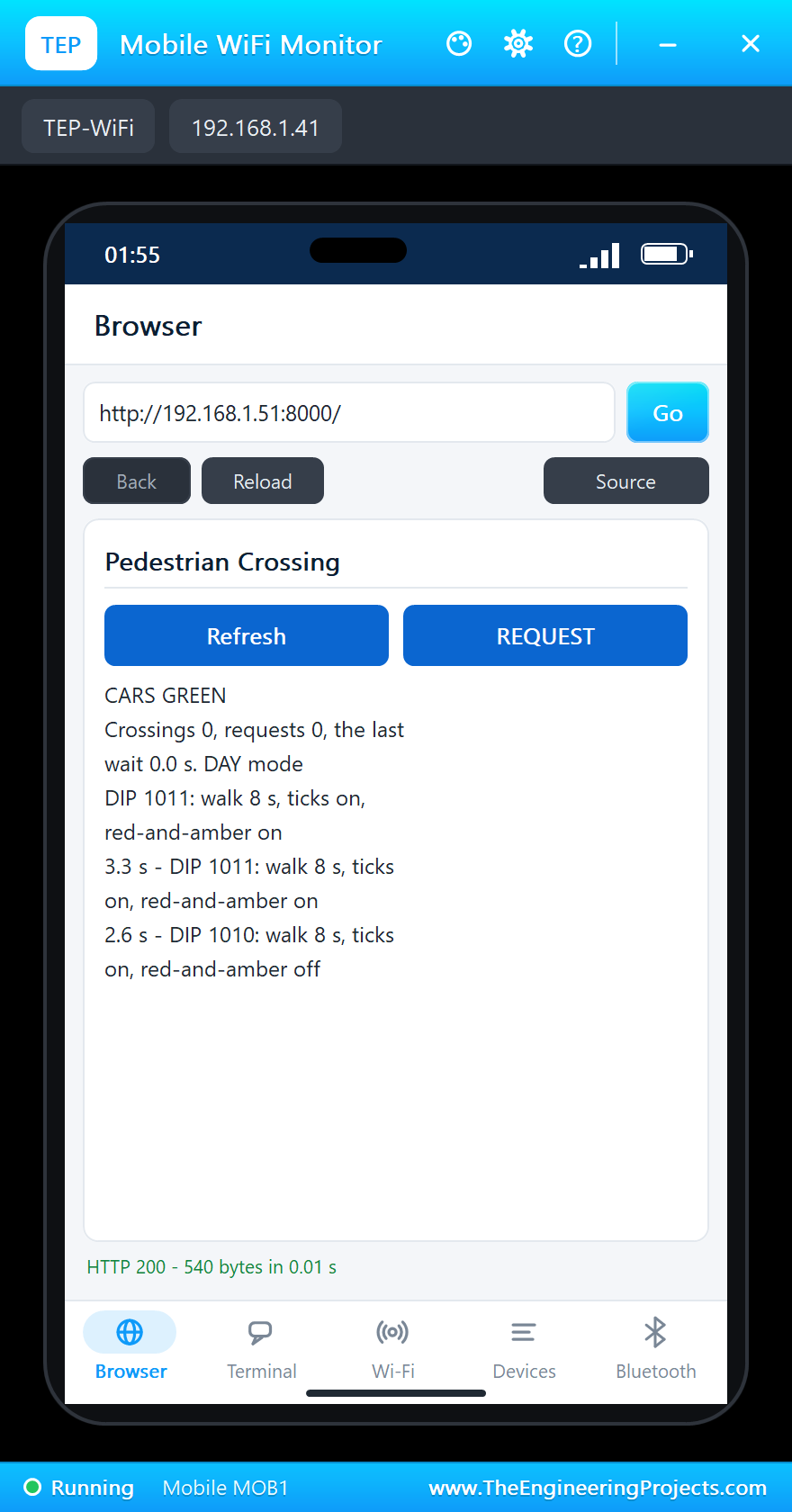
The program starts with the DIP switch all off: "DIP 0000: walk 6 s, ticks off, red-and-amber off". Switches 1, 3 and 4 are then turned on from the DIP switch's pop-up, and the program reports each change: at 3.3 s "DIP 1011: walk 8 s, ticks on, red-and-amber on". The pop-up shows the same switches from its own side, written the other way round as a binary number, 1101 = 13 = 0x0D, with 500 uA through each closed contact into its 10 kohm pull-down. The phone's dashboard shows the cars green, no crossings yet and the settings.
PUSH TO CROSS: WAIT and the Minimum Green
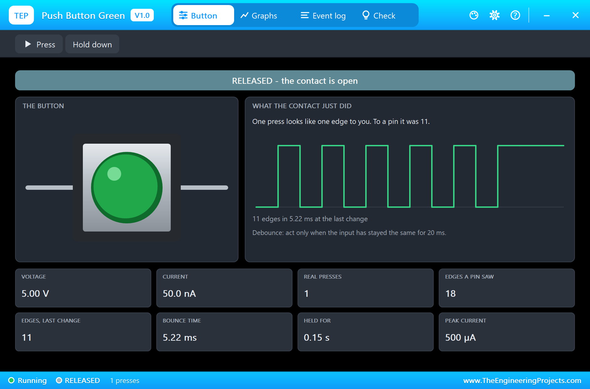
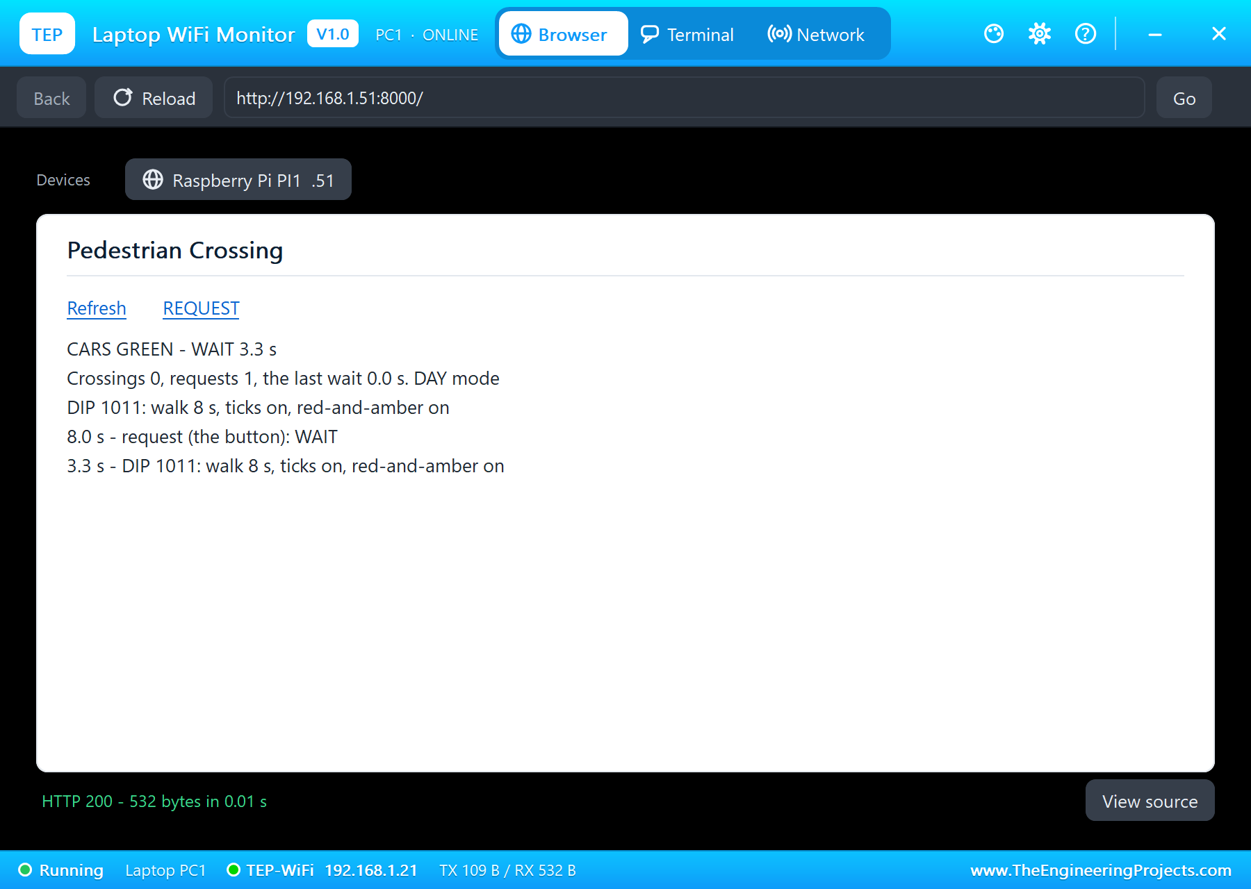
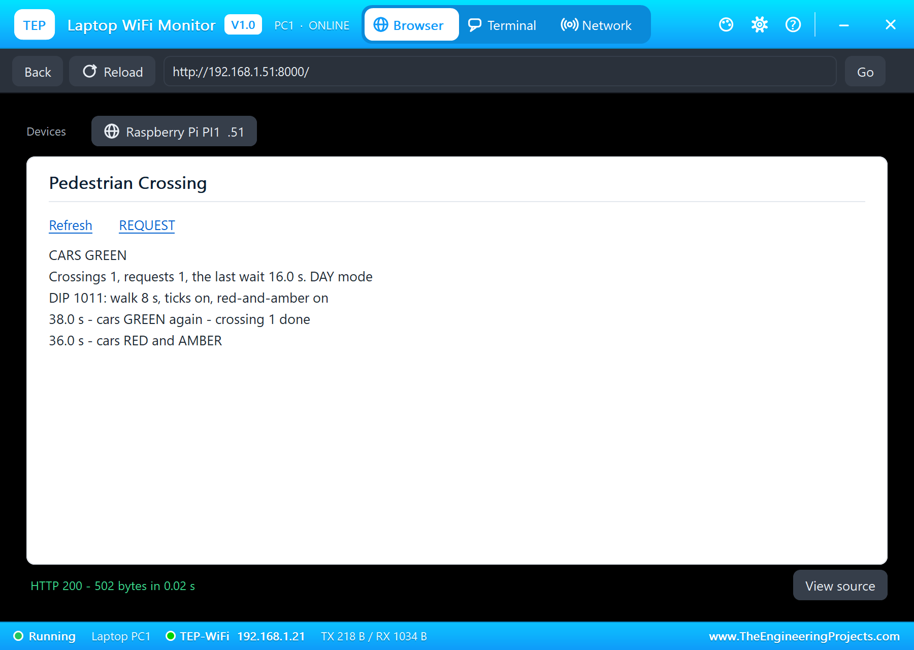
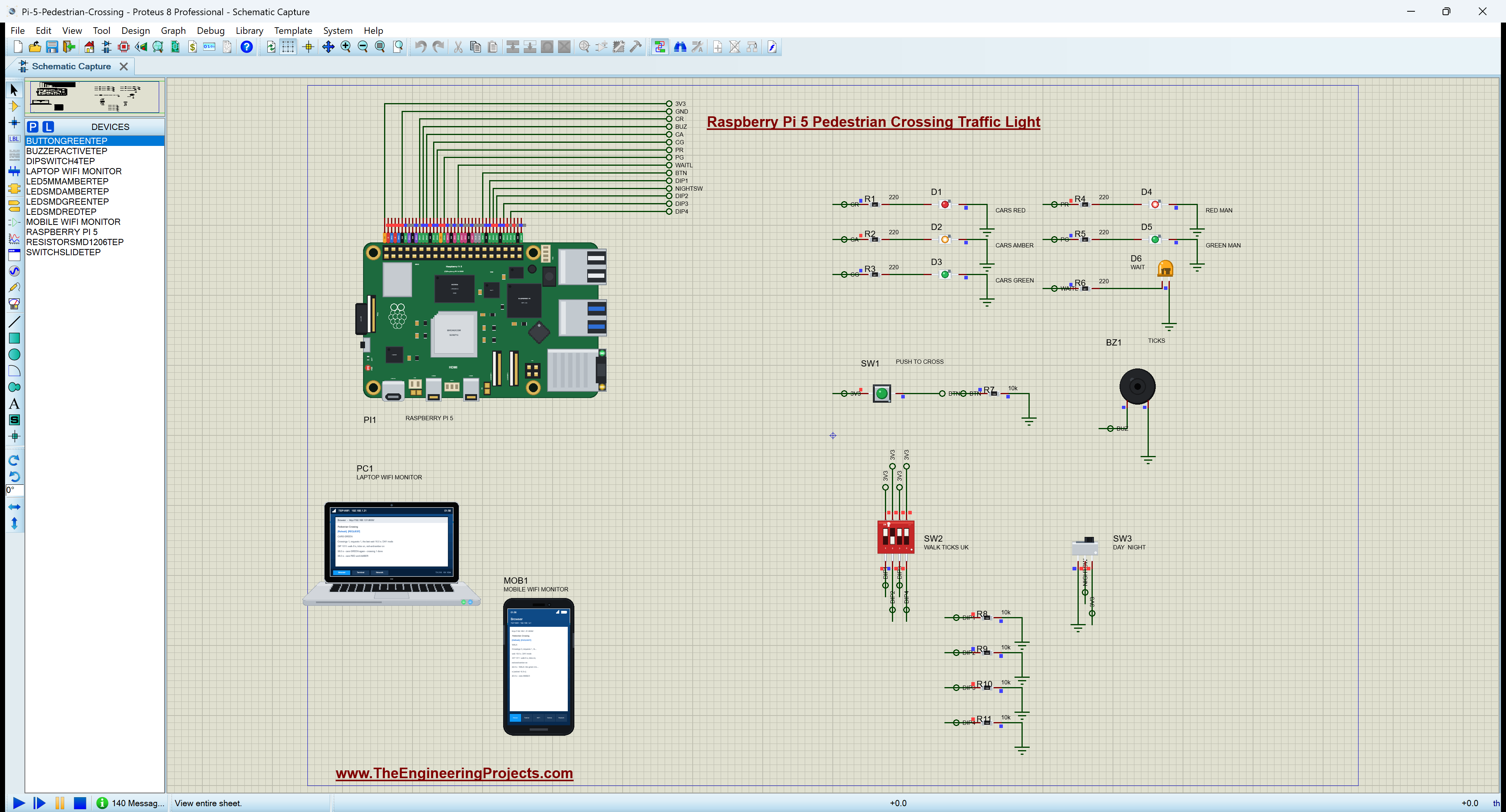
At 8.0 s PUSH TO CROSS is pressed: "request (the button): WAIT". The button's pop-up shows one real press with 11 bounce edges in 5.22 ms, held for 0.15 s; the program's 30 ms check saw it as one request. On the sheet the WAIT lamp is lit, but the cars still have green and the people the red man: the cars have had only 8 of their 20 seconds of minimum green. The laptop's dashboard counts the wait: "CARS GREEN - WAIT 3.3 s".
Amber, All Red and WALK
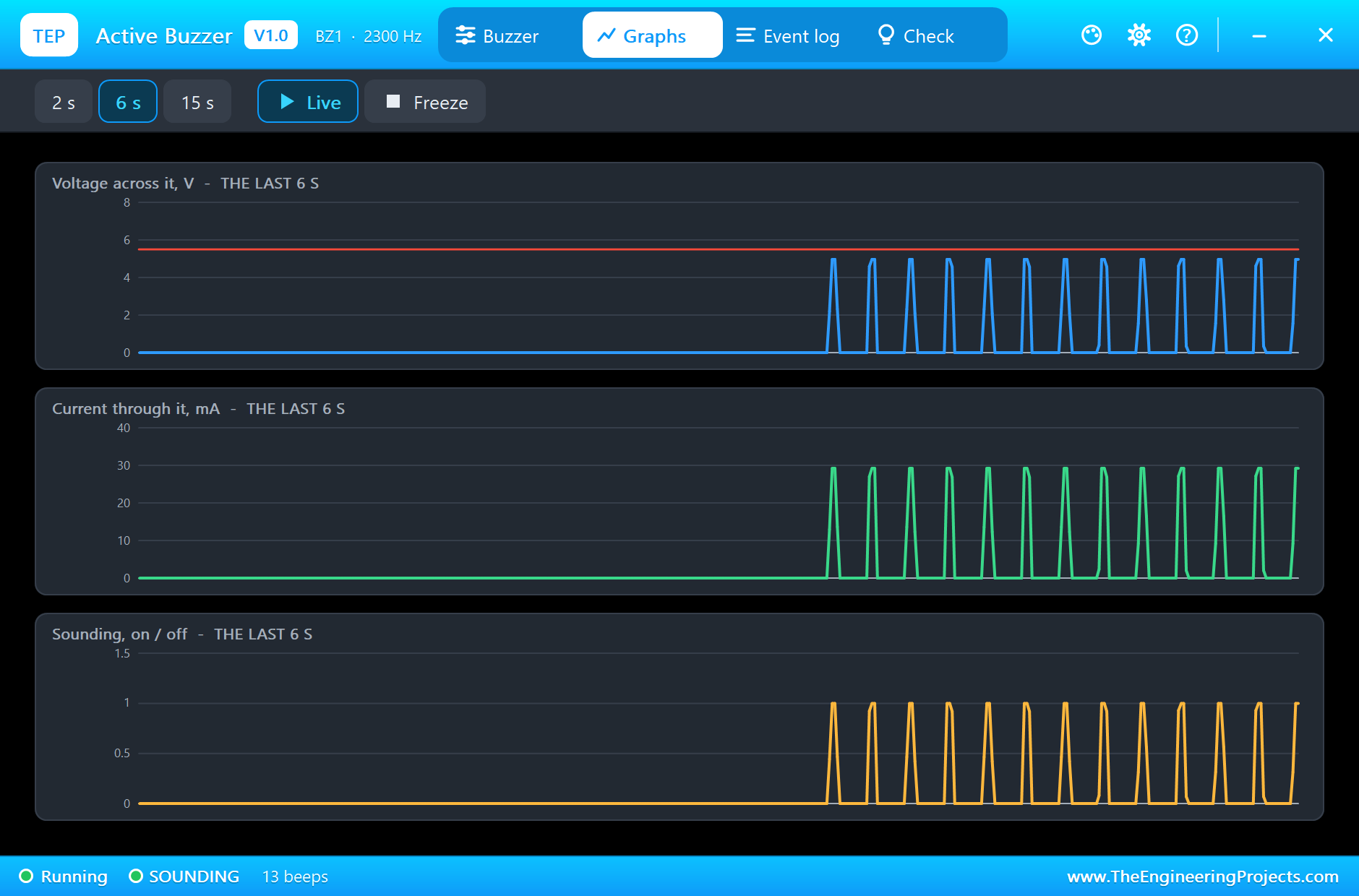
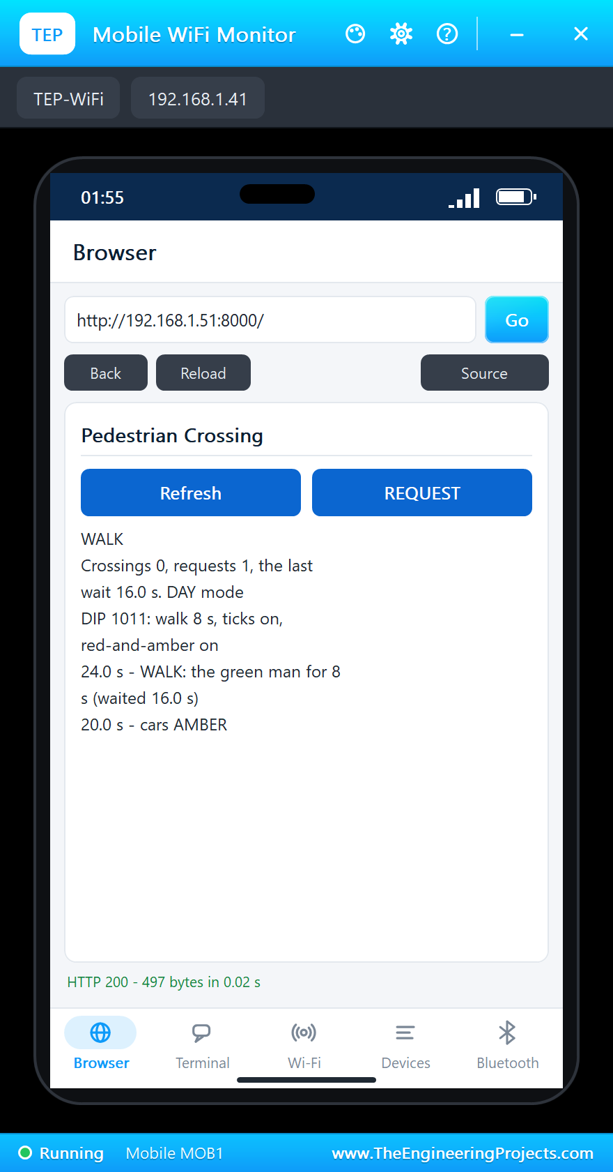
At 20.0 s, exactly when the minimum green runs out, "cars AMBER": the cars' amber lamp and still the red man. Three seconds of amber and one of all red later, at 24.0 s, "WALK: the green man for 8 s (waited 16.0 s)": the cars red, the green man lit and the WAIT lamp off. The buzzer ticks five times a second, 2300 Hz, and its pop-up's graphs show every tick. The phone's dashboard says WALK.
Clearance, Red and Amber, Green
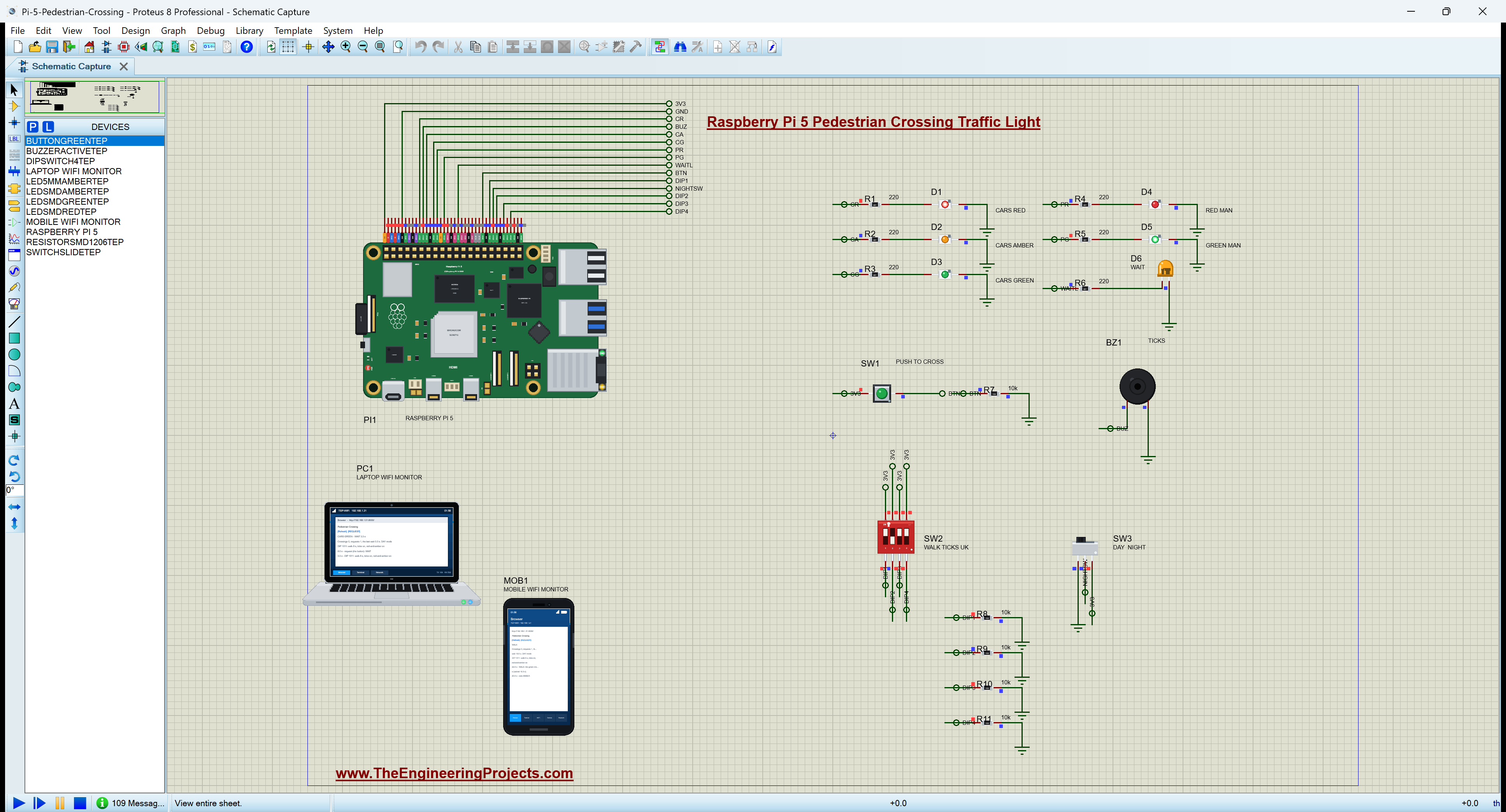
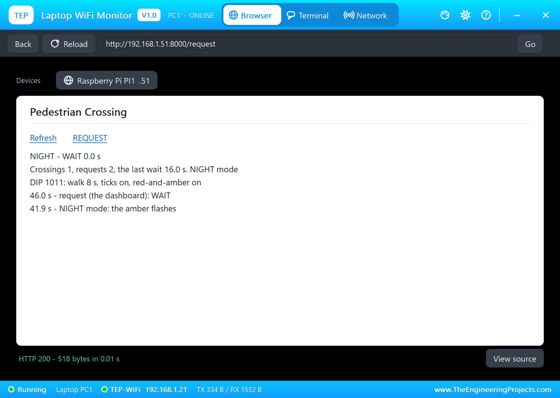
At 32.0 s "the green man flashes: do not start to cross": it flashes twice a second and the buzzer goes quiet. At 36.0 s the red man again and "cars RED and AMBER", and at 38.0 s "cars GREEN again - crossing 1 done". The laptop's dashboard now reads one crossing, one request and the last wait 16.0 s.
NIGHT and a Crossing from the Laptop
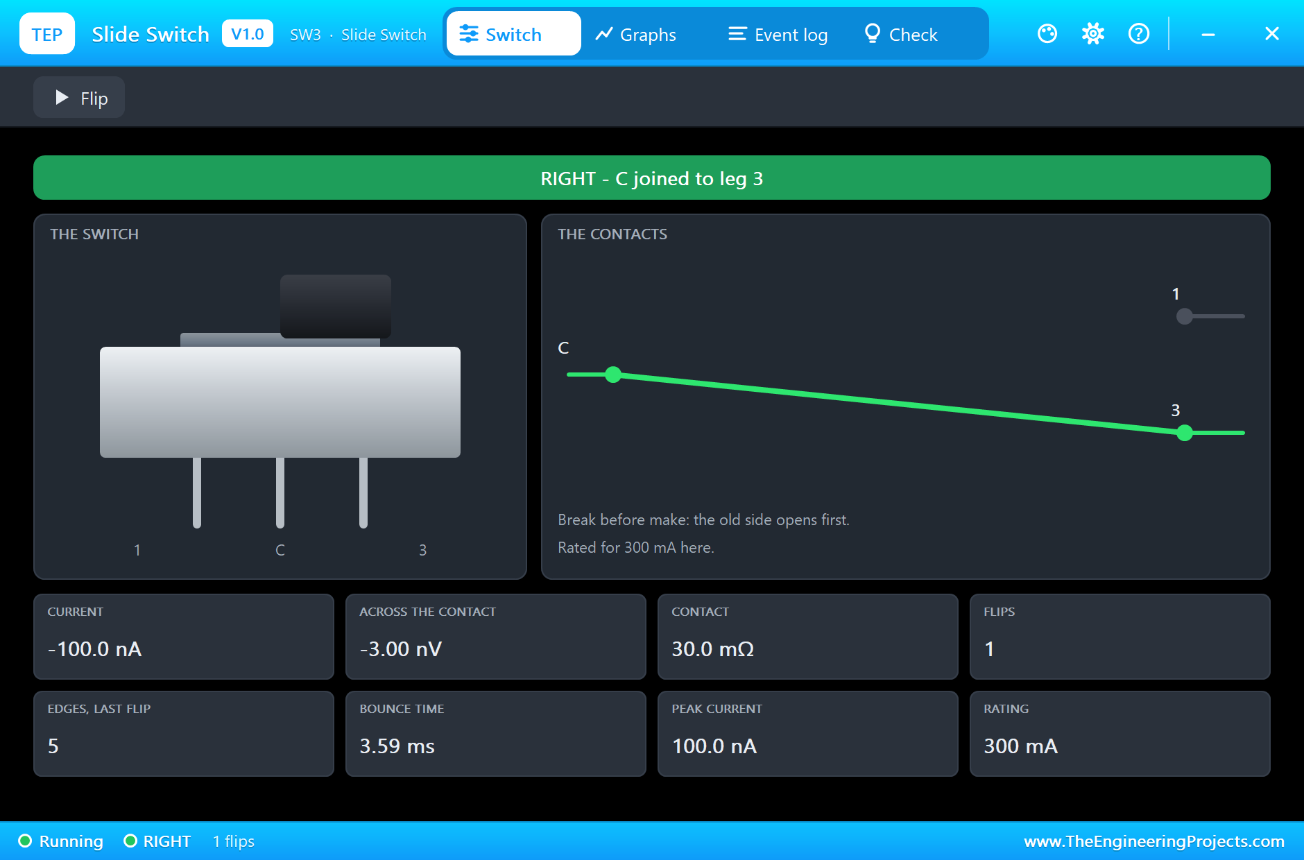
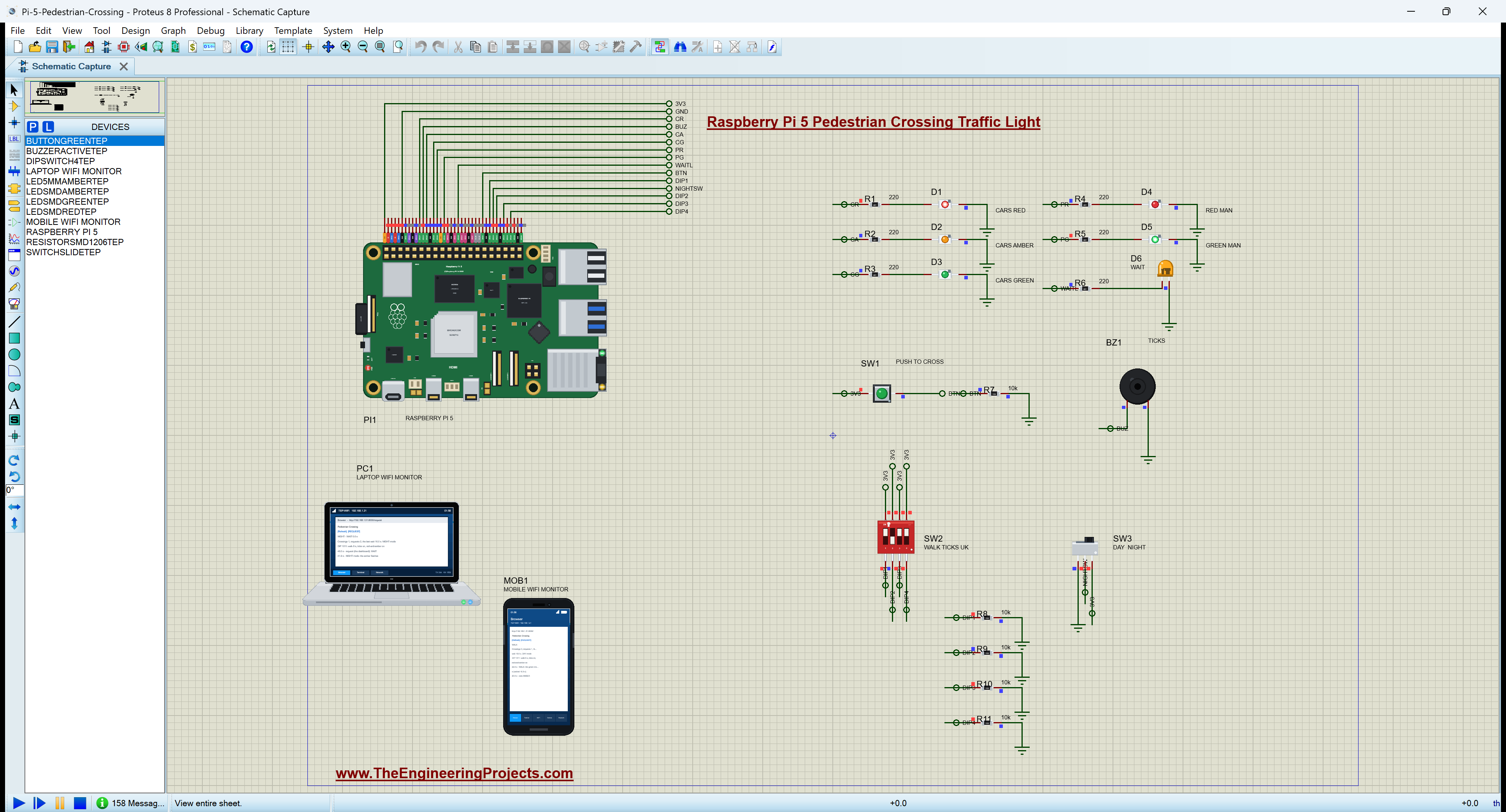
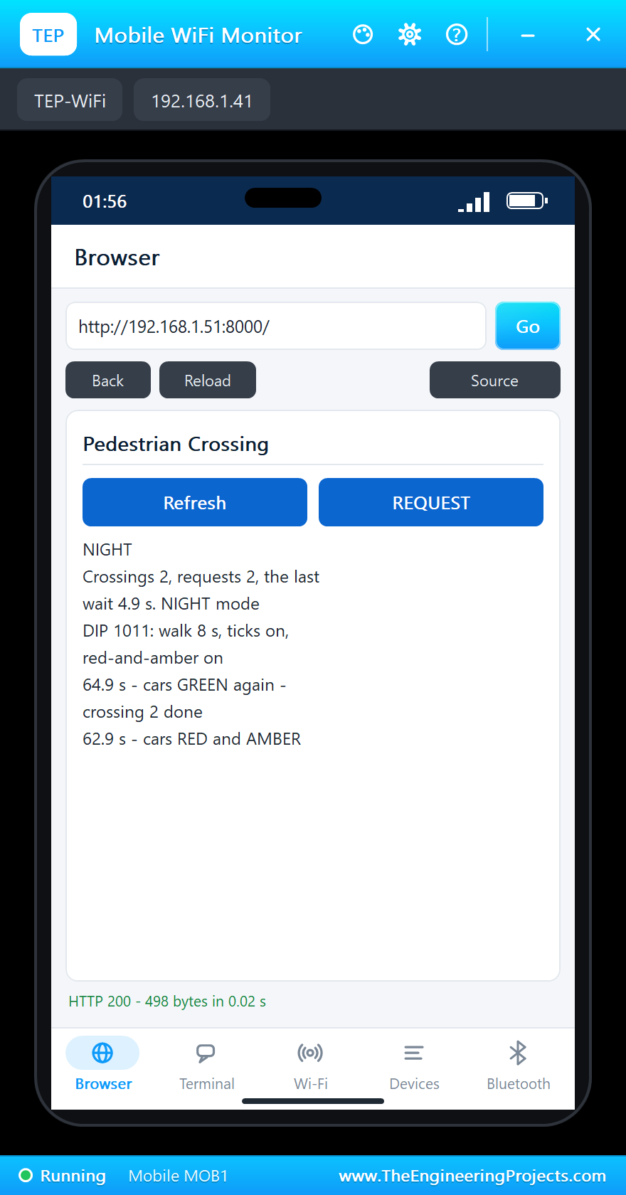
At 41.9 s the slide switch goes to NIGHT; its pop-up shows C joined to leg 3, the 3.3 V side, and the program reports "NIGHT mode: the amber flashes". The cars' amber now flashes once a second. At 46.0 s REQUEST is pressed on the laptop: "request (the dashboard): WAIT". At night the cars are not held to a minimum green, so the crossing starts at the end of the flash, at 46.9 s, and at 50.9 s "WALK: the green man for 8 s (waited 4.9 s)". The rest of the crossing runs as by day, and at 64.9 s "crossing 2 done": the crossing goes back to flashing amber, and the phone shows NIGHT, two crossings and two requests.
The models agree with the program: the buzzer counted 80 ticks, five a second through two 8-second walks, and the lamps drew about 14 mA each through their 220 ohm resistors from the simulated Pi's pins (a real Pi's 3.3 V pins give about 6 mA, as worked out above).
The Numbers of the Run
| What | Result |
|---|---|
| DIP switch | 1011: walk 8 s, ticks on, red-and-amber on (the pop-up: 1101 = 13) |
| The button | one press, 11 bounce edges in 5.22 ms, seen as one request |
| Crossing 1 (day) | pressed at 8.0 s, amber at 20.0 s (the minimum green), WALK at 24.0 s: waited 16.0 s |
| The sequence | amber 3 s, all red 1 s, WALK 8 s with ticks, clearance 4 s, red and amber 2 s |
| NIGHT | at 41.9 s: the amber flashing once a second |
| Crossing 2 (night, from the laptop) | requested at 46.0 s, WALK at 50.9 s: waited 4.9 s |
| The ticks | 80 in all, five a second during the green man |
| Simulation | 69.6 s of simulation, two crossings |
Download the Project Files
Click the button below to download Raspberry-Pi-5-Pedestrian-Crossing-Traffic-Light-Proteus-Simulation-v1.0.zip (about 14.8 MB, without the source code of the models):
Raspberry Pi 5 Pedestrian Crossing Traffic Light in Proteus Simulation V1.0- Proteus Simulation: Pi-5-Pedestrian-Crossing.pdsprj, the program pedestrian_crossing.py and copies of the models.
- Python Code: pedestrian_crossing.py, the complete program.
- Proteus Library Files: the LIB files of the Raspberry Pi 5, the SMD LEDs, the 5 mm LED, the DIP switch, the slide switch, the SMD resistors, the push button, the active buzzer and the two WiFi Monitors.
- Proteus Model Files: the DLL models and the TEPPi folder, the Python 3.11 and the runtime that the Pi board runs.
- README.txt: the installation steps, the properties, the test results and the links to every library post.
No Proteus yet? Read How to Download and Install Proteus 7 and 8. New to libraries? Follow How to Install a New Library in Proteus.
How to Install the Project Files
- Close Proteus and extract the whole zip file, for example to your Desktop.
- Copy the files from Proteus Library Files into the LIBRARY folder of Proteus.
- Copy everything in Proteus Model Files, the DLL files and the TEPPi folder, into the MODELS folder.
- Start Proteus and open the project from the Proteus Simulation folder.
Changing the Code
The program is plain Python 3: edit pedestrian_crossing.py beside the project and press Play again; the Pi board runs the new file. The timings, the walk times and the pins are at the top. The same program runs on a real Raspberry Pi 5 with Raspberry Pi OS and lgpio. For our other Pi 5 project for the road, which finds free spaces in a car park, see the Raspberry Pi 5 Smart Parking System.
Ideas to Extend the Project
- Add a countdown display that shows the seconds left of the green man.
- Detect people still on the road with a radar or an infrared sensor and stretch the clearance, as modern crossings do.
- Count the cars with a sensor and give a longer green when the traffic is heavy.
- Join two crossings on one road and time them so the cars meet green at both.
- Log every request and crossing to a file and plot the busy hours.
- Add a vibrating button or a turning cone for deafblind people.
From Simulation to Real Hardware
- Never drive real signal lamps from the Pi: street signals run from mains power; they need relays or solid-state switches and a proper controller.
- Real controllers check themselves: a road controller watches the lamp currents and goes to a safe state if a red lamp fails; this project is a teaching model.
- Use resistors on every LED: 220 ohm on a 3.3 V pin is safe for indicator LEDs.
- Long wires to the button: a button on a long cable picks up noise; keep the 10 kohm pull-down close to the Pi and add a small capacitor.
- Keep the timings to the rules: real crossings follow national standards for every time in the sequence.
Troubleshooting
- A lamp never lights: its LED is the wrong way round (A to the resistor, K to GND) or the GPIO is wrong.
- The button does nothing: it must switch 3.3 V to GPIO5, with R7 from GPIO5 to GND.
- The walk time is wrong: check DIP 1 and 2: 00 = 6 s, 10 = 8 s, 01 = 10 s, 11 = 12 s (switch 1 first).
- NIGHT never comes: the slide switch's C must go to GPIO12, leg 3 to 3.3 V.
- The terminal cannot start Python: the TEPPi folder is not in the MODELS folder.
Limitations of the Simulation
- The simulated Pi's GPIO pins drive full 5 V logic levels, so the LED currents in the simulation are higher than a real Pi's 3.3 V pins would give.
- The times in this tutorial are the program's own clock; the simulation runs slower than real time, and the program follows the simulated time.
- The network is simulated: the dashboard travels between the Pi and the two monitors inside Proteus.
- Raspberry Pi is a trademark of Raspberry Pi Ltd. This project is not made or endorsed by them or by Labcenter, and it is a teaching model, not a road traffic controller.
So, that was all about the Raspberry Pi 5 Pedestrian Crossing Traffic Light (Proteus Simulation), the fiftieth project of the series. I hope it helps you understand why a crossing has every step of its sequence, how the walk and the clearance times come from the width of a road, how to read a DIP switch as a number through pull-down resistors, how to debounce a button, and how threads and a state machine keep a real device responsive, all tested in a simulation before you build anything. More IoT projects with the ESP32 and the Raspberry Pi 5 are coming. If you have any questions, ask in the comments and I will help you out. Till the next tutorial, take care and have fun!

Comments
0