


nRF5340 DK Library for Proteus: Dual-Core Bluetooth LE Simulation


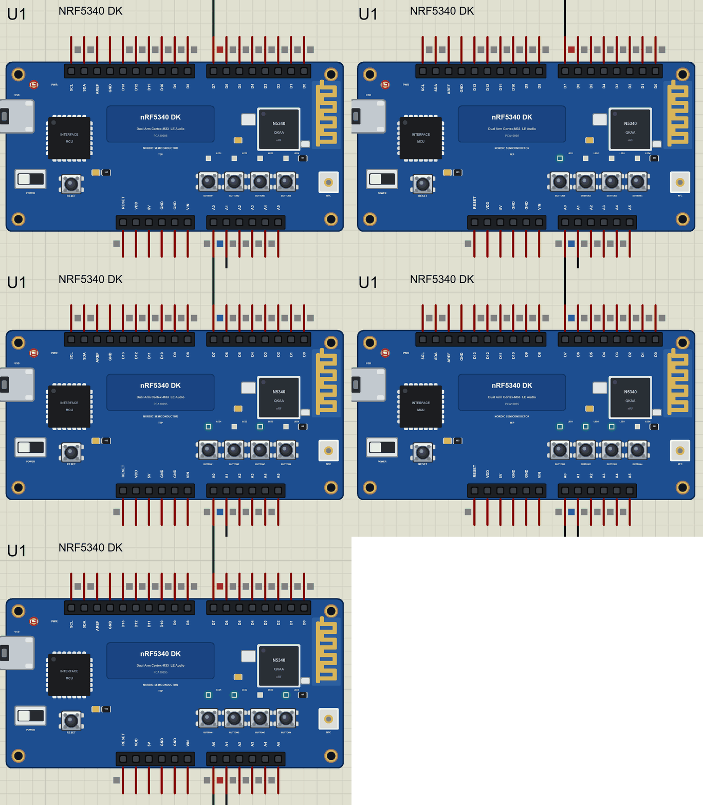
Hello friends, I hope you all are doing great. Today, I am going to share the nRF5340 DK Library for Proteus, so you can run a Bluetooth LE simulation of Nordic Semiconductor's dual-core development kit. The nRF5340 is the chip Nordic built for the newest Bluetooth features, such as LE Audio, and its DK is the board many research groups and product teams start with. With this library it runs your Arduino sketch in Proteus 8.5, its four LEDs light up, its four buttons work with a click, and a phone on the sheet connects to it over Bluetooth LE.
nRF5340 DK Library for Proteus
Latest version: V1.0 (November 2026, this tutorial)
Helping Tools
- Laptop WiFi Monitor: a laptop on the Wi-Fi of your design: a browser, a TCP / UDP terminal and ping
- Mobile WiFi Monitor: a smartphone that opens the pages of your board and sends it commands
- Serial Monitor Advance: a serial terminal window for the UART of your board
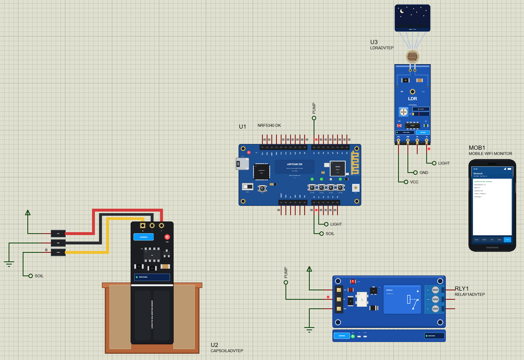
For the demo we built a Bluetooth LE plant monitor. A capacitive soil moisture sensor and an LDR light module watch a pot plant, a relay switches the water pump, and the phone reads the soil and the light, waters the plant and sets the dry limit. The four LEDs and the four buttons each have a job, so the whole kit takes part in the simulation.
NOTICE: Proteus has no nRF5340 model, so our team has put a lot of effort into building this board ourselves: the DK's Arduino header, the LEDs, the buttons and the Bluetooth LE link are all our own model, and your sketch compiles with our free TEP Boards for Proteus add-on. Your feedback is the fuel that keeps us going, so please tell us what you think in the comments below. And if our free libraries help you, you can buy us a coffee. So, let's get started with the nRF5340 DK Library for Proteus:
What is the nRF5340 DK?
The nRF5340 DK (its board number is PCA10095) is Nordic Semiconductor's development kit for the nRF5340 system-on-chip. It shares its shape with the older nRF52840 DK: a blue board with the chip and its printed antenna at one end, an on-board debugger with its own USB port at the other, and the familiar Arduino Uno header in between. Four LEDs and four buttons sit next to the chip, and a power switch, an NFC antenna connector and extra flash memory complete the kit.
| Feature | The real nRF5340 DK | In the library |
|---|---|---|
| Chip | nRF5340: two Arm Cortex-M33 cores | your Arduino sketch, as one program |
| Application core | up to 128 MHz, 1 MB flash, 512 KB RAM | about 256 KB of flash, 8 KB of RAM |
| Network core | 64 MHz, 256 KB flash, 64 KB RAM, runs the radio | part of our Bluetooth LE link |
| Radio | Bluetooth LE with LE Audio, Thread, Zigbee, NFC | Bluetooth LE to the phone |
| On the board | four LEDs, four buttons, RESET, power switch | all of them, animated |
| Header | Arduino Uno Rev3 layout, 3.3 V logic | the same pins and labels |
Two Cores in One Chip
The nRF5340 is the first Nordic chip with two processors. The application core is a fast Arm Cortex-M33 for your program, with plenty of flash and RAM. The network core is a second, smaller Cortex-M33 that looks after the radio and the Bluetooth controller. Splitting the work this way means the radio's strict timing never interrupts your code, and your code never disturbs the radio. In Nordic's nRF Connect SDK the network core runs a ready-made controller image, so most developers simply write the application and let the second core do its job.
Why LE Audio Matters
Classic Bluetooth audio has served headphones for twenty years, but it was never designed for low power or for sharing. LE Audio moves sound onto Bluetooth Low Energy with a new codec, LC3, that gives good quality at a low bit rate. It also brings Auracast broadcast audio, so one transmitter can serve any number of listeners, as in an airport or a lecture hall. Hearing aids, earbuds and conference systems are moving to it, and the nRF5340 is one of the chips that made it practical. Our plant monitor uses the same Bluetooth LE basics, advertising, services and characteristics, without the audio part.
Bluetooth Low Energy in a Nutshell
A device such as our plant monitor is a peripheral: it sends short advertising packets that say its name and what it offers. A phone is the central: it scans, picks a device and connects. Once connected, the peripheral offers services, and each service holds characteristics, small values with a UUID that can be read, written, or set to notify, which pushes every new value to the phone without being asked. If you have read our nRF52840 DK Library for Proteus, this will feel familiar: the two kits share the same header, the same LEDs and buttons and the same Bluetooth model.
Features of the nRF5340 DK Library for Proteus
- The board as it looks: the blue DK with its headers, the nRF5340 and its meander antenna, the interface MCU and USB port, the power switch, RESET, four LEDs and four buttons, drawn compact, with our small TEP signature.
- Your sketch: a .hex for "Nordic nRF5340 DK (TEP Proteus)" with the DK's pin names: D0 to D13, A0 to A5, SDA, SCL, LED1 to LED4 and BUTTON1 to BUTTON4.
- Real LEDs and buttons: the LEDs glow on the board in the running simulation and light when LOW, as on the real DK; the buttons are clicked on the board and read LOW while you hold them.
- Bluetooth LE: ArduinoBLE services and characteristics with read, write and notify; the Bluetooth app of our Mobile WiFi Monitor is the central.
- A built-in serial monitor: click the USB port, with the Monitor, Plotter and Board tabs.
- A complete package: about 4.5 MB with the part, the add-on, the soil sensor, LDR, relay and phone libraries and the demo, without the source code of the models.
The nRF5340 DK in Proteus Simulation
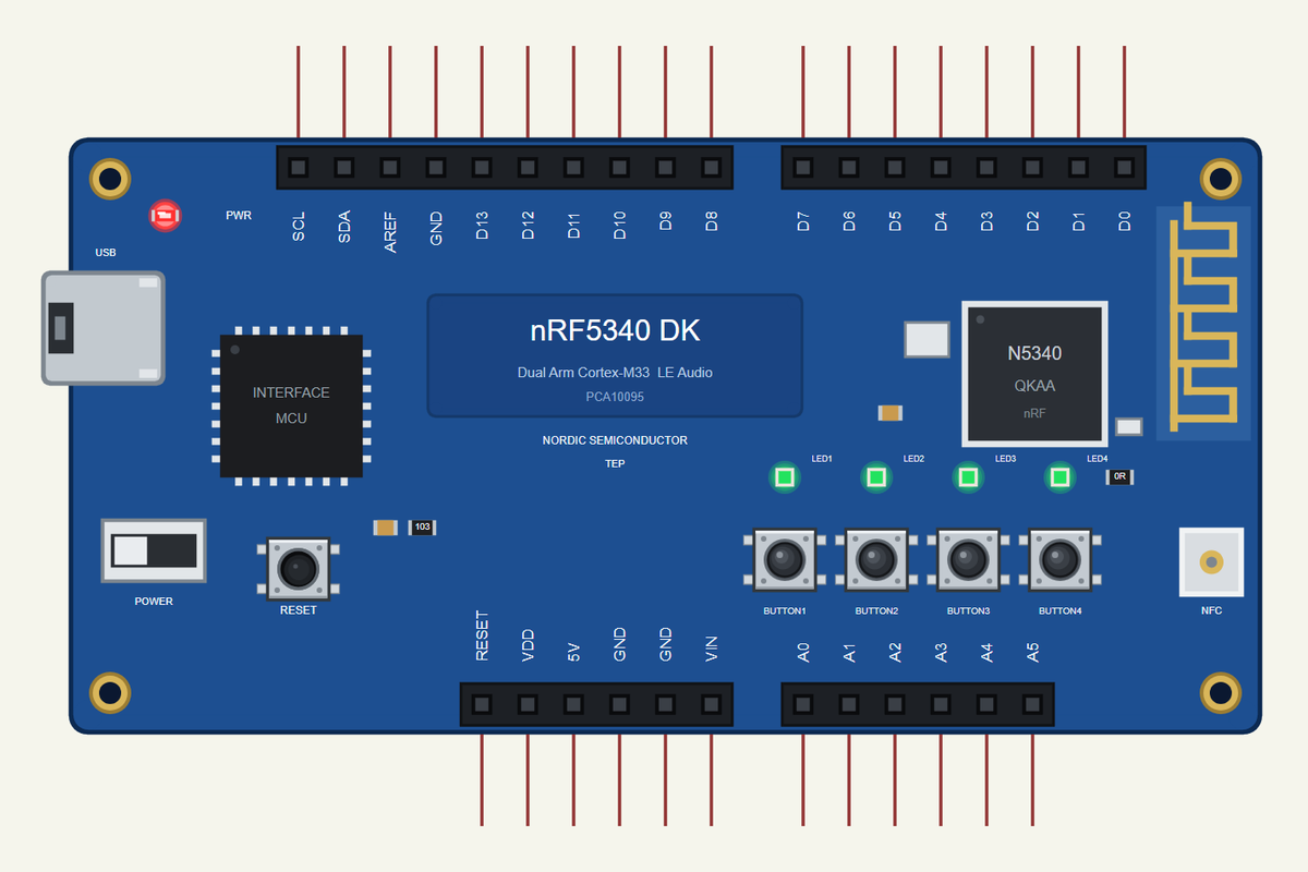
Search NRF5340 in Pick Devices; the device is in TEPNRF5340DK.LIB (Microprocessor ICs, Bluetooth Boards), with the prefix U. Click the USB port for the serial monitor. The headers follow the real silk, so a pin you read on the real board has the same name in the simulation.
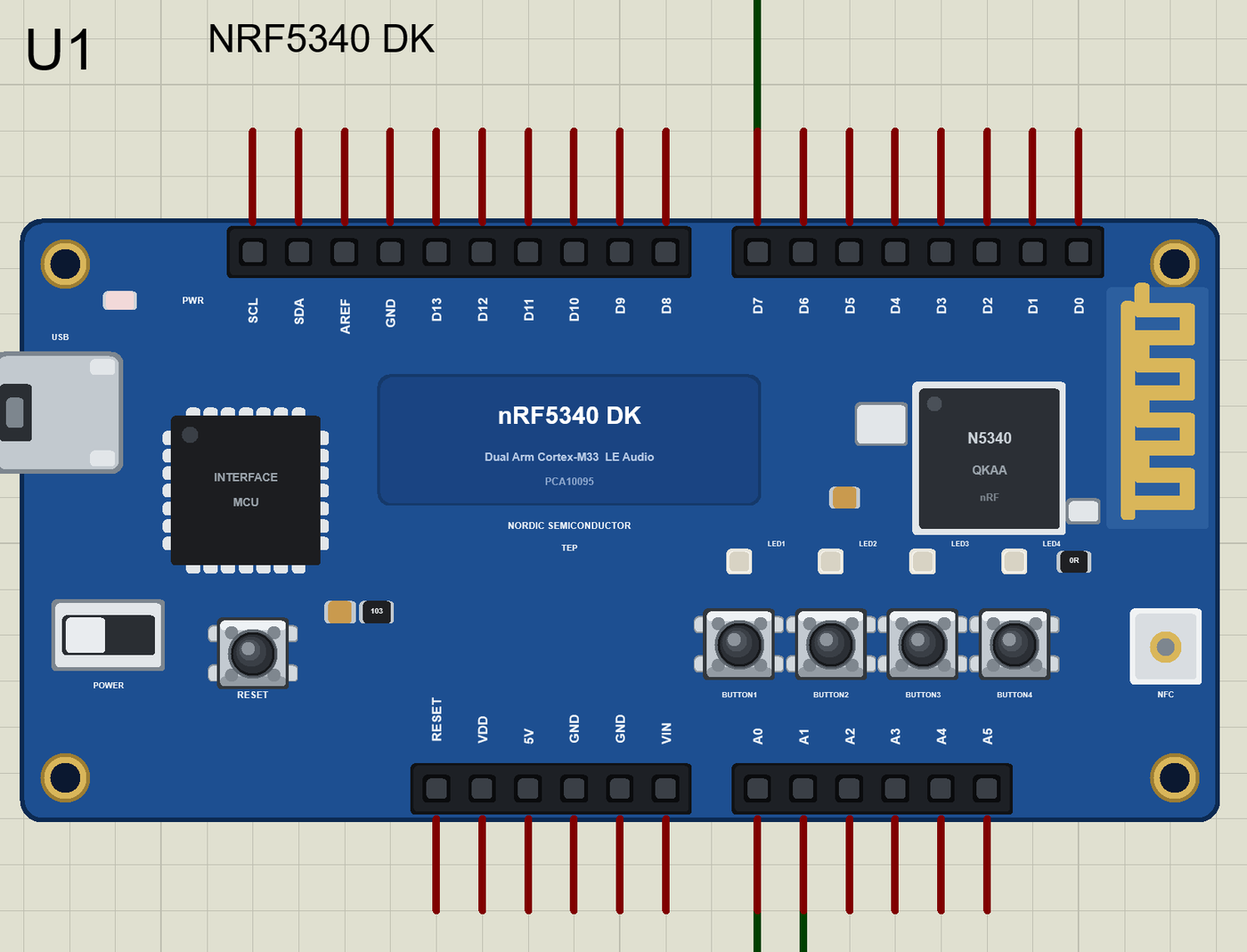
The Pins
| Pins | What the library does with them |
|---|---|
| D0, D1 | Serial1 RX and TX, or GPIO |
| D2 to D13 | GPIO, PWM with analogWrite, attachInterrupt |
| D10 to D13 | SPI: SS, MOSI, MISO, SCK |
| A0 to A5 | analogRead 0 to 1023 for 0 to 3.3 V, or GPIO |
| SDA, SCL | Wire, the I2C bus |
| VDD, 5V, GND, RESET | the supply and the reset |
| AREF, VIN | drawn, not modelled |
The LEDs and the Buttons
LED1 to LED4 are the green LEDs, and they light when the pin is LOW, exactly as on the real DK, where they sit on P0.28 to P0.31. LED_BUILTIN is LED1. BUTTON1 to BUTTON4 are the four push buttons, which the real board wires to P0.23, P0.24, P0.08 and P0.09. Use pinMode(BUTTON1, INPUT_PULLUP), and a button reads LOW while you hold it down with the mouse in the simulation. The add-on's pins_arduino.h lists the real P0 or P1 pin of every header pin.
Download nRF5340 DK Library for Proteus
Click the button below to download nRF5340-DK-Library-for-Proteus-v1.0.zip (about 4.5 MB, without the source code of the models):
nRF5340 DK Library for Proteus V1.0- README.txt: installation, the demo, the pins, the properties, troubleshooting and the limits.
- Proteus Library Files:
TEPNRF5340DK.LIBand the demo's parts:TEPCAPSOIL.LIB,TEPLDR.LIB,TEPRELAY.LIB,TEPMOBILE.LIBandTEPLAPTOP.LIB. - Proteus Model Files:
TEPNET.DLL,TEPCAPSOIL.DLL,TEPLDR.DLLandTEPRELAY.DLL. - Arduino Code: the demo sketch and the TEP Boards for Proteus add-on 1.60.0, with ArduinoBLE.
- Proteus Simulation: the demo project, its HEX file and copies of the DLLs.
No Proteus yet? Read How to Download and Install Proteus 7 and 8. New to libraries? Follow How to Install a New Library in Proteus.
How to Install nRF5340 DK Library for Proteus
- Close Proteus and extract the whole zip file, for example to your Desktop.
- Copy the files from Proteus Library Files into the LIBRARY folder of Proteus.
- Copy the DLLs from Proteus Model Files into the MODELS folder, replacing an older TEPNET.DLL.
- Delete
TEPNRF5340DK.IDXfrom the LIBRARY folder if it is there. - For your own sketches, copy Arduino Code\TEP Boards for Proteus\hardware into your Arduino sketchbook (Documents\Arduino) and restart the Arduino IDE; the board is Nordic nRF5340 DK (TEP Proteus). ArduinoBLE comes with the add-on, and the demo needs no other library.
- Start Proteus, press P and search for NRF5340.
Demo: a Bluetooth LE Plant Monitor in Simulation
A pot plant is a good first wireless project, because it asks only a few things: water when the soil is dry, light during the day, and someone who checks on it. Our monitor does the checking, waters the plant by itself, and tells the phone everything. It uses every one of the DK's LEDs and buttons, so you can see the whole board at work.
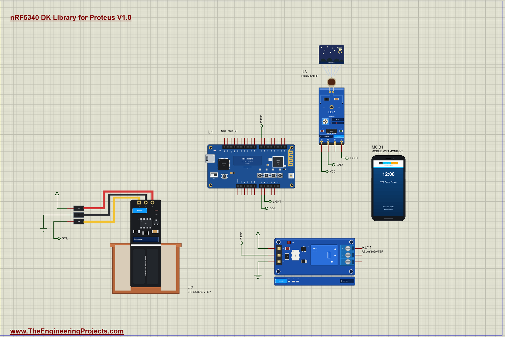
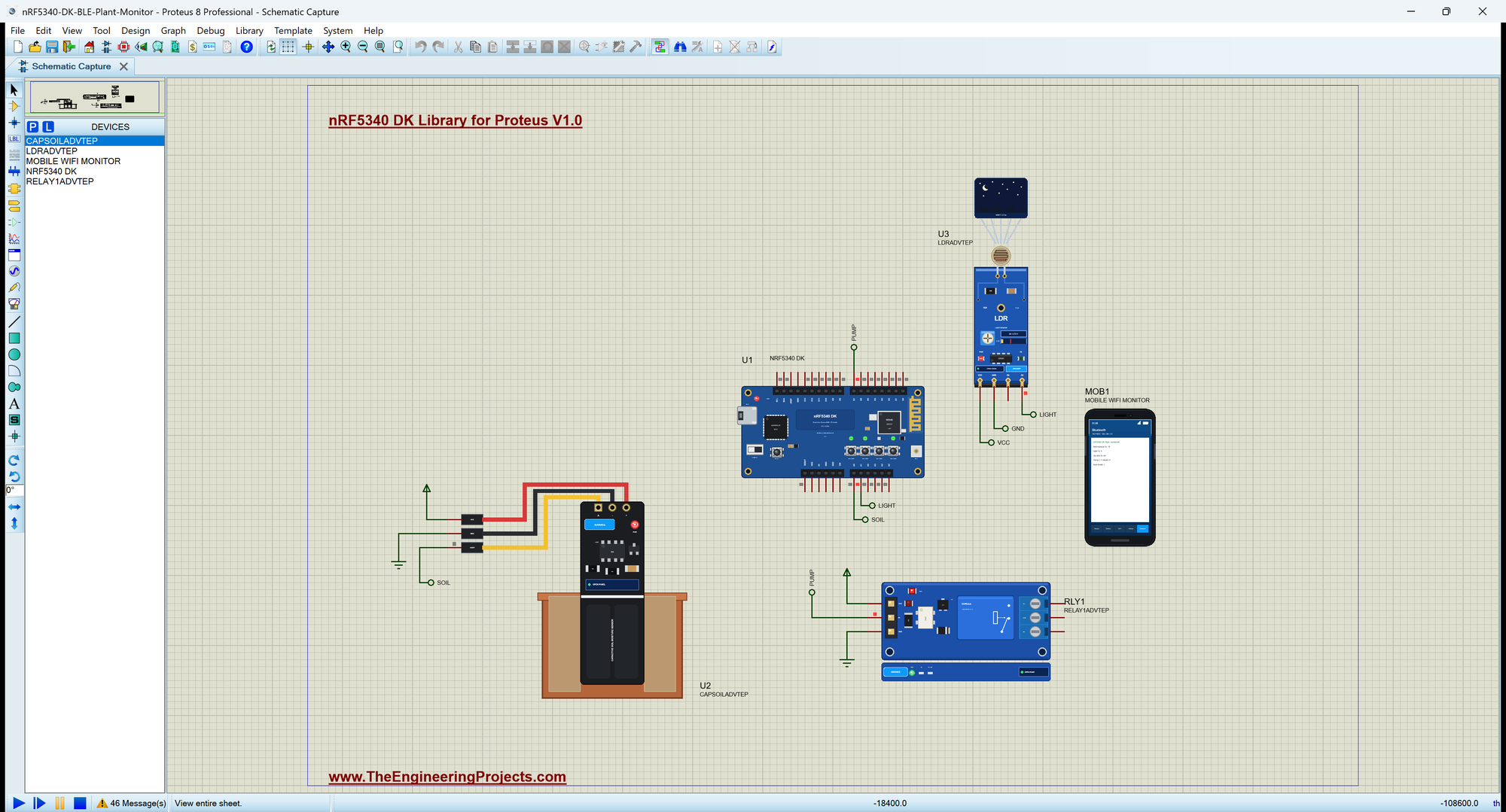
Open nRF5340-DK-BLE-Plant-Monitor.pdsprj. U1 runs DK_BLE_Plant_Monitor.hex. U2 comes from our Capacitive Soil Moisture Sensor Library, U3 from our LDR Sensor Library and RLY1 from our Relay Module Library, all three in the Advance version. MOB1 is the phone, with no wires. The monitor is the same window as our TEP Serial Monitor Advance for Proteus.
The Wiring
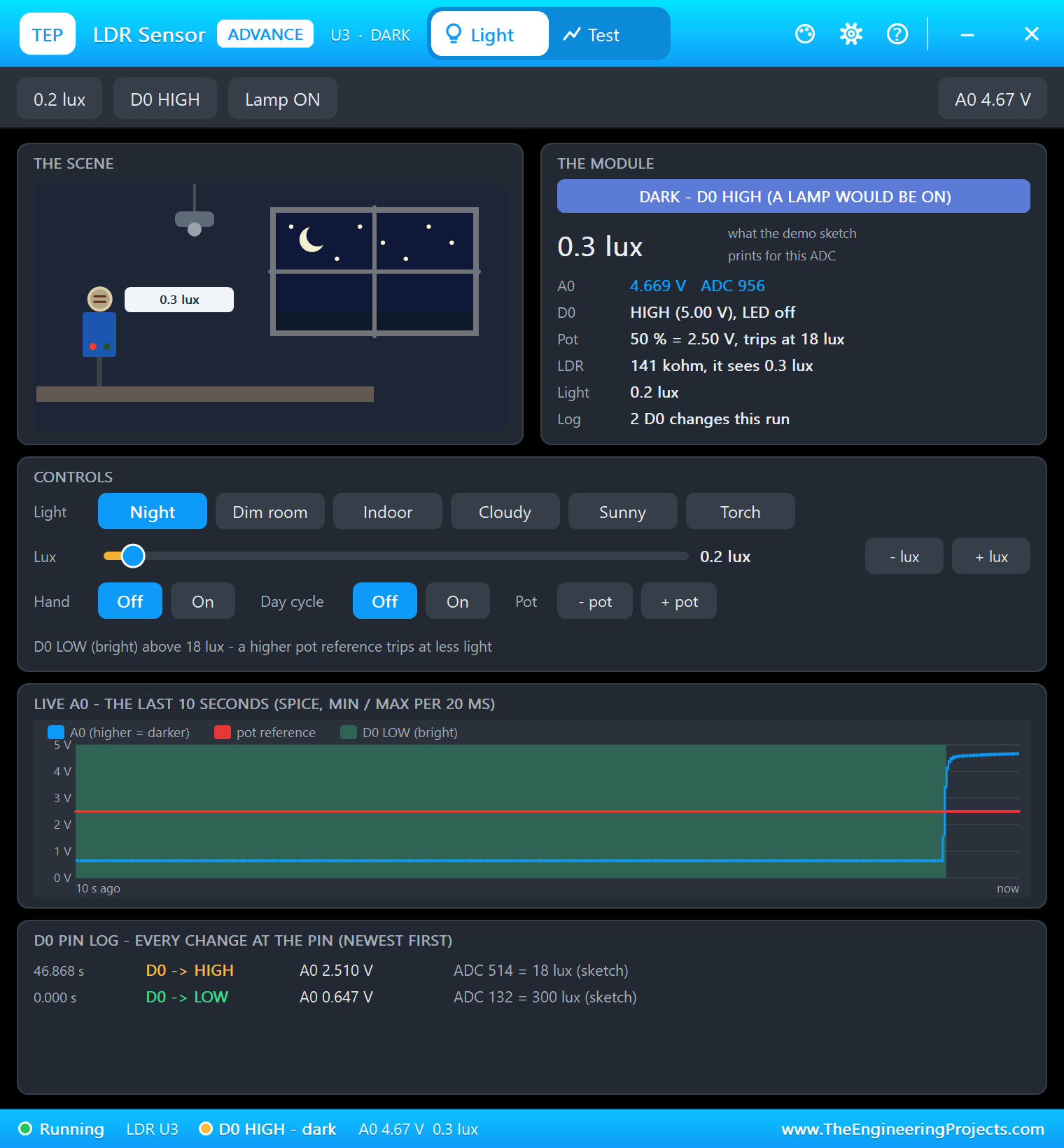
The capacitive soil sensor's AOUT goes to A0 through the label SOIL. A capacitive sensor gives a higher voltage in dry soil and a lower one in wet soil, and it never corrodes, because no metal touches the earth. The LDR module's analog output A0 goes to the DK's A1 through the label LIGHT; its voltage rises as the room gets darker. The relay's IN is on D7 through the label PUMP. This relay module switches on when its input is LOW, so the sketch writes HIGH to the pin before it makes it an output, and the pump never twitches at power-up.
The Bluetooth Services
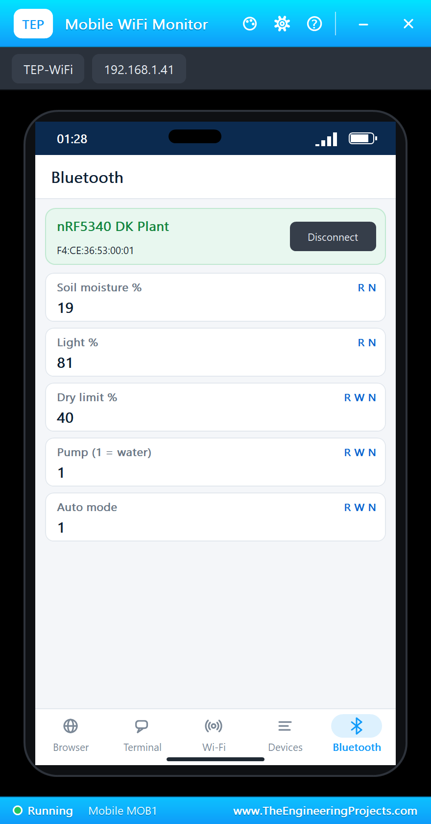
Soil moisture has no standard Bluetooth characteristic, so the monitor uses one custom service with 128-bit UUIDs. Every value is a single byte, which keeps the packets tiny:
| Characteristic | Access | What it holds |
|---|---|---|
| Soil moisture % | read, notify | 0 (air) to 100 (water) |
| Light % | read, notify | 0 (dark) to 100 (bright) |
| Dry limit % | read, write, notify | below this the soil counts as dry |
| Pump (1 = water) | read, write, notify | the pump; the phone can start it |
| Auto mode | read, write, notify | 1 = water by itself, 0 = by hand only |
BLEService plantService("19B10020-E8F2-537E-4F6C-D104768A1214");
BLEByteCharacteristic soilChar("19B10021-E8F2-537E-4F6C-D104768A1214", BLERead | BLENotify);
BLEByteCharacteristic lightChar("19B10022-E8F2-537E-4F6C-D104768A1214", BLERead | BLENotify);
BLEByteCharacteristic limitChar("19B10023-E8F2-537E-4F6C-D104768A1214", BLERead | BLEWrite | BLENotify);
BLEByteCharacteristic pumpChar("19B10024-E8F2-537E-4F6C-D104768A1214", BLERead | BLEWrite | BLENotify);
BLEByteCharacteristic autoChar("19B10025-E8F2-537E-4F6C-D104768A1214", BLERead | BLEWrite | BLENotify);
BLEDescriptor soilLabel("2901", "Soil moisture %");
BLEDescriptor lightLabel("2901", "Light %");
BLEDescriptor limitLabel("2901", "Dry limit %");
BLEDescriptor pumpLabel("2901", "Pump (1 = water)");
BLEDescriptor autoLabel("2901", "Auto mode");
Reading the Plant
Once a second readPlant() turns the two analog readings into percentages. The soil sensor is calibrated with two numbers, its reading in air and in water, and everything in between becomes 0 to 100 %. The light is the LDR's reading turned upside down. LED2 shows dry soil and LED4 a dark room, and in auto mode dry soil starts the pump:
void readPlant() {
  const long raw = analogRead(SOIL_PIN);
  soil = constrain((SOIL_DRY - raw) * 100 / (SOIL_DRY - SOIL_WET), 0, 100);
  light = 100 - (long)analogRead(LIGHT_PIN) * 100 / 1023;   // the LDR module's output rises in the dark
  soilChar.writeValue(soil);
  lightChar.writeValue(light);
  const bool dry = soil < dryLimit;
  led(1, dry);
  led(3, light < 20);
  Serial.print(F("Soil ")); Serial.print(soil);
  Serial.print(F(" %  light ")); Serial.print(light);
  Serial.print(F(" %  limit ")); Serial.print(dryLimit);
  Serial.print(F(" %  pump ")); Serial.print(pump ? F("ON") : F("OFF"));
  Serial.println(autoMode ? F("  auto") : F("  manual"));
  if (autoMode && dry && !pump && millis() >= restUntil) setPump(true, F("the soil is dry"));
}
The Pump
setPump() is the only place that touches the relay. It also lights LED3, tells the phone, and remembers two times: when the watering ends, and when the pump may run again. The rest time matters in a real garden, because water needs a while to soak in, and a sensor that still reads dry would otherwise flood the pot:
void setPump(bool on, const __FlashStringHelper *why) {
  if (on == pump) return;
  pump = on;
  digitalWrite(PUMP_PIN, on ? LOW : HIGH);                  // the relay module switches on when its IN is LOW
  led(2, on);
  pumpChar.writeValue(on);
  if (on) { pumpUntil = millis() + WATER_MS; restUntil = pumpUntil + REST_MS; }
  Serial.print(F(">> Pump "));
  Serial.print(on ? F("ON (") : F("OFF ("));
  Serial.print(why);
  Serial.println(F(")"));
}
Four Buttons, Four Jobs
The sketch remembers the last state of every button and acts only on the moment of the press. BUTTON1 waters, BUTTON2 and BUTTON3 move the dry limit by 5 %, and BUTTON4 switches between auto and manual:
void handleButtons() {
  for (byte k = 0; k < 4; k++) {
    const bool now = digitalRead(BUTTONS[k]);
    if (now == lastButton[k]) continue;
    lastButton[k] = now;
    if (now != LOW) continue;                               // act on the press
    Serial.print(F(">> BUTTON"));
    Serial.println(k + 1);
    if (k == 0) setPump(true, F("BUTTON1"));
    else if (k == 1) setLimit(dryLimit - 5, F("   BUTTON2"));
    else if (k == 2) setLimit(dryLimit + 5, F("   BUTTON3"));
    else setAuto(!autoMode, F("   BUTTON4"));
  }
}
The Phone and LED1
handlePhone() watches the connection and the three writable characteristics. While nobody is connected, LED1 blinks every 400 ms; when the phone connects it stays on. A write from the phone goes through the same functions as a button, so the two can never disagree:
void handlePhone() {
  const bool now = BLE.connected();
  if (now != wasConnected) {
    wasConnected = now;
    if (now) {
      BLEDevice central = BLE.central();
      Serial.print(F(">> Phone connected: "));
      Serial.println(central.address());
      led(0, true);
    } else Serial.println(F(">> Phone left - advertising again"));
  }
  if (limitChar.written()) setLimit(limitChar.value(), F(">> Phone"));
  if (pumpChar.written()) setPump(pumpChar.value() != 0, F("the phone"));
  if (autoChar.written()) setAuto(autoChar.value() != 0, F(">> Phone"));
  if (!now && millis() >= nextBlink) {                      // LED1 blinks while the node advertises
    nextBlink = millis() + BLINK_MS;
    blinkOn = !blinkOn;
    led(0, blinkOn);
  }
}
Run the Simulation
Press Run. The monitor opens and prints the banner, the address and the button help. LED1 blinks, because the node is advertising, and a status line follows every second. After five seconds the sketch prints the raw sensor readings once, which is how you calibrate your own soil sensor:
nRF5340 DK Bluetooth Plant Monitor - The Engineering Projects
Advertising as "nRF5340 DK Plant", address F4:CE:36:53:00:01
BUTTON1 = water now, BUTTON2 / 3 = dry limit -/+ 5 %, BUTTON4 = auto mode
Soil 100 %  light 81 %  limit 30 %  pump OFF  auto
Soil 94 %  light 81 %  limit 30 %  pump OFF  auto
Soil 81 %  light 81 %  limit 30 %  pump OFF  auto
Soil 78 %  light 81 %  limit 30 %  pump OFF  auto
Soil 78 %  light 81 %  limit 30 %  pump OFF  auto
Sensors: soil raw 479 (air 790, water 395), light raw 200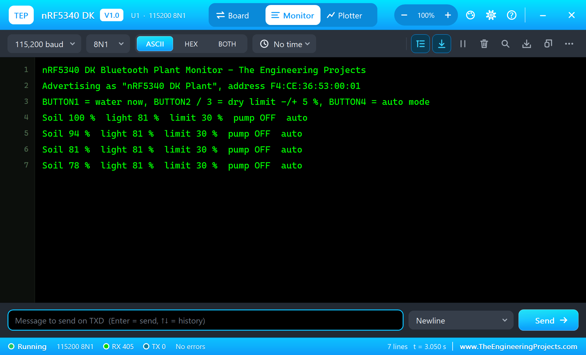
Connect the Phone
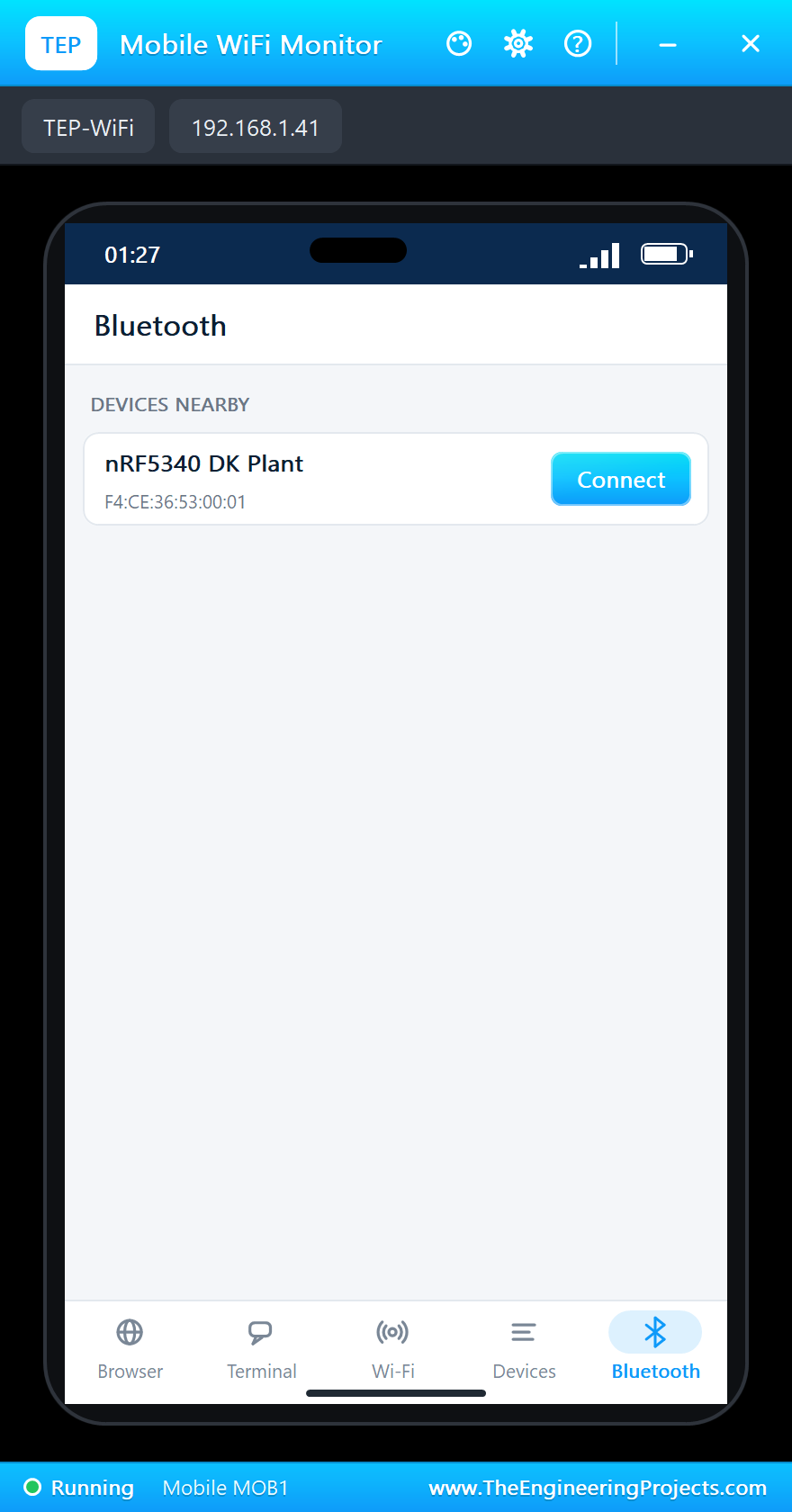
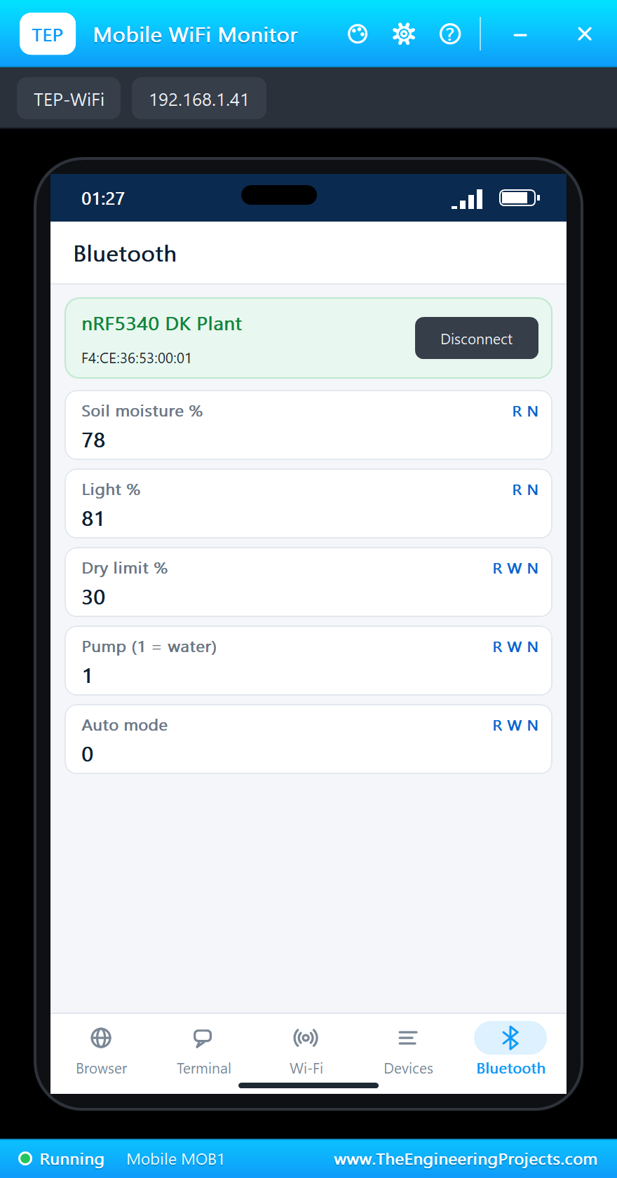
Click the phone on the sheet and tap the Bluetooth app. The monitor is in the list as nRF5340 DK Plant:
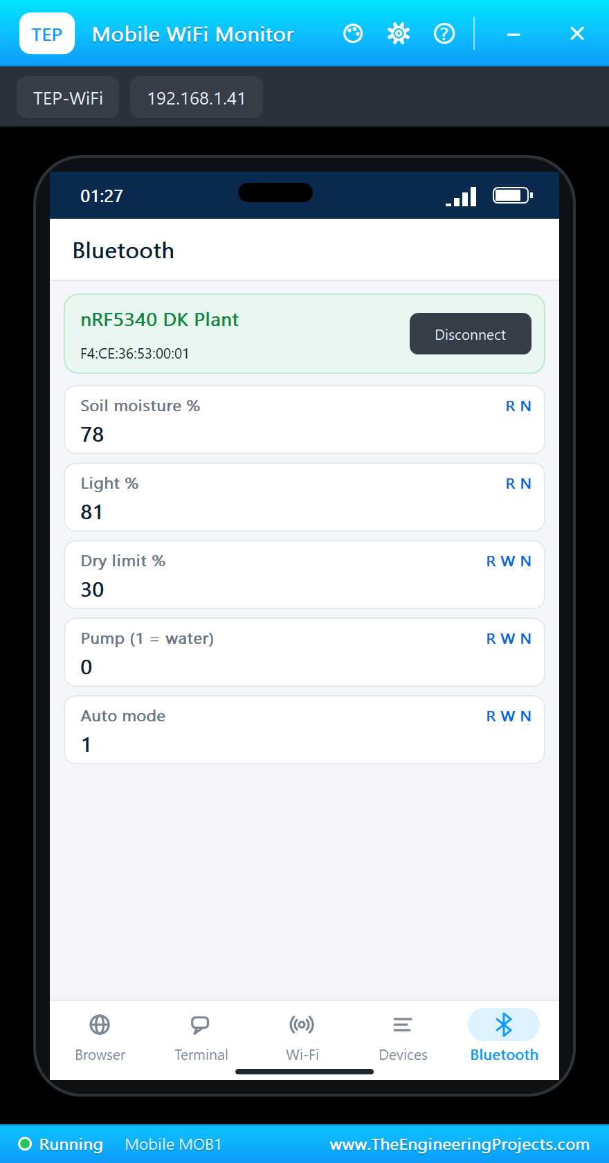
Tap Connect. LED1 stops blinking, and the phone lists the five characteristics with their labels:
Water by Hand
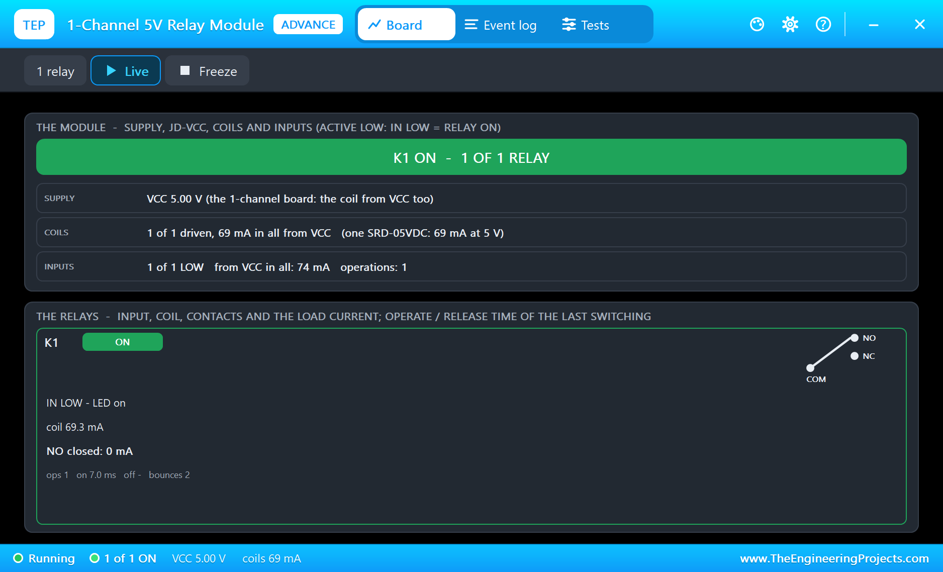
Click BUTTON4 on the board to switch to manual mode, then BUTTON1. The relay clicks, LED3 lights, and after four seconds the pump stops again. BUTTON3, clicked twice, raises the dry limit from 30 % to 40 %, and BUTTON4 brings auto mode back (we left out the repeated status lines):
>> BUTTON4
   BUTTON4: auto mode OFF (manual)
>> BUTTON1
>> Pump ON (BUTTON1)
Soil 78 %  light 81 %  limit 30 %  pump ON  manual
>> Pump OFF (watered)
>> BUTTON3
   BUTTON3: dry limit 35 %
>> BUTTON3
   BUTTON3: dry limit 40 %
>> BUTTON4
   BUTTON4: auto mode ON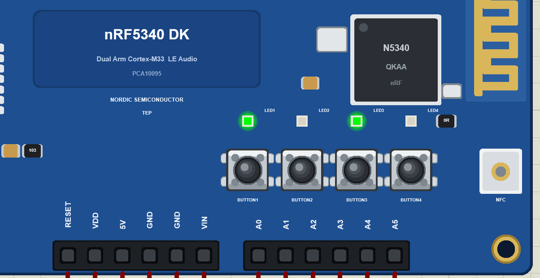
Dry Soil
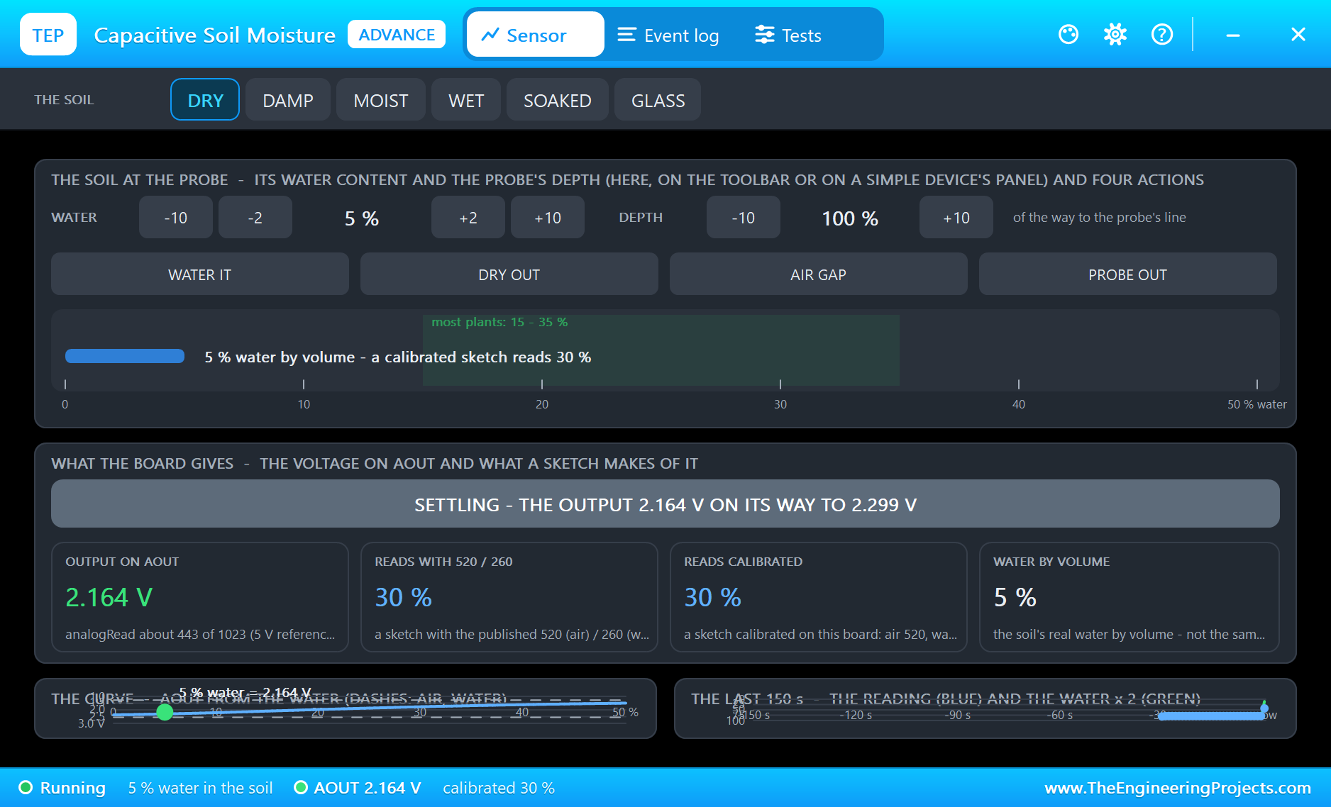
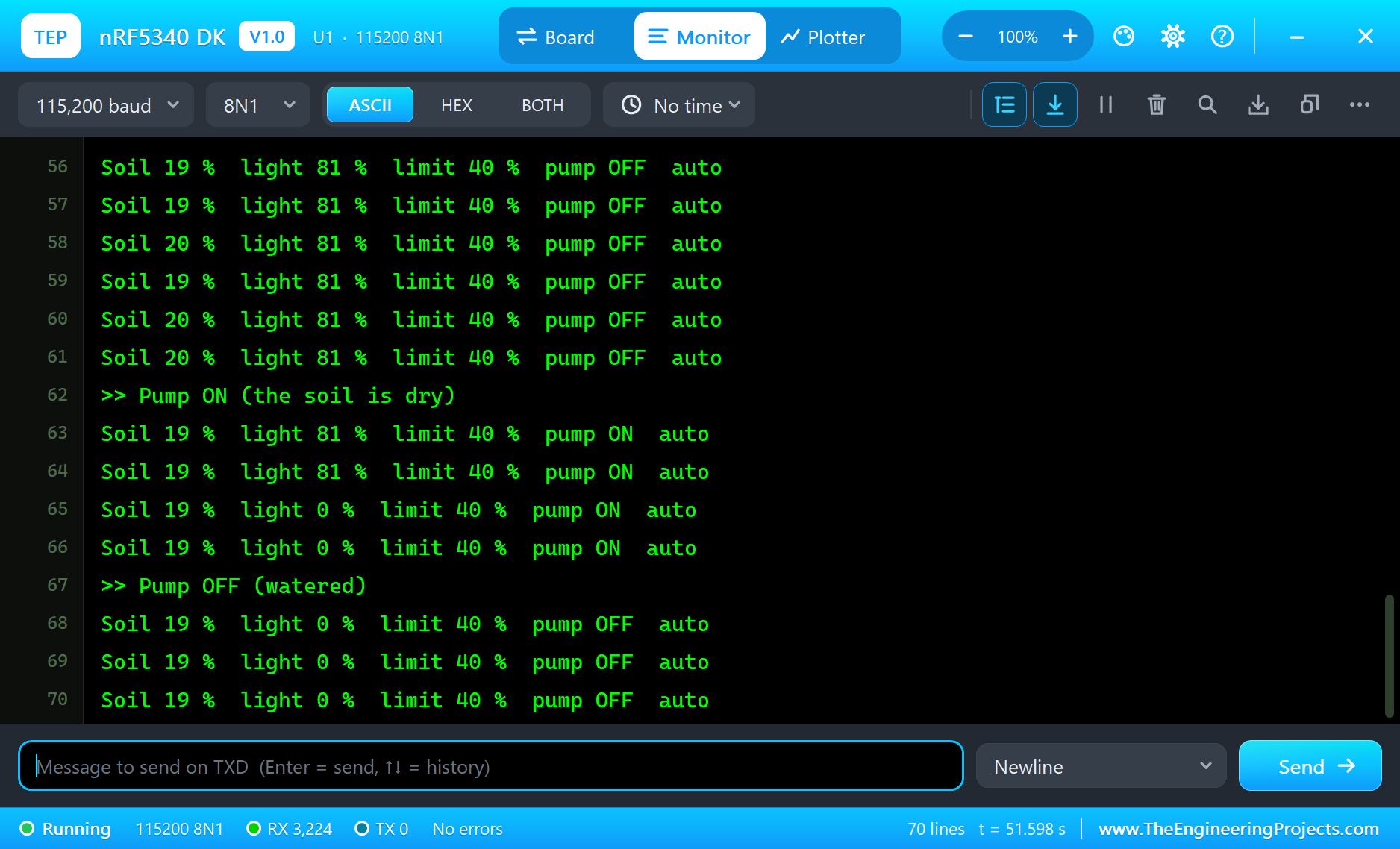
Open the soil sensor's pop-up and click DRY. Within three seconds the reading falls from 78 % to 19 %, below the 40 % limit, and LED2 lights. The pump does not start at once: the hand watering a moment ago began a 15-second rest. When the rest is over, the monitor starts the pump by itself, and four seconds later it stops (repeated lines left out):
Soil 43 %  light 81 %  limit 40 %  pump OFF  auto
Soil 22 %  light 81 %  limit 40 %  pump OFF  auto
Soil 19 %  light 81 %  limit 40 %  pump OFF  auto
>> Pump ON (the soil is dry)
Soil 19 %  light 81 %  limit 40 %  pump ON  auto
Soil 19 %  light 0 %  limit 40 %  pump ON  auto
>> Pump OFF (watered)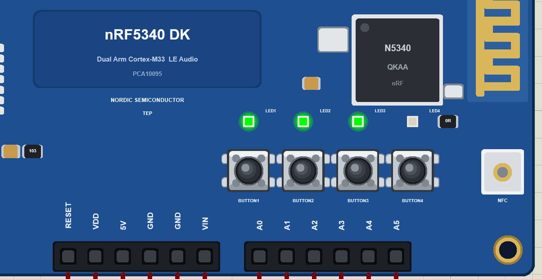
A Dark Room
Now open the LDR's pop-up and click Night. The light reading drops to almost nothing, and LED4 lights: in a real home this is the moment to switch on a grow light.
Here is the complete circuit while the simulation runs:
Try It Yourself
- Change
WATER_MSandREST_MSand watch how the watering rhythm changes. - Tap the phone's Pump row, type 1 and press Send: the phone waters the plant.
- Make LED4 blink instead of glowing when the room is dark for a long time.
- Hold BUTTON1 for two seconds to water for twice as long.
Ideas to Extend the Monitor
- Add a second soil sensor on A2 for a second pot, with its own dry limit.
- Put a BME280 on SDA and SCL and send the air temperature and humidity too.
- Count the waterings of the day and let the phone read the number.
- Switch a grow light on a second relay when LED4 lights.
Your Own Sketches
Write the sketch in the Arduino IDE with the board Nordic nRF5340 DK (TEP Proteus), use Sketch > Export Compiled Binary and set the part's PROGRAM property to the .hex. Use the DK's names: LED1 to LED4, BUTTON1 to BUTTON4, SDA, SCL and the header's D and A pins. For a real board, Nordic's nRF Connect SDK builds your application for the application core and adds the Bluetooth controller for the network core; the logic of your sketch, the GATT plan and the button scheme carry straight over.
Things to Know Before Using a Real nRF5340 DK
- 3.3 V logic: the pins of the nRF5340 are not 5 V tolerant, so check a shield before you plug it in.
- Two cores, two images: a real project flashes the application core and the network core, which the SDK does for you.
- Calibrate the soil sensor: every capacitive sensor reads a little differently, so print its raw readings in air and in water and put them in
SOIL_DRYandSOIL_WET. - Water and electronics: keep the pump's supply and the relay away from the pot, and use a low-voltage pump.
- Range is real: walls and bodies weaken 2.4 GHz signals, so test a real node where it will live.
Properties of the nRF5340 DK
| Property | What it does |
|---|---|
| PROGRAM | the sketch: a .hex from TEP Boards for Proteus (board "Nordic nRF5340 DK") |
| MONITOR, BAUD, AUTOOPEN | the built-in serial monitor: on, its baud rate (115200), open at Run |
Troubleshooting
- The phone's list is empty: call
BLE.begin(), set a local name, callBLE.advertise()and keepBLE.poll()inloop(). Use the TEPNET.DLL from this package. - The soil reads 100 % for the first seconds: the capacitive sensor settles after power-up, as a real one does.
- The pump runs backwards: the relay module switches on when IN is LOW.
- A button does nothing: use
INPUT_PULLUPand act whendigitalRead()is LOW. - A number goes wrong above 32767: int is 16 bits in the simulation - use long.
Limitations of the Simulation
- The board is a Bluetooth LE peripheral, and one phone is the central. The board cannot be a central itself in this version.
- Your sketch is one program: the real chip's two cores are not split. LE Audio, Thread, Zigbee, NFC, the USB device classes and the QSPI flash are drawn, not modelled, and radio range is not simulated.
- Your sketch gets 8 KB of RAM in the simulation, and int is 16 bits there.
- nRF5340 and Nordic Semiconductor are names of Nordic Semiconductor ASA, Arduino of Arduino, and the Bluetooth word mark belongs to Bluetooth SIG; this library is not made or endorsed by them or by Labcenter.
- Tested in Proteus 8.5 in November 2026 (the demo as shipped, about 52 s of simulation). Proteus 7 is not supported.
So, that was all about the nRF5340 DK Library for Proteus. I hope it helps you try your Bluetooth LE ideas in a simulation before you buy a board - the GATT design, the buttons, the LEDs and real sensors, all on one sheet. If you have any questions, ask in the comments and I will help you out. Till the next tutorial, take care and have fun!

Comments
0