


nRF52 DK Library for Proteus: nRF52832 Bluetooth LE Simulation


Hello friends, I hope you all are doing great. Today, I am going to share the nRF52 DK Library for Proteus, so you can run a Bluetooth LE simulation of Nordic Semiconductor's classic development kit. The nRF52 DK carries the nRF52832, an Arm Cortex-M4F at 64 MHz with Bluetooth LE and NFC, the chip inside countless wearables, beacons and sensors. With this library it runs your Arduino sketch in Proteus 8.5, talks to a phone over Bluetooth LE, and its four LEDs and four buttons behave exactly like on the real board - even the way they share the Arduino header pins.
nRF52 DK Library for Proteus
Latest version: V1.0 (November 2026, this tutorial)
Helping Tools
- Laptop WiFi Monitor: a laptop on the Wi-Fi of your design: a browser, a TCP / UDP terminal and ping
- Mobile WiFi Monitor: a smartphone that opens the pages of your board and sends it commands
- Serial Monitor Advance: a serial terminal window for the UART of your board
For the demo we built a Bluetooth classroom poll. The four buttons are the answers A to D, the LED of the leading answer lights up, and the teacher's phone shows every count as the votes come in.
NOTICE: Proteus has no nRF52832 model, so our team has put a lot of effort into building this board ourselves: the pins, the LEDs, the buttons and Bluetooth LE are all our own model, and your sketch compiles with our free TEP Boards for Proteus add-on. Your feedback is the fuel that keeps us going, so please tell us what you think in the comments below. And if our free libraries help you, you can buy us a coffee. So, let's get started with the nRF52 DK Library for Proteus:
What is the nRF52 DK?
The nRF52 DK (PCA10040) is Nordic Semiconductor's development kit for the nRF52832, one of the most widely used Bluetooth LE chips. The nRF52832 combines an Arm Cortex-M4F at 64 MHz, 512 KB of flash, 64 KB of RAM, a 2.4 GHz radio and NFC. The kit adds a J-Link interface MCU with its USB port for programming, debugging and a virtual serial port, a power switch, four buttons, four green LEDs, a PCB antenna and Arduino Uno compatible headers, so shields plug straight in.
| Part | The real nRF52 DK | In the library |
|---|---|---|
| SoC | nRF52832: Cortex-M4F 64 MHz, 512 KB flash, 64 KB RAM | your Arduino sketch |
| Radio | Bluetooth LE, NFC | ArduinoBLE |
| LEDs | LED1 to LED4 on P0.17 to P0.20, active LOW | LED1 to LED4 = D6 to D9 |
| Buttons | BUTTON1 to BUTTON4 on P0.13 to P0.16, active LOW | BUTTON1 to BUTTON4 = D2 to D5 |
| Headers | Arduino Uno layout | D0 to D13, A0 to A5, SDA, SCL |
| USB | J-Link interface MCU, virtual COM port | the serial monitor |
LEDs and Buttons on the Header Pins
The nRF52 DK has a peculiarity that every user meets sooner or later: its buttons and LEDs are wired to the same GPIOs as some Arduino header pins. BUTTON1 to BUTTON4 sit on P0.13 to P0.16, which are D2 to D5, and LED1 to LED4 on P0.17 to P0.20, which are D6 to D9 (Zephyr's board files for the kit list exactly this). Our library reproduces it: pressing BUTTON1 pulls D2 low, and writing D6 low lights LED1. A sketch that works in the simulation therefore behaves the same on the real kit.
Why the nRF52832 Is Everywhere
Since its launch the nRF52832 has become one of the standard chips for Bluetooth LE products: fitness trackers, smart locks, beacons, medical sensors and remote controls. It is small, very efficient and well supported by Nordic's software, and many modules from other makers are built around it. Learning it on the DK teaches skills that transfer to thousands of products.
Bluetooth LE in a Few Words
A Bluetooth LE device such as our DK is a peripheral: it advertises a short packet with its name a few times a second. A central, usually a phone, scans for these packets and connects. Once connected, the peripheral offers its data in services, each holding characteristics - small values the phone can read, write or subscribe to. Our poll has one service with five characteristics: the four counts and the leader. When a value changes, the DK notifies the phone, which updates its screen at once.
The Interface MCU
The square chip near the USB port is the interface MCU. It programs the nRF52832 over SWD, lets a debugger stop the program and look at its variables, and turns the chip's UART into a virtual serial port on the PC. That is why one USB cable is all the kit needs. In our simulation the USB port opens the serial monitor, where the sketch's Serial output appears.
Where Is It Used?
Students use the nRF52 DK in courses on embedded systems and wireless communication, engineers use it to evaluate the chip before a custom board, and makers use it with Arduino shields thanks to its headers. For the bigger sister with USB and more memory, see our nRF52840 DK Library for Proteus; for a Bluetooth kit from Silicon Labs, see our xG26 Dev Kit Library for Proteus.
A simulation lets you build the logic and the phone link before the kit is on the desk: the buttons, the LEDs and the Bluetooth service. When the sketch works in the Proteus simulation, the real board only has to confirm it.
Features of the nRF52 DK Library for Proteus
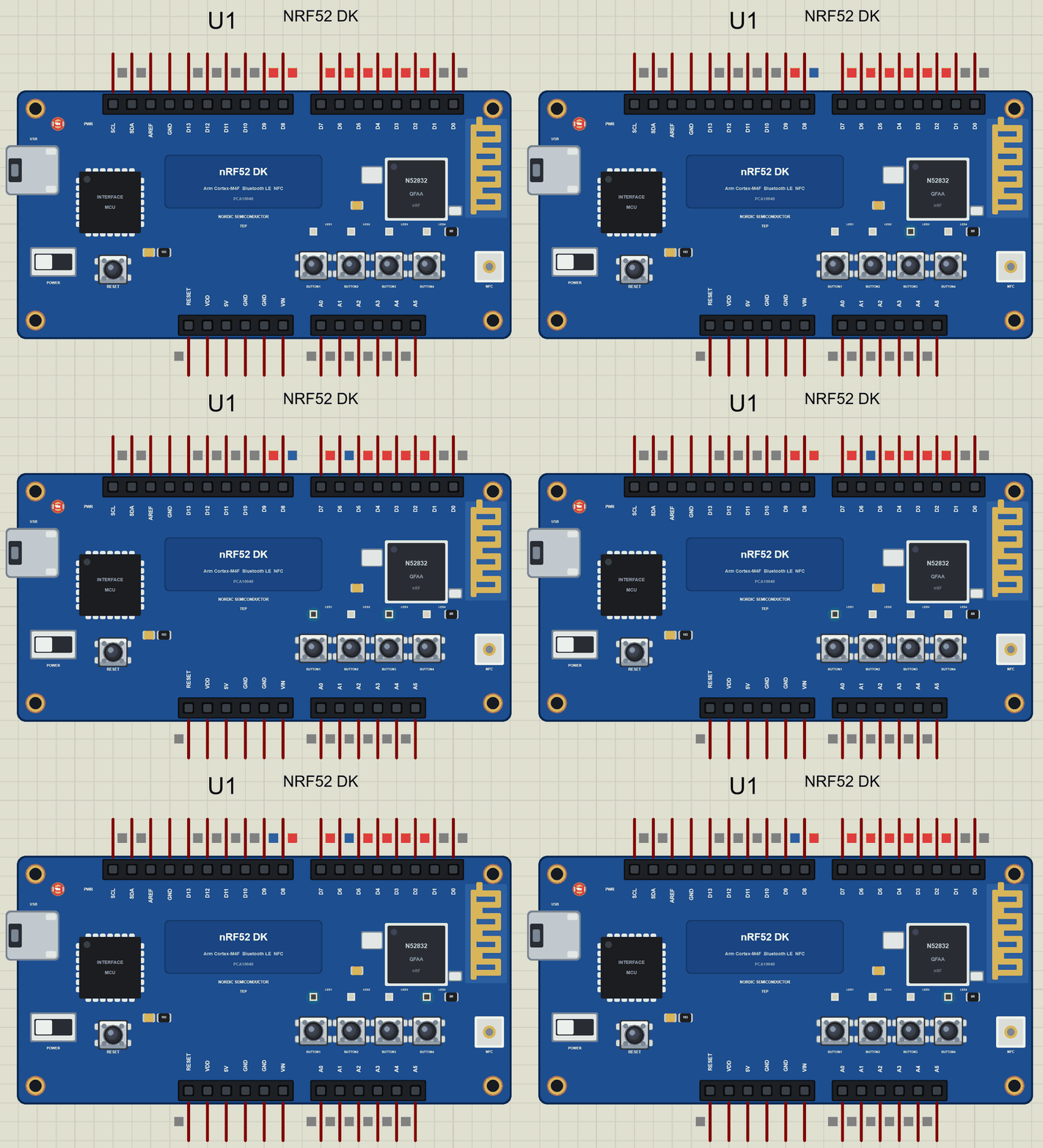
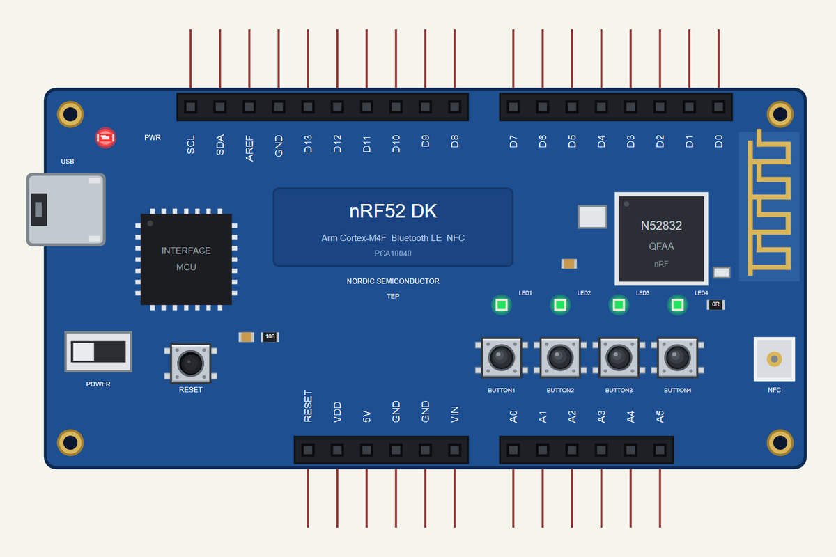
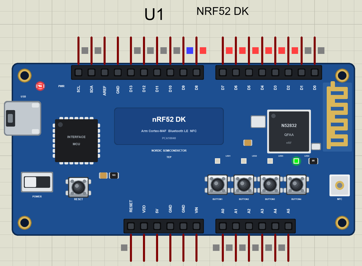
- The board as it looks: the blue DK with the interface MCU and its USB port, the nRF52832, the PCB antenna, the power switch, RESET, the four buttons, the four green LEDs, the NFC pad and the Arduino headers, drawn compact, with our small TEP signature.
- Your sketch: a .hex for "Nordic nRF52 DK (TEP Proteus)" with D0 to D13, A0 to A5, LED1 to LED4 and BUTTON1 to BUTTON4.
- True to the board: the buttons are D2 to D5 and the LEDs D6 to D9, both active LOW, as on the real DK.
- Bluetooth LE: ArduinoBLE, with our phone as the central.
- A complete package: about 3.4 MB with the part, the add-on, the phone and the demo, without the source code of the models.
The nRF52 DK in Proteus Simulation
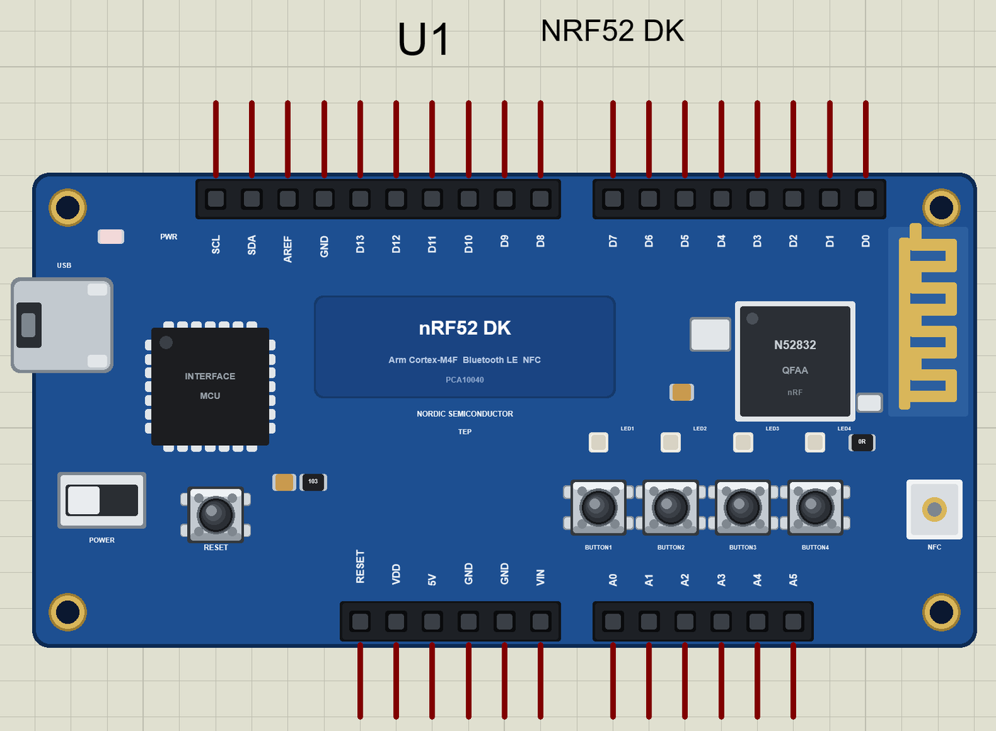
Search NRF52 in Pick Devices; the device NRF52 DK is in TEPNRF52DK.LIB (Microprocessor ICs, Bluetooth Boards), with the prefix U. The USB port opens the serial monitor. The DK has no Wi-Fi, so there is no Wi-Fi panel.
The Pins
| Pins | The real DK | What the library does with them |
|---|---|---|
| D0, D1 | P0.11, P0.12 | Serial1 RX and TX, or GPIO |
| D2 to D5 | P0.13 to P0.16 | GPIO, PWM, interrupt - and BUTTON1 to BUTTON4 |
| D6 to D9 | P0.17 to P0.20 | GPIO, PWM, interrupt - and LED1 to LED4 |
| D10 to D13 | P0.22 to P0.25 | GPIO, PWM; SPI SS, MOSI, MISO, SCK |
| A0 to A5 | P0.03, P0.04, P0.28 to P0.31 | analogRead 0 to 1023 for 0 to 3.3 V, or GPIO |
| SDA, SCL | P0.26, P0.27 | Wire |
Download nRF52 DK Library for Proteus
Click the button below to download nRF52-DK-Library-for-Proteus-v1.0.zip (about 3.4 MB, without the source code of the models):
nRF52 DK Library for Proteus V1.0- README.txt: installation, the demo, the pins, the properties, troubleshooting and the limits.
- Proteus Library Files:
TEPNRF52DK.LIBand the phone and laptop (TEPMOBILE.LIB,TEPLAPTOP.LIB). - Proteus Model Files:
TEPNET.DLL, the model of the board, the phone and the laptop. - Arduino Code: the demo sketch and the TEP Boards for Proteus add-on 1.81.0, with ArduinoBLE.
- Proteus Simulation: the demo project, its HEX file and a copy of the DLL.
No Proteus yet? Read How to Download and Install Proteus 7 and 8. New to libraries? Follow How to Install a New Library in Proteus.
How to Install nRF52 DK Library for Proteus
- Close Proteus and extract the whole zip file, for example to your Desktop.
- Copy the files from Proteus Library Files into the LIBRARY folder of Proteus.
- Copy
TEPNET.DLLfrom Proteus Model Files into the MODELS folder, replacing an older one. - Delete
TEPNRF52DK.IDXfrom the LIBRARY folder if it is there. - For your own sketches, copy Arduino Code\TEP Boards for Proteus\hardware into your Arduino sketchbook (Documents\Arduino) and restart the Arduino IDE; the board is Nordic nRF52 DK (TEP Proteus).
- Start Proteus, press P and search for NRF52.
Demo: a Bluetooth Classroom Poll in Simulation
Quick polls keep a class awake: the teacher asks a question with four answers, everyone votes, and the result is there at once. Our poll uses only the DK itself - four buttons, four LEDs - and sends the counts to the teacher's phone over Bluetooth LE.
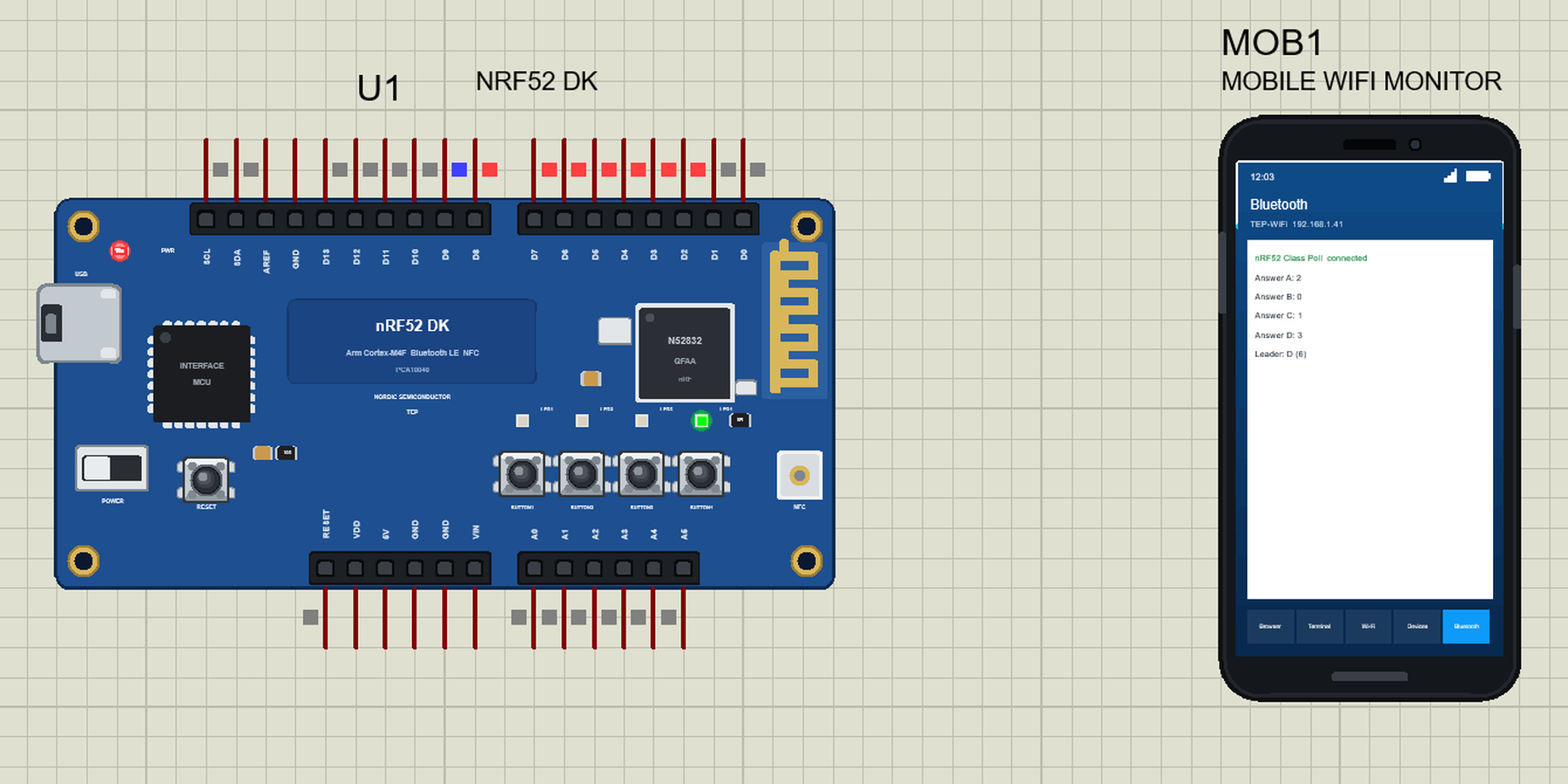
Open nRF52-DK-BLE-Class-Poll.pdsprj. U1 runs DK52_Class_Poll.hex, and MOB1 is our Mobile WiFi Monitor, the teacher's phone; its Bluetooth app connects to the DK. No wires: the buttons and the LEDs are on the board.
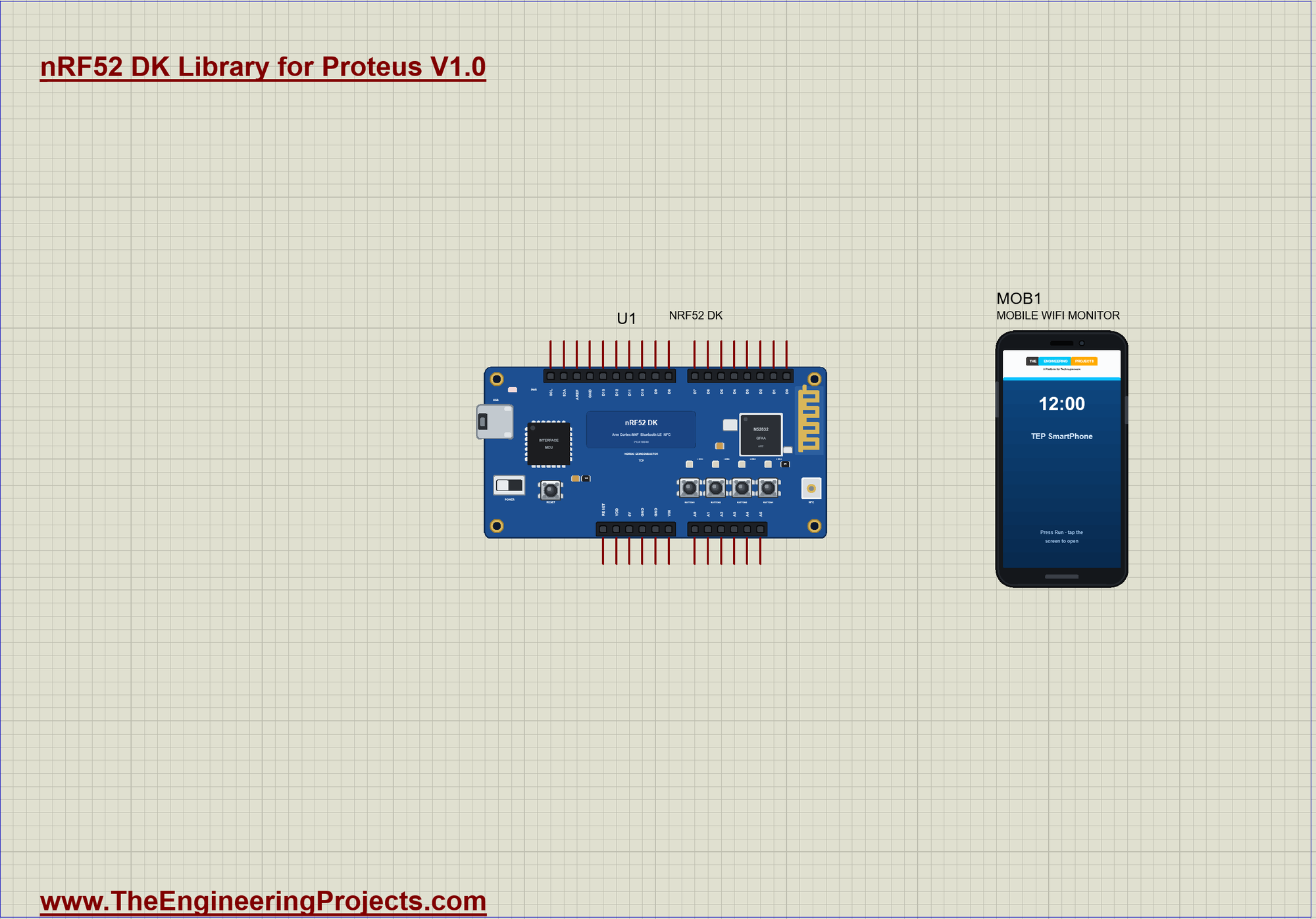
| On the board | What it does |
|---|---|
| BUTTON1 to BUTTON4 | a vote for A, B, C or D |
| LED1 to LED4 | the leading answer; every leader lights in a tie |
| the phone | the four counts and the leader with the total |
The Answers, the LEDs and the Buttons
Three small arrays tie everything together: the LED, the button and the letter of each answer. On this DK the names LED1 and BUTTON1 are header pins, so the arrays are all the sketch needs:
const byte LEDS[4] = {LED1, LED2, LED3, LED4};
const byte BUTTONS[4] = {BUTTON1, BUTTON2, BUTTON3, BUTTON4};
const char ANSWER[4] = {'A', 'B', 'C', 'D'};
The Bluetooth Service
One service carries a characteristic for each answer and one for the leader. Each has a 0x2901 description, so the phone shows "Answer A" instead of a long UUID:
BLEService pollService("19B10070-E8F2-537E-4F6C-D104768A1214");
BLEIntCharacteristic countA("19B10071-E8F2-537E-4F6C-D104768A1214", BLERead | BLENotify);
BLEIntCharacteristic countB("19B10072-E8F2-537E-4F6C-D104768A1214", BLERead | BLENotify);
BLEIntCharacteristic countC("19B10073-E8F2-537E-4F6C-D104768A1214", BLERead | BLENotify);
BLEIntCharacteristic countD("19B10074-E8F2-537E-4F6C-D104768A1214", BLERead | BLENotify);
BLEStringCharacteristic leaderChar("19B10075-E8F2-537E-4F6C-D104768A1214", BLERead | BLENotify, 16);
Finding the Leader
showLeader() finds the highest count, lights the LED of every answer that has it - more than one in a tie - and sends the leader and the total to the phone:
void showLeader() {
  int best = 0, total = 0;
  for (byte k = 0; k < 4; k++) { total += votes[k]; if (votes[k] > best) best = votes[k]; }
  String leader = "";
  for (byte k = 0; k < 4; k++) {
    const bool leads = best > 0 && votes[k] == best;
    digitalWrite(LEDS[k], leads ? LOW : HIGH);              // the leaders' LEDs light (LOW = on)
    if (leads) { if (leader.length()) leader += '+'; leader += ANSWER[k]; }
  }
  if (!leader.length()) leader = "none";
  leaderChar.writeValue(leader + " (" + String(total) + ")");
  Serial.print(F("   ")); Serial.print(standings()); Serial.print(F("   leader ")); Serial.println(leader);
}
Reading the Buttons
loop() keeps Bluetooth running and counts a vote on each change to LOW, the moment of the press:
void loop() {
  BLE.poll();
  const bool connected = BLE.connected();
  if (connected != wasConnected) { wasConnected = connected; Serial.println(connected ? F("Phone connected") : F("Phone disconnected")); }
  for (byte k = 0; k < 4; k++) {
    const bool now = digitalRead(BUTTONS[k]);
    if (now == lastButton[k]) continue;
    lastButton[k] = now;
    if (now == LOW) vote(k);                                // act on the press
  }
}
Run the Simulation
Press Run. The serial monitor - the same window as our TEP Serial Monitor Advance for Proteus - shows the name the DK advertises:
nRF52 DK Bluetooth Classroom Poll - The Engineering Projects
Advertising as "nRF52 Class Poll"   BUTTON1 .. BUTTON4 = answers A .. D
Phone connected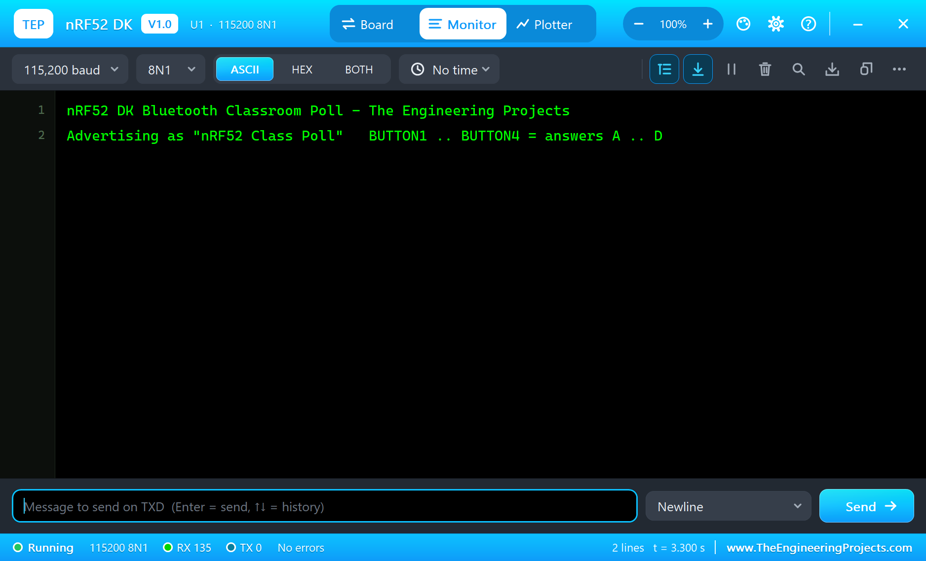
Connect the Phone
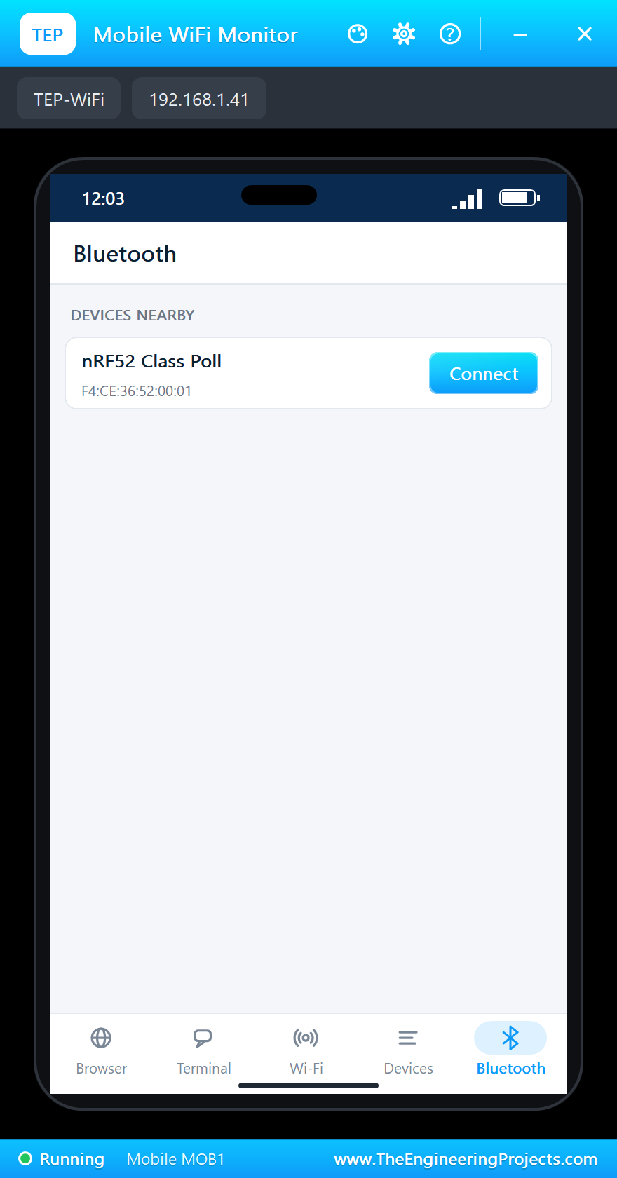
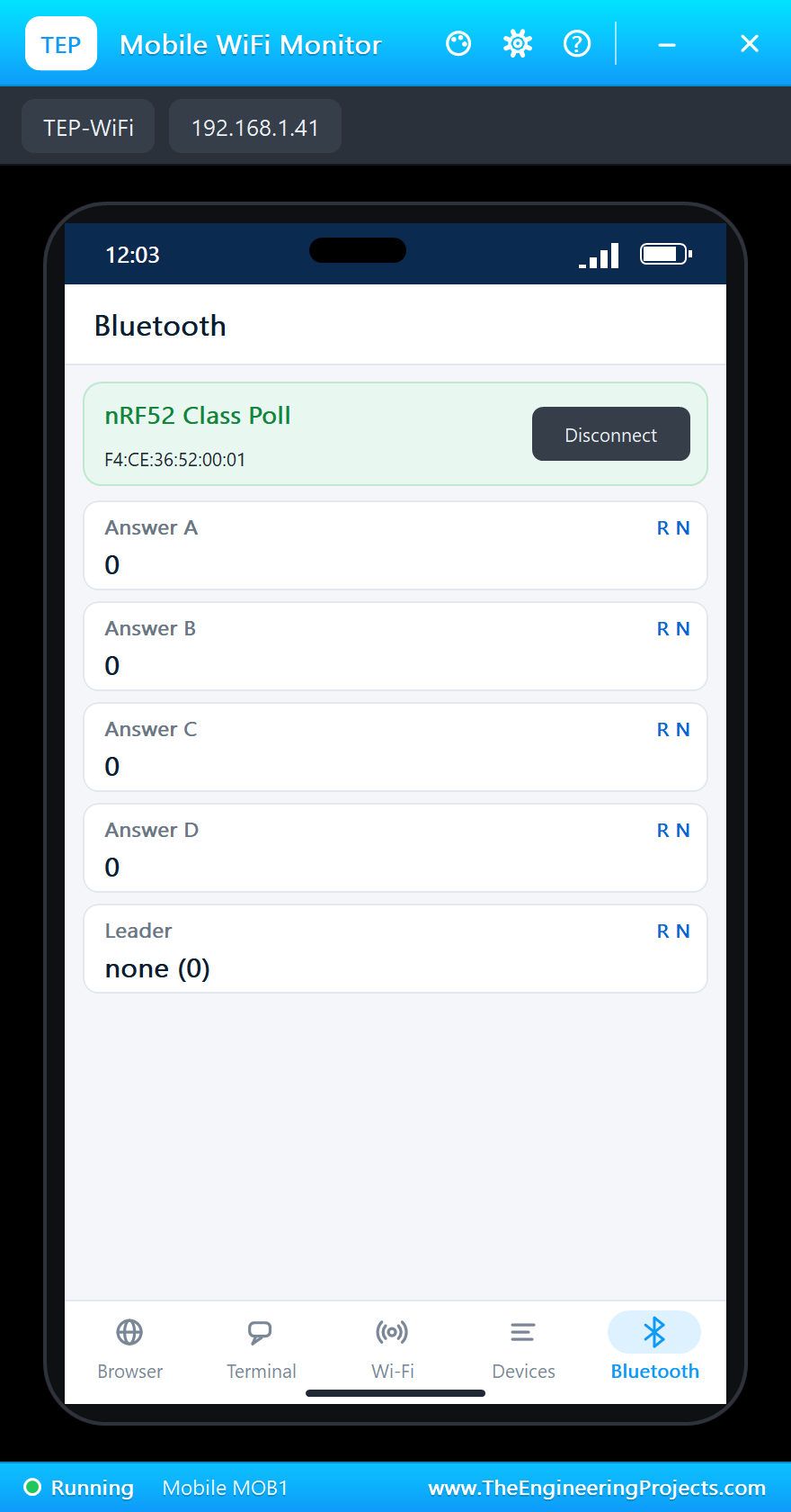
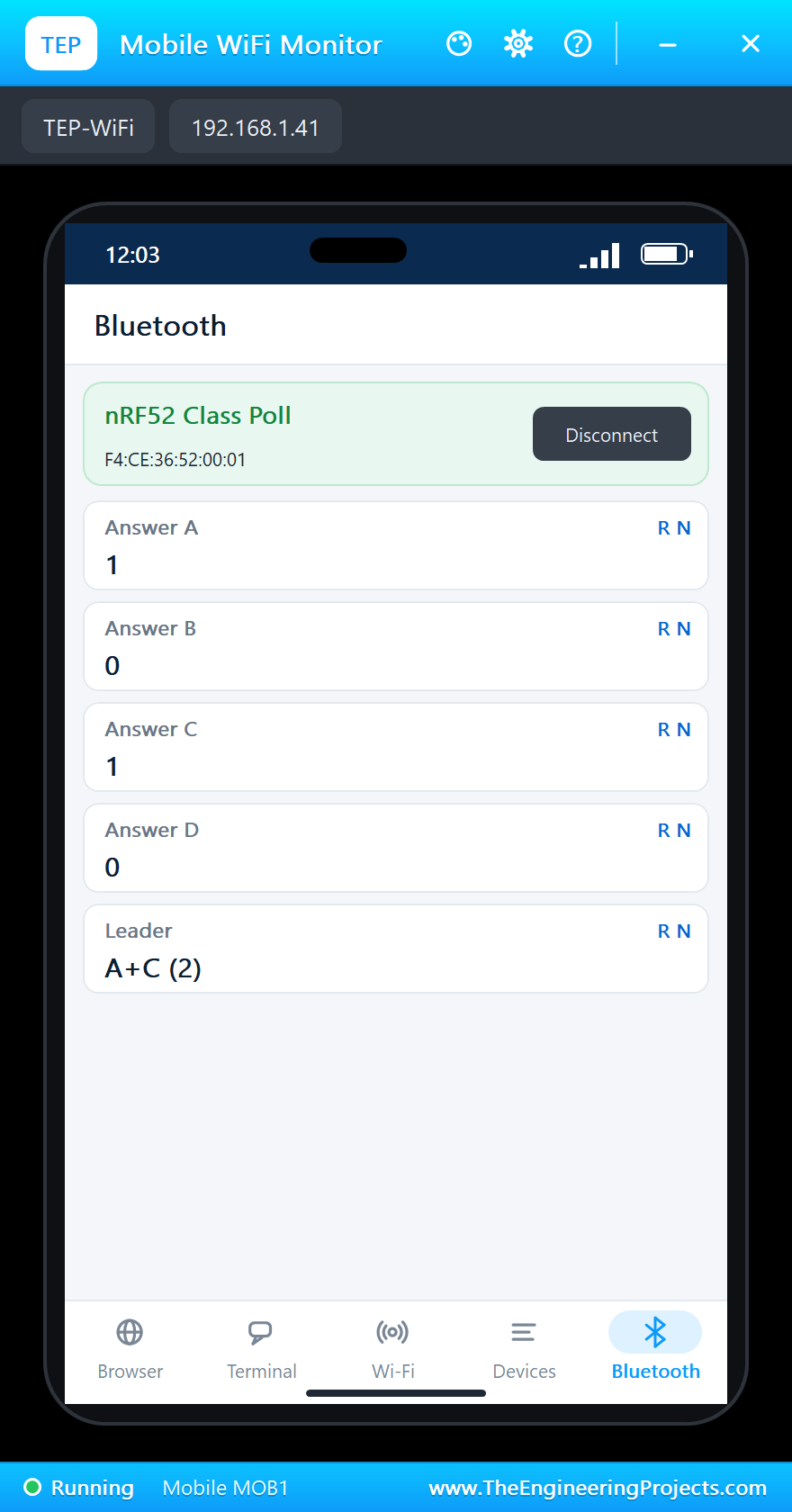
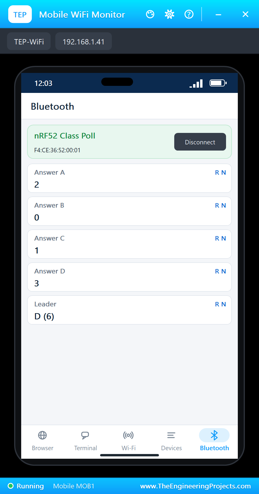
Click the phone, open its Bluetooth app and press SCAN. "nRF52 Class Poll" appears; tap it to connect. The phone lists Answer A to D and the Leader, all at zero:
Vote
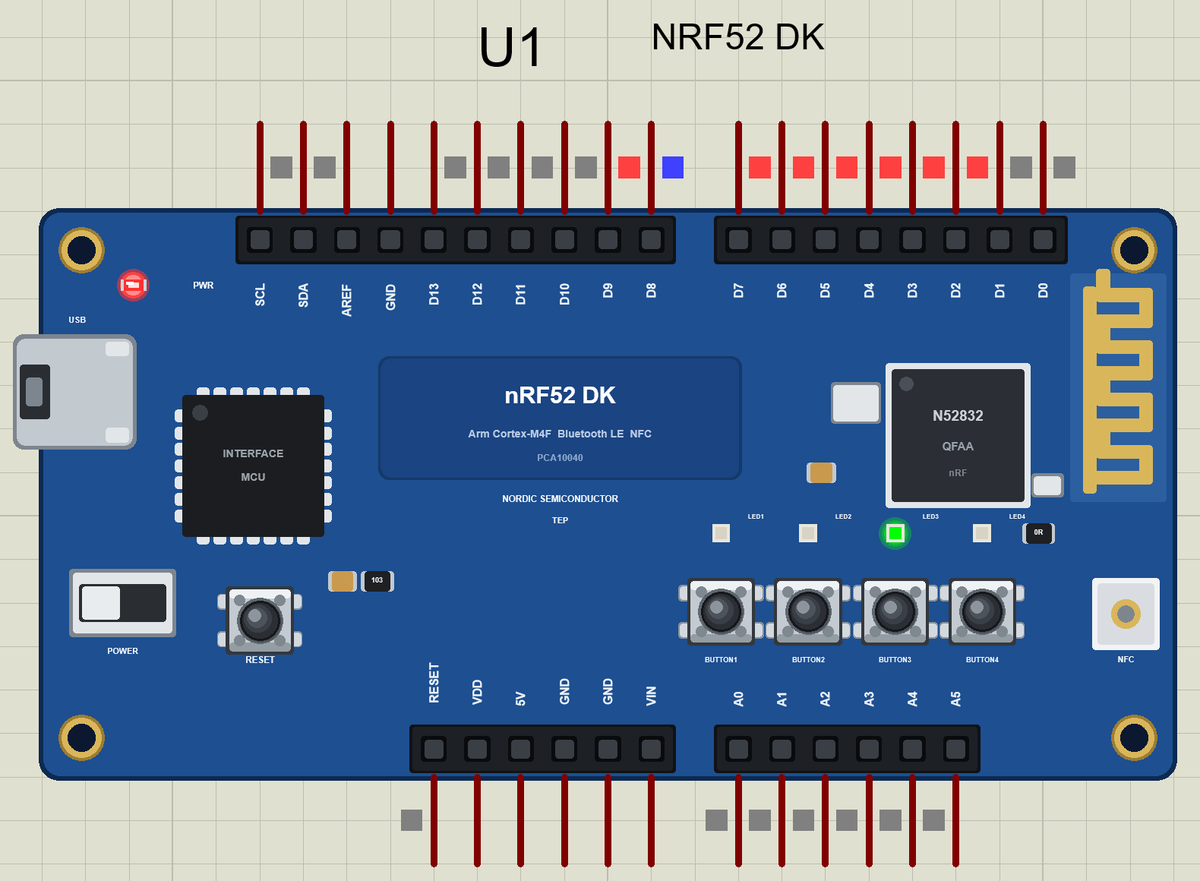
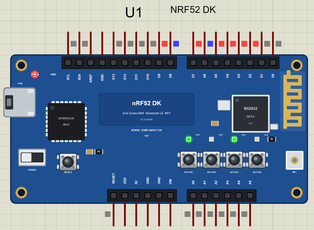
Click BUTTON3: a vote for C, and LED3 lights. Click BUTTON1: A and C now have one vote each, so both LED1 and LED3 light, and the phone shows the leader "A+C":
D Takes the Lead
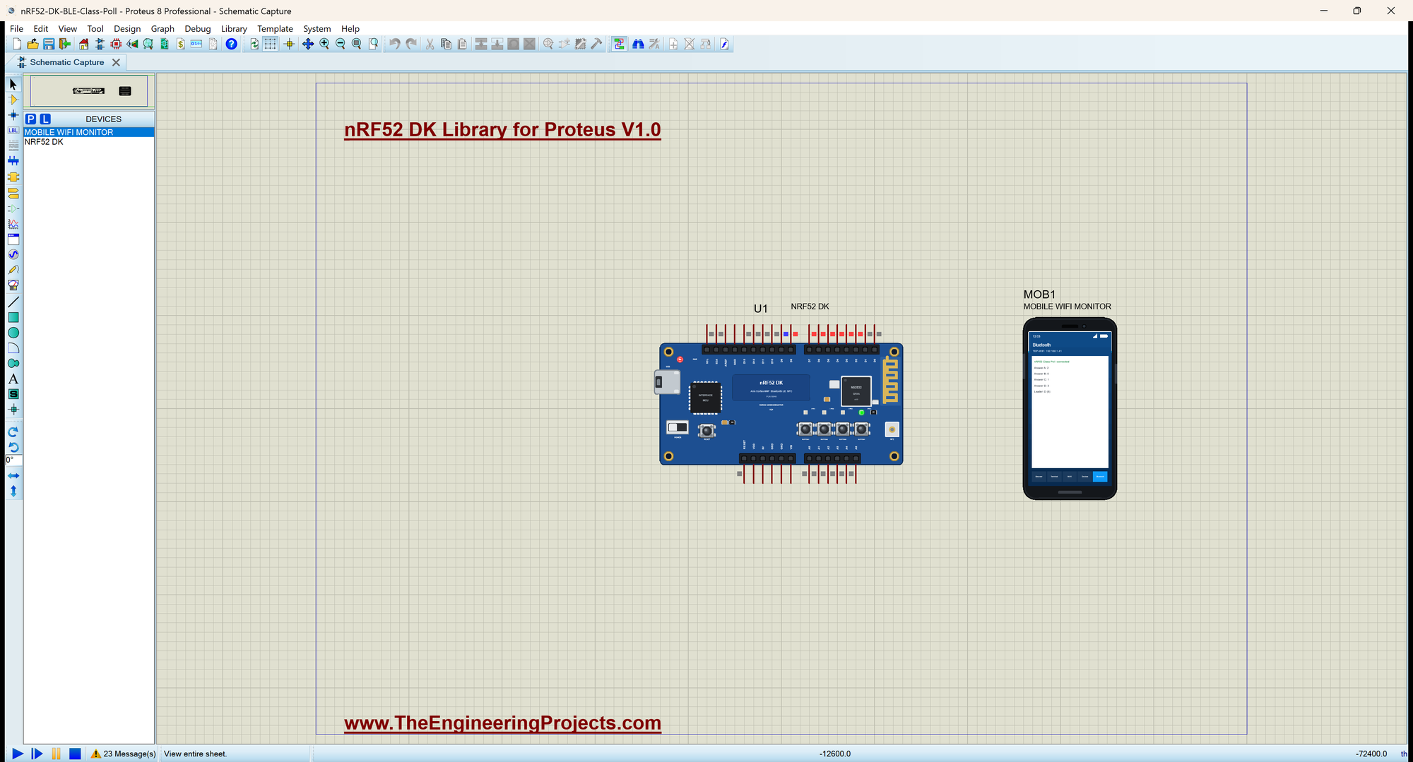
One more vote for A puts it ahead. Then three votes for D: first a tie with A, then D alone in front, and only LED4 stays on. Here is the complete circuit while the simulation runs:
>> Vote for C (1)
   A 0  B 0  C 1  D 0   leader C
>> Vote for A (1)
   A 1  B 0  C 1  D 0   leader A+C
>> Vote for A (2)
   A 2  B 0  C 1  D 0   leader A
>> Vote for D (1)
   A 2  B 0  C 1  D 1   leader A
>> Vote for D (2)
   A 2  B 0  C 1  D 2   leader A+D
>> Vote for D (3)
   A 2  B 0  C 1  D 3   leader D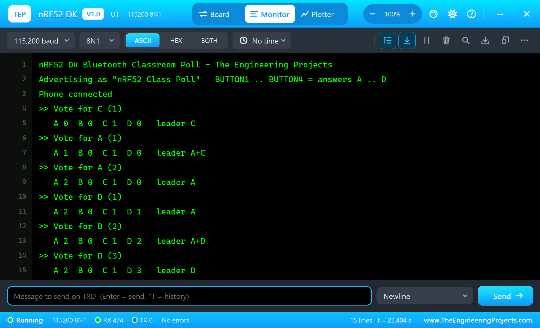
Why Active-LOW LEDs?
On the DK each LED runs from the 3.3 V supply through a resistor to its GPIO, so the chip lights it by pulling the pin LOW. A GPIO can usually sink a little more current than it can source, and the LED keeps its own supply. That is why the sketch writes LOW for "on" and HIGH for "off" - the same in the simulation as on the real board.
Ties and Fair Results
A poll that shows only one winner hides information: with two answers level, the class should see both. Lighting every leader in a tie is a small detail that makes the result honest, and the phone writes it as "A+C". The total in brackets shows how many students have voted, so the teacher knows when everyone is done.
Notifications Instead of Polling
Every characteristic is declared with BLENotify. When a count changes, the DK pushes the new value to the phone at once; the phone does not have to keep asking. That saves radio time and battery on both sides, and the teacher sees each vote appear immediately.
Sharing Pins Wisely
Because the buttons and LEDs are D2 to D9, a shield that uses those pins competes with them. On the real DK you choose: either use the buttons and LEDs, or free the pins for a shield. Our demo uses only the DK's own parts, so nothing conflicts. If you add your own parts in the simulation, put them on D10 to D13, A0 to A5 or the I2C pins first.
One Vote per Press
The sketch counts a vote only on the change from HIGH to LOW, not while a button is held, so a long press is still one vote. Real buttons also bounce for a few milliseconds; on the real kit a short delay or a timestamp check after each press keeps one press from counting twice.
From Poll to Product
Commercial classroom clickers work the same way: every student has a small Bluetooth or radio button pad, and a receiver collects the answers for the teacher's screen. The nRF52832 is a typical chip for such pads because it runs for months on a coin cell. Our demo turns the idea around - one board with four buttons for a small group - but the counting, the leader and the notifications are the same building blocks.
Try It Yourself
- Add a reset: hold BUTTON1 and BUTTON4 together for two seconds to start a new question.
- Let the phone write a "question number" characteristic and print it on the monitor.
- Show the percentage of each answer on the phone instead of the count.
- Blink the leading LED when one answer has more than half of the votes.
Ideas to Extend the Poll
- Connect several DKs, one per table, and let a central board add their votes.
- Add a small display on I2C that shows the bar chart in the classroom.
- Store the results of each question in a list and send them all at the end of the lesson.
- Use NFC on the real kit to let students tap a phone to see the result.
Your Own Sketches
Write the sketch in the Arduino IDE with the board Nordic nRF52 DK (TEP Proteus), use Sketch > Export Compiled Binary and set the part's PROGRAM property to the .hex.
Moving to a Real nRF52 DK
- Install Nordic's nRF Connect SDK, or Zephyr with the board nrf52dk/nrf52832.
- Start from Nordic's Bluetooth peripheral samples and the button and LED samples.
- Move the logic of the demo across: the counts, the leader, the LEDs and the service.
- Program the DK through the interface MCU's USB and open its serial port at 115200 baud.
- Connect from a phone with a Bluetooth LE app and vote with the buttons.
The pins, the active-LOW LEDs and buttons and the Bluetooth service stay the same; on the real kit Nordic's SDK takes the place of the Arduino calls.
Things to Know Before Using a Real nRF52 DK
- Shared pins: D2 to D9 are the buttons and LEDs; plan your shields around them.
- 3.3 V logic: the header is 3.3 V; check every shield before you plug it in.
- Power: the DK runs from USB, from an external supply or from a CR2032 coin cell; choose with the power switch.
- NFC pins: P0.09 and P0.10 are the NFC antenna pins.
Properties of the nRF52 DK
| Property | What it does |
|---|---|
| PROGRAM | the sketch: a .hex from TEP Boards for Proteus (board "Nordic nRF52 DK") |
| MONITOR, BAUD, AUTOOPEN | the built-in serial monitor: on, its baud rate (115200), open at Run |
Troubleshooting
- The phone finds nothing: call
BLE.begin(), set a local name andBLE.advertise(); callBLE.poll()in loop(). - A button does nothing: use
pinMode(BUTTON1, INPUT_PULLUP)and act when it reads LOW; do not drive D2 to D5. - An LED lights by itself: something else drives D6 to D9 - they are the LEDs on this DK.
- The LEDs look inverted: they light when the pin is LOW, as on the real DK.
- A number goes wrong above 32767: int is 16 bits in the simulation - use long.
Limitations of the Simulation
- Bluetooth LE: the DK is a peripheral only, with one phone as the central.
- NFC and the current measurement header are drawn, not modelled.
- Your sketch gets 8 KB of RAM in the simulation, and int is 16 bits there.
- nRF52832 and Nordic Semiconductor are names of Nordic Semiconductor ASA and Arduino of Arduino, and the Bluetooth word mark belongs to Bluetooth SIG; this library is not made or endorsed by them or by Labcenter.
- Tested in Proteus 8.5 in November 2026 (the demo as shipped, about 18 s of simulation). Proteus 7 is not supported.
So, that was all about the nRF52 DK Library for Proteus. I hope it helps you try your Bluetooth ideas on the nRF52832 in a simulation before you buy the kit - the buttons, the LEDs and the phone, all on one sheet. If you have any questions, ask in the comments and I will help you out. Till the next tutorial, take care and have fun!

Comments
0