


LP-CC2652R7 Library for Proteus: TI CC2652R7 BLE Simulation


Hello friends, I hope you all are doing great. Today, I am going to share the LP-CC2652R7 Library for Proteus, so you can run a Bluetooth LE simulation of TI's CC2652R7 LaunchPad. The LP-CC2652R7 carries the CC2652R7, a SimpleLink wireless microcontroller for Bluetooth LE, Thread and Zigbee, on the red LaunchPad with the XDS110 debug probe, a red and a green LED, two buttons and 40 BoosterPack pins. With this library it runs your Arduino sketch in Proteus 8.5, talks Bluetooth LE to a phone, and its LEDs and buttons work with a click.
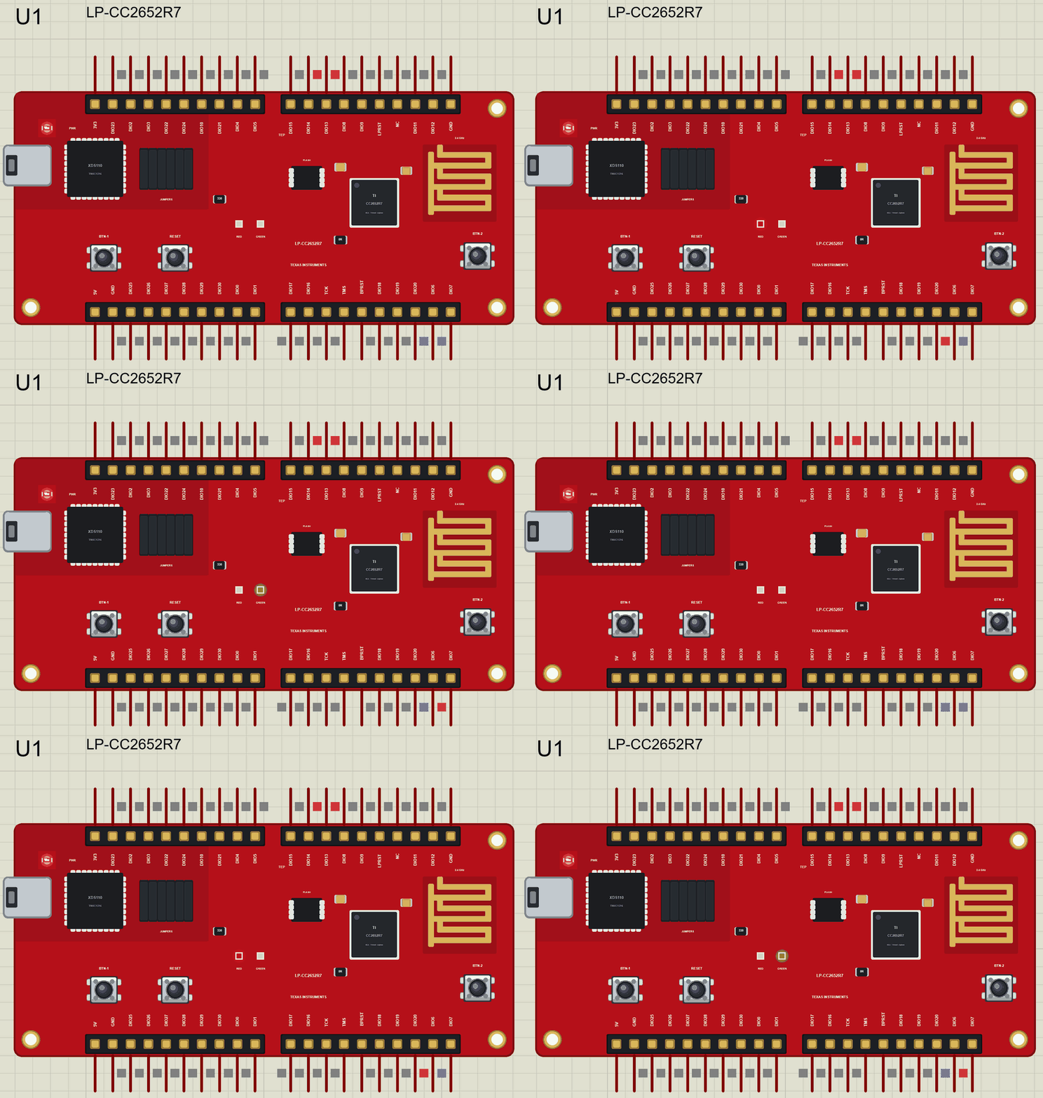
LP-CC2652R7 Library for Proteus
Latest version: V1.0 (November 2026, this tutorial)
Helping Tools
- Laptop WiFi Monitor: a laptop on the Wi-Fi of your design: a browser, a TCP / UDP terminal and ping
- Mobile WiFi Monitor: a smartphone that opens the pages of your board and sends it commands
- Serial Monitor Advance: a serial terminal window for the UART of your board
For the demo we built a Bluetooth nurse call button for a hospital room. The patient presses one button, the red LED lights and the nurse's phone shows the call; the nurse presses the other button on arrival, the green LED lights and the phone shows how long the patient waited.
NOTICE: Proteus has no CC2652R7 model, so our team has put a lot of effort into building this board ourselves: the BoosterPack pins, the LEDs, the buttons and Bluetooth LE are all our own model, and your sketch compiles with our free TEP Boards for Proteus add-on. Your feedback is the fuel that keeps us going, so please tell us what you think in the comments below. And if our free libraries help you, you can buy us a coffee. So, let's get started with the LP-CC2652R7 Library for Proteus:
What is the LP-CC2652R7?
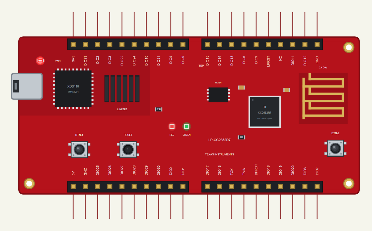
The LP-CC2652R7 is TI's LaunchPad development kit for the CC2652R7, a SimpleLink multi-standard wireless MCU. The chip has an Arm Cortex-M4F, 704 KB of flash, 152 KB of RAM, 31 GPIOs, a low-power sensor controller and cryptographic acceleration with secure boot, and its 2.4 GHz radio speaks Bluetooth LE, Thread, Zigbee 3.0 and proprietary protocols, with a sensitivity down to -104 dBm. The red LaunchPad adds the XDS110 debug probe with its micro-USB and a jumper block, a PCB antenna, an MX25R8035F SPI flash for over-the-air updates, a red and a green LED, BTN-1, BTN-2, RESET and the BoosterPack connectors for TI's plug-in boards.
| Part | The real LP-CC2652R7 | In the library |
|---|---|---|
| MCU | CC2652R7: Arm Cortex-M4F | your Arduino sketch |
| Radio | Bluetooth LE, Thread, Zigbee 3.0 | Bluetooth LE (ArduinoBLE) |
| LEDs | red (DIO6), green (DIO7) | LED_RED, LED_GREEN |
| Buttons | BTN-1 (DIO13), BTN-2 (DIO14), RESET | BTN1, BTN2, RESET |
| Headers | 40 BoosterPack pins | all 40, with their DIO names |
| Memory | 704 KB flash, 152 KB RAM | about 256 KB of flash, 8 KB of RAM |
One Chip, Three Networks
Bluetooth LE connects to phones, which makes it ideal for setup, control and wearables. Thread and Zigbee build mesh networks of many small devices that pass messages on for each other, so a building full of lights and sensors stays connected without a cable to each one. The CC2652R7 can run any of them, and even Bluetooth LE together with Zigbee or Thread, so a product can be set up from a phone and then join a building's mesh. TI's SimpleLink Low Power SDK holds the stacks and many examples.
The Sensor Controller
Next to the main Cortex-M4F, the CC2652R7 has a sensor controller: a tiny, separate low-power processor that can read sensors, count pulses or watch a button while the main CPU sleeps. It wakes the main core only when something worth acting on happens, which is how small wireless sensors run for years on a coin cell. TI's Sensor Controller Studio programs it.
Security Built In
A device in a hospital or a home network must not run strange code. The CC2652R7 has cryptographic acceleration, secure boot, secure debug and secure firmware updates, and TI lists device attestation against counterfeits. Together with the SPI flash on the LaunchPad, this makes over-the-air updates possible without opening the device.
The LaunchPad and BoosterPacks
Every TI LaunchPad shares the same 40-pin BoosterPack layout, so plug-in boards with sensors, displays or motor drivers fit many LaunchPads. The XDS110 on the board programs and debugs the chip, gives a virtual COM port and measures the energy the chip uses; the jumper block between the XDS110 and the target lets you separate the two to power the CC2652R7 from a battery alone.
The DIO Names
TI names the pins of its wireless MCUs DIO0 to DIO30, and the LaunchPad prints them next to the BoosterPack pins. TI makes no Arduino core for this LaunchPad, so our board package uses those same numbers: digitalWrite(6, HIGH) - or digitalWrite(LED_RED, HIGH) - lights the red LED on DIO6. What you read on the board is what you write in the sketch.
Where Is It Used?
The CC26x2 family is common in smart-home devices, building automation, medical wearables, asset tags and industrial sensors; the R7 version adds the memory for larger applications and mesh networks. Nurse call buttons, door sensors and asset trackers are typical Bluetooth LE products. For other Bluetooth and mesh boards in this series, see our NUCLEO-WB55RG Library for Proteus and our SAM R21 Xplained Pro Library for Proteus.
A simulation lets you build and test the logic of such a device before any hardware is on the desk: the buttons, the LEDs, the timing and the Bluetooth service. When it works in the Proteus simulation, moving it to the real LaunchPad is much quicker.
Features of the LP-CC2652R7 Library for Proteus
- The board as it looks: the red LaunchPad with the XDS110 and its micro-USB, the jumper block, the CC2652R7, the PCB antenna, the SPI flash, the red and green LEDs, BTN-1, BTN-2, RESET and the 40 BoosterPack pins with their labels, drawn compact, with our small TEP signature.
- Your sketch: a .hex for "TI LP-CC2652R7 LaunchPad (TEP Proteus)" with TI's DIO numbers 0 to 30, LED_RED, LED_GREEN, BTN1, BTN2 and A0 to A7 on DIO23 to DIO30.
- Bluetooth LE: ArduinoBLE, with our phone as the central: scan, connect, read, write and notifications.
- Real LEDs and buttons: the LEDs light in their own colours when HIGH; the buttons are clicked on the board.
- A complete package: about 3.3 MB with the part, the add-on, the phone and the demo, without the source code of the models.
The LP-CC2652R7 in Proteus Simulation
Search CC2652 in Pick Devices; the device is in TEPLP2652.LIB (Microprocessor ICs, Bluetooth Boards), with the prefix U. The XDS110's USB opens the serial monitor.
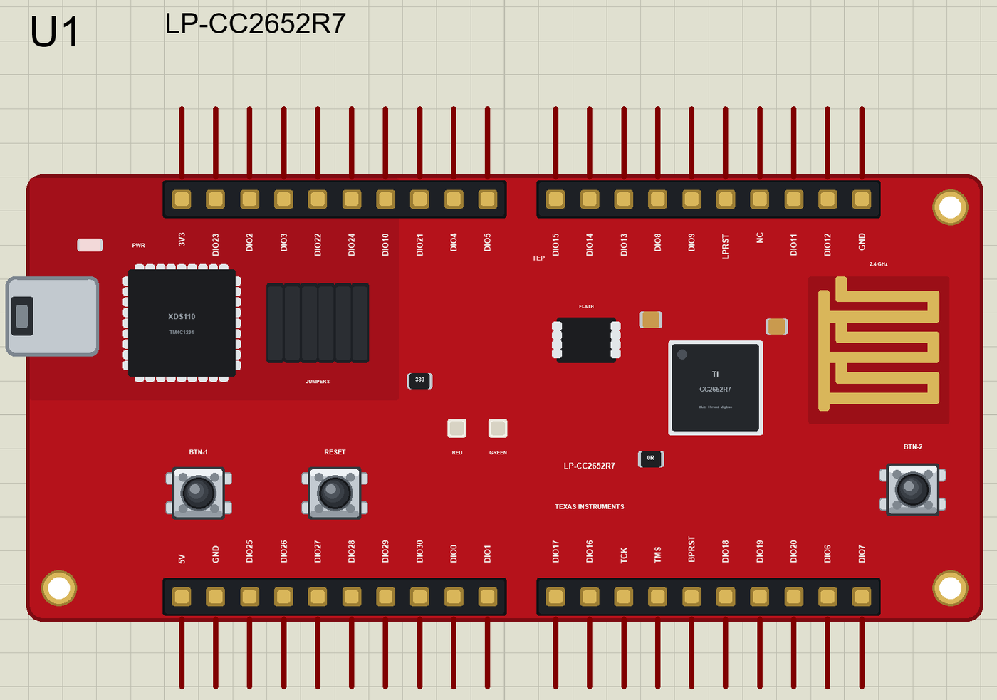
The Pins
| BoosterPack | The pins (from TI's board file) |
|---|---|
| J1, pins 1 to 10 | 3V3, DIO23, DIO2 (RX), DIO3 (TX), DIO22, DIO24, DIO10 (SCK), DIO21, DIO4 (SCL), DIO5 (SDA) |
| J2, pins 11 to 20 | DIO15, DIO14 (BTN2), DIO13 (BTN1), DIO8 (MISO), DIO9 (MOSI), LPRST, NC, DIO11 (CS), DIO12, GND |
| J3, pins 21 to 30 | 5V, GND, DIO25 to DIO30, DIO0, DIO1 |
| J4, pins 31 to 40 | DIO17, DIO16, TCK, TMS, BPRST, DIO18, DIO19, DIO20, DIO6 (LED_RED), DIO7 (LED_GREEN) |
Every DIO is a GPIO with PWM and interrupts; DIO23 to DIO30 are also the analog inputs A0 to A7.
Download LP-CC2652R7 Library for Proteus
Click the button below to download LP-CC2652R7-Library-for-Proteus-v1.0.zip (about 3.3 MB, without the source code of the models):
LP-CC2652R7 Library for Proteus V1.0- README.txt: installation, the demo, the pins, the properties, troubleshooting and the limits.
- Proteus Library Files:
TEPLP2652.LIBand the phone and laptop:TEPMOBILE.LIBandTEPLAPTOP.LIB. - Proteus Model Files:
TEPNET.DLL. - Arduino Code: the demo sketch and the TEP Boards for Proteus add-on 1.76.0, with ArduinoBLE.
- Proteus Simulation: the demo project, its HEX file and a copy of the DLL.
No Proteus yet? Read How to Download and Install Proteus 7 and 8. New to libraries? Follow How to Install a New Library in Proteus.
How to Install LP-CC2652R7 Library for Proteus
- Close Proteus and extract the whole zip file, for example to your Desktop.
- Copy the files from Proteus Library Files into the LIBRARY folder of Proteus.
- Copy
TEPNET.DLLfrom Proteus Model Files into the MODELS folder, replacing an older one. - Delete
TEPLP2652.IDXfrom the LIBRARY folder if it is there. - For your own sketches, copy Arduino Code\TEP Boards for Proteus\hardware into your Arduino sketchbook (Documents\Arduino) and restart the Arduino IDE; the board is TI LP-CC2652R7 LaunchPad (TEP Proteus).
- Start Proteus, press P and search for CC2652.
Demo: a Bluetooth Nurse Call in Simulation
In a hospital every second counts, and a nurse looking after many rooms cannot watch every door. A nurse call button that reaches the nurse's phone, shows which room is calling and remembers how long the patient waited is a small device with a big effect - and a typical Bluetooth LE product.
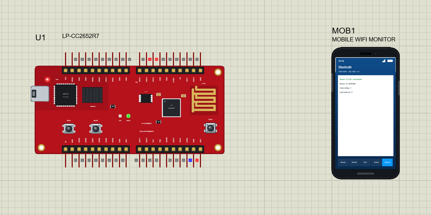
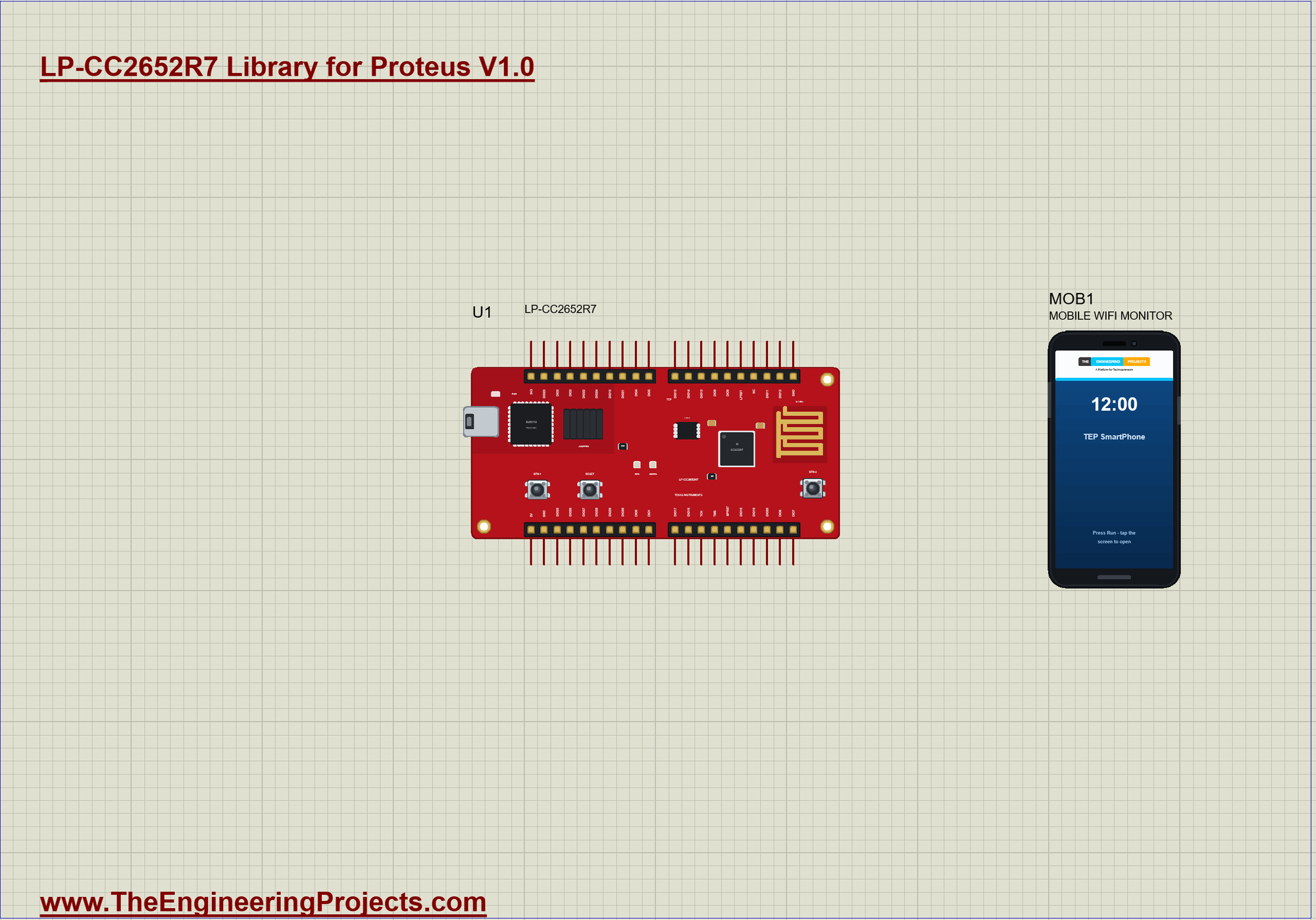
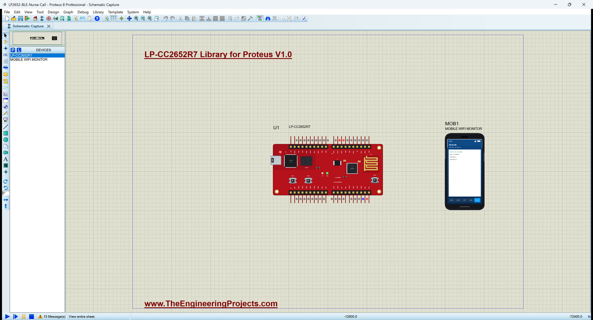
Open LP2652-BLE-Nurse-Call.pdsprj. U1 runs LP2652_Nurse_Call.hex, and MOB1 is the nurse's phone - our Mobile WiFi Monitor - whose Bluetooth app connects to the board. There are no wires on this sheet. The serial monitor is the same window as our TEP Serial Monitor Advance for Proteus.
| Button | State | LED | The phone shows |
|---|---|---|---|
| BTN-1 | CALL | red | CALL, the number of calls |
| BTN-2 (during a call) | NURSE | green | NURSE, the waiting time |
| BTN-2 again | READY | off | READY |
The Patient Calls
patientCalls() starts a call only when the room is ready, counts it, notes the time and tells the phone:
void patientCalls() {
  if (state != READY) return;                               // already calling, or the nurse is here
  calls++;
  callAt = millis();
  remindAt = callAt + REMIND_MS;
  setState(CALLING);
  callsChar.writeValue(calls);
  Serial.print(F(">> Room 12: CALL (call ")); Serial.print(calls); Serial.println(F(" today)"));
}
The Nurse Arrives
BTN-2 has two jobs: during a call it records the waiting time and lights the green LED; when the nurse leaves, it makes the room ready again:
void nurseButton() {
  if (state == CALLING) {
    const int waited = (int)((millis() - callAt + 500) / 1000);
    setState(NURSE);
    waitChar.writeValue(waited);
    Serial.print(F(">> Nurse in room 12 - answered in ")); Serial.print(waited); Serial.println(F(" s"));
  } else if (state == NURSE) {
    setState(READY);
    Serial.println(F(">> Room 12 ready"));
  }
}
One Place for the LEDs
setState() keeps the LEDs and the phone in step with the state, so they can never disagree:
void setState(byte s) {
  state = s;
  digitalWrite(LED_RED, s == CALLING ? HIGH : LOW);
  digitalWrite(LED_GREEN, s == NURSE ? HIGH : LOW);
  statusChar.writeValue(STATE_NAME[s]);
}
A Small State Machine
The whole demo is a state machine with three states: READY, CALL and NURSE. Each button press is an event, and what it does depends on the state: BTN-1 only starts a call when the room is ready, BTN-2 means "I am here" during a call and "I am leaving" after it. Writing it this way keeps the behaviour clear and makes it easy to add a fourth state later, for example an emergency that only a nurse can clear.
Reading the Buttons
readButtons() compares each button with its last value and acts only on the change to LOW. Holding a button down therefore counts once, and a patient who keeps the button pressed does not start a flood of calls.
The Reminder
A call left unanswered is reported again every 20 seconds, so it cannot be forgotten:
void remind() {
  if (state != CALLING || millis() < remindAt) return;
  remindAt += REMIND_MS;
  Serial.print(F("!! Room 12 still waiting: ")); Serial.print((millis() - callAt) / 1000); Serial.println(F(" s"));
}
The Bluetooth Service
The service holds the status, the number of calls and the last waiting time, each with BLERead | BLENotify:
BLEService callService("19B10090-E8F2-537E-4F6C-D104768A1214");
BLEStringCharacteristic statusChar("19B10091-E8F2-537E-4F6C-D104768A1214", BLERead | BLENotify, 12);
BLEIntCharacteristic callsChar("19B10092-E8F2-537E-4F6C-D104768A1214", BLERead | BLENotify);
BLEIntCharacteristic waitChar("19B10093-E8F2-537E-4F6C-D104768A1214", BLERead | BLENotify);
Run the Simulation
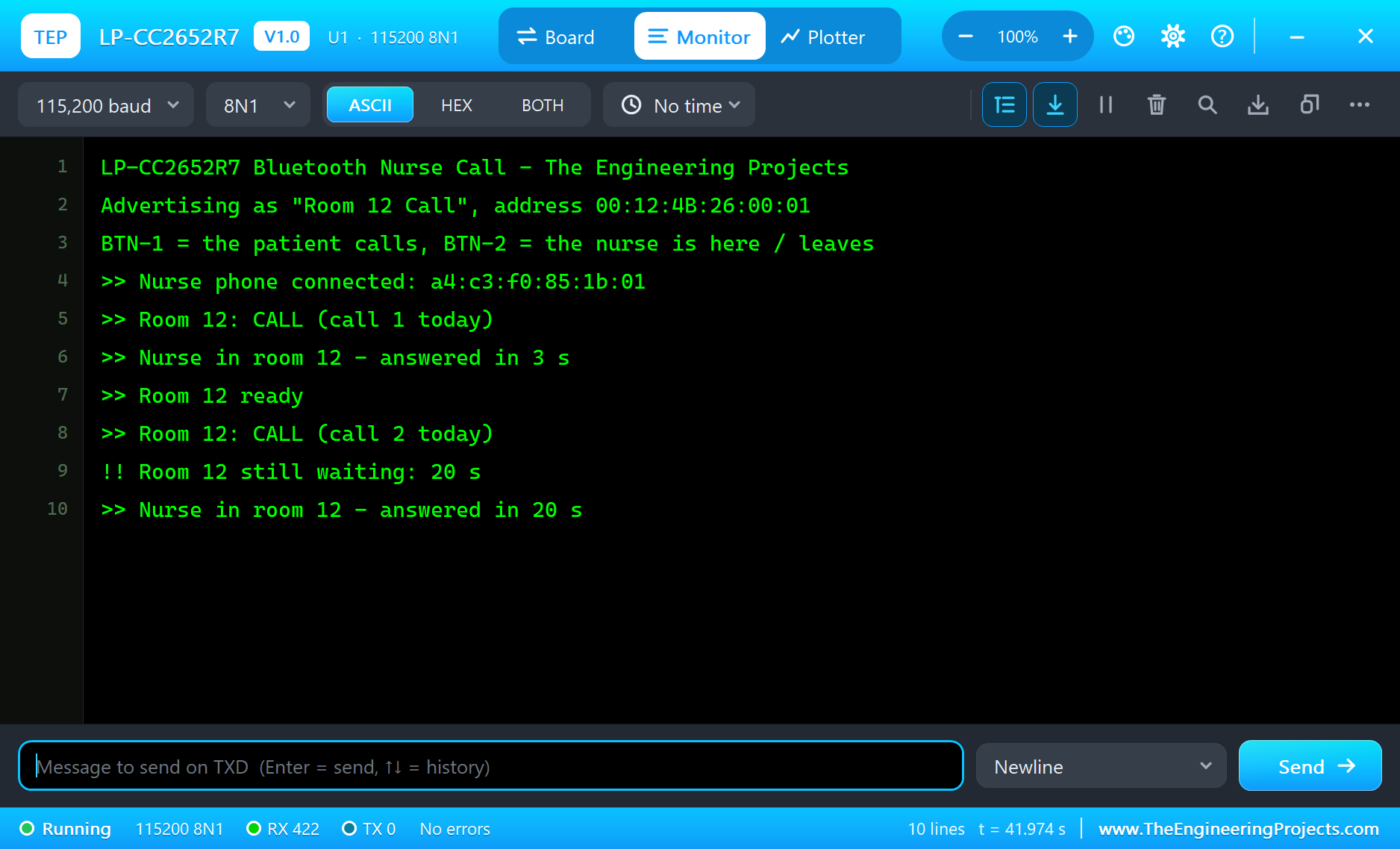
Press Run. The board starts advertising as "Room 12 Call":
LP-CC2652R7 Bluetooth Nurse Call - The Engineering Projects
Advertising as "Room 12 Call", address 00:12:4B:26:00:01
BTN-1 = the patient calls, BTN-2 = the nurse is here / leaves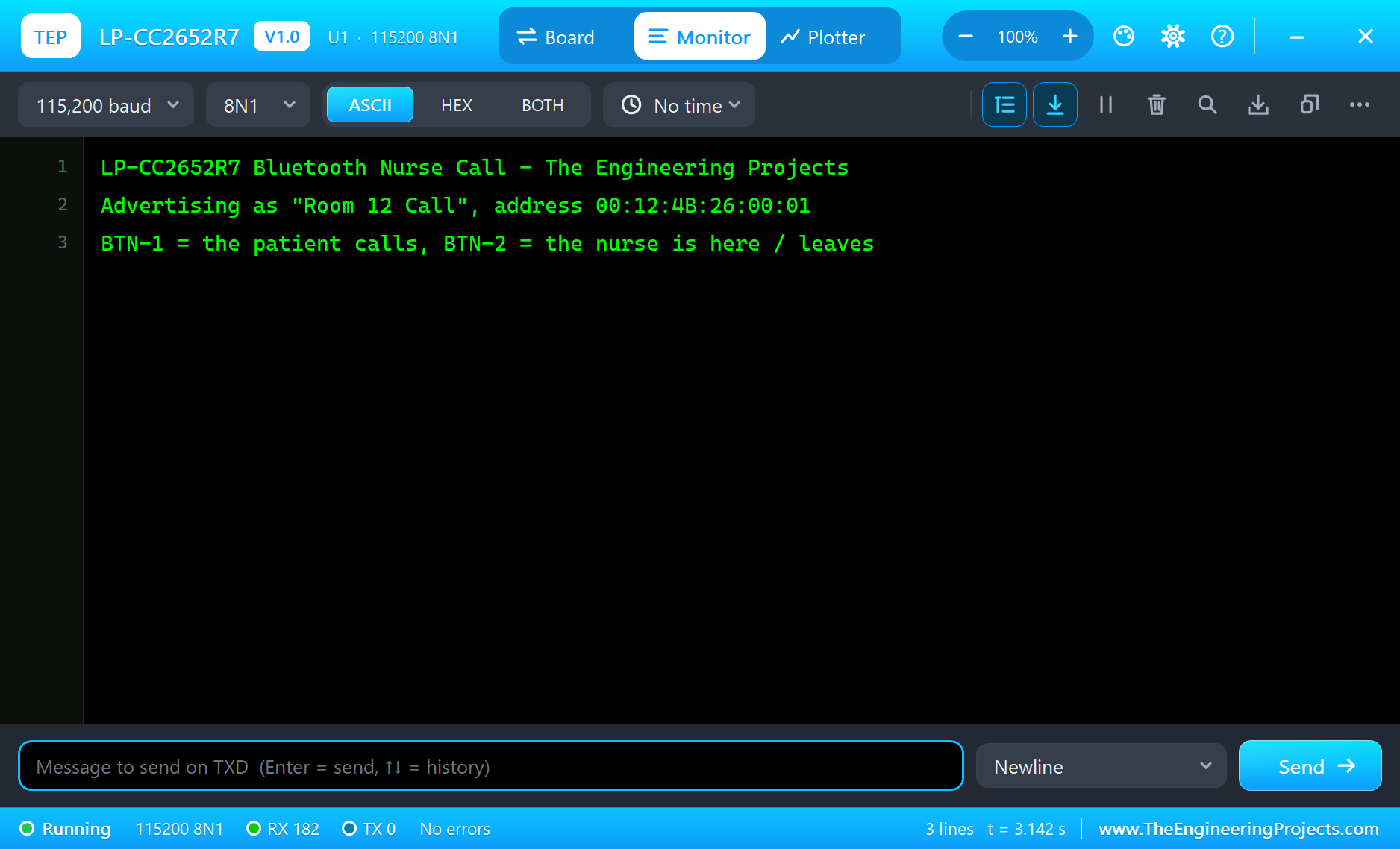
Connect the Nurse's Phone
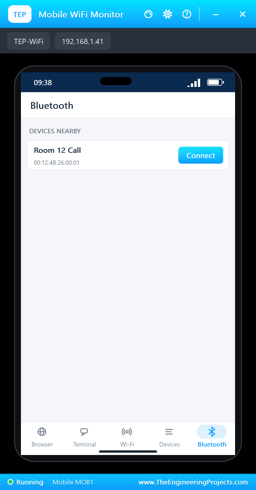
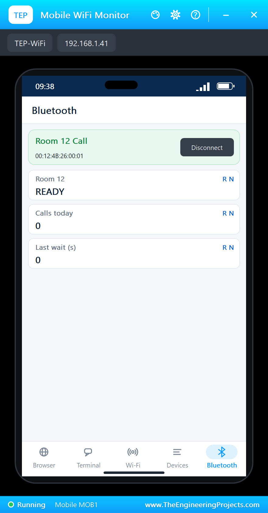
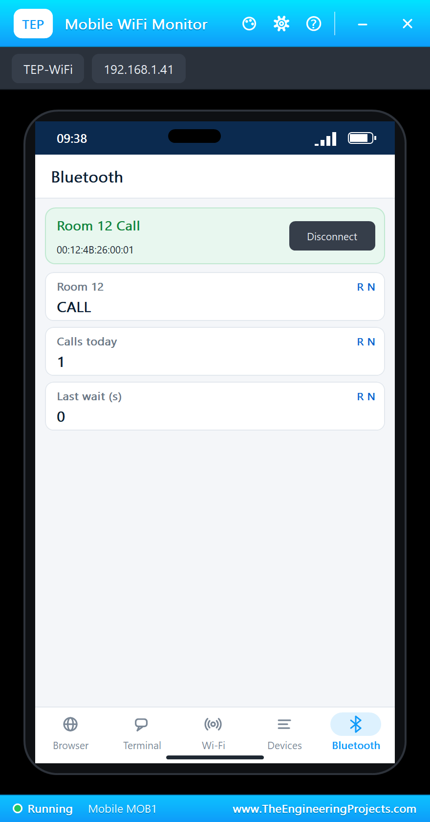
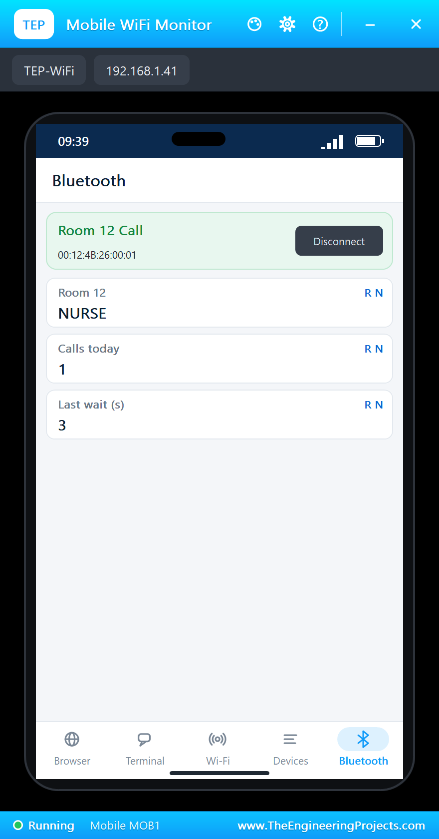
Click the phone, open its Bluetooth app, press SCAN and then Connect to "Room 12 Call":
A Call
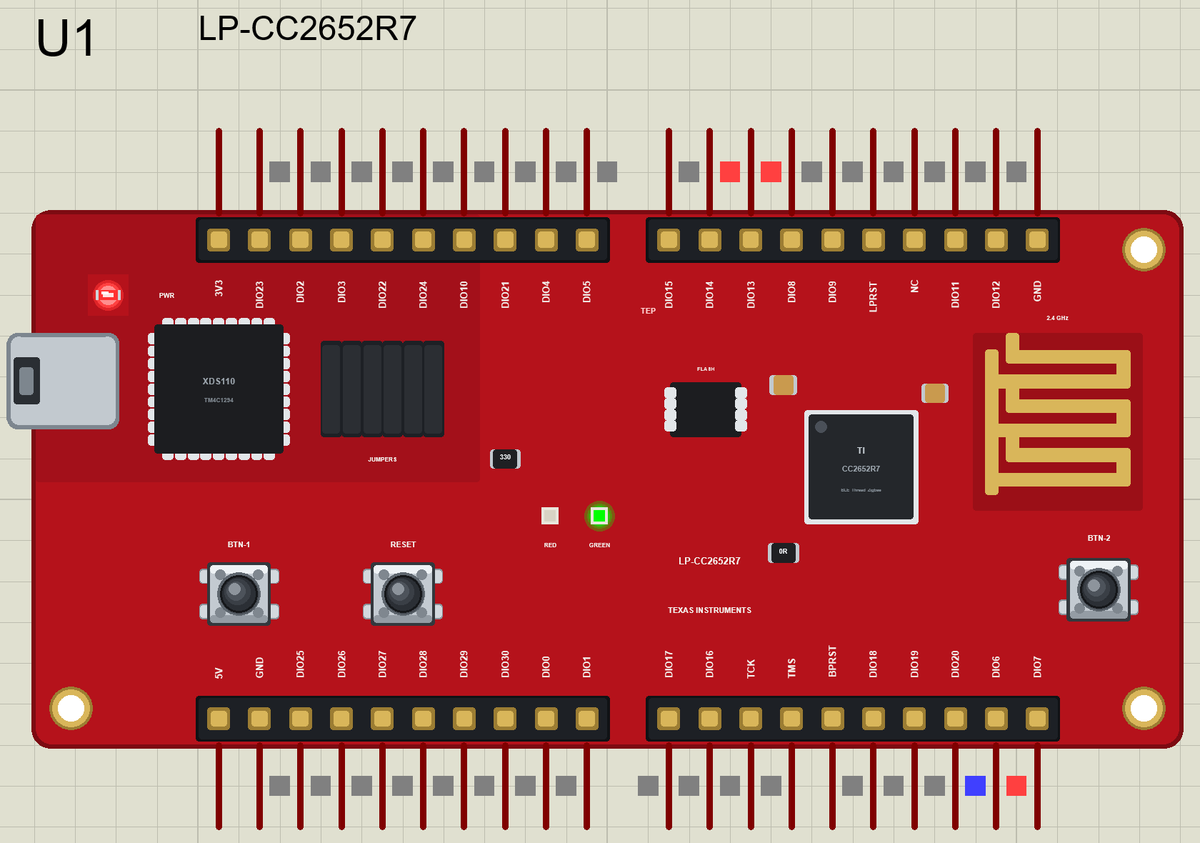
Click BTN-1: the red LED lights and the phone shows CALL. Then click BTN-2: the nurse is in the room, the green LED lights and the waiting time is recorded:
>> Nurse phone connected: a4:c3:f0:85:1b:01
>> Room 12: CALL (call 1 today)
>> Nurse in room 12 - answered in 3 s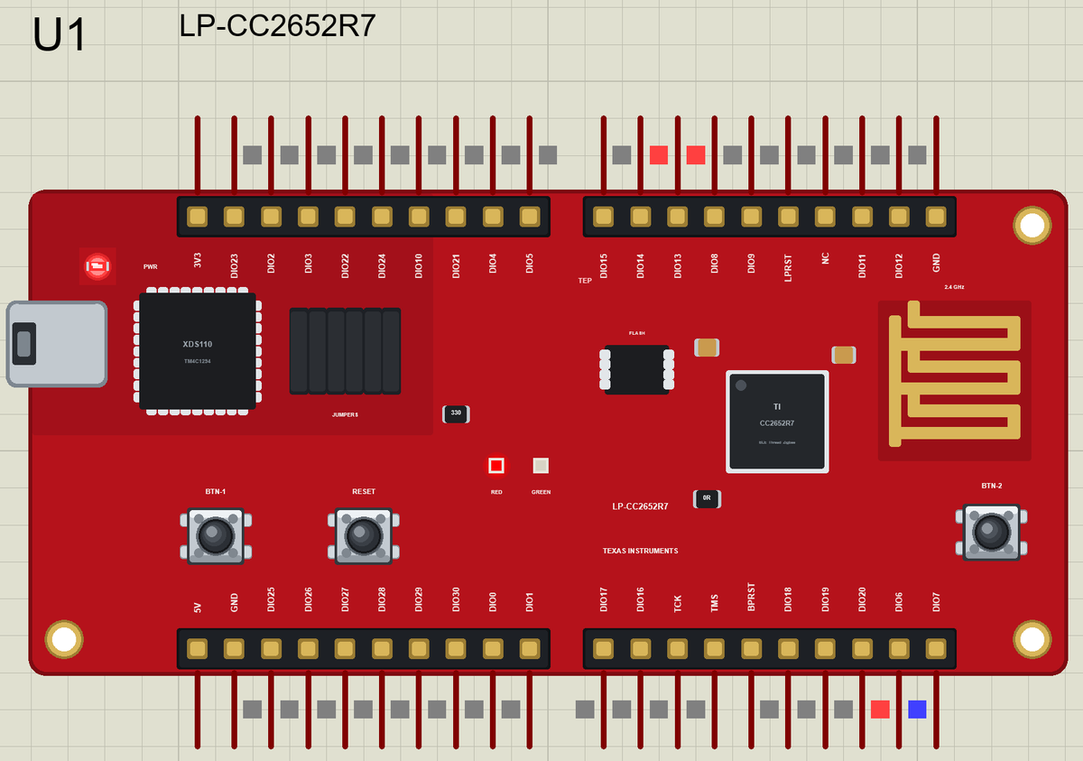
Here is the complete circuit while the simulation runs:
A Call Nobody Answers
BTN-2 again makes the room ready. Click BTN-1 a second time and wait: after 20 seconds the board reports the call again. When the nurse finally clicks BTN-2, the longer waiting time reaches the phone:
>> Room 12 ready
>> Room 12: CALL (call 2 today)
!! Room 12 still waiting: 20 s
>> Nurse in room 12 - answered in 20 s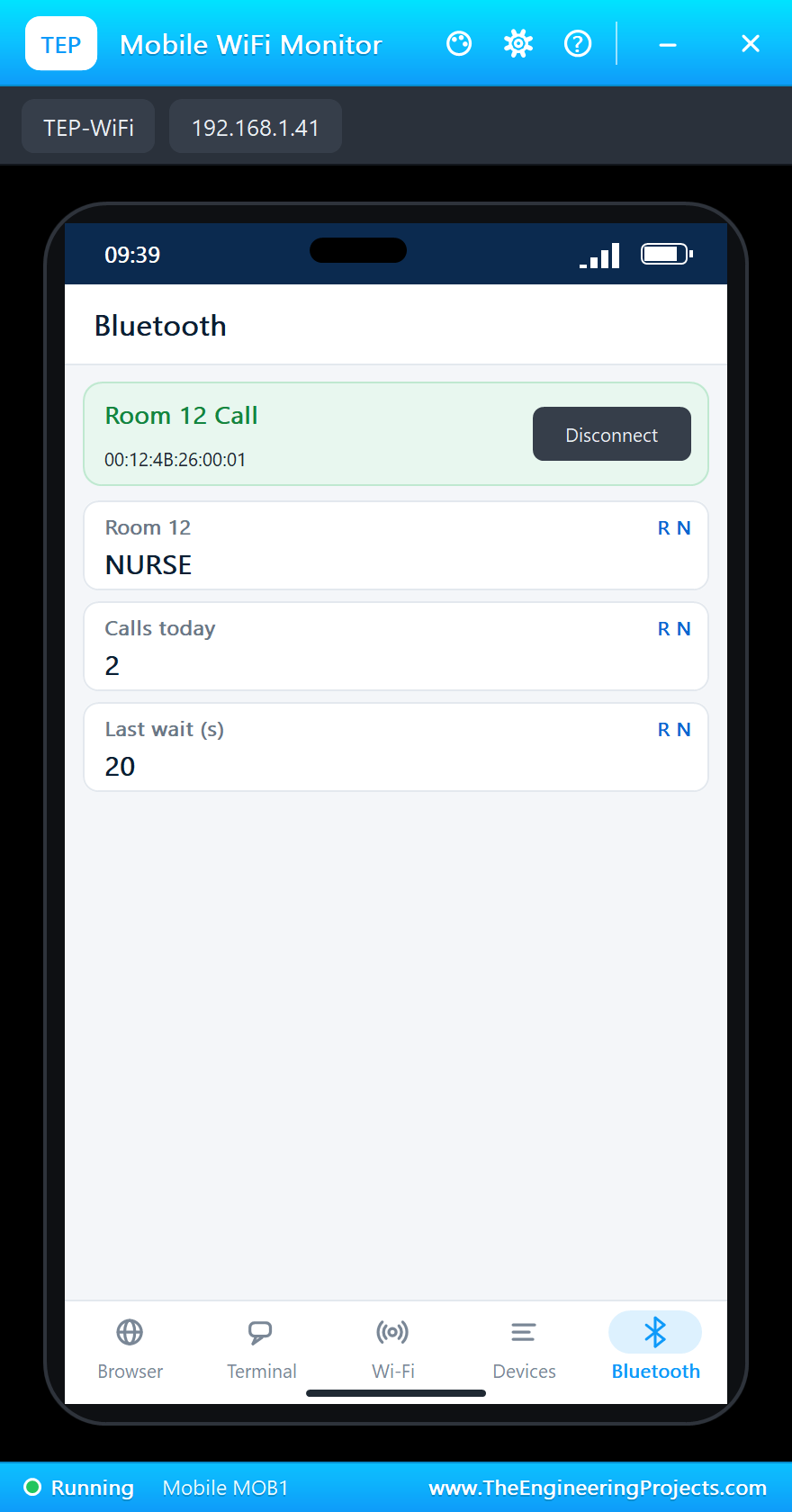
Why Notifications?
The phone could ask the board for the status every second, but that wastes energy on both sides. With notifications the phone subscribes once, and the board sends a value only when it changes - a call, the nurse, ready. For a battery-powered call button that is the difference between weeks and years on one coin cell.
Why Bluetooth LE for a Call Button?
A call button must work for years, cost little and be easy to place anywhere in a room. Bluetooth LE needs no network installation and no cables, and a phone or a small gateway at the nurses' station can receive it. With the CC2652R7 the same button could later join a Thread or Zigbee mesh that covers the whole ward, without changing the hardware.
What the Waiting Time Tells
The waiting time is more than a number on the phone. Collected over a day, it shows when the ward is short of staff and which rooms wait longest. Because the board measures it itself, from the press of BTN-1 to the press of BTN-2, the value is the same whatever the phone is doing, and it stays correct even if the phone was out of range for a moment.
Try It Yourself
- Change
REMIND_MSto 10000 for a faster reminder. - Blink the red LED while a call waits longer than the reminder time.
- Add a writable characteristic so the nurse can acknowledge the call from the phone.
- Count the calls per hour and send the average waiting time.
Testing Every Path
The run above goes through every path of the state machine: a call answered quickly, the room made ready, and a call left waiting until the reminder fires. Trying each path in the simulation is far easier than waiting next to a real board, and it shows mistakes - like a button that does nothing in one state - before the device is installed.
Ideas to Extend the Nurse Call
- Add a buzzer on a free DIO that beeps until the nurse arrives.
- Give each room its own board and name, and let the phone list them all.
- Add an emergency button on DIO15 that is never reset by BTN-2.
- Keep the day's calls in the SPI flash.
Your Own Sketches
Write the sketch in the Arduino IDE with the board TI LP-CC2652R7 LaunchPad (TEP Proteus), use Sketch > Export Compiled Binary and set the part's PROGRAM property to the .hex. Use the DIO numbers printed on the board.
Moving to a Real LP-CC2652R7
- Install Code Composer Studio and TI's SimpleLink Low Power F2 SDK.
- Start from the SDK's simple peripheral example for the LP_CC2652R7 board.
- Add a GATT service with the status, calls and waiting-time characteristics, as in the sketch.
- Read BTN-1 and BTN-2 and drive the LEDs through the SDK's GPIO driver; TI's board file names them BTN-1, BTN-2, LED_RED and LED_GREEN.
- Flash the LaunchPad through the XDS110 and connect with TI's SimpleLink starter app or any Bluetooth app.
The logic of the sketch - the states, the timing and the service - moves across almost line by line.
Things to Know Before Using a Real LP-CC2652R7
- The jumpers: keep the jumper block closed to program and power the chip from the XDS110.
- 3.3 V logic: the BoosterPack pins are 3.3 V; check a 5 V BoosterPack before you plug it in.
- The antenna: keep metal and fingers away from the PCB antenna at the end of the board.
- Over-the-air updates: the SPI flash holds a new image, so a product can be updated from a phone.
Properties of the LP-CC2652R7
| Property | What it does |
|---|---|
| PROGRAM | the sketch: a .hex from TEP Boards for Proteus (board "TI LP-CC2652R7 LaunchPad") |
| MONITOR, BAUD, AUTOOPEN | the built-in serial monitor: on, its baud rate (115200), open at Run |
Troubleshooting
- The phone finds nothing: press SCAN after "Advertising as" is printed; the sketch must call
BLE.advertise(). - A button seems dead: use
INPUT_PULLUPand act on the change to LOW. - An LED stays dark: LED_RED is DIO6 and LED_GREEN DIO7, lit when HIGH.
- A number goes wrong above 32767: int is 16 bits in the simulation - use long.
Limitations of the Simulation
- Bluetooth LE works as a peripheral only. Thread, Zigbee and the sensor controller are not modelled.
- TCK, TMS, BPRST and NC are drawn, not modelled; DIO2 / DIO3 are Serial1 in the simulation.
- Your sketch gets 8 KB of RAM in the simulation, and int is 16 bits there.
- TI, LaunchPad, SimpleLink and BoosterPack are names of Texas Instruments and Arduino of Arduino, and the Bluetooth word mark belongs to Bluetooth SIG; this library is not made or endorsed by them or by Labcenter.
- Tested in Proteus 8.5 in November 2026 (the demo as shipped, about 33 s of simulation). Proteus 7 is not supported.
So, that was all about the LP-CC2652R7 Library for Proteus. I hope it helps you try your Bluetooth ideas on a TI LaunchPad in a simulation before you buy the board - the buttons, the LEDs and the phone, all on one sheet. If you have any questions, ask in the comments and I will help you out. Till the next tutorial, take care and have fun!

Comments
0