


FRDM-MCXN947 Library for Proteus: NXP MCX N947 Tiny AI Simulation


Hello friends, I hope you all are doing great. Today, I am going to share the FRDM-MCXN947 Library for Proteus, so you can run a simulation of NXP's newest FRDM board in Proteus. The FRDM-MCXN947 carries the MCX N947, a microcontroller with two Arm Cortex-M33 cores and a neural processing unit for machine learning, on a black board with an RGB LED, two user buttons, Arduino R3 headers and a mikroBUS socket. With this library it runs your Arduino sketch in Proteus 8.5, and its LED and buttons work with a click.
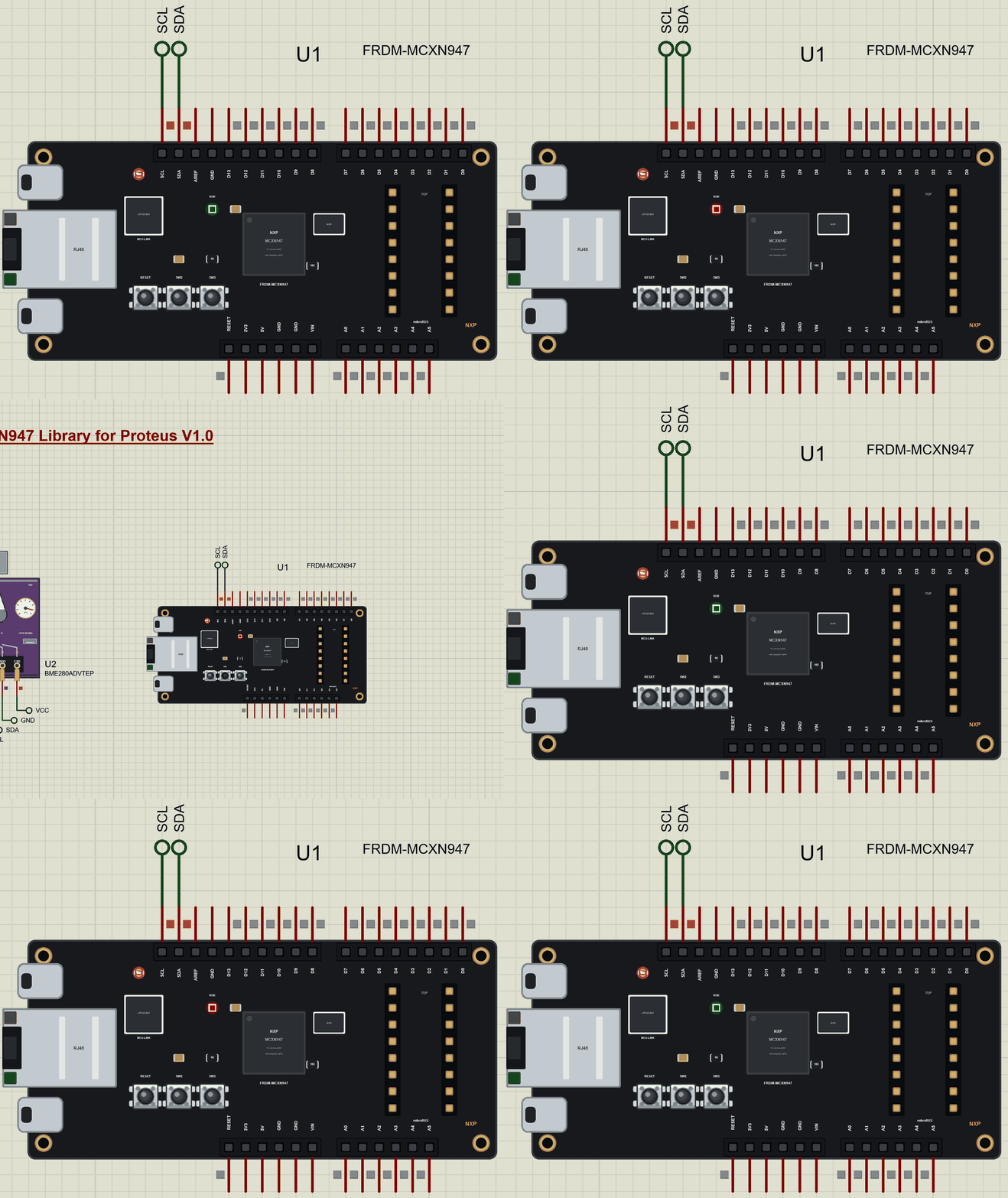
FRDM-MCXN947 Library for Proteus
Latest version: V1.0 (November 2026, this tutorial)
Helping Tools
- Laptop WiFi Monitor: a laptop on the Wi-Fi of your design: a browser, a TCP / UDP terminal and ping
- Mobile WiFi Monitor: a smartphone that opens the pages of your board and sends it commands
- Serial Monitor Advance: a serial terminal window for the UART of your board
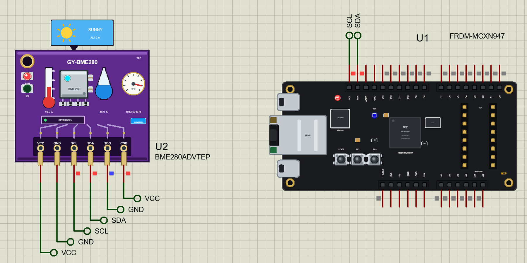
For the demo we built a tiny AI room comfort sensor. A small neural network, trained on a PC and copied into the sketch, reads a BME280 and decides whether the room is COLD, COMFORT or HOT/HUMID - and the RGB LED turns blue, green or red. No cloud, no thresholds written by hand: the network learned them.
NOTICE: Proteus has no MCX N947 model, so our team has put a lot of effort into building this board ourselves: the headers, the RGB LED and the buttons are all our own model, and your sketch compiles with our free TEP Boards for Proteus add-on. Your feedback is the fuel that keeps us going, so please tell us what you think in the comments below. And if our free libraries help you, you can buy us a coffee. So, let's get started with the FRDM-MCXN947 Library for Proteus:
What is the FRDM-MCXN947?
The FRDM-MCXN947 is NXP's low-cost development board for the MCX N94x family. Its MCX N947 has two Arm Cortex-M33 cores at 150 MHz, 2 MB of flash in two banks and 512 KB of RAM, and next to them the eIQ Neutron NPU, a small processor made for neural networks. The board adds the MCU-Link debugger with its USB-C, a high-speed USB-C port, an RJ45 Ethernet jack, QSPI flash, an RGB LED, the buttons SW2 and SW3 and RESET, and four kinds of headers: Arduino R3, mikroBUS, a FlexIO / LCD header and a camera header.
| Part | The real FRDM-MCXN947 | In the library |
|---|---|---|
| MCU | MCX N947: two Cortex-M33 at 150 MHz | your Arduino sketch |
| AI | eIQ Neutron NPU | the demo's network runs in the sketch |
| LED | RGB LED, each colour active LOW | LED_RED, LED_GREEN, LED_BLUE |
| Buttons | SW2, SW3, RESET | SW2, SW3 (LOW when pressed), RESET |
| Headers | Arduino R3, mikroBUS, LCD, camera | the Arduino R3 pins |
| Memory | 2 MB flash, 512 KB RAM | about 256 KB of flash, 8 KB of RAM |
What Is an NPU?
A neural processing unit is a small accelerator for the arithmetic of neural networks: thousands of multiplications and additions of small numbers, done in parallel. A Cortex-M core can run a small network too, but the NPU runs a much larger one in a fraction of the time and the energy. That makes things possible on a battery-powered board that used to need a phone or a PC: recognising a spoken word, a face, a gesture or the sound of a failing machine.
Edge AI
Running the network on the device itself is called edge AI. Nothing leaves the board, so it works without an internet connection, answers in milliseconds and keeps the data private. The usual workflow is the one our demo follows on a small scale: collect examples, train the network on a PC, convert the trained weights for the microcontroller and run it there. NXP's eIQ tools do the conversion for the MCX N94x and place the network on the NPU.
Two Cores
The two Cortex-M33 cores can share the work: one runs the main application, the other handles communication or signal processing. Both have the TrustZone security extension, and the chip adds NXP's EdgeLock secure subsystem for keys and secure boot - important for connected products that must be updated safely in the field.
Where Is It Used?
The MCX N94x family targets smart-home and industrial devices with a little intelligence: appliances that recognise voice commands, sensors that spot anomalies in vibration, simple vision with the camera header, and motor control. Universities use the FRDM boards for courses on embedded machine learning. For other research boards from our series, see the SAM R21 Xplained Pro Library for Proteus with 802.15.4 and the NUCLEO-H743ZI2 Library for Proteus with Ethernet.
A simulation lets you build and test the logic around a model before the board is on the desk: the inputs, the decisions, the LED and the buttons. When the sketch works in the Proteus simulation, the real board only has to confirm it.
Features of the FRDM-MCXN947 Library for Proteus
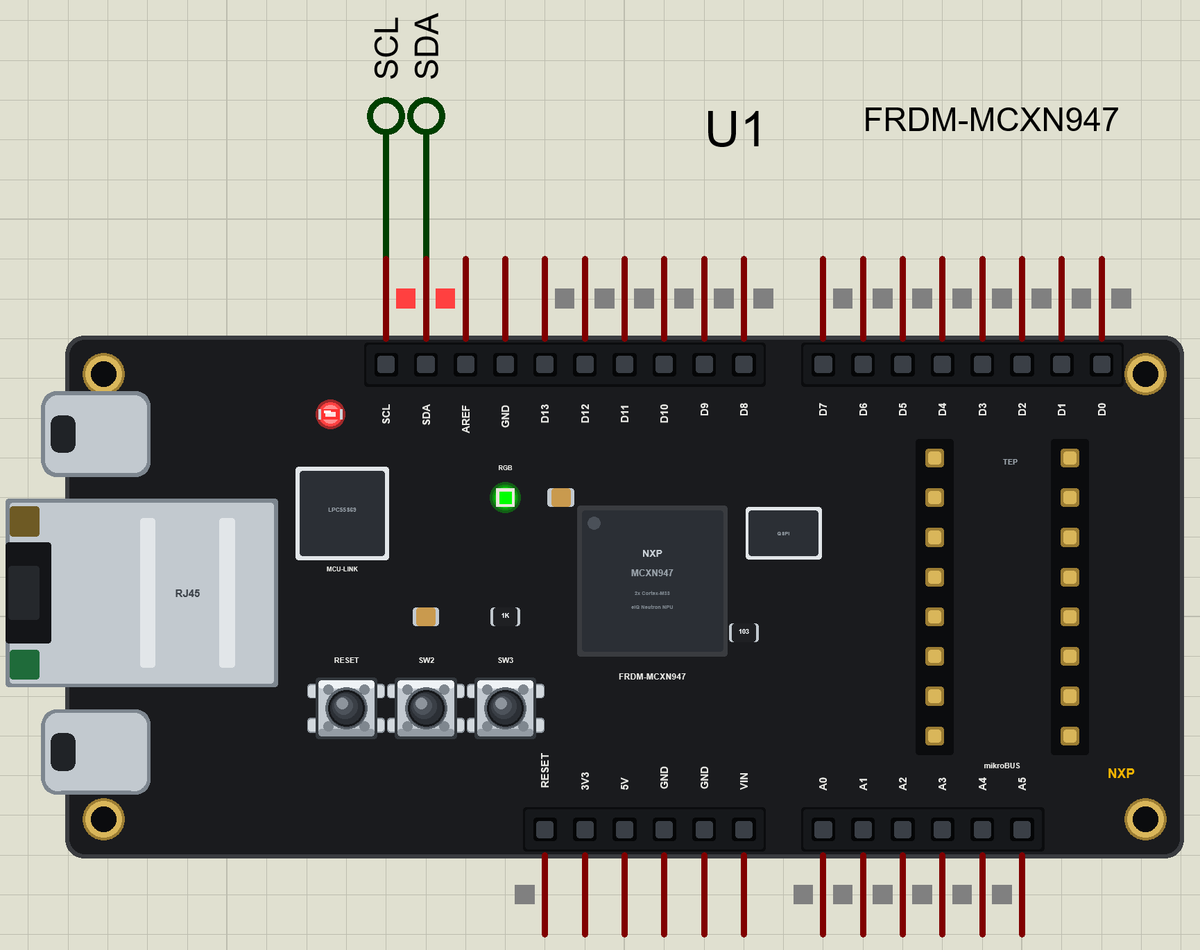
- The board as it looks: the black FRDM PCB with the MCU-Link and its USB-C, the high-speed USB-C, the RJ45 jack, the MCX N947, the QSPI flash, the RGB LED, SW2, SW3, RESET, the Arduino R3 headers and the mikroBUS socket, drawn compact, with our small TEP signature.
- Your sketch: a .hex for "NXP FRDM-MCXN947 (TEP Proteus)" with Arduino R3 names: D0 to D15, A0 to A5, LED_RED, LED_GREEN, LED_BLUE, SW2 and SW3.
- A real RGB LED: each colour lights when its pin is LOW, as on the real board, and the colours mix.
- Two buttons: SW2 and SW3 are clicked on the board.
- A complete package: about 3.8 MB with the part, the add-on, the BME280 and the demo, without the source code of the models.
The FRDM-MCXN947 in Proteus Simulation
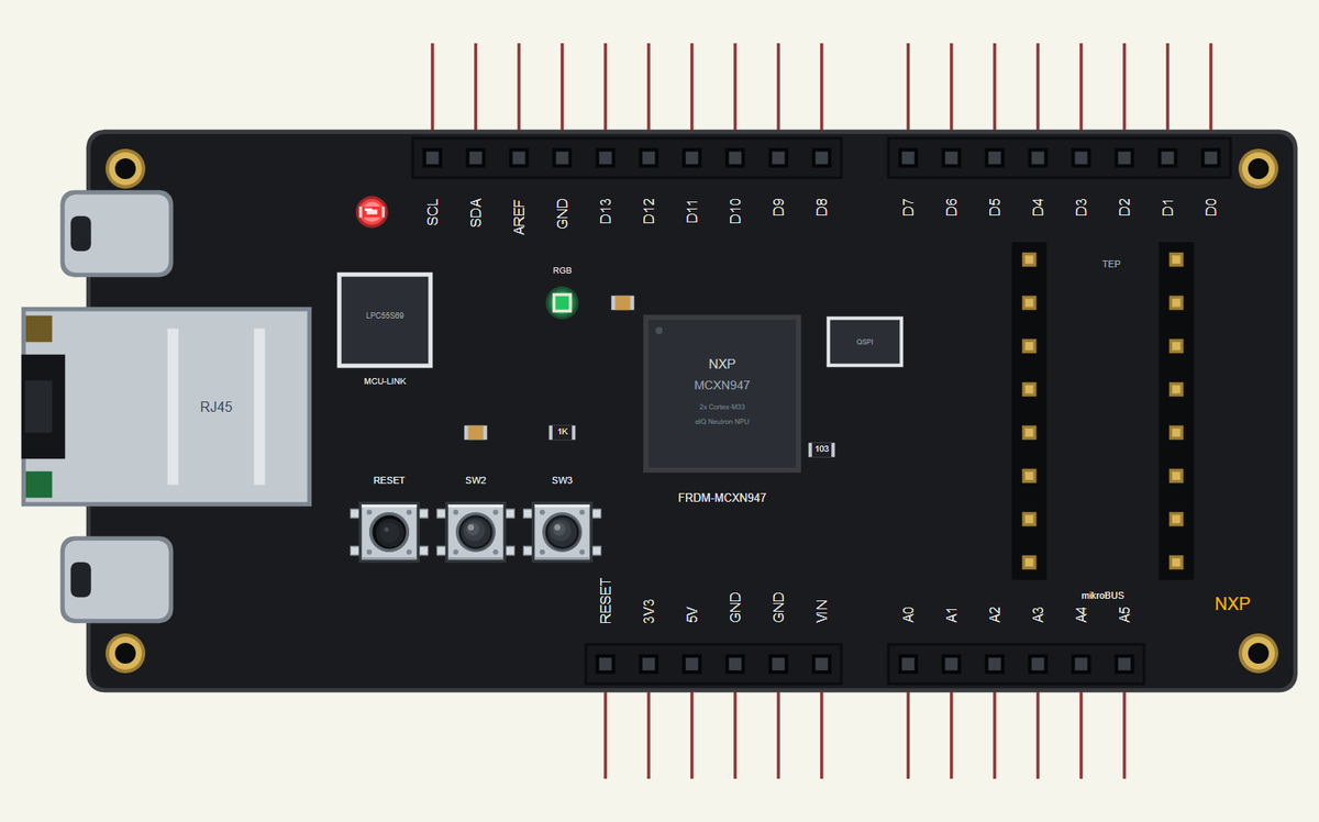
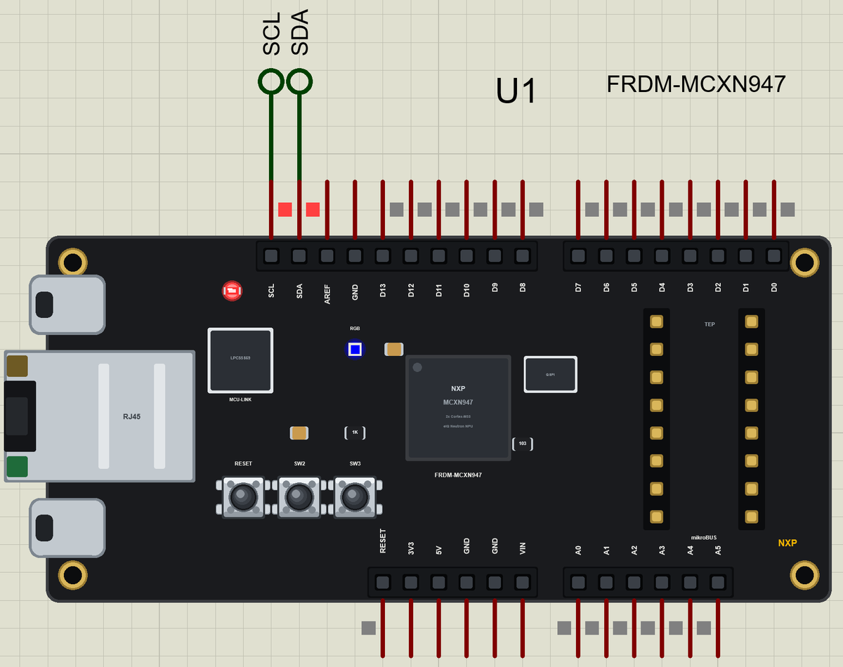
Search FRDM in Pick Devices; the device is in TEPFRDMN947.LIB (Microprocessor ICs, NXP Boards), with the prefix U. The MCU-Link's USB opens the serial monitor.
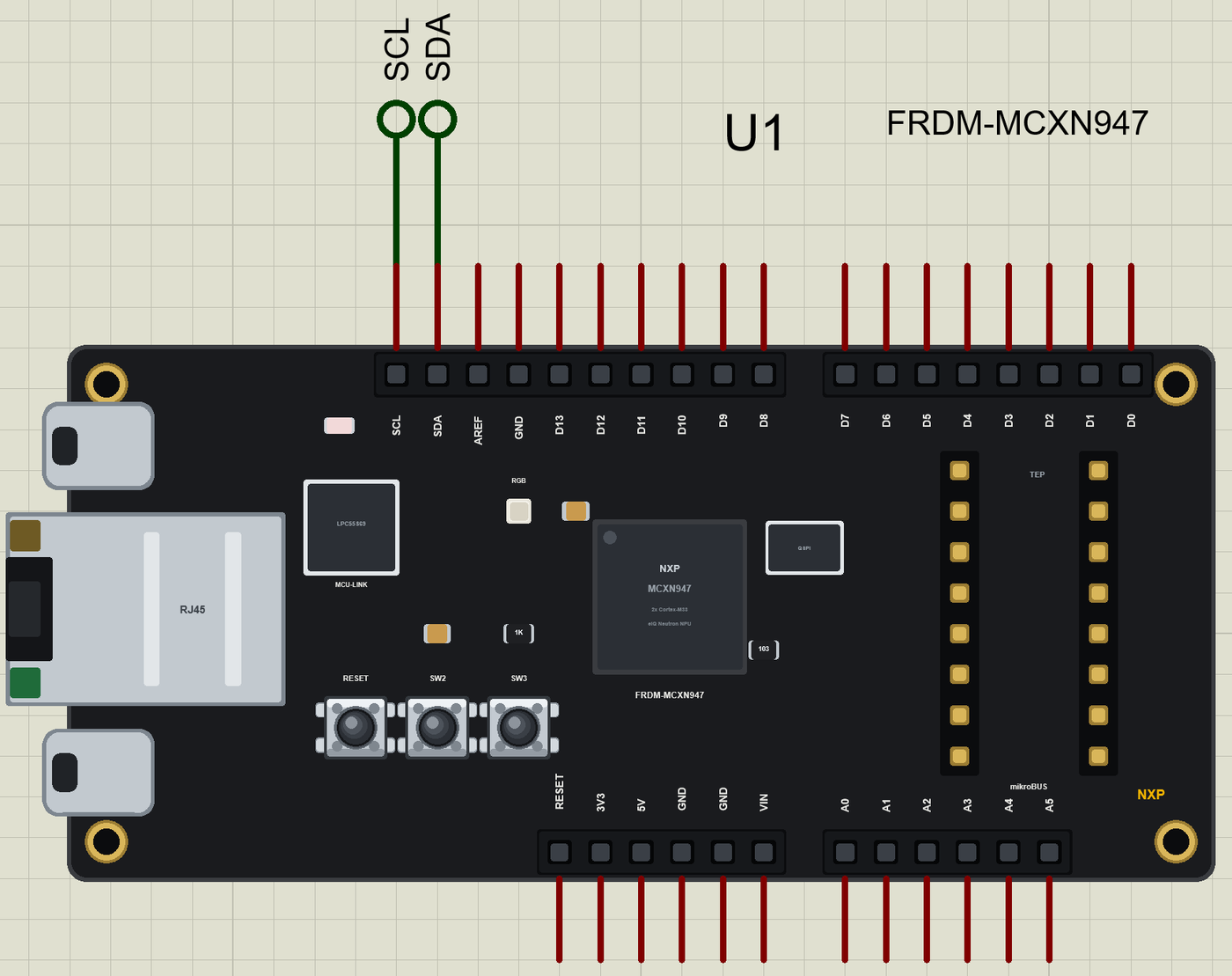
The Pins
| Pins | What the library does with them |
|---|---|
| D0 to D13 | GPIO, PWM with analogWrite, attachInterrupt; D0 / D1 Serial1; D10 to D13 SPI |
| SDA, SCL | D14 and D15: Wire, the I2C bus |
| A0 to A5 | analogRead 0 to 1023 for 0 to 3.3 V, or GPIO |
| LED_RED, LED_GREEN, LED_BLUE | the RGB LED, each colour lit when LOW |
| SW2, SW3 | the buttons, LOW when pressed |
| 3V3, 5V, GND, RESET | the supply and the reset |
NXP makes no Arduino core for this board, so the board package uses the Arduino R3 header's own names, the ones printed next to the header on the real board.
Download FRDM-MCXN947 Library for Proteus
Click the button below to download FRDM-MCXN947-Library-for-Proteus-v1.0.zip (about 3.8 MB, without the source code of the models):
FRDM-MCXN947 Library for Proteus V1.0- README.txt: installation, the demo, the pins, the properties, troubleshooting and the limits.
- Proteus Library Files:
TEPFRDMN947.LIBand the BME280:TEPBME280.LIB. - Proteus Model Files:
TEPNET.DLLandTEPBME280.DLL. - Arduino Code: the demo sketch and the TEP Boards for Proteus add-on 1.74.0.
- Proteus Simulation: the demo project, its HEX file and copies of the DLLs.
No Proteus yet? Read How to Download and Install Proteus 7 and 8. New to libraries? Follow How to Install a New Library in Proteus.
How to Install FRDM-MCXN947 Library for Proteus
- Close Proteus and extract the whole zip file, for example to your Desktop.
- Copy the files from Proteus Library Files into the LIBRARY folder of Proteus.
- Copy the DLLs from Proteus Model Files into the MODELS folder, replacing an older
TEPNET.DLL. - Delete
TEPFRDMN947.IDXfrom the LIBRARY folder if it is there. - For your own sketches, copy Arduino Code\TEP Boards for Proteus\hardware into your Arduino sketchbook (Documents\Arduino) and restart the Arduino IDE; the board is NXP FRDM-MCXN947 (TEP Proteus). The demo also needs Adafruit BME280 and Adafruit Unified Sensor from the Library Manager.
- Start Proteus, press P and search for FRDM.
Demo: a Tiny AI Room Comfort Sensor in Simulation
Is a room comfortable? It depends on the temperature and the humidity together: 25 C is fine in dry air and sticky at 85 %. You could write the rules by hand, but the idea of machine learning is that a network learns them from examples. Our network learned from 6,000 example rooms; it is tiny, but it shows the whole workflow of edge AI on a microcontroller.
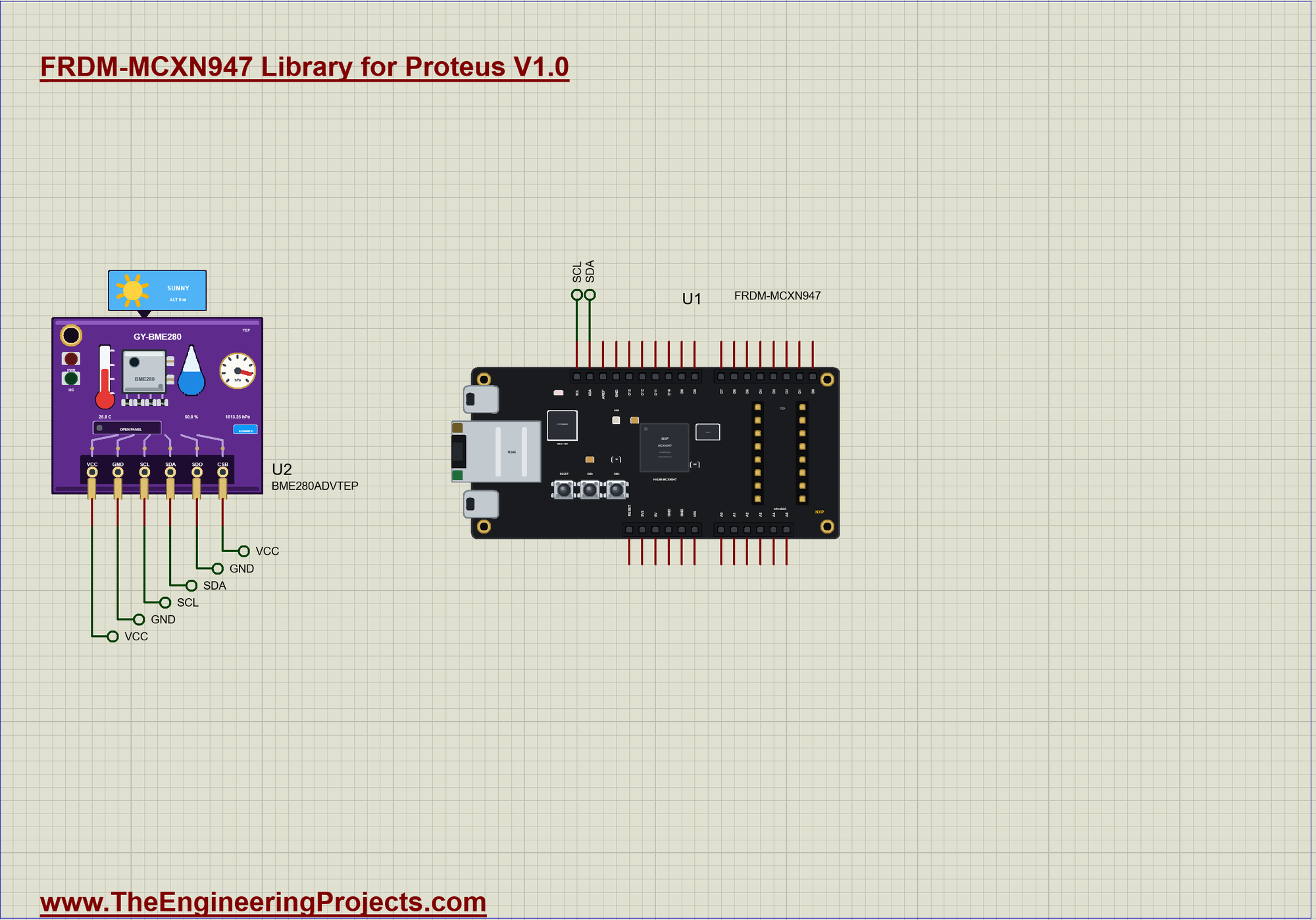
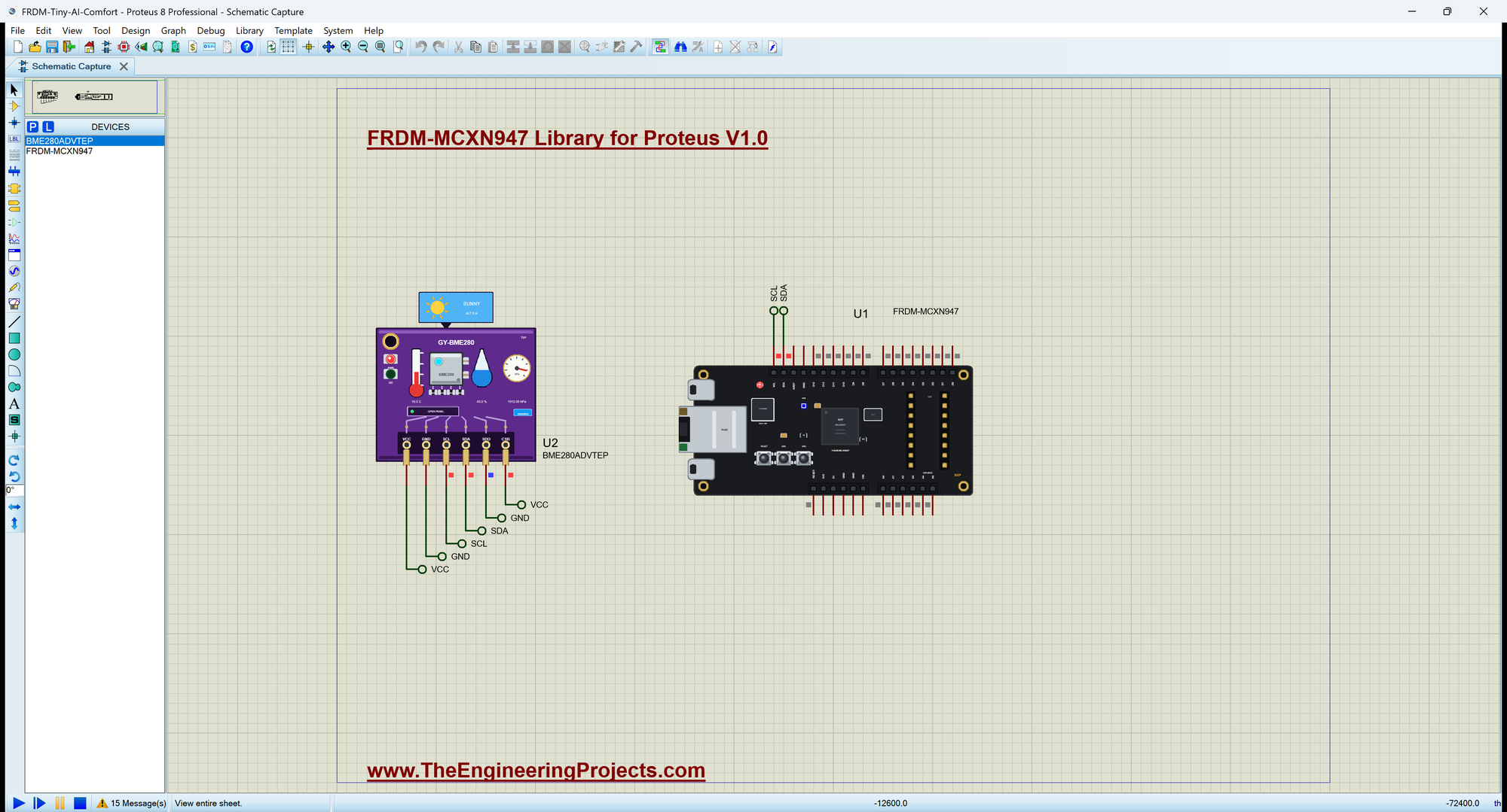
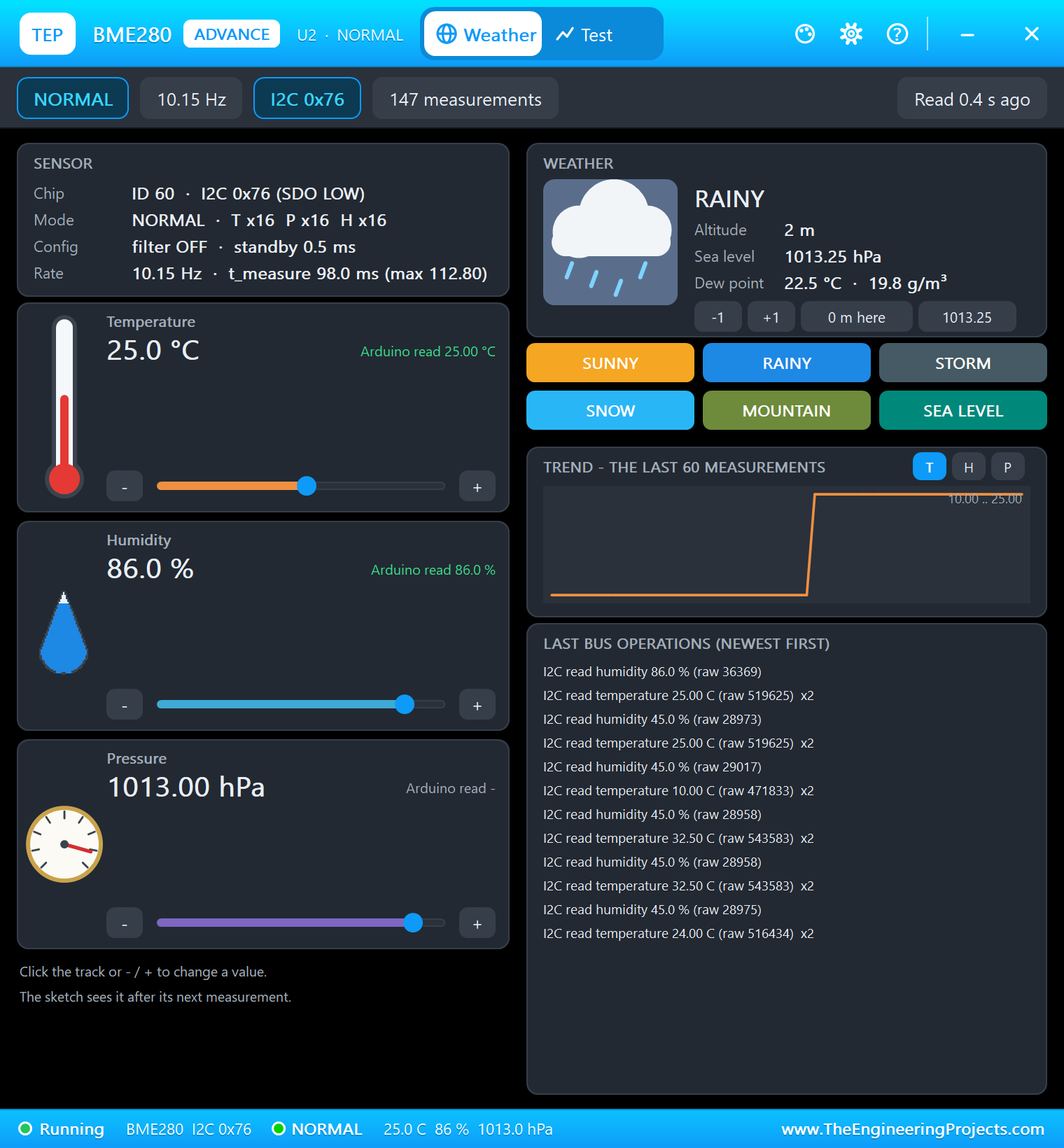
Open FRDM-Tiny-AI-Comfort.pdsprj. U1 runs FRDM_Comfort_AI.hex. U2 is our BME280 (Advance) on SDA and SCL. The serial monitor is the same window as our TEP Serial Monitor Advance for Proteus.
| The network says | When (what it learned) | RGB LED |
|---|---|---|
| COLD | below 18 C | blue |
| COMFORT | 18 C to 28 C and up to 70 % | green |
| HOT/HUMID | above 28 C, or above 70 % | red |
The Trained Network
The network has two inputs, six hidden neurons and three outputs. A short Python script trained it on random rooms labelled by the rules above, and printed the weights as C arrays; they reached 99 % on a fine grid of rooms. Here they are, pasted into the sketch:
const float W_IN[2][6] = {{3.8647, 0.1000, 7.5274, 2.2091, 4.4857, 4.8675}, {-1.4150, 0.2665, 0.0989, -1.1055, 2.4175, -1.8313}};
const float B_HID[6] = {-1.3844, -0.4425, 3.6281, 1.6258, 0.4823, -1.7227};
const float W_OUT[6][3] = {{0.7599, -2.3618, 3.7450}, {-1.0101, 0.0002, -0.5690}, {-6.0257, 5.1985, 2.0212}, {0.7143, 2.4993, -1.7493},
                           {1.2402, -4.3081, 3.2202}, {-0.5555, -4.0979, 3.6133}};
const float B_OUT[3] = {5.6089, -2.6045, -3.0044};
How the Network Was Trained
The training script makes 6,000 random rooms between 0 and 45 C and between 10 and 95 % humidity, and labels each one with the rule. It starts with random weights and repeats one step 6,000 times: run the network on all the rooms, measure how wrong the answers are, and nudge every weight a little in the direction that makes them less wrong. This is gradient descent, the same method that trains the large networks of today, only with far fewer numbers. The whole training takes a few seconds on a PC.
Why Not Just Write the Rules?
For two inputs and three classes you could write the rules with a few if statements, and for a real product you might. The network is here to show the method. Its strength appears when the rules are unknown or too complex to write: the sound of a worn bearing, a gesture in accelerometer data or a face in a camera image. Then you collect examples instead of writing rules, and the same train, convert and run steps take you from the PC to the microcontroller.
Inside One Neuron
Each hidden neuron multiplies the two inputs by its two weights, adds its bias, and passes the sum through ReLU: negative sums become zero, positive ones stay as they are. That simple bend is what lets a network learn borders that are not straight lines, like the corner where warm and humid meet. Each output neuron then adds up the six hidden values with its own weights. Altogether the network has only 39 numbers.
Running the Network
infer() is the whole neural network: it scales the inputs, computes the hidden layer with ReLU, the three outputs, and softmax turns them into probabilities. It returns the class with the highest score:
byte infer(float t, float h, float p[3]) {
  const float x0 = (t - 22.0) / 10.0, x1 = (h - 50.0) / 30.0;
  float hidden[6];
  for (byte j = 0; j < 6; j++) hidden[j] = max(0.0f, x0 * W_IN[0][j] + x1 * W_IN[1][j] + B_HID[j]);
  float out[3], top = -1e9;
  byte best = 0;
  for (byte k = 0; k < 3; k++) {
    out[k] = B_OUT[k];
    for (byte j = 0; j < 6; j++) out[k] += hidden[j] * W_OUT[j][k];
    if (out[k] > top) { top = out[k]; best = k; }
  }
  float sum = 0;
  for (byte k = 0; k < 3; k++) { p[k] = exp(out[k] - top); sum += p[k]; }
  for (byte k = 0; k < 3; k++) p[k] /= sum;
  return best;
}
Every 2 seconds readRoom() reads the BME280 and asks the network. Only a change of class is printed:
void readRoom() {
  tempC = bme.readTemperature();
  humidity = bme.readHumidity();
  nextRead = millis() + READ_MS;
  const byte c = infer(tempC, humidity, prob);
  if (c != roomClass) {
    roomClass = c;
    showClass(c);
    Serial.print(F(">> The network says: ")); Serial.print(CLASS_NAME[c]);
    Serial.print(F(" (")); Serial.print((int)(prob[c] * 100 + 0.5)); Serial.print(F(" %)  ")); printRoom(); Serial.println();
  }
}
The RGB LED
Each colour of the RGB LED lights when its pin is LOW, so the sketch drives the winner LOW and the other two HIGH:
void showClass(byte c) {                                    // the RGB LED: each colour lit when LOW
  digitalWrite(LED_BLUE, c == 0 ? LOW : HIGH);
  digitalWrite(LED_GREEN, c == 1 ? LOW : HIGH);
  digitalWrite(LED_RED, c == 2 ? LOW : HIGH);
}
A Self-Test
SW3 runs the network on six known rooms and prints its answers - a quick check that the weights were copied correctly. These are the six rooms:
void selfTest() {
  const float rooms[6][2] = {{24, 45}, {30, 45}, {10, 45}, {25, 85}, {16, 60}, {21, 55}};
  Serial.println(F("Self-test:"));
  for (byte i = 0; i < 6; i++) {
Run the Simulation
Press Run. The room starts at 24 C and 45 %, the network says COMFORT, and the RGB LED is green:
FRDM-MCXN947 Tiny AI Room Comfort - The Engineering Projects
Network: 2 inputs, 6 hidden (ReLU), 3 outputs - SW2 = scores, SW3 = self-test
>> The network says: COMFORT (100 %)  24.0 C  45 %
Room 24.0 C  45 %  COMFORT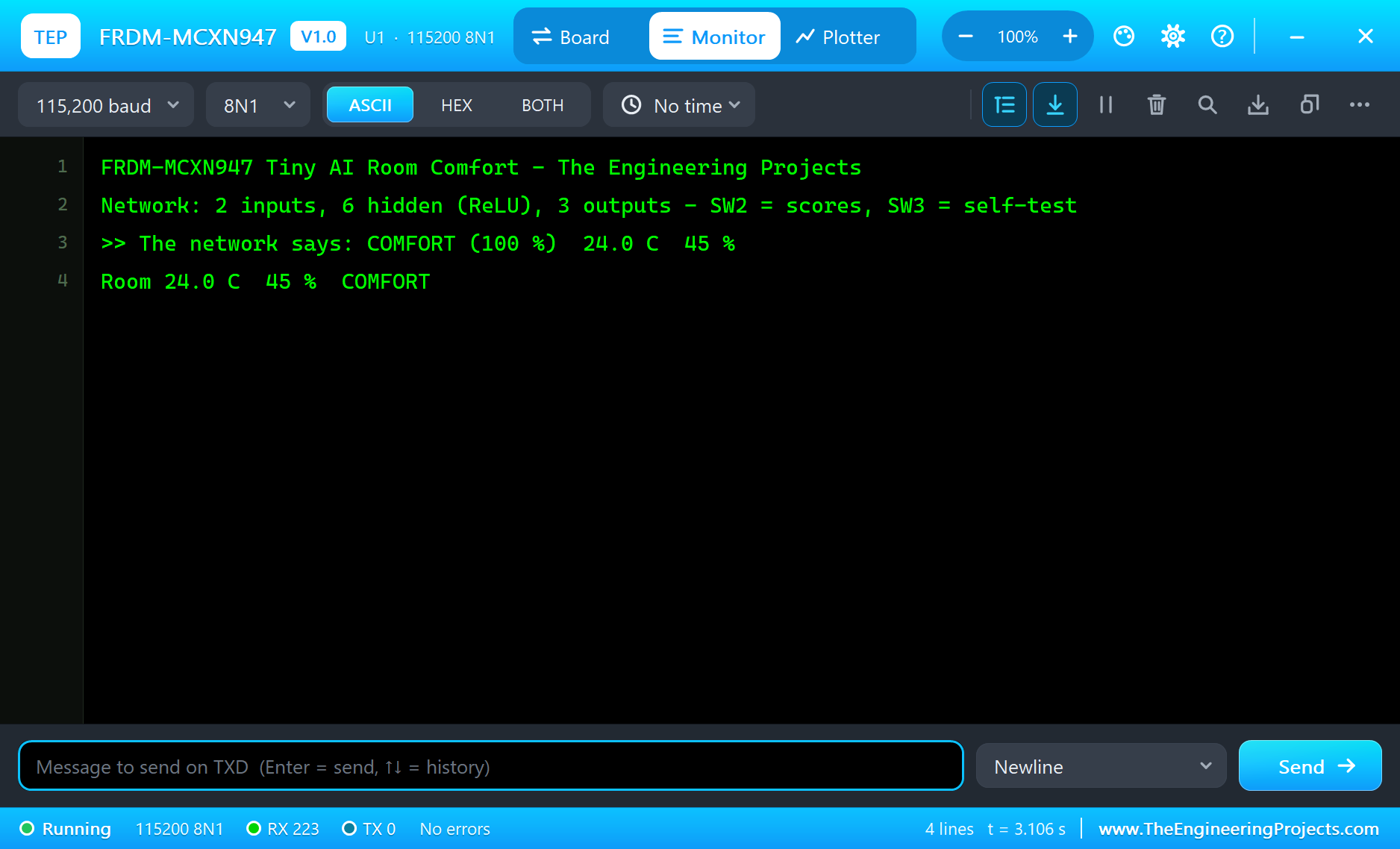
A Hot Room
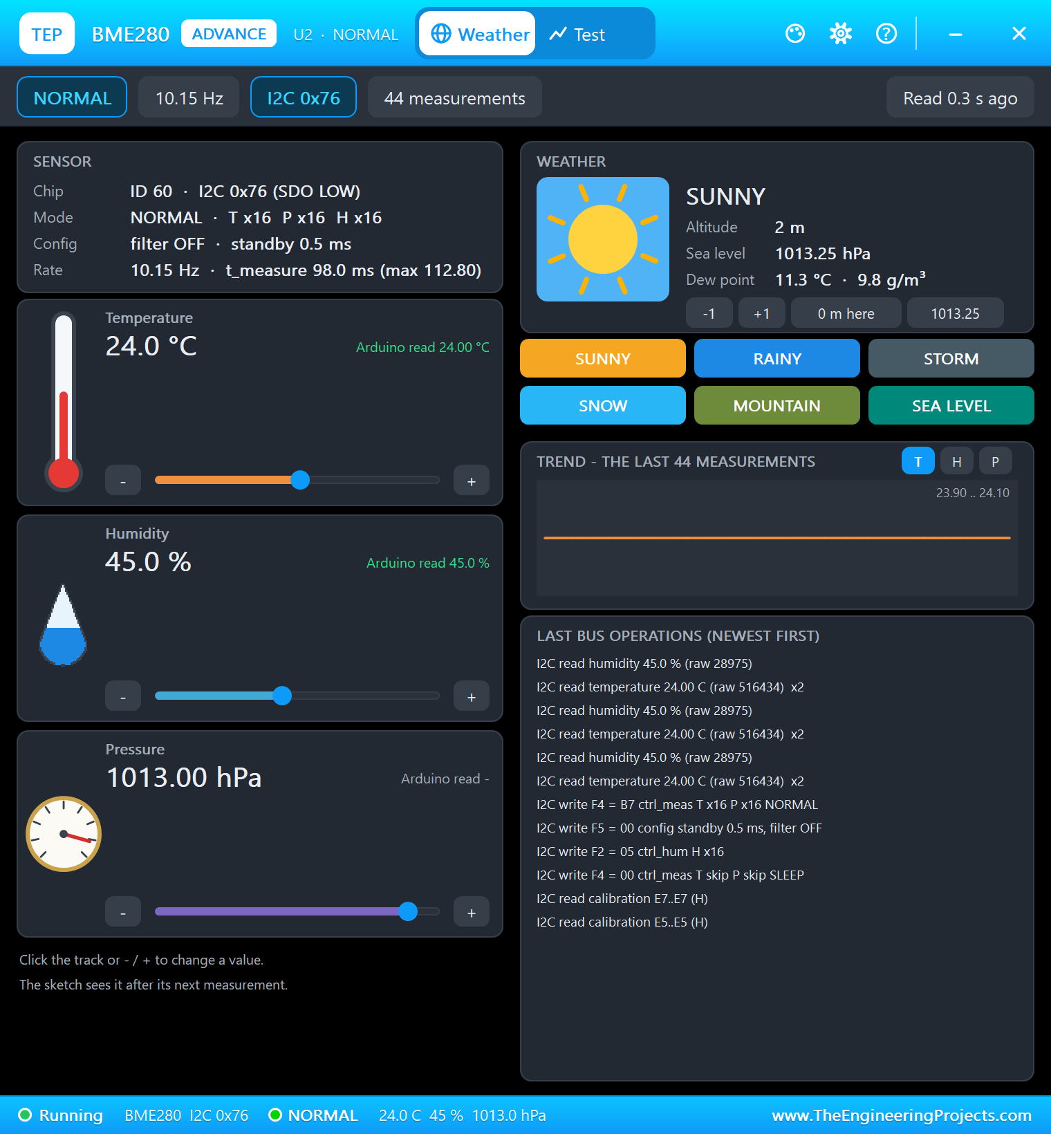
In the BME280's window, click the temperature track at about 32.5 C. The network changes its mind and the LED turns red. Click SW2 to see the three scores:
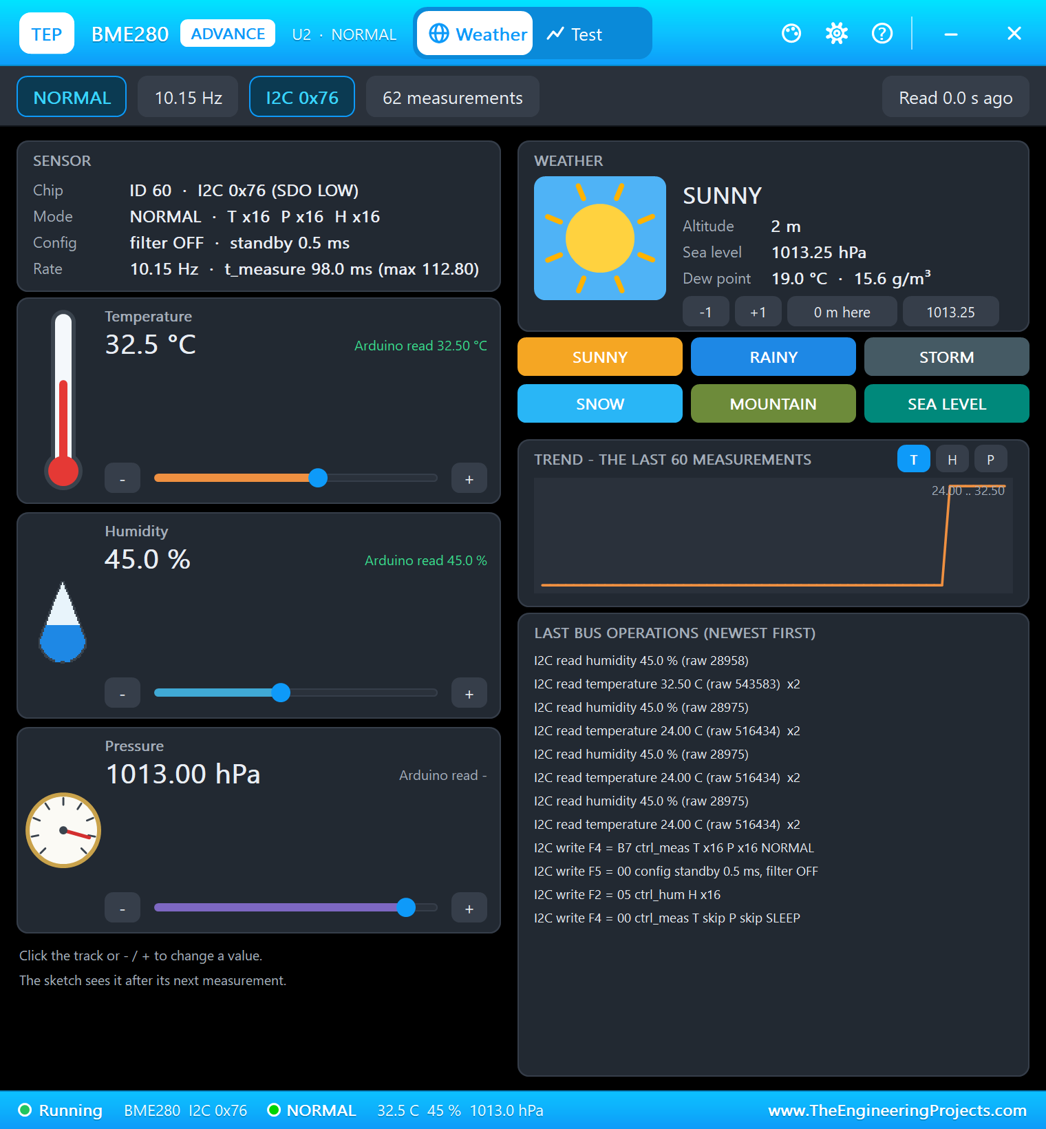
>> The network says: HOT/HUMID (100 %)  32.5 C  45 %
Scores: COLD 0 %  COMFORT 0 %  HOT/HUMID 100 %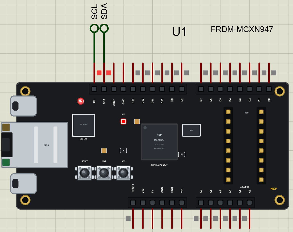
Here is the complete circuit while the simulation runs:
A Cold Room
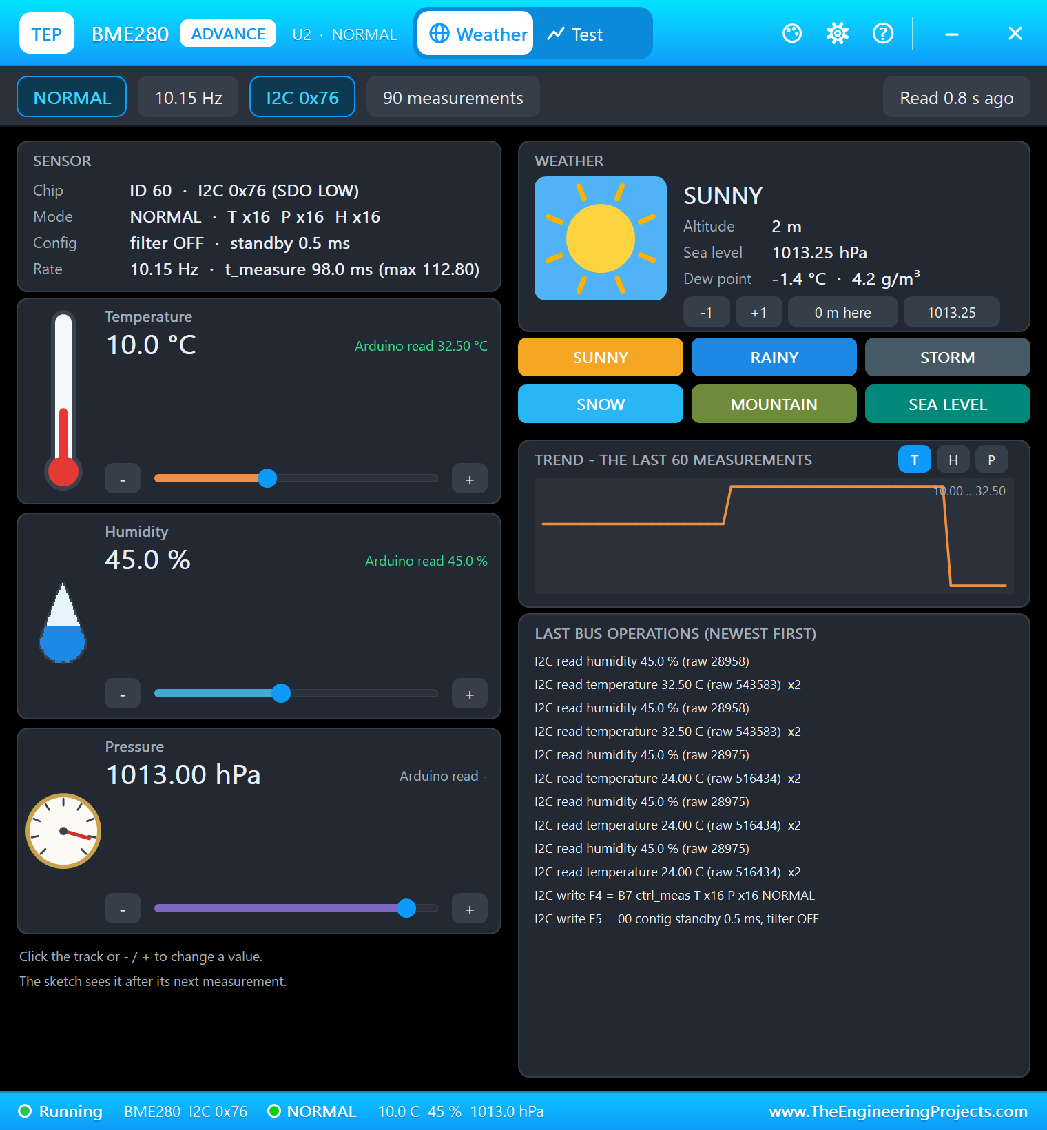
Click the track at about 10 C: COLD, and the LED turns blue:
Warm and Sticky
Now the interesting case: set 25 C, a comfortable temperature, and raise the humidity to about 85 %. The network has learned that humid air is not comfortable either, and says HOT/HUMID. Back to 45 % and it is green again. SW3 runs the self-test:
>> The network says: COLD (100 %)  10.0 C  45 %
>> The network says: COMFORT (100 %)  25.0 C  45 %
>> The network says: HOT/HUMID (100 %)  25.0 C  86 %
>> The network says: COMFORT (100 %)  25.0 C  46 %
Self-test:
  24 C 45 %  ->  COMFORT
  30 C 45 %  ->  HOT/HUMID
  10 C 45 %  ->  COLD
  25 C 85 %  ->  HOT/HUMID
  16 C 60 %  ->  COLD
  21 C 55 %  ->  COMFORT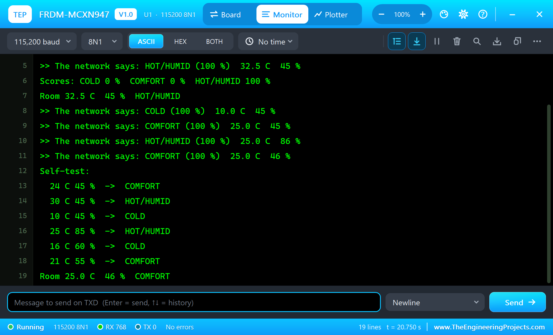
Why So Sure?
The scores show 100 % for the winner most of the time. The network was trained until its outputs are far apart, so softmax turns them into near-certain probabilities. Close to a border - for example at 28 C or at 70 % - the scores come closer, and a larger network trained with more varied examples would give smoother probabilities. That is the kind of model the NPU is made for.
Try It Yourself
- Change the rules in tools\train_comfort_net.py, for example COLD below 20 C, train again and paste the new weights.
- Blink the LED yellow (red and green together) when the top score is below 80 %.
- Add the pressure as a third input and teach the network to warn of a coming storm.
- Use SW2 to switch between the comfort network and a second one for a greenhouse.
Ideas to Extend the Demo
- Log every change of class with the time, so you can see how the room changed over a day.
- Add a relay on D7 that starts a fan when the network says HOT/HUMID.
- Show the three scores as bars on an OLED display on the I2C bus.
- Collect real readings, label them yourself and train the network on your own room.
Your Own Sketches
Write the sketch in the Arduino IDE with the board NXP FRDM-MCXN947 (TEP Proteus), use Sketch > Export Compiled Binary and set the part's PROGRAM property to the .hex. Remember that each colour of the RGB LED is active LOW.
Moving to a Real FRDM-MCXN947
- Install MCUXpresso IDE with the FRDM-MCXN947 SDK, or Zephyr with the board frdm_mcxn947.
- Copy
infer()and the weights into your C project: they are plain C and need no library. - Read the BME280 with the SDK's I2C driver on the Arduino header's SDA and SCL.
- Drive the RGB LED pins LOW to light a colour, as in the sketch.
- For bigger models, train them in TensorFlow or PyTorch and use NXP's eIQ tools to run them on the NPU.
The data flow stays the same: read the sensor, scale the inputs, run the network, act on the class.
Things to Know Before Using a Real FRDM-MCXN947
- 3.3 V logic: the headers are 3.3 V; check a 5 V shield before you plug it in.
- The RGB LED: each colour is active LOW - HIGH switches it off.
- Shared pins: some header pins are shared with the camera, LCD or Ethernet; the board's user manual lists them.
- Scale the inputs: a network expects its inputs in the same range as in training - here (T - 22) / 10 and (H - 50) / 30.
Properties of the FRDM-MCXN947
| Property | What it does |
|---|---|
| PROGRAM | the sketch: a .hex from TEP Boards for Proteus (board "NXP FRDM-MCXN947") |
| MONITOR, BAUD, AUTOOPEN | the built-in serial monitor: on, its baud rate (115200), open at Run |
Troubleshooting
- The LED looks inverted: each colour of the RGB LED lights when its pin is LOW.
- A colour mixes: switch the other two colours off (HIGH) when you light one.
- A button seems dead: use
INPUT_PULLUPand act on the change to LOW. - "BME280 not found": check SDA and SCL, and the address 0x76.
- A number goes wrong above 32767: int is 16 bits in the simulation - use long.
Limitations of the Simulation
- Your sketch is one program: the second core and the NPU are not modelled, and the demo's network runs in the sketch.
- The Ethernet jack, the high-speed USB, the mikroBUS socket and the camera and LCD headers are drawn, not modelled.
- Your sketch gets 8 KB of RAM in the simulation, and int is 16 bits there.
- NXP, FRDM, MCX and eIQ are names of NXP Semiconductors and Arduino of Arduino; this library is not made or endorsed by them or by Labcenter.
- Tested in Proteus 8.5 in November 2026 (the demo as shipped, about 21 s of simulation). Proteus 7 is not supported.
So, that was all about the FRDM-MCXN947 Library for Proteus. I hope it helps you try your edge AI ideas in a simulation before you buy the board - the sensor, the network and the LED, all on one sheet. For a Silicon Labs board with its own AI accelerator, see our xG24 Dev Kit Library for Proteus. If you have any questions, ask in the comments and I will help you out. Till the next tutorial, take care and have fun!

Comments
0