


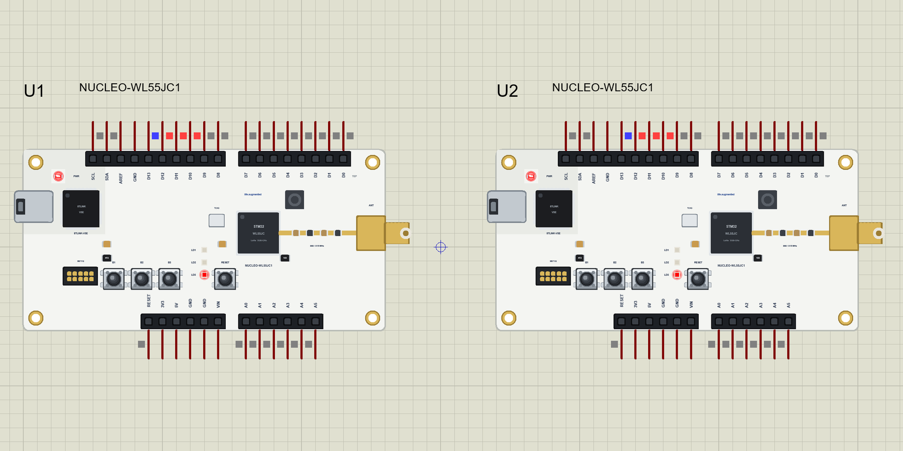
NUCLEO-WL55JC1 Library for Proteus: STM32WL LoRa Pager Simulation


Hello friends, I hope you all are doing great. Today, I am going to share the NUCLEO-WL55JC1 Library for Proteus, so you can run a LoRa simulation of ST's STM32WL Nucleo board. The NUCLEO-WL55JC1 carries the STM32WL55, a dual-core microcontroller with a sub-GHz radio inside, on a Nucleo board with Arduino Uno headers, an SMA socket for the antenna, three coloured LEDs and three user buttons. With this library it runs your Arduino sketch in Proteus 8.5, sends and receives LoRa packets over a distance you choose, and its LEDs and buttons work with a click.
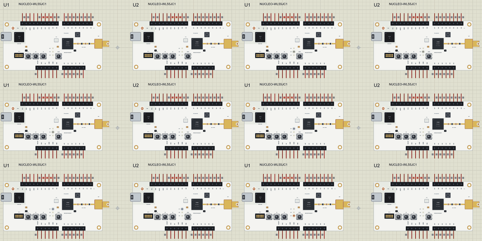
NUCLEO-WL55JC1 Library for Proteus
Latest version: V1.0 (November 2026, this tutorial)
Helping Tools
- Laptop WiFi Monitor: a laptop on the Wi-Fi of your design: a browser, a TCP / UDP terminal and ping
- Mobile WiFi Monitor: a smartphone that opens the pages of your board and sends it commands
- Serial Monitor Advance: a serial terminal window for the UART of your board
For the demo we built a two-way LoRa pager for a farm. One board stays at the farmhouse, the other is the worker's pager 2 km away in the fields. The base sends a message with a button, the pager lights the matching lamp, and the worker answers with a button of their own - with no Wi-Fi and no phone signal at all.
NOTICE: Proteus has no STM32WL55 model, so our team has put a lot of effort into building this board ourselves: the headers, the LEDs, the buttons and the LoRa radio are all our own model, and your sketch compiles with our free TEP Boards for Proteus add-on. Your feedback is the fuel that keeps us going, so please tell us what you think in the comments below. And if our free libraries help you, you can buy us a coffee. So, let's get started with the NUCLEO-WL55JC1 Library for Proteus:
What is the NUCLEO-WL55JC1?
The NUCLEO-WL55JC1 is ST's STM32WL Nucleo-64 board for the high sub-GHz band, 865 to 928 MHz. Its STM32WL55JC puts two Arm cores and a complete radio in one package: a Cortex-M4 and a Cortex-M0+, both at 48 MHz, and a transceiver for 150 to 960 MHz that speaks LoRa, (G)FSK, (G)MSK and BPSK. The chip has 256 KB of flash and 64 KB of RAM. The board adds an STLINK-V3E debugger with its micro-USB, a MIPI debug connector, a 32 MHz TCXO, a switching regulator, the RF matching network and an SMA socket for the antenna that comes in the box, three user LEDs (LD1 blue, LD2 green, LD3 red), three user buttons (B1, B2, B3), RESET and the Arduino Uno V3 and ST morpho headers.
| Part | The real NUCLEO-WL55JC1 | In the library |
|---|---|---|
| MCU | STM32WL55JC: Cortex-M4 + Cortex-M0+ at 48 MHz | your Arduino sketch |
| Radio | sub-GHz, 150 to 960 MHz: LoRa, (G)FSK, (G)MSK, BPSK | LoRa (the LoRa library) |
| LEDs | LD1 blue, LD2 green, LD3 red | LED1, LED2, LED3 (LED_BLUE, LED_GREEN, LED_RED) |
| Buttons | B1, B2, B3, RESET | B1_BTN, B2_BTN, B3_BTN, RESET |
| Headers | Arduino Uno V3, ST morpho | the Arduino Uno pins (the morpho rows are left out) |
| Memory | 256 KB flash, 64 KB RAM | about 256 KB of flash, 8 KB of RAM |
A Radio Inside the Microcontroller
Most LoRa boards pair a microcontroller with a separate radio chip on an SPI bus, like the Heltec WiFi LoRa 32 V3 Library for Proteus with its SX1262. The STM32WL puts the radio on the same die: it is still a Semtech-style sub-GHz transceiver, but it sits on an internal bus, so there are no SPI wires to route, fewer parts and less power. The second core can run a LoRaWAN stack on its own while the first core runs the application, or the whole program can run on one core. ST's STM32CubeWL package has examples for LoRaWAN, Sigfox and plain LoRa links, and the board is certified for LoRaWAN 1.0.4.
What Is LoRa?
LoRa is a radio modulation made for long range at low data rates. Each symbol is a chirp, a tone that sweeps across the channel, and the receiver can pick these chirps out of noise that is stronger than the signal itself. That is why a few milliwatts reach several kilometres in open country, and why one small battery can run a LoRa sensor for years. The price is speed: a LoRa link carries a few hundred bytes per second at best, which is plenty for a temperature, a tank level or a short message.
Spreading Factor, Range and Speed
The spreading factor, SF7 to SF12, sets how long each chirp lasts. A higher factor doubles the time per step and makes the link harder to break: at SF7 a Semtech receiver still decodes a packet at an SNR of about -7.5 dB, at SF12 at about -20 dB. The packet takes much longer in the air, though, and regional rules limit how long a device may transmit, for example 1 % of the time in most of the European 868 MHz band. Most designs start at SF7 with a 125 kHz channel, as our demo does, and raise the factor only when the range is not enough.
JC1 and JC2: Two Bands
ST makes the board in two versions with different RF parts around the same chip. The NUCLEO-WL55JC1 is matched for the high band, 865 to 928 MHz, which covers the 868 MHz band in Europe and the 915 MHz band in the USA. The NUCLEO-WL55JC2 is matched for the low band, around 433 and 470 MHz. Pick the version for your country, and always use an antenna made for that band.
Where Is It Used?
The STM32WL family is at home wherever devices are spread over a large area and run on batteries: water and gas meters, farm sensors for soil, weather and water tanks, asset trackers, street lights, parking sensors and alarms in remote buildings. The Nucleo board is the usual starting point for such products and for university courses on LPWAN networks. For LoRa with a separate radio, see our Arduino MKR WAN 1310 Library for Proteus; for an ST board with Bluetooth LE, see our NUCLEO-WB55RG Library for Proteus.
A simulation lets you build and test the logic of a radio link before two boards and two antennas are on the desk: the packets, the confirmations, the repeats and the timing. When the protocol works in the Proteus simulation, the real boards only have to confirm it.
Features of the NUCLEO-WL55JC1 Library for Proteus
- The board as it looks: the white Nucleo PCB with the STLINK-V3E and its USB, the MIPI connector, the STM32WL55, the TCXO, the coil of the switching regulator, the RF line with its matching network and the SMA socket, LD1 to LD3, B1 to B3, RESET and the Arduino Uno headers, drawn compact, with our small TEP signature.
- Your sketch: a .hex for "ST NUCLEO-WL55JC1 (TEP Proteus)" with the STM32duino board's names: D0 to D15, A0 to A5, LED1 to LED3 (LED_BLUE, LED_GREEN, LED_RED) and B1_BTN to B3_BTN.
- LoRa: the LoRa library with its usual calls; every TEP LoRa board in the same simulation hears it, and the property LORADIST sets the distance, so the RSSI and the SNR follow it.
- Real LEDs and buttons: the LEDs light in their own colours when HIGH; the buttons are clicked on the board.
- A complete package: about 3.3 MB with the part, the add-on and the two-board demo, without the source code of the models.
The NUCLEO-WL55JC1 in Proteus Simulation
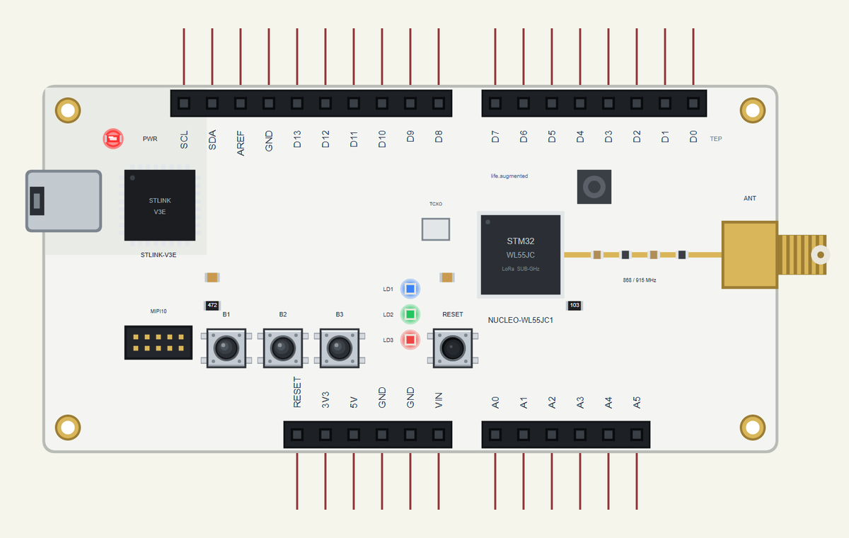
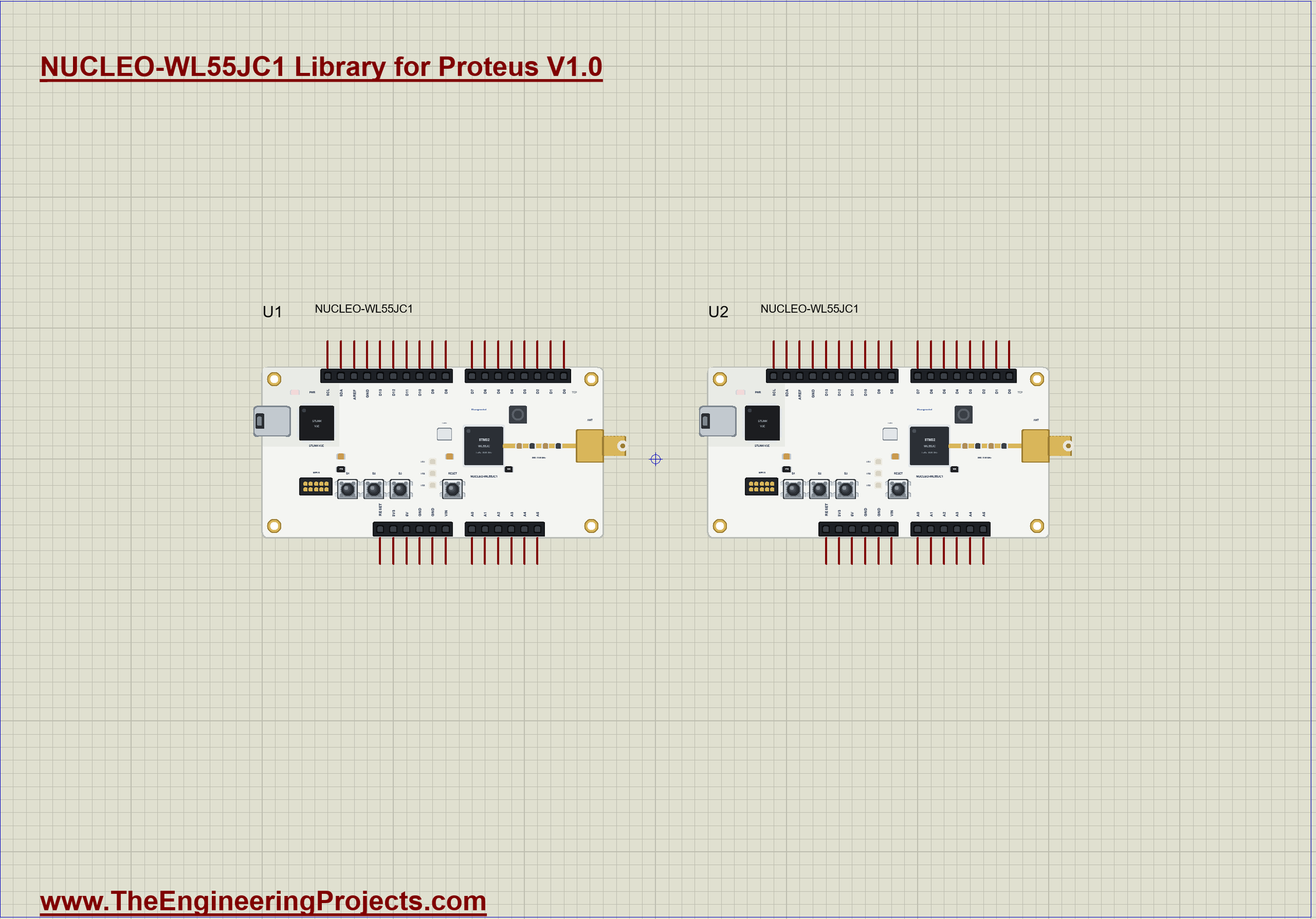
Search NUCLEO-WL55 in Pick Devices; the device is in TEPWL55.LIB (Microprocessor ICs, LoRa Boards), with the prefix U. The STLINK's USB opens the serial monitor.
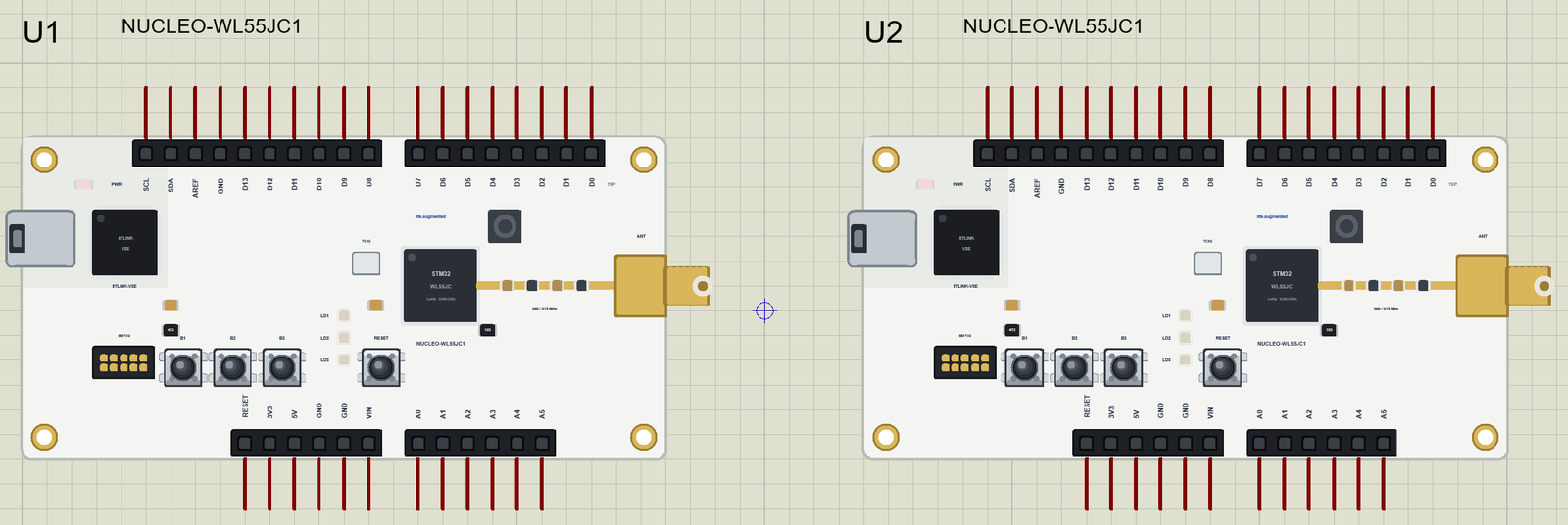
The Pins
| Pins | What the library does with them |
|---|---|
| D0 to D13 | GPIO, PWM with analogWrite, attachInterrupt; D0 / D1 Serial1; D10 to D13 SPI |
| SDA, SCL | D14 and D15: Wire, the I2C bus |
| A0 to A5 | analogRead 0 to 1023 for 0 to 3.3 V, or GPIO |
| LED1, LED2, LED3 | LD1 blue, LD2 green, LD3 red, lit when HIGH |
| B1_BTN, B2_BTN, B3_BTN | B1, B2, B3, LOW when pressed (USER_BTN is B1_BTN) |
| 3V3, 5V, GND, RESET | the supply and the reset |
The radio is inside the board, so it uses none of the header pins: shields on the Arduino headers keep all their pins.
Download NUCLEO-WL55JC1 Library for Proteus
Click the button below to download NUCLEO-WL55JC1-Library-for-Proteus-v1.0.zip (about 3.3 MB, without the source code of the models):
NUCLEO-WL55JC1 Library for Proteus V1.0- README.txt: installation, the demo, the pins, the properties, troubleshooting and the limits.
- Proteus Library Files:
TEPWL55.LIB. - Proteus Model Files:
TEPNET.DLL. - Arduino Code: the two demo sketches and the TEP Boards for Proteus add-on 1.71.0, with LoRa.
- Proteus Simulation: the demo project, its two HEX files and a copy of the DLL.
No Proteus yet? Read How to Download and Install Proteus 7 and 8. New to libraries? Follow How to Install a New Library in Proteus.
How to Install NUCLEO-WL55JC1 Library for Proteus
- Close Proteus and extract the whole zip file, for example to your Desktop.
- Copy the files from Proteus Library Files into the LIBRARY folder of Proteus.
- Copy
TEPNET.DLLfrom Proteus Model Files into the MODELS folder, replacing an older one. - Delete
TEPWL55.IDXfrom the LIBRARY folder if it is there. - For your own sketches, copy Arduino Code\TEP Boards for Proteus\hardware into your Arduino sketchbook (Documents\Arduino) and restart the Arduino IDE; the board is ST NUCLEO-WL55JC1 (TEP Proteus).
- Start Proteus, press P and search for NUCLEO-WL55.
Demo: a Two-Way LoRa Pager in Simulation
On a big farm the worker in the far field is often out of reach: no Wi-Fi, a weak phone signal or none, and a shout does not carry 2 km. A LoRa pager solves it with two small boards and no network at all. The farmhouse can call the worker back, check that all is well or warn of a storm, and the worker answers with one button: on my way, all OK, or need help.
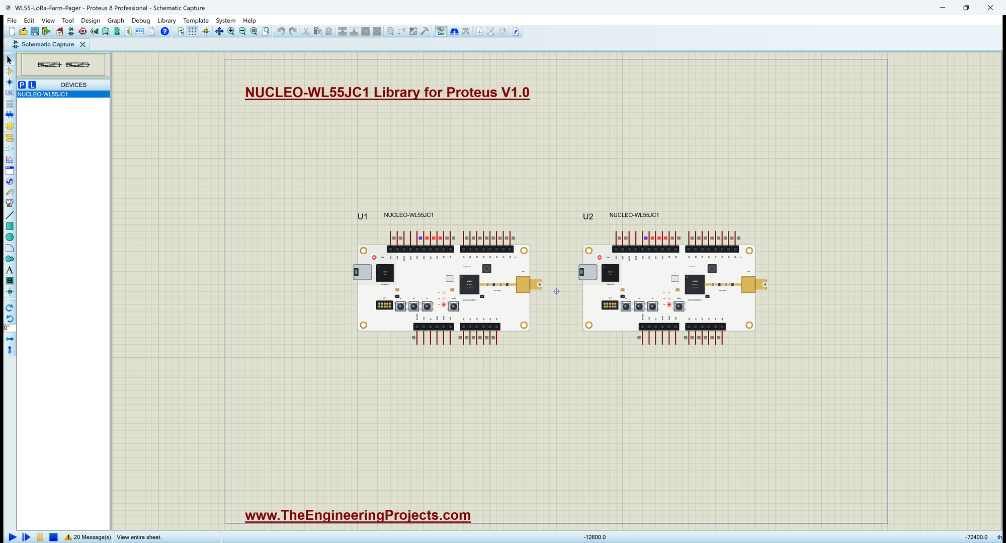
Open WL55-LoRa-Farm-Pager.pdsprj. U1, on the left, runs WL55_Pager_Base.hex: the farmhouse base. U2, on the right, runs WL55_Pager_Field.hex: the worker's pager. Both have LORADIST set to 2 km. There are no wires on this sheet. The serial monitors are the same window as our TEP Serial Monitor Advance for Proteus.
| Button | On the base (U1) | On the pager (U2) |
|---|---|---|
| B1 | Come back to the house (LD1 blue) | On my way (LD1 blue on the base) |
| B2 | Are you OK? (LD2 green) | All OK (LD2 green on the base) |
| B3 | Storm coming - take shelter (LD3 red) | Need help! (LD3 red on the base) |
Sending a Message
A packet is plain text: M for a message, its number and the button. sendCall() sends it and starts the clock for the confirmation:
void sendCall() {
  LoRa.beginPacket();
  LoRa.print(F("M,"));
  LoRa.print(seq);
  LoRa.print(',');
  LoRa.print(call);
  LoRa.endPacket();
  ackDue = millis() + ACK_MS;
}
A press on the base gives the message a new number, lights its lamp and sends it. The lamp stays on until the worker answers:
void newCall(byte k) {
  seq++;
  call = k;
  tries = 1;
  lamps(k);                                                 // the message's lamp: on until the worker answers
  Serial.print(F(">> Message ")); Serial.print(seq); Serial.print(F(": ")); Serial.println(CALLS[k]);
  sendCall();
}
Waiting for the Confirmation
Radio packets can be lost, so the base repeats a message until the pager confirms it, up to three times, and then gives up with a clear warning:
void checkTimeout() {
  if (!tries || millis() < ackDue) return;
  if (tries < TRIES) {
    tries++;
    Serial.print(F("   no answer yet - try ")); Serial.println(tries);
    sendCall();
  } else {
    tries = 0;
    lamps(-1);
    Serial.println(F("!! The pager did not answer - out of range?"));
  }
}
The Pager's Side
The pager confirms every message at once, even a repeated one, because the base may have missed the last confirmation. The number tells it whether the message is new, so a repeat never shows twice:
  if (text.startsWith("M,")) {
    const int k = text.substring(text.lastIndexOf(',') + 1).toInt();
    if (k < 0 || k > 2) return;
    delay(40);                                              // the base needs a moment to go back to receiving
    LoRa.beginPacket();                                     // confirm it, every time (the base may have missed the last one)
    LoRa.print(F("A,"));
    LoRa.print(n);
    LoRa.endPacket();
    if (n == lastCall) return;                              // the same message again
    lastCall = n;
    lamps(k);                                               // the message's lamp: on until the worker answers
    Serial.print(F("<< Message ")); Serial.print(n); Serial.print(F(": ")); Serial.print(CALLS[k]);
    printSignal();
Starting the Radio
Both sketches start the radio the same way, on 868 MHz with 14 dBm of transmit power:
  if (!LoRa.begin(868E6)) {
    Serial.println(F("LoRa failed"));
    while (true) delay(10);
  }
  LoRa.setTxPower(14);
Run the Simulation
Press Run. Both boards start their radios, and each monitor shows its buttons:
NUCLEO-WL55JC1 LoRa Pager - the farmhouse base - The Engineering Projects
LoRa ready on 868 MHz
B1 = come back, B2 = are you OK?, B3 = storm warning

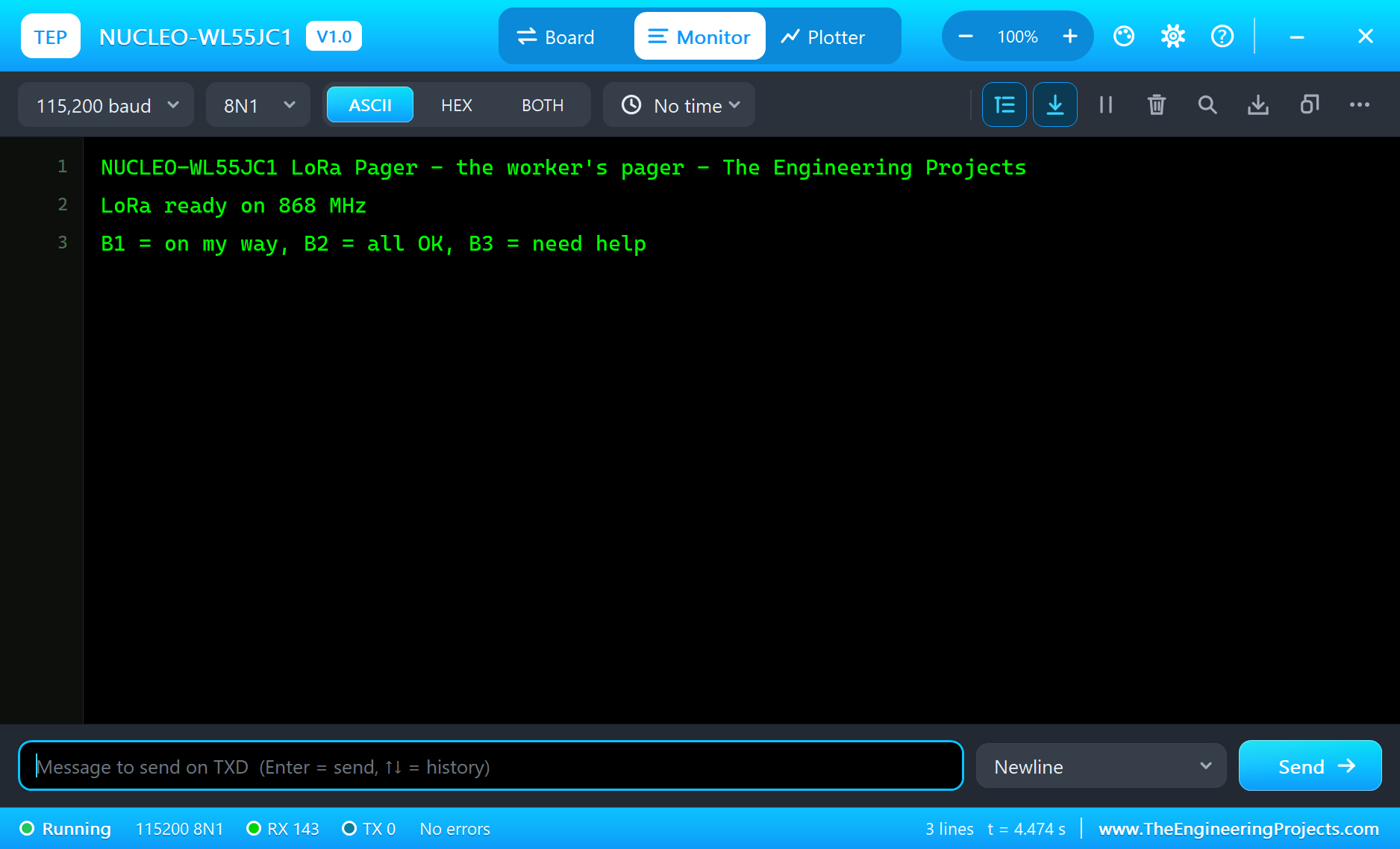
NUCLEO-WL55JC1 LoRa Pager - the worker's pager - The Engineering Projects
LoRa ready on 868 MHz
B1 = on my way, B2 = all OK, B3 = need help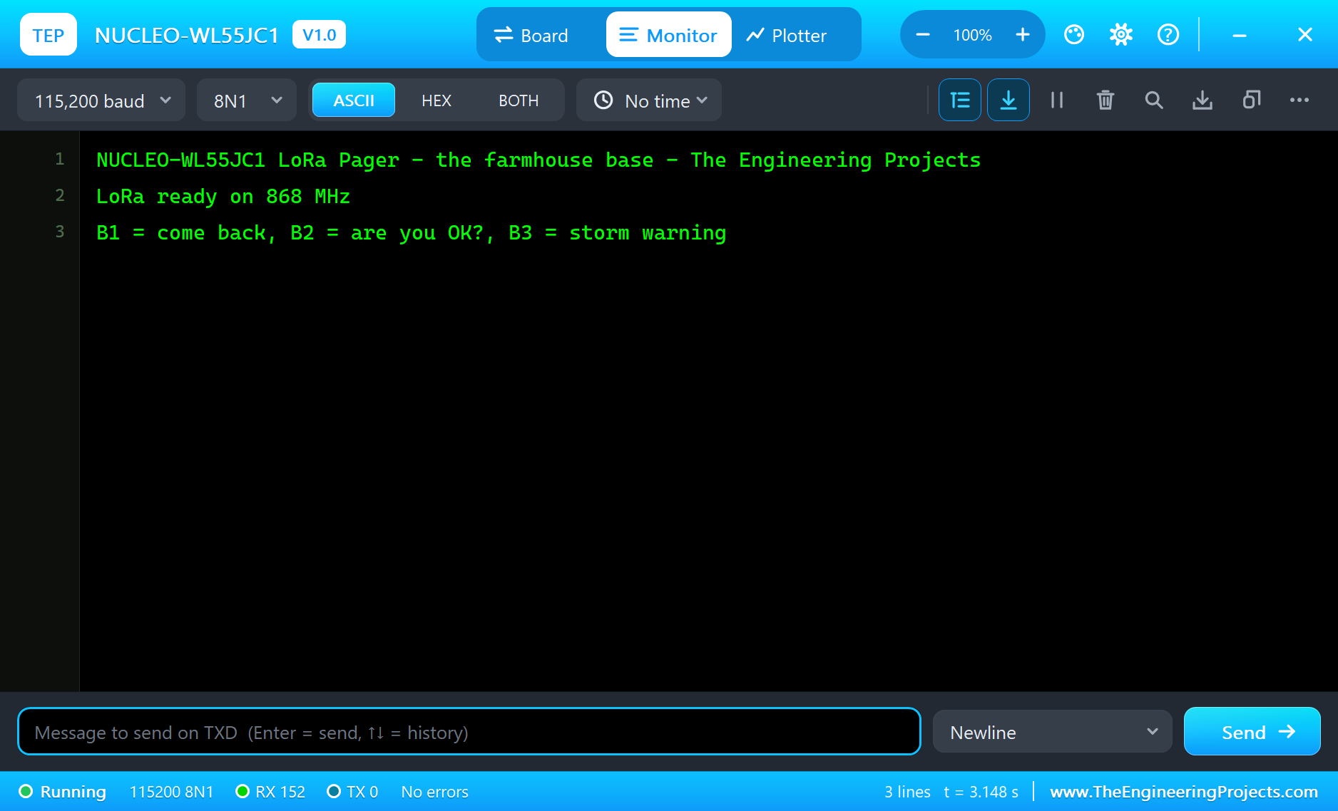
"Are You OK?"
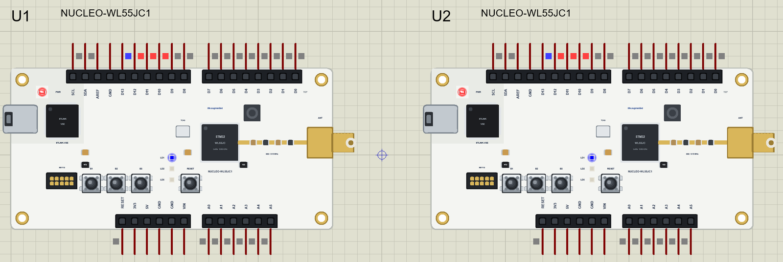
Click B2 on U1. The base sends message 1, LD2 lights on both boards, and the pager confirms it. The base's monitor shows:
>> Message 1: Are you OK?
<< The pager got message 1  (-116 dBm, SNR 0.8 dB)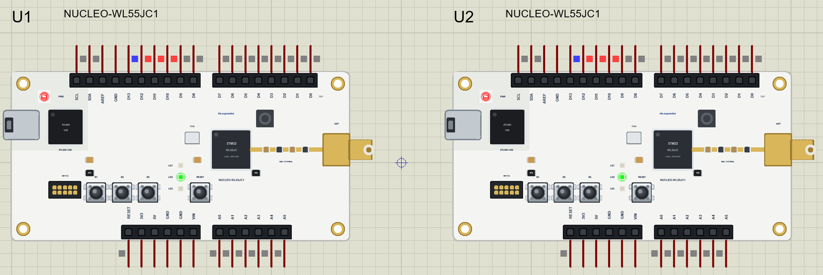
Now click B2 on U2: the worker answers "All OK". The pager's lamp goes off when the base confirms the answer, and the base keeps LD2 on to show the last answer. The pager's monitor shows:
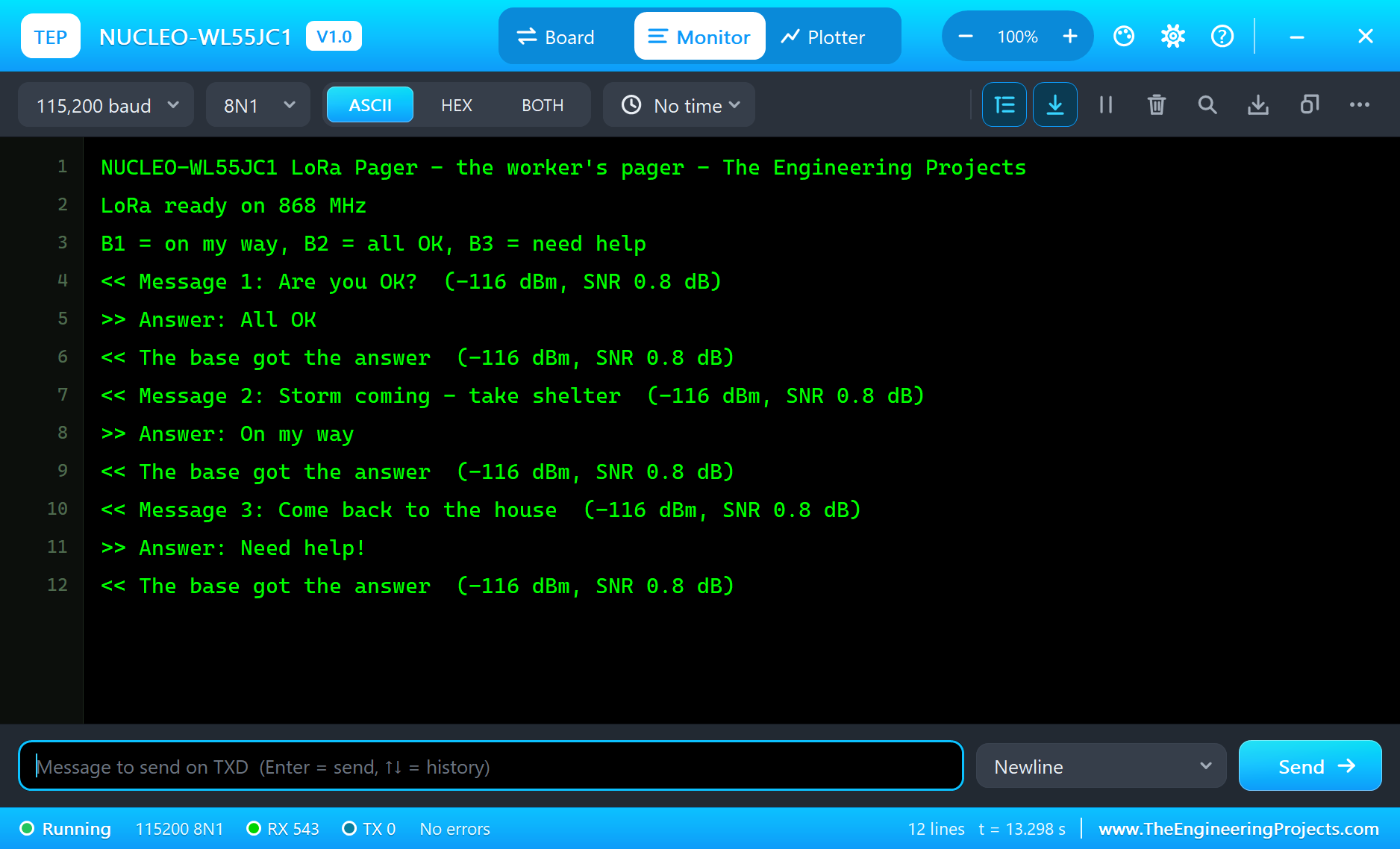
<< Message 1: Are you OK?  (-116 dBm, SNR 0.8 dB)
>> Answer: All OK
<< The base got the answer  (-116 dBm, SNR 0.8 dB)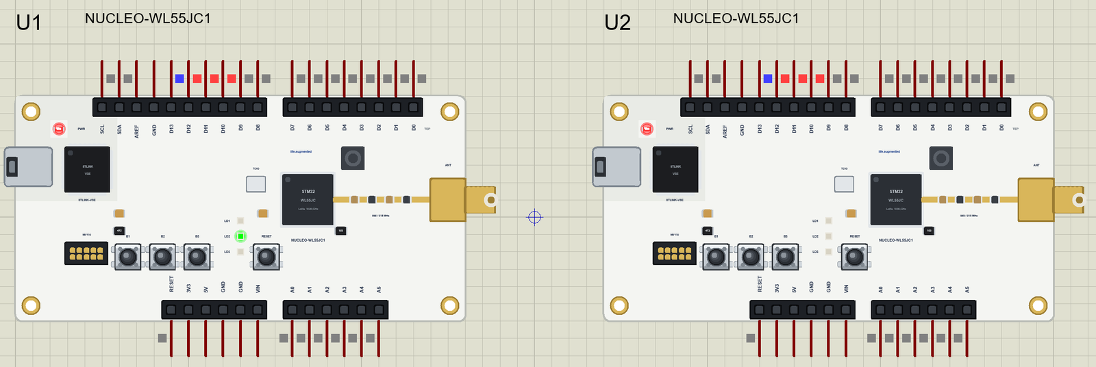
The Storm Warning
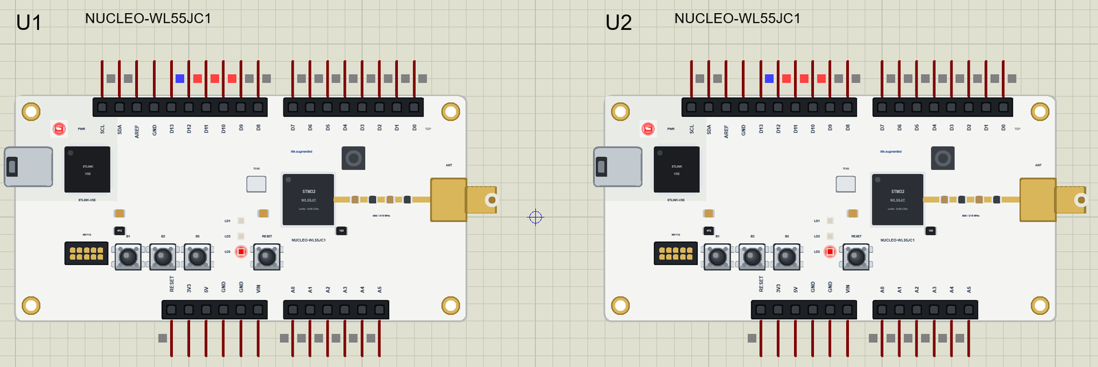
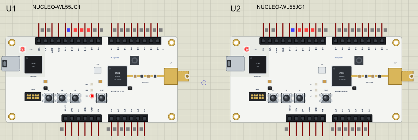
Click B3 on U1: "Storm coming - take shelter". LD3 lights on both boards:
Here is the complete circuit while the simulation runs:
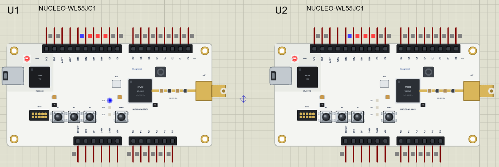
The worker clicks B1 on U2, "On my way", and the base lights LD1:
Come Back - and a Call for Help
Click B1 on U1, "Come back to the house", and LD1 lights on the pager. Then the worker clicks B3: "Need help!", and the base lights LD3:
<< Worker: All OK  (-116 dBm, SNR 0.8 dB)
>> Message 2: Storm coming - take shelter
<< The pager got message 2  (-116 dBm, SNR 0.8 dB)
<< Worker: On my way  (-116 dBm, SNR 0.8 dB)
>> Message 3: Come back to the house
<< The pager got message 3  (-116 dBm, SNR 0.8 dB)
<< Worker: Need help!  (-116 dBm, SNR 0.8 dB)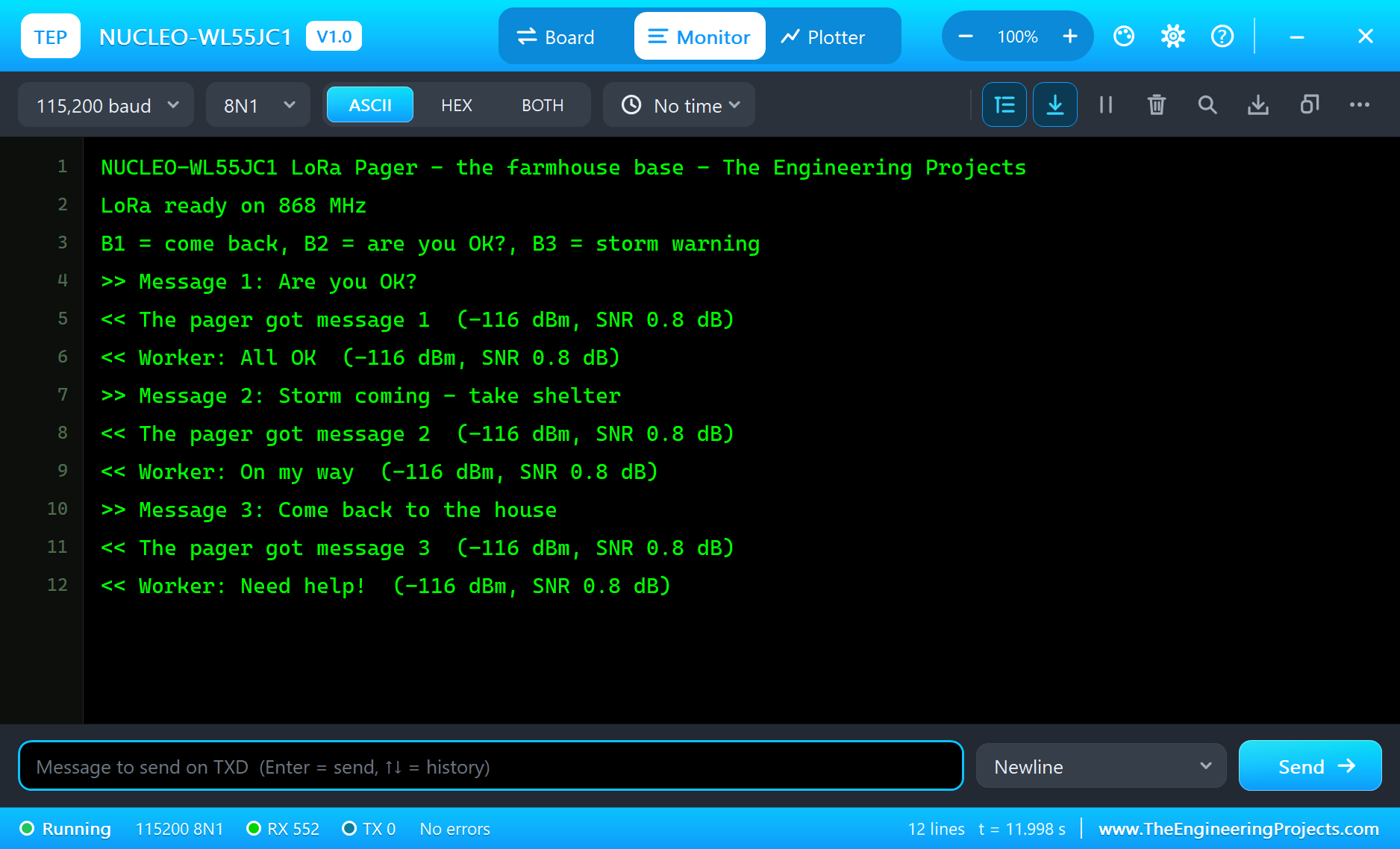
Reading the Signal
Every received packet prints its RSSI, the strength of the signal in dBm, and its SNR, how far the signal stands above the noise. At 2 km both boards hear each other at about -116 dBm with an SNR just above 0 dB: weak for most radios, but comfortable for LoRa at SF7, which still decodes down to about -7.5 dB. Set LORADIST to 10 km or 20 km on both boards and watch the numbers fall; at the far end packets start to go missing, and the repeats in the sketches begin to matter.
Try It Yourself
- Set LORADIST to 15 km on both boards and watch the "try 2" and "try 3" lines appear.
- Call
LoRa.setSpreadingFactor(10)on both boards afterLoRa.begin()and compare the range. - Blink the pager's lamp for the storm warning instead of keeping it on.
- Add a buzzer on D9 with
tone(), so the worker hears a message even with the pager in a pocket.
Ideas to Extend the Pager
- Give every worker their own pager number and let the base call one or all of them.
- Add a GPS module on Serial1 and send the worker's position with every answer.
- Put the pager to sleep between packets to make the battery last for weeks.
- Add a moisture or temperature sensor and send its reading with the "All OK" answer.
Your Own Sketches
Write the sketch in the Arduino IDE with the board ST NUCLEO-WL55JC1 (TEP Proteus), use Sketch > Export Compiled Binary and set the part's PROGRAM property to the .hex. Give every board that should talk to another the same frequency, spreading factor and bandwidth, and set LORADIST on each.
Moving the Pager to Real NUCLEO-WL55JC1 Boards
- Screw the antenna onto the SMA socket of each board before you power it.
- Install the STM32duino core in the Arduino IDE and select the board Nucleo-64, NUCLEO-WL55JC1.
- Install RadioLib and use its STM32WLx class in place of the LoRa library: begin with the frequency, then transmit, receive, getRSSI and getSNR do the same work.
- Set the frequency for your country: 868 MHz in Europe, 915 MHz in the USA.
- Keep the names LED_BLUE, LED_GREEN, LED_RED and B1_BTN to B3_BTN: the board package maps them to the right pins.
The message format, the confirmations and the repeats move across without changes, which is the point of trying the protocol in the simulation first.
Things to Know Before Using a Real NUCLEO-WL55JC1
- Never transmit without an antenna: the power has nowhere to go and can damage the radio.
- Use the right band: the JC1 is for 865 to 928 MHz; keep to the frequencies and the duty cycle allowed where you live.
- 3.3 V logic: the Arduino headers are 3.3 V; check a 5 V shield before you plug it in.
- LoRaWAN needs a network: for LoRaWAN you need a gateway and a network server; a point-to-point link like our pager needs neither.
Properties of the NUCLEO-WL55JC1
| Property | What it does |
|---|---|
| PROGRAM | the sketch: a .hex from TEP Boards for Proteus (board "ST NUCLEO-WL55JC1") |
| MONITOR, BAUD, AUTOOPEN | the built-in serial monitor: on, its baud rate (115200), open at Run |
| LORADIST | the LoRa distance to the other boards: 10 m to 20 km (the demo: 2 km) |
Troubleshooting
- "LoRa failed": include
LoRa.hand callLoRa.begin(868E6)once in setup(). - The other board hears nothing: both need the same frequency, spreading factor and bandwidth; try a smaller LORADIST.
- A reply gets lost: wait about 40 ms after a packet before you answer, and repeat a packet until it is confirmed.
- A button seems dead: use
INPUT_PULLUPand act on the change to LOW. - A number goes wrong above 32767: int is 16 bits in the simulation - use long.
Limitations of the Simulation
- LoRa works between the TEP LoRa boards of one simulation. LoRaWAN, (G)FSK, (G)MSK and BPSK are not modelled, and your sketch is one program: the two cores are not split.
- The MIPI connector and the morpho headers are left out or drawn, not modelled.
- Your sketch gets 8 KB of RAM in the simulation, and int is 16 bits there.
- STM32, Nucleo and ST are names of STMicroelectronics, Arduino of Arduino and LoRa of Semtech; this library is not made or endorsed by them or by Labcenter.
- Tested in Proteus 8.5 in November 2026 (the demo as shipped, about 13 s of simulation). Proteus 7 is not supported.
So, that was all about the NUCLEO-WL55JC1 Library for Proteus. I hope it helps you try your long-range ideas on an STM32WL in a simulation before you buy two boards and two antennas - the messages, the confirmations and the repeats, all on one sheet. If you have any questions, ask in the comments and I will help you out. Till the next tutorial, take care and have fun!

Comments
0