


NUCLEO-H743ZI2 Library for Proteus: STM32H7 Ethernet Simulation


Hello friends, I hope you all are doing great. Today, I am going to share the NUCLEO-H743ZI2 Library for Proteus, so you can run an Ethernet simulation of ST's most powerful Nucleo board. The NUCLEO-H743ZI2 carries the STM32H743, a Cortex-M7 running at 480 MHz, on a Nucleo-144 board with an RJ45 Ethernet jack, three coloured LEDs, a USER button and Arduino Uno headers. With this library it runs your Arduino sketch in Proteus 8.5, serves web pages over its Ethernet cable, and its LEDs and button work with a click.
NUCLEO-H743ZI2 Library for Proteus
Latest version: V1.0 (November 2026, this tutorial)
Helping Tools
- Laptop WiFi Monitor: a laptop on the Wi-Fi of your design: a browser, a TCP / UDP terminal and ping
- Mobile WiFi Monitor: a smartphone that opens the pages of your board and sends it commands
- Serial Monitor Advance: a serial terminal window for the UART of your board
For the demo we built a server room monitor. A BME280 measures the air inside a rack, the LEDs show green, yellow or red, a hot rack raises an alarm, and a dashboard on the board's own web server shows it all on a phone - with an ACK link to acknowledge the alarm.
NOTICE: Proteus has no STM32H743 model, so our team has put a lot of effort into building this board ourselves: the headers, the LEDs, the button and the Ethernet port are all our own model, and your sketch compiles with our free TEP Boards for Proteus add-on. Your feedback is the fuel that keeps us going, so please tell us what you think in the comments below. And if our free libraries help you, you can buy us a coffee. So, let's get started with the NUCLEO-H743ZI2 Library for Proteus:
What is the NUCLEO-H743ZI2?
The NUCLEO-H743ZI2 is ST's Nucleo-144 board for the STM32H7 family. Its STM32H743ZI is an Arm Cortex-M7 at up to 480 MHz with a double-precision floating-point unit and caches, 2 MB of flash and 1 MB of RAM - fast enough for audio, motor control, graphics and networking at the same time. The board adds an STLINK-V3E debugger with its micro-USB, a 10/100 Ethernet port with the LAN8742A PHY and an RJ45 jack, a USB OTG port, three user LEDs (LD1 green, LD2 yellow, LD3 red), the USER button B1 and RESET, and ST's Zio and morpho headers, which include the Arduino Uno V3 pins.
| Part | The real NUCLEO-H743ZI2 | In the library |
|---|---|---|
| MCU | STM32H743ZI: Cortex-M7 at 480 MHz | your Arduino sketch |
| Ethernet | 10/100 RJ45 with the LAN8742A PHY | STM32Ethernet, the cable a click away |
| LEDs | LD1 green, LD2 yellow, LD3 red | LED_GREEN, LED_YELLOW, LED_RED |
| Buttons | B1 USER, B2 RESET | USER_BTN (HIGH when pressed), RESET |
| Headers | ST Zio (Arduino Uno V3) and morpho | the Arduino Uno pins |
| Memory | 2 MB flash, 1 MB RAM | about 256 KB of flash, 8 KB of RAM |
The Most Powerful Nucleo
The STM32H7 family sits at the top of ST's microcontrollers. At 480 MHz with a cache and a double-precision FPU, the H743 does work that used to need a small Linux processor: decoding audio, running a TCP/IP stack and a web server, filtering sensor data and driving a display, all with the hard real-time response of a microcontroller. The Nucleo-144 board makes all of it available for the price of a lunch, with the debugger on the same board.
Why Ethernet on a Microcontroller?
Wi-Fi is easy, but a cable is better wherever the network must not drop: in factories, server rooms, building automation, test benches and laboratories. Ethernet needs no password, has no interference from other radios and gives a fixed, predictable delay. The STM32H743 has a full Ethernet MAC inside; the board adds the PHY chip, which turns the MAC's signals into the voltages on the cable, and the RJ45 jack with its magnetics and its two LEDs for the link and the activity. For an Ethernet board with an ESP32, see our WT32-ETH01 Library for Proteus.
STM32Ethernet and LwIP
On a real NUCLEO-H743ZI2 the Arduino world talks Ethernet through two STM32duino libraries: LwIP, a small TCP/IP stack, and STM32Ethernet, which gives it the familiar Arduino Ethernet API: Ethernet.begin(), EthernetServer, EthernetClient and EthernetUDP. Our board package has STM32Ethernet with the same names, so the same sketch compiles for the simulation and for the real board.
Where Is It Used?
The STM32H7 Nucleo boards are a favourite for industrial and research prototypes: network-connected controllers, data loggers, Modbus TCP and MQTT gateways, motor drives, audio and vision projects and university courses on embedded networking. For ST boards with radios, see our NUCLEO-WL55JC1 Library for Proteus with LoRa.
A simulation lets you build the web pages, the alarms and the network logic before the board and a switch are on the desk. When the dashboard works in the Proteus simulation, the real board only has to confirm it.
Features of the NUCLEO-H743ZI2 Library for Proteus
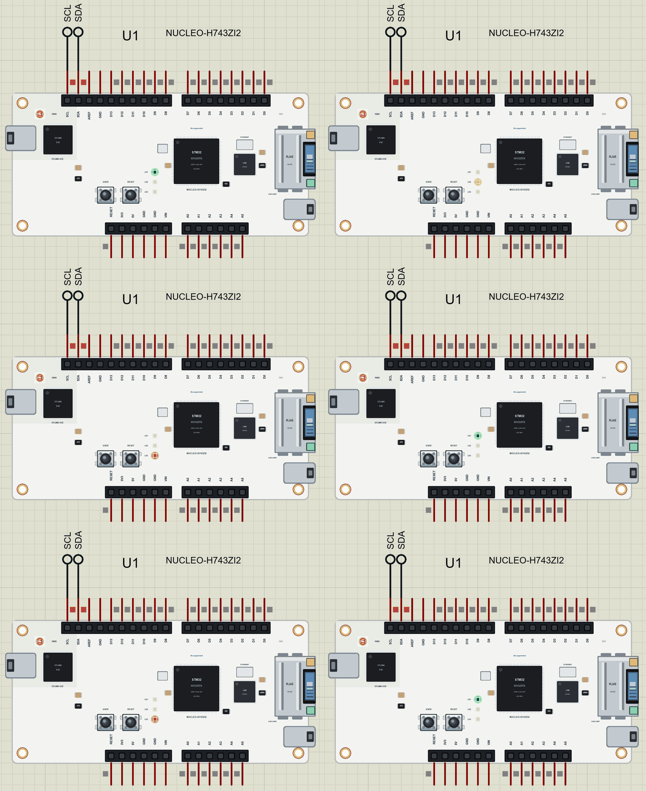
- The board as it looks: the white Nucleo-144 PCB with the STLINK-V3E and its USB, the STM32H743 in its LQFP144, the LAN8742A with its crystal, the RJ45 jack with its LINK and ACT LEDs, the user USB, LD1 to LD3, USER, RESET and the Arduino Uno headers, drawn compact, with our small TEP signature.
- Your sketch: a .hex for "ST NUCLEO-H743ZI2 (TEP Proteus)" with the STM32duino board's names: D0 to D15, A0 to A5, LED_GREEN, LED_YELLOW, LED_RED and USER_BTN.
- Ethernet: STM32Ethernet with a fixed address or DHCP, TCP servers and clients and UDP, to the router, the phone and the other boards of the simulation.
- A real cable: a click on the RJ45 jack pulls the cable out or plugs it in, and the LINK and ACT LEDs follow it.
- Real LEDs and button: the LEDs light in their own colours when HIGH; USER reads HIGH while you hold it, as on the real board.
- A complete package: about 3.8 MB with the part, the add-on, the BME280, the phone and the demo, without the source code of the models.
The NUCLEO-H743ZI2 in Proteus Simulation
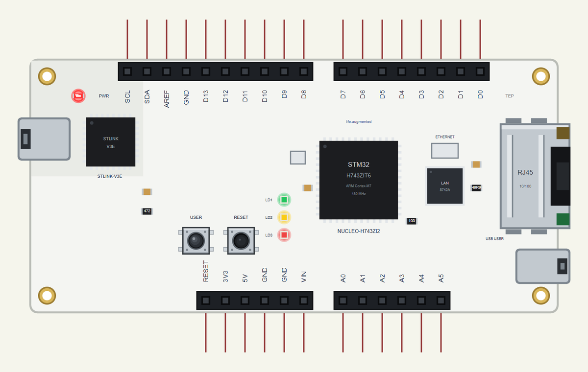
Search NUCLEO-H743 in Pick Devices; the device is in TEPH743.LIB (Microprocessor ICs, Ethernet Boards), with the prefix U. The STLINK's USB opens the serial monitor; a click on the RJ45 jack pulls or plugs the cable.
The Pins
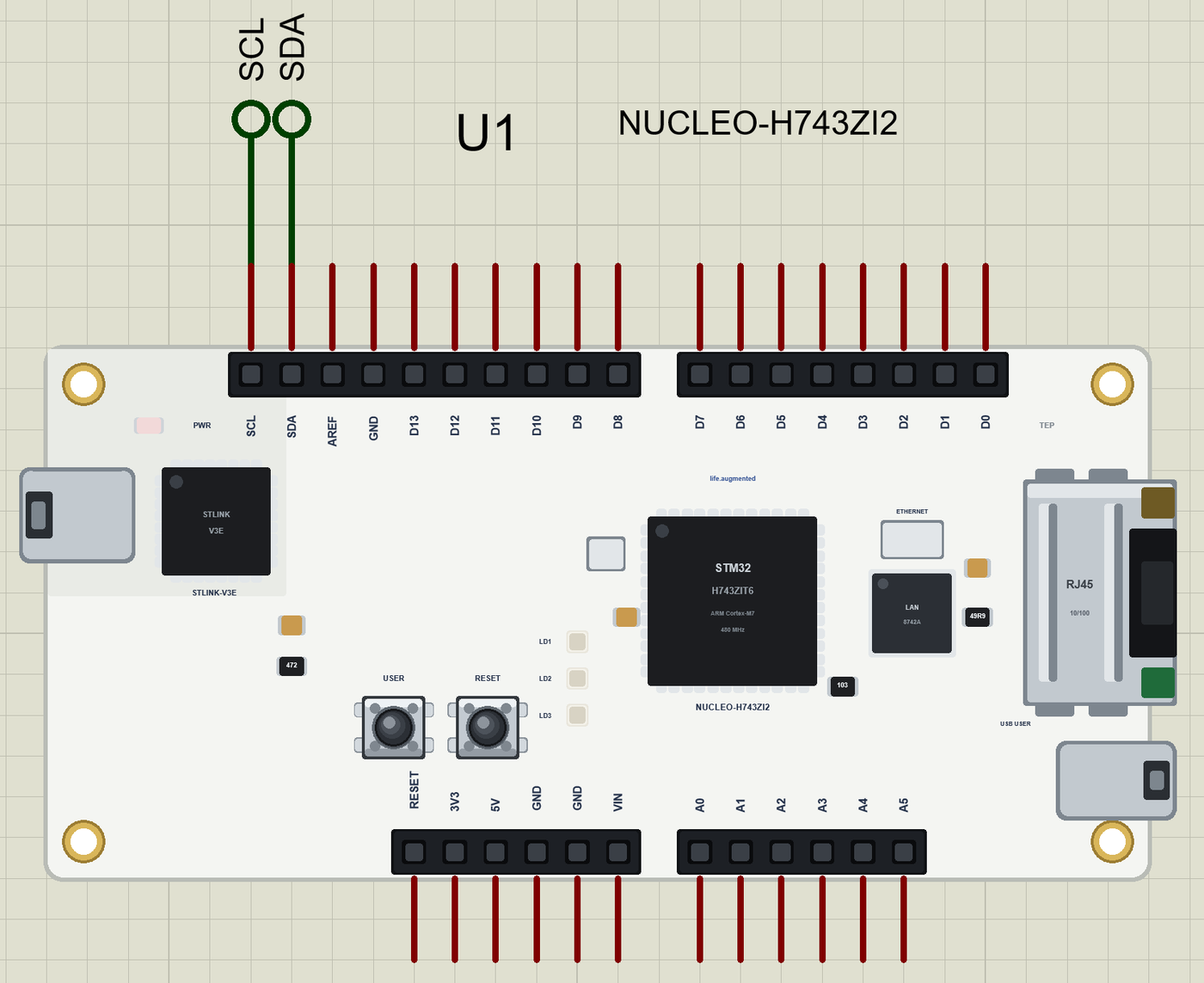
| Pins | What the library does with them |
|---|---|
| D0 to D13 | GPIO, PWM with analogWrite, attachInterrupt; D0 / D1 Serial1; D10 to D13 SPI |
| SDA, SCL | D14 and D15: Wire, the I2C bus |
| A0 to A5 | analogRead 0 to 1023 for 0 to 3.3 V, or GPIO |
| LED_GREEN, LED_YELLOW, LED_RED | LD1, LD2, LD3, lit when HIGH |
| USER_BTN | B1, HIGH while pressed (the board pulls it down) |
| 3V3, 5V, GND, RESET | the supply and the reset |
The Ethernet PHY is inside the board, so it uses none of the header pins: shields on the Arduino headers keep all their pins.
Download NUCLEO-H743ZI2 Library for Proteus
Click the button below to download NUCLEO-H743ZI2-Library-for-Proteus-v1.0.zip (about 3.8 MB, without the source code of the models):
NUCLEO-H743ZI2 Library for Proteus V1.0- README.txt: installation, the demo, the pins, the properties, troubleshooting and the limits.
- Proteus Library Files:
TEPH743.LIB, the BME280 and the phone and laptop:TEPBME280.LIB,TEPMOBILE.LIBandTEPLAPTOP.LIB. - Proteus Model Files:
TEPNET.DLLandTEPBME280.DLL. - Arduino Code: the demo sketch and the TEP Boards for Proteus add-on 1.72.0, with STM32Ethernet.
- Proteus Simulation: the demo project, its HEX file and copies of the DLLs.
No Proteus yet? Read How to Download and Install Proteus 7 and 8. New to libraries? Follow How to Install a New Library in Proteus.
How to Install NUCLEO-H743ZI2 Library for Proteus
- Close Proteus and extract the whole zip file, for example to your Desktop.
- Copy the files from Proteus Library Files into the LIBRARY folder of Proteus.
- Copy the DLLs from Proteus Model Files into the MODELS folder, replacing an older
TEPNET.DLL. - Delete
TEPH743.IDXfrom the LIBRARY folder if it is there. - For your own sketches, copy Arduino Code\TEP Boards for Proteus\hardware into your Arduino sketchbook (Documents\Arduino) and restart the Arduino IDE; the board is ST NUCLEO-H743ZI2 (TEP Proteus). The demo also needs Adafruit BME280 and Adafruit Unified Sensor from the Library Manager.
- Start Proteus, press P and search for NUCLEO-H743.
Demo: an Ethernet Server Room Monitor in Simulation
Servers heat up fast when a fan fails or the air conditioning stops, and a hot rack can shut down a whole office. A small monitor with a temperature sensor, a few lamps and a web page catches the problem early. It sits in the rack, wired to the same network as the servers, so the dashboard is always reachable from any phone or PC on the LAN.
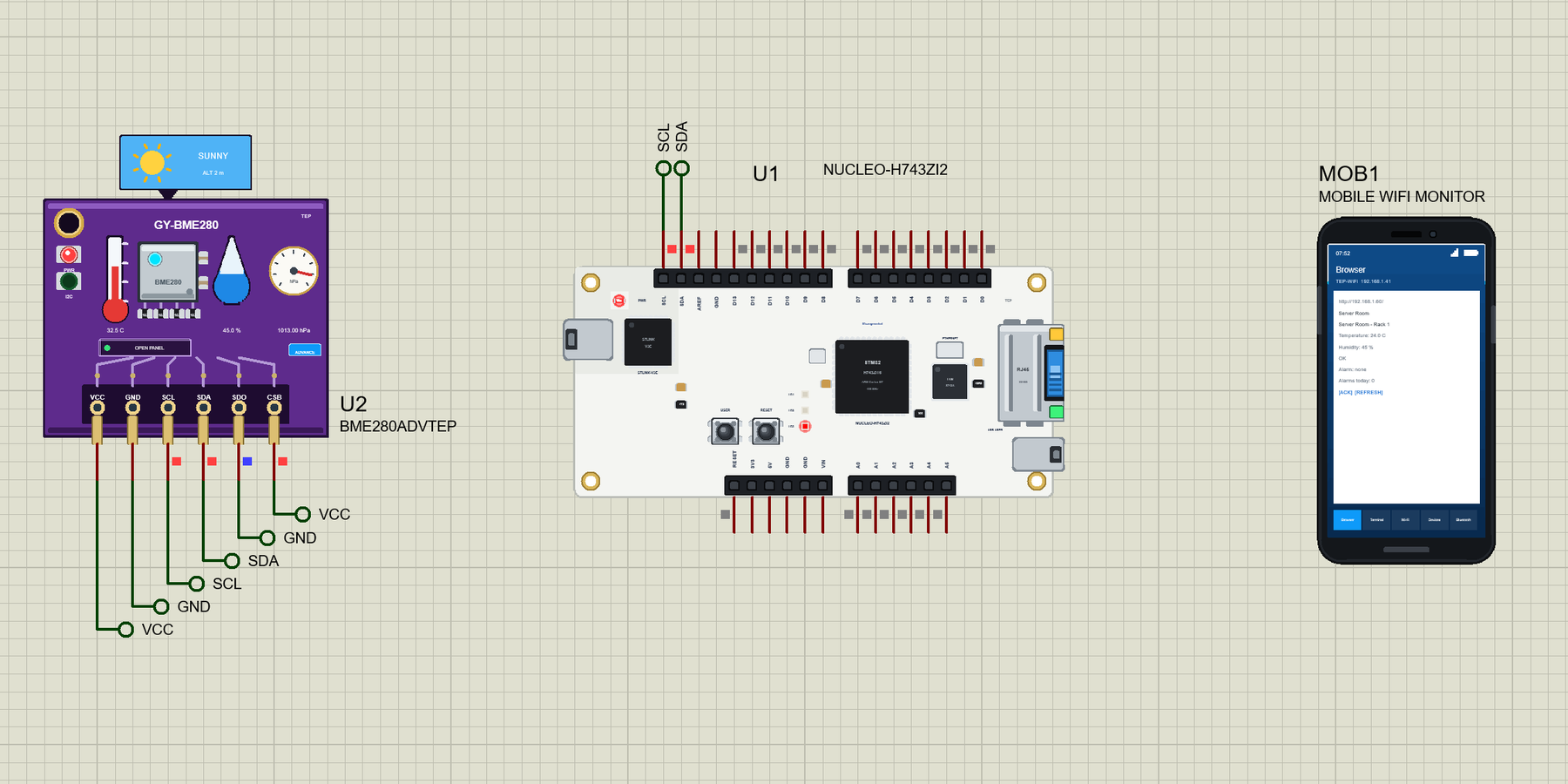
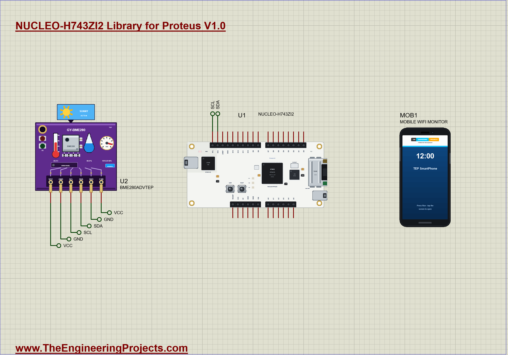
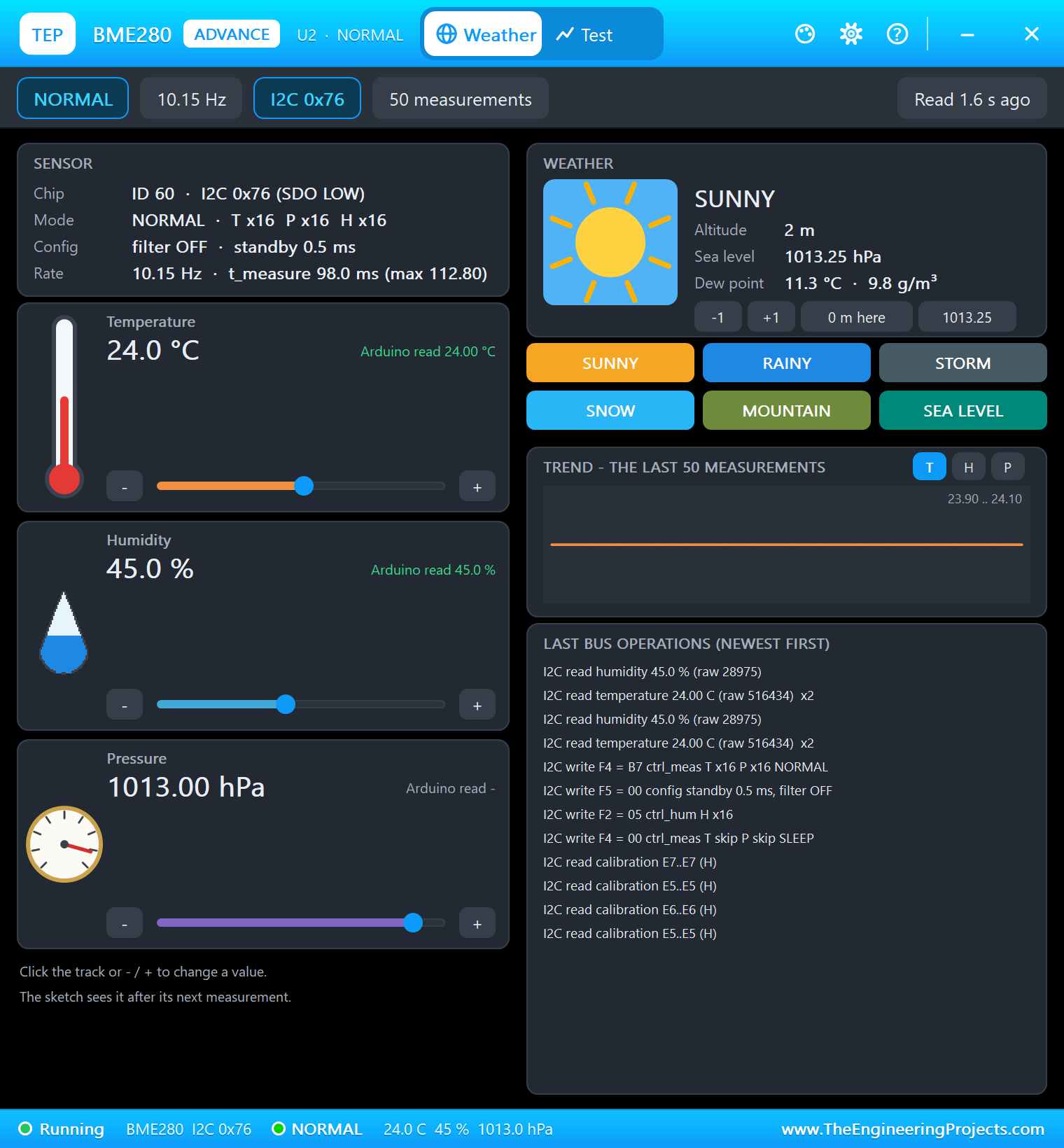
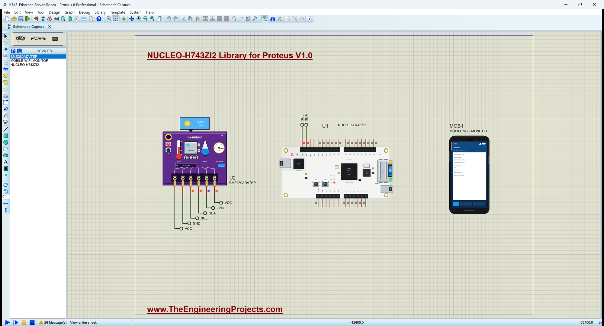
Open H743-Ethernet-Server-Room.pdsprj. U1 runs H743_Server_Room.hex. U2 is our BME280 (Advance) on SDA and SCL. MOB1 is our Mobile WiFi Monitor, a phone on the router's Wi-Fi; its browser's home page is the board's dashboard. The serial monitor is the same window as our TEP Serial Monitor Advance for Proteus.
| Rack temperature | Level | LED |
|---|---|---|
| below 28 C | OK | LD1 green |
| 28 C to 32 C | WARM | LD2 yellow |
| 32 C or more | HOT - an alarm | LD3 red |
Reading the Rack
Every 2 seconds readRack() reads the BME280 and works out the level. Only a change of level does anything, so the LEDs and the alarm never flicker:
void readRack() {
  tempC = bme.readTemperature();
  humidity = bme.readHumidity();
  nextRead = millis() + READ_MS;
  const byte now = tempC >= HOT_C ? LEVEL_HOT : tempC >= WARM_C ? LEVEL_WARM : LEVEL_OK;
  if (now == level) return;
  level = now;
  showLevel();
The USER Button
On the Nucleo-144 boards the USER button is pulled down, so it reads HIGH while pressed. The sketch acts on the change to HIGH:
void readButton() {
  const bool now = digitalRead(USER_BTN);
  if (now == lastButton) return;
  lastButton = now;
  if (now == HIGH) acknowledge(F("the USER button"));
}
A Small Web Server
handleWeb() takes the next connection, reads the first line of the request and skips the rest of the header. /ack acknowledges the alarm, /json sends the numbers, and everything else gets the dashboard:
void handleWeb() {
  EthernetClient client = server.available();
  if (!client) return;
  String request;                                           // the first line: "GET /ack HTTP/1.1"
  const unsigned long t0 = millis();
  while (client.connected() && millis() - t0 < 1000) {
    if (!client.available()) continue;
    const String line = client.readStringUntil('\n');
    if (!request.length()) request = line;
    if (line.length() <= 1) break;                          // the empty line after the header
  }
  if (request.startsWith("GET /ack")) acknowledge(F("the web page"));
  if (request.startsWith("GET /json")) sendJson(client);
  else sendPage(client);
  delay(1);
  client.stop();
}
Inside the Dashboard Page
sendPage() writes a complete HTTP answer: a status line, the content type, an empty line and then the HTML. Every fixed piece of text sits in flash with F(), so the page costs almost no RAM, and only the numbers are printed in between. The level gets its own colour, and the two links at the bottom are plain addresses: /ack and /. Any other program on the network can read /json instead, for example a script on a PC that collects the readings of every rack.
Why a Fixed Address?
A monitor that people open from a bookmark should always be at the same address. DHCP may give the board a different one after a power cut, so server rooms usually give such devices a fixed address, or reserve one for them in the router. The sketch uses 192.168.1.60, which is free on the TEP network of the simulation; on your own network pick one outside the router's DHCP range.
Watching the Cable
Ethernet.linkStatus() tells whether the cable is in. The sketch prints a warning the moment it is pulled out:
void watchLink() {
  const bool up = Ethernet.linkStatus() == LinkON;
  if (up == linkWas) return;
  linkWas = up;
  Serial.println(up ? F(">> Ethernet cable in - the dashboard is back") : F(">> Ethernet cable out!"));
}
In setup(), one line gives the board its fixed address and starts the PHY, and the server starts listening:
  Ethernet.begin(ip);
  if (Ethernet.linkStatus() != LinkON) Serial.println(F("No Ethernet link - plug the cable in"));
  server.begin();
Run the Simulation
Press Run. The board starts its Ethernet, prints its address and the dashboard's link, and the rack is OK, so LD1 lights green:
NUCLEO-H743ZI2 Server Room Monitor - The Engineering Projects
Ethernet up, IP 192.168.1.60
Dashboard: http://192.168.1.60/
Rack 24.0 C  45 %  OK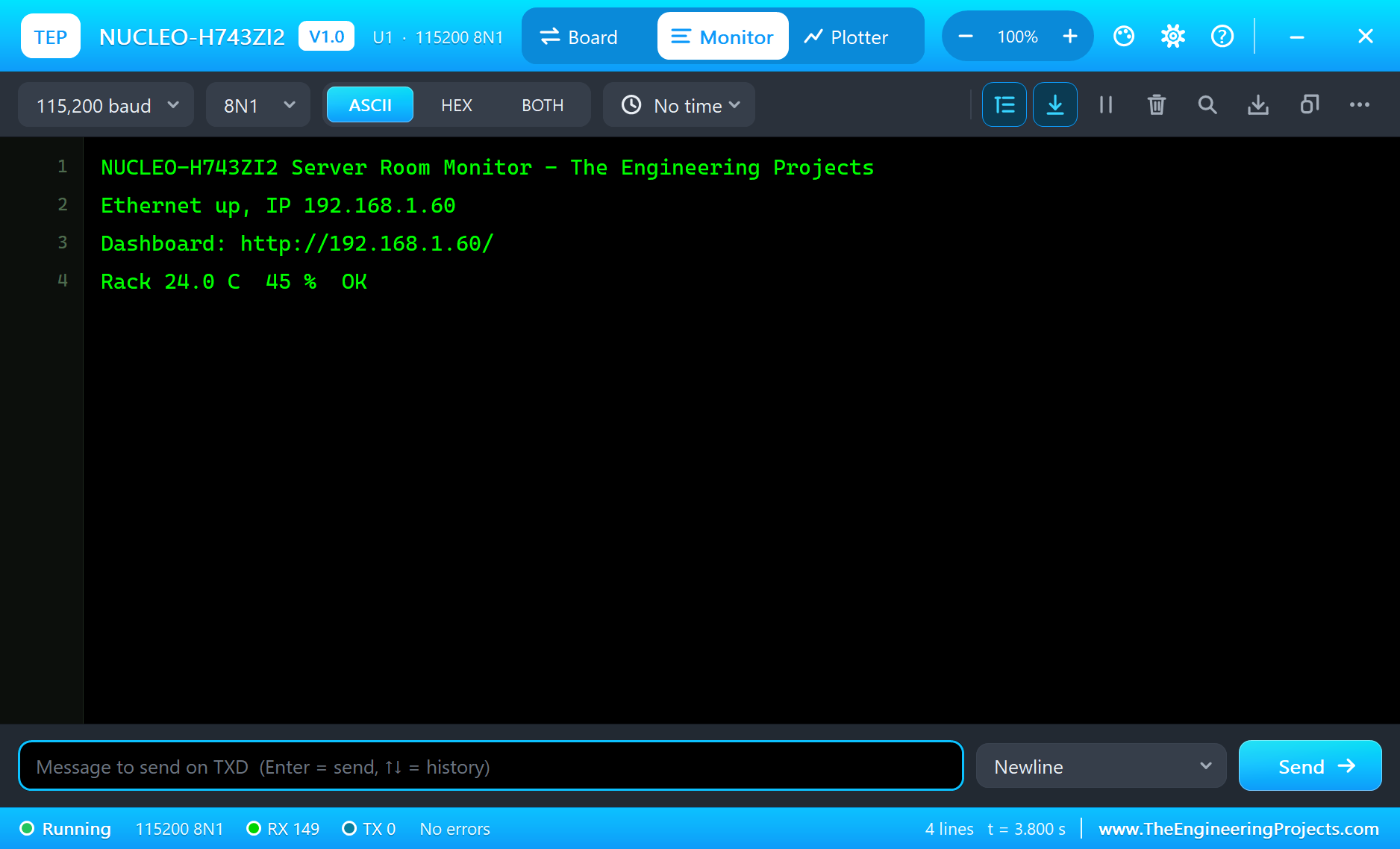
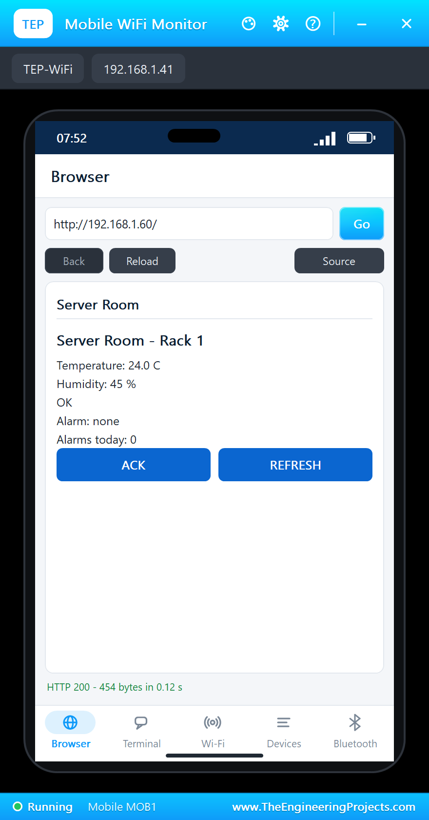
Open the Dashboard
Click the phone and press Go: the browser opens http://192.168.1.60/, served by the board over its Ethernet cable:
A Warm Rack
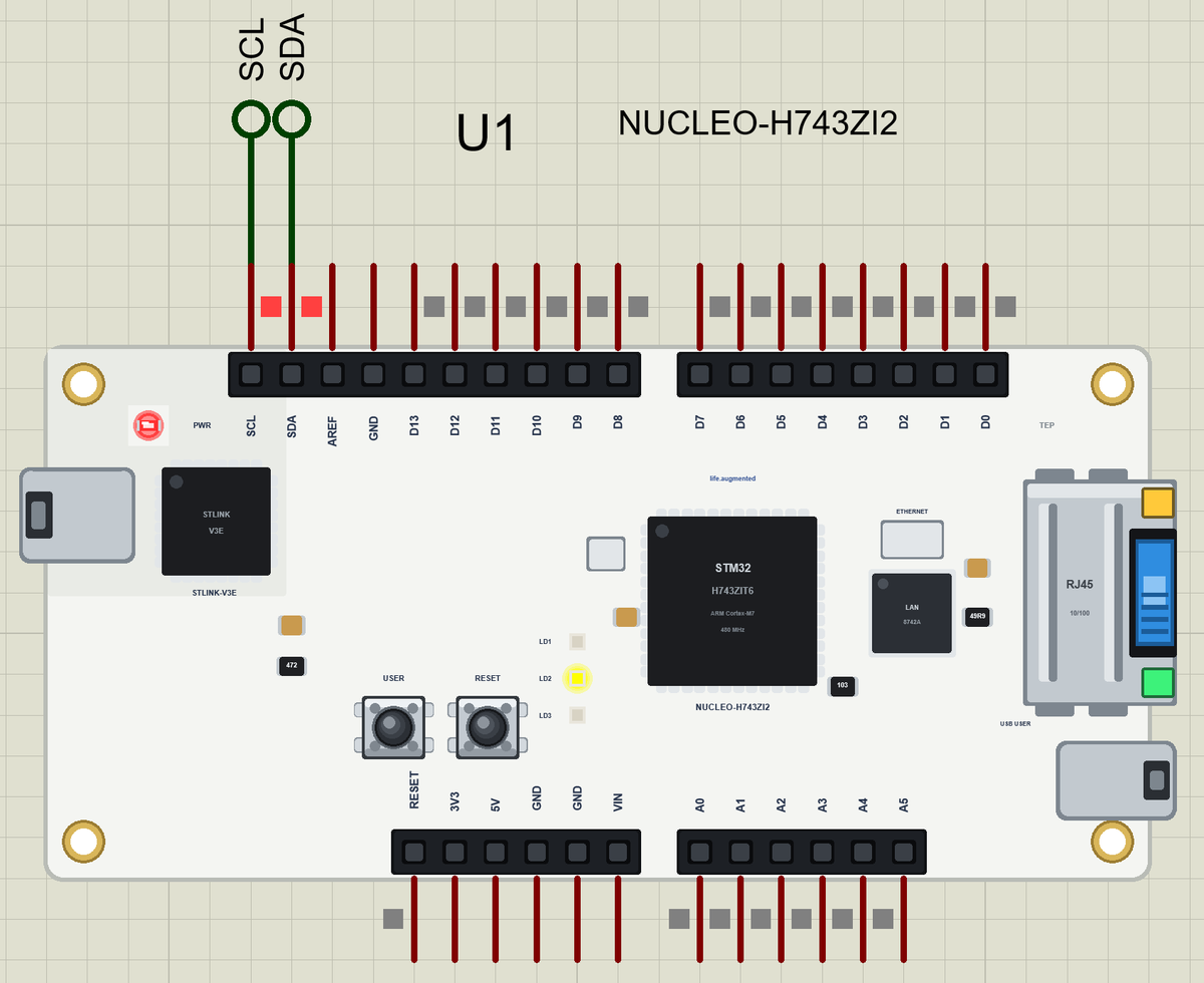
In the BME280's window, click the temperature track at about 30 C. The board prints the new level and LD2 lights yellow:
The Alarm
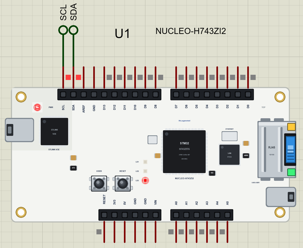
Now click the track at about 32.5 C. The rack is HOT, LD3 lights red and the alarm starts:
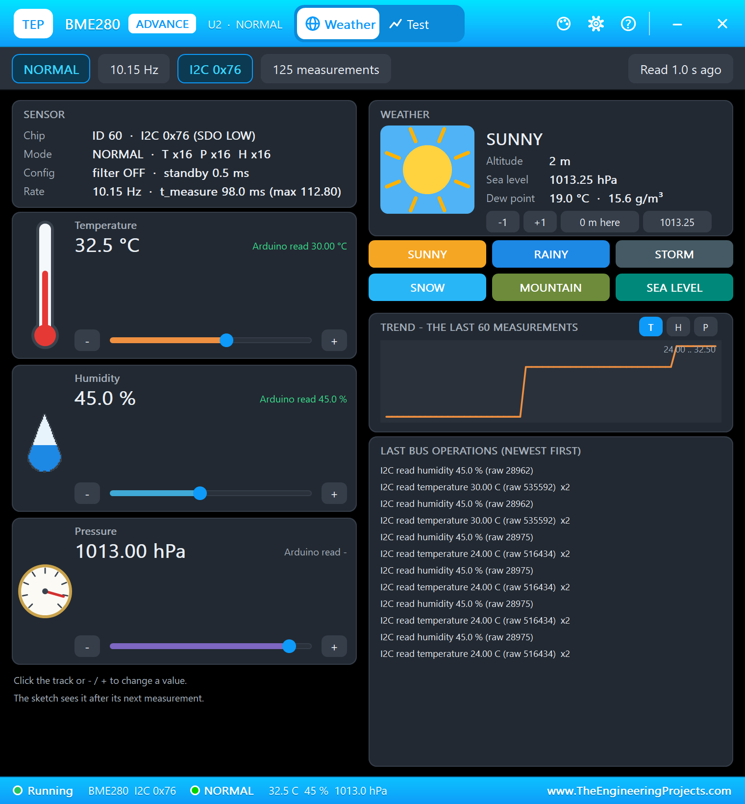
Here is the complete circuit while the simulation runs:
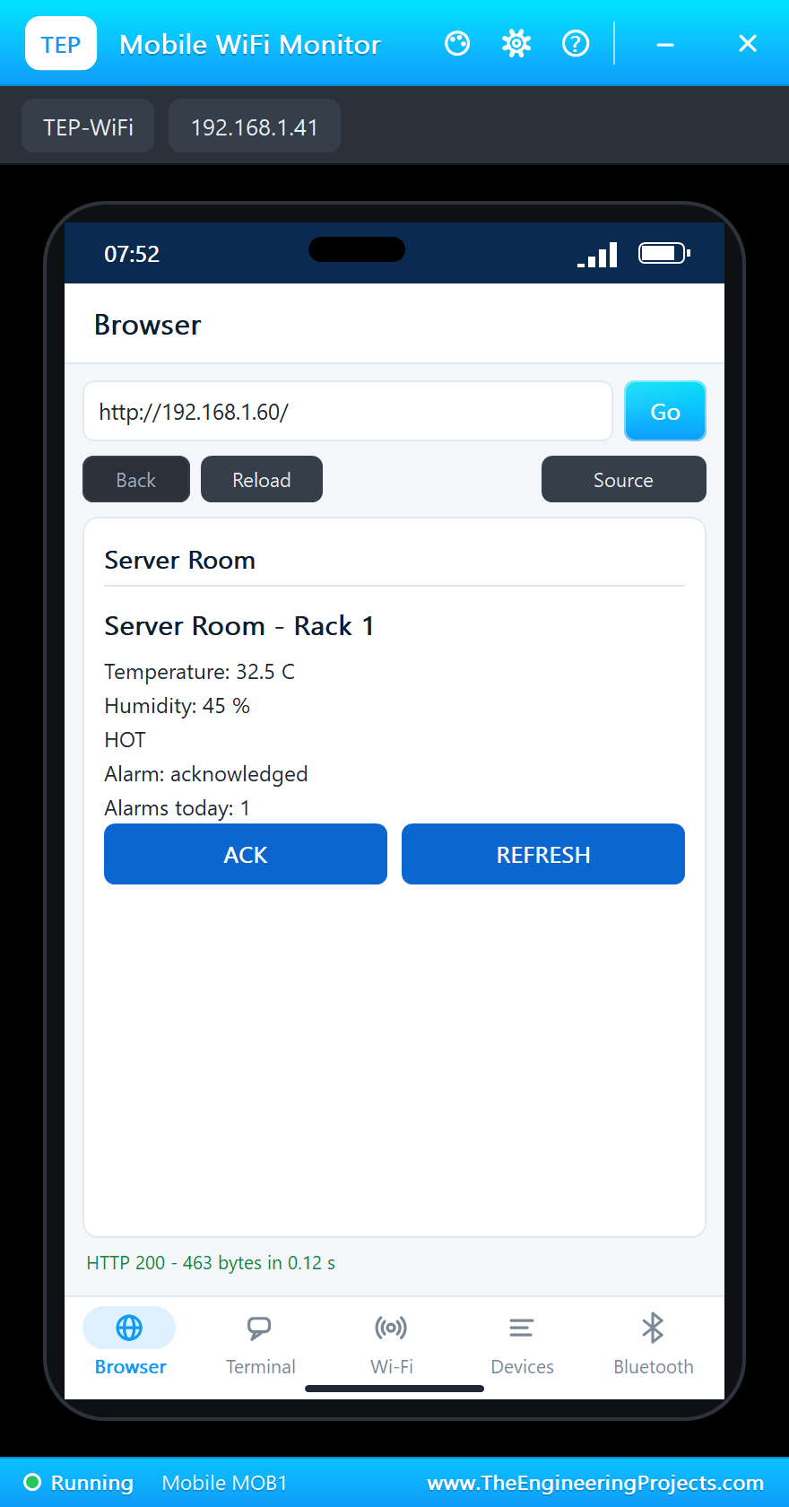
Press Reload on the phone: the dashboard shows the alarm. Then click USER on the board:
>> Level WARM, 30.0 C
Rack 30.0 C  45 %  WARM
>> ALARM: the rack is HOT, 32.5 C
Rack 32.5 C  45 %  HOT  (ALARM)
>> Alarm acknowledged by the USER button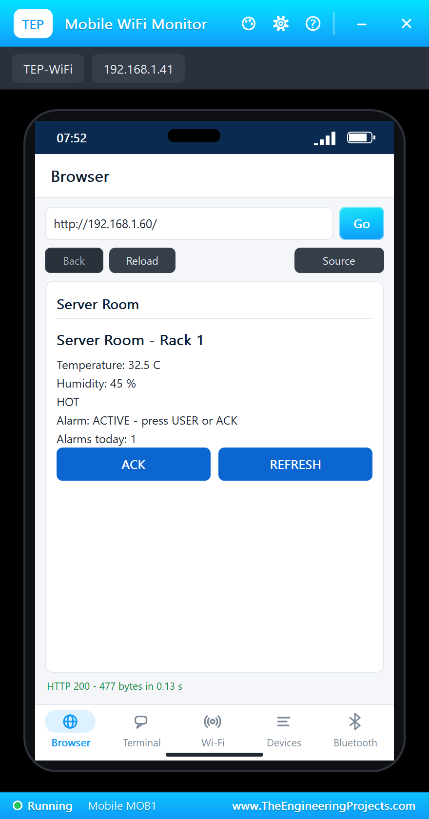
Acknowledge From the Phone
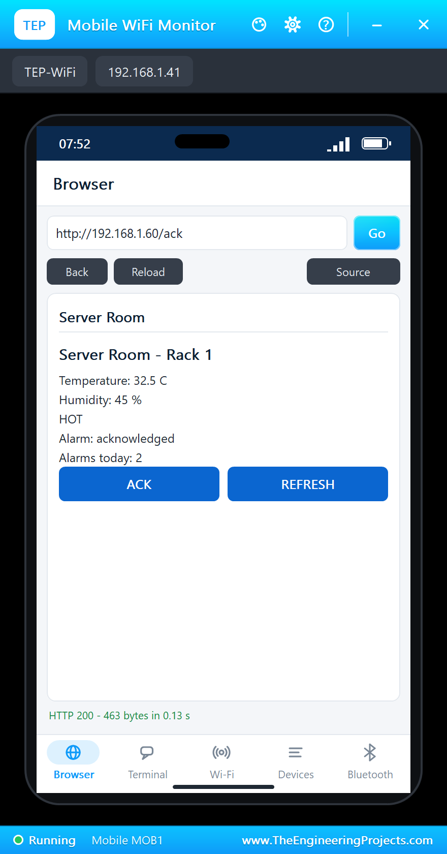
Click the track at about 25 C: the alarm is over and LD1 lights green again. Heat the rack once more, and this time tap ACK on the dashboard. The board acknowledges the alarm from the web page:
>> The alarm is over
>> Level OK, 25.0 C
Rack 25.0 C  45 %  OK
>> ALARM: the rack is HOT, 32.5 C
Rack 32.5 C  45 %  HOT  (ALARM)
>> Alarm acknowledged by the web page
>> The alarm is over
>> Level OK, 25.0 C
Rack 25.0 C  45 %  OK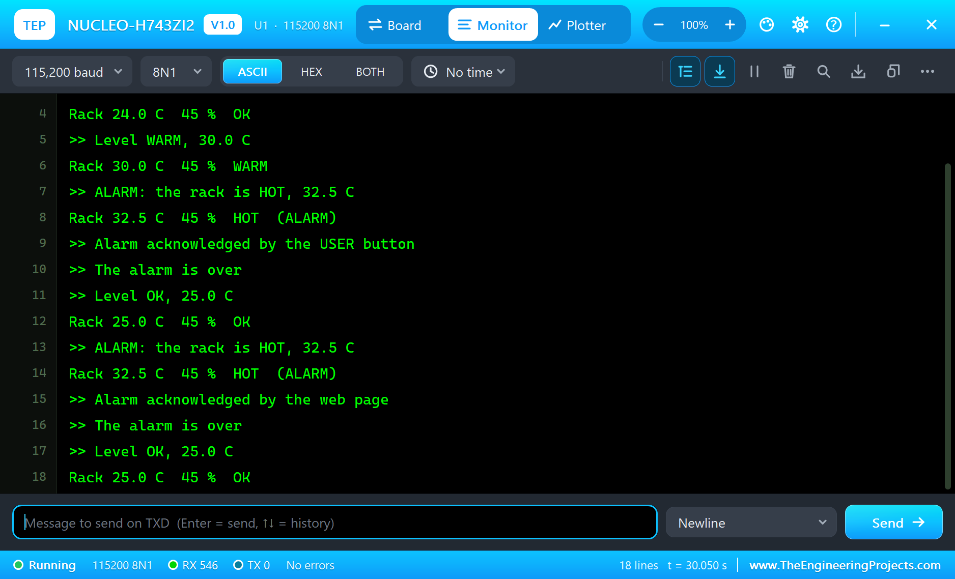
Pull the Cable
Click the RJ45 jack while the simulation runs: the plug comes out, the LINK LED goes dark and the board prints "Ethernet cable out!". Click it again and the dashboard is back. Set the property CABLE to OUT to start with the cable out, and the sketch prints "No Ethernet link - plug the cable in".
Where to Put the Sensor
Servers pull cool air in at the front and blow hot air out at the back. A sensor at the front measures what the servers get, which is what the limits of their makers refer to; a sensor at the back shows how hard they work. Mount the BME280 at the front, near the top of the rack, where the air is warmest, and keep it out of the direct stream of a fan.
Try It Yourself
- Change
WARM_CandHOT_Cto the limits of your own rack. - Blink LD3 while the alarm is not acknowledged, and keep it steady after USER.
- Use DHCP: replace
Ethernet.begin(ip)withEthernet.begin()and print the address the router gives. - Add the humidity to the levels: a rack that is too dry is a risk for static discharge.
Ideas to Extend the Monitor
- Send every alarm to a server with
EthernetClient, or to an MQTT broker. - Add a relay on D7 that starts an extra fan when the rack is WARM.
- Keep the highest temperature of the day and show it on the dashboard.
- Add a second BME280 at the top of the rack and compare the air in and out.
Your Own Sketches
Write the sketch in the Arduino IDE with the board ST NUCLEO-H743ZI2 (TEP Proteus), use Sketch > Export Compiled Binary and set the part's PROGRAM property to the .hex. Pick a fixed address in the router's range (192.168.1.x) or use DHCP.
Moving the Monitor to a Real NUCLEO-H743ZI2
- Install the STM32duino core in the Arduino IDE and select the board Nucleo-144, NUCLEO-H743ZI2.
- Install STM32duino LwIP and STM32duino STM32Ethernet from the Library Manager, and the two Adafruit libraries for the BME280.
- Connect a BME280 module to D14 (SDA), D15 (SCL), 3V3 and GND.
- Plug a network cable into the RJ45 jack and pick an address that is free on your network.
- Upload, open the Serial Monitor at 115200 and open the dashboard from a PC or phone on the same network.
The sketch is the same: the names of the LEDs and the button, the Ethernet calls and the web server move across without changes.
Things to Know Before Using a Real NUCLEO-H743ZI2
- 3.3 V logic: the Arduino headers are 3.3 V; most pins tolerate 5 V, but check a 5 V shield before you plug it in.
- Solder bridges: some header pins share signals with the Ethernet port; the board's user manual lists them.
- The USER button: it reads HIGH when pressed, the opposite of many other boards.
- A fixed address: make sure no other device uses it, or reserve it in the router.
Properties of the NUCLEO-H743ZI2
| Property | What it does |
|---|---|
| PROGRAM | the sketch: a .hex from TEP Boards for Proteus (board "ST NUCLEO-H743ZI2") |
| MONITOR, BAUD, AUTOOPEN | the built-in serial monitor: on, its baud rate (115200), open at Run |
| CABLE | the Ethernet cable at Run: IN or OUT |
Troubleshooting
- The phone shows nothing: press Go after "Dashboard:" is printed; the sketch must call
server.begin(). - "No Ethernet link": the cable is out - click the RJ45 jack, or set CABLE to IN.
- DHCP gives no address: use a fixed one in the router's range, as the demo does.
- The button seems dead: USER_BTN is HIGH while pressed - test for HIGH, not LOW.
- A number goes wrong above 32767: int is 16 bits in the simulation - use long.
Limitations of the Simulation
- Ethernet is IPv4, TCP and UDP to the TEP network of one simulation; the MAC address you pass is not used.
- The other Zio and the morpho headers are left out, and the user USB is drawn, not modelled.
- Your sketch gets 8 KB of RAM in the simulation, and int is 16 bits there.
- STM32, Nucleo and ST are names of STMicroelectronics and Arduino of Arduino; this library is not made or endorsed by them or by Labcenter.
- Tested in Proteus 8.5 in November 2026 (the demo as shipped, about 30 s of simulation). Proteus 7 is not supported.
So, that was all about the NUCLEO-H743ZI2 Library for Proteus. I hope it helps you try your Ethernet ideas on an STM32H7 in a simulation before you buy the board - the web pages, the alarms and the cable, all on one sheet. If you have any questions, ask in the comments and I will help you out. Till the next tutorial, take care and have fun!

Comments
0