


nRF52840 Dongle Library for Proteus: Bluetooth LE USB Simulation


Hello friends, I hope you all are doing great. Today, I am going to share the nRF52840 Dongle Library for Proteus, so you can run a Bluetooth LE simulation of Nordic Semiconductor's smallest nRF52840 board: a USB stick about the size of a thumb drive. The nRF52840 inside is an Arm Cortex-M4F with 1 MB of flash, 256 KB of RAM, Bluetooth LE, 802.15.4 for Thread and native USB. With this library the dongle runs your Arduino sketch in Proteus 8.5, lights its green and RGB LEDs, reads its button and talks to a phone over Bluetooth LE.
nRF52840 Dongle Library for Proteus
Latest version: V1.0 (November 2026, this tutorial)
Helping Tools
- Laptop WiFi Monitor: a laptop on the Wi-Fi of your design: a browser, a TCP / UDP terminal and ping
- Mobile WiFi Monitor: a smartphone that opens the pages of your board and sends it commands
- Serial Monitor Advance: a serial terminal window for the UART of your board
For the demo we built a Bluetooth busy light for an office door. The RGB LED shows FREE, BUSY, AWAY or DO NOT DISTURB, one click on the dongle's button moves to the next status, and a phone shows the status and how long it has lasted.
NOTICE: Proteus has no nRF52840 model, so our team has put a lot of effort into building this board ourselves: the LEDs, the button and Bluetooth LE are all our own model, and your sketch compiles with our free TEP Boards for Proteus add-on. Your feedback is the fuel that keeps us going, so please tell us what you think in the comments below. And if our free libraries help you, you can buy us a coffee. So, let's get started with the nRF52840 Dongle Library for Proteus:
What is the nRF52840 Dongle?
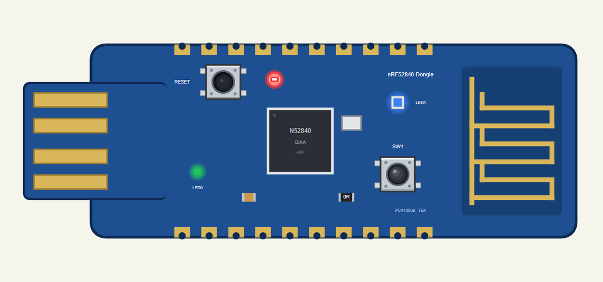
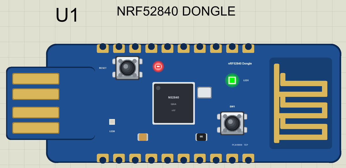
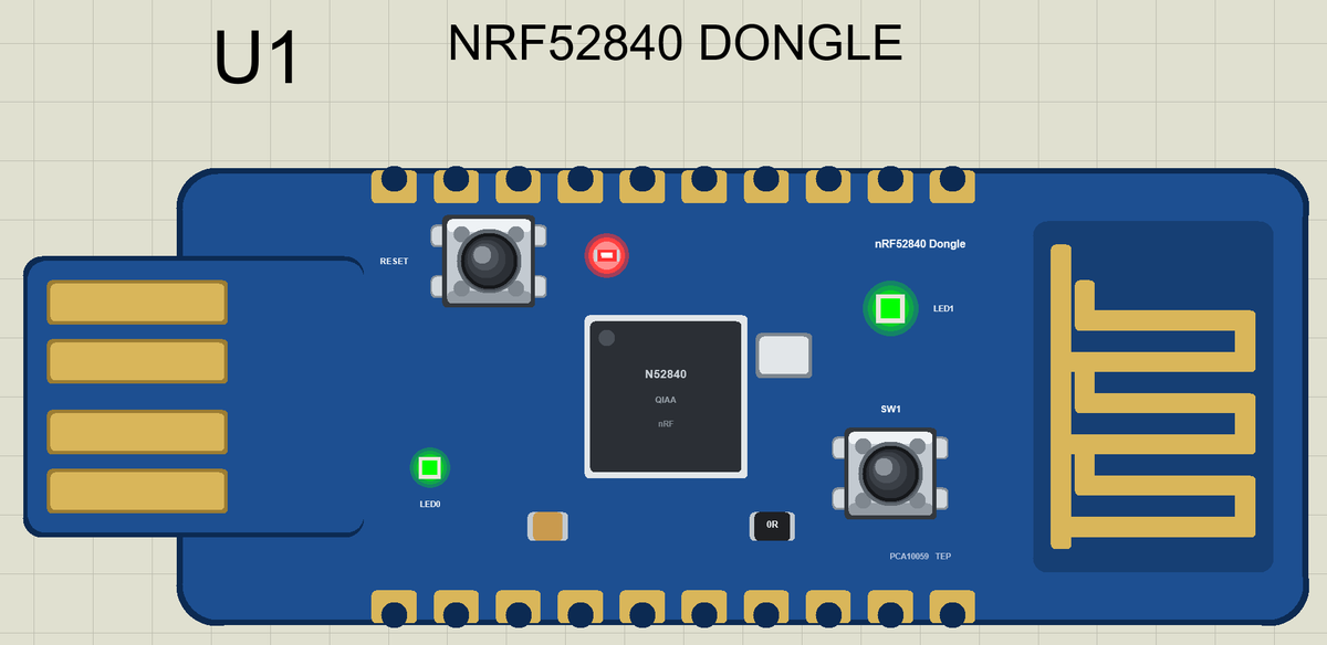
The nRF52840 Dongle (PCA10059) is Nordic Semiconductor's low-cost USB stick for the nRF52840. The PCB itself forms the USB-A plug, so it goes straight into a laptop without a cable. On the board are the nRF52840 with its crystal, a printed antenna at the far end, a green LED (LED0), an RGB LED (LED1), a user button (SW1), a small reset button on the side and castellated pads along the edges, so the stick can also be soldered onto another board.
| Part | The real nRF52840 Dongle | In the library |
|---|---|---|
| SoC | nRF52840: Cortex-M4F, 1 MB flash, 256 KB RAM | your Arduino sketch |
| Radio | Bluetooth LE, 802.15.4 (Thread, Zigbee) | ArduinoBLE |
| LED0 | green, P0.06, active LOW | LED0 |
| LED1 | RGB: red P0.08, green P1.09, blue P0.12, active LOW | LEDR, LEDG, LEDB |
| Buttons | SW1 on P1.06; RESET | SW1 (clickable), RESET |
| USB | the PCB plug, native USB on the chip | the serial monitor |
A Development Kit on a USB Stick
Nordic's big nRF52840 DK has a debugger, four buttons, four LEDs and Arduino headers; the dongle keeps only what fits on a stick. There is no debugger on board: the dongle comes with a USB bootloader, and you program it from the PC through its own USB plug. That makes it popular as a cheap second board next to the DK, as a Bluetooth sniffer, as a Thread or Zigbee radio for a gateway, or as the radio of a small product. For the full kit with its header, see our nRF52840 DK Library for Proteus.
One RGB LED, Many Statuses
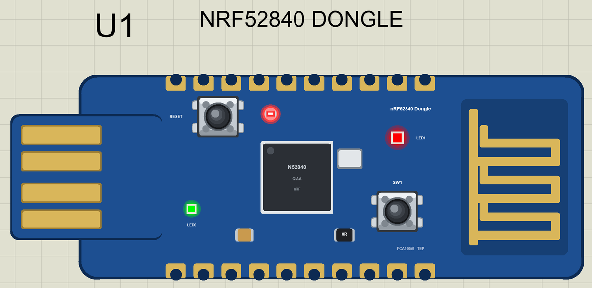
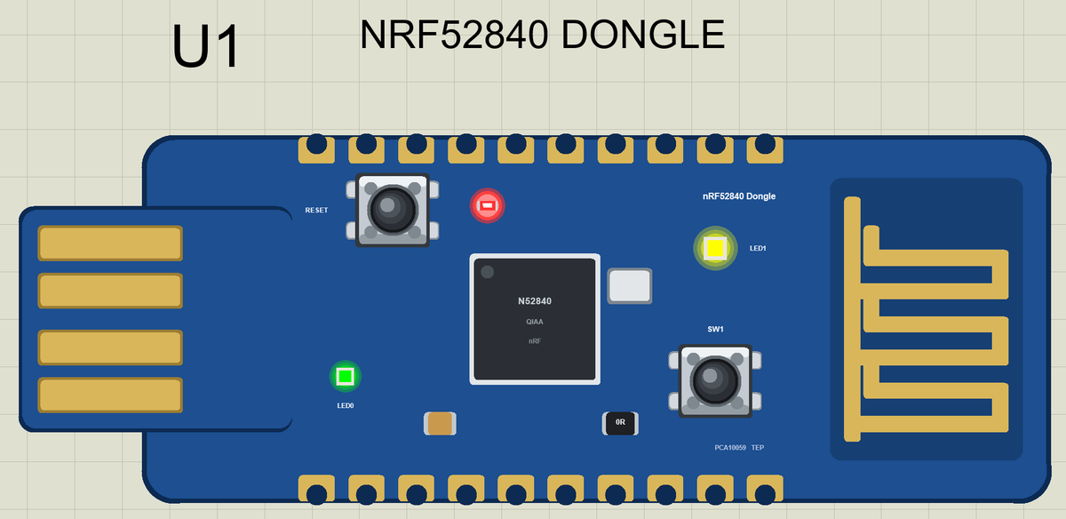
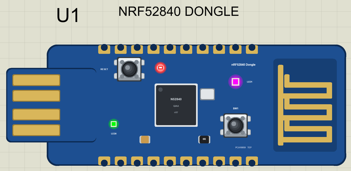
The RGB LED1 is really three LEDs in one package - red, green and blue - each on its own pin. Turning on two of them mixes a new colour: red and green make yellow, red and blue make purple, all three make white. On the dongle all of them light when the pin is LOW, so digitalWrite(LEDR, LOW) switches the red one on. Our demo uses five combinations for five statuses.
Bluetooth LE in a Few Words
The dongle is a Bluetooth LE peripheral: it advertises its name, a phone - the central - connects, and the dongle offers its data as characteristics grouped in services. Our busy light has three: the status, the seconds it has lasted and the number of changes. With notifications the phone sees every change at once, without asking again and again.
Where Is It Used?
Developers use the dongle as a Bluetooth LE sniffer with Wireshark, as the radio of a Thread border router, as a Zigbee coordinator, as a test central for their own products and as a tiny Bluetooth device in its own right - a presence beacon, a status light or a USB keyboard. Because it is so cheap, many labs keep a drawer of them.
A simulation lets you try the logic before the stick is in your laptop: the statuses, the colours, the button and the phone. When the sketch works in the Proteus simulation, the real dongle only has to confirm it.
Features of the nRF52840 Dongle Library for Proteus
- The board as it looks: the small blue stick with its USB-A plug, the nRF52840 and its crystal, the printed antenna, LED0, the RGB LED1, SW1, RESET and the edge pads, drawn compact, with our small TEP signature.
- Your sketch: a .hex for "Nordic nRF52840 Dongle (TEP Proteus)" with LED0, LEDR, LEDG, LEDB and SW1.
- Animated LEDs: the green LED0 and the RGB LED1 glow in the colour your sketch mixes.
- A button you click: SW1 works with the mouse while the simulation runs.
- Bluetooth LE: ArduinoBLE, with our phone as the central.
- A complete package: about 3.4 MB with the part, the add-on, the phone and the demo, without the source code of the models.
The nRF52840 Dongle in Proteus Simulation
Search NRF52840 in Pick Devices; the device NRF52840 DONGLE is in TEPDONGLE52.LIB (Microprocessor ICs, Bluetooth Boards), with the prefix U. The dongle has no pin header, so there is nothing to wire: drop it on the sheet, set its PROGRAM and press Run. A click on the USB plug opens the serial monitor.
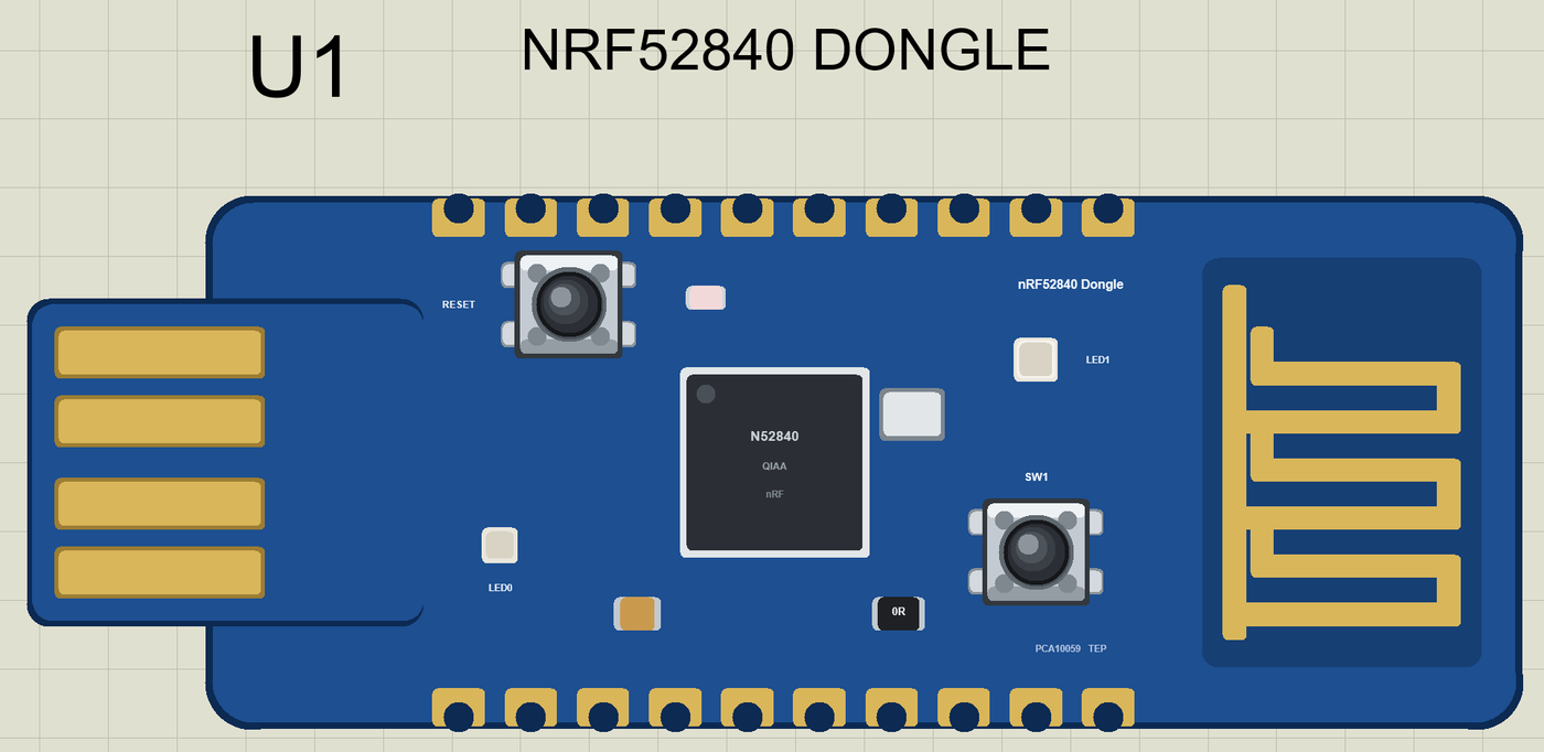
The LEDs and the Button
| Name | Number | The real dongle | What it does |
|---|---|---|---|
| LED0 | 0 | P0.06 | the green LED, lit when LOW; LED_BUILTIN |
| LEDR | 1 | P0.08 | the red part of LED1, lit when LOW |
| LEDG | 2 | P1.09 | the green part of LED1, lit when LOW |
| LEDB | 3 | P0.12 | the blue part of LED1, lit when LOW |
| SW1 | 4 | P1.06 | the user button, LOW when pressed; BTN_BUILTIN |
| RESET | - | P0.18 | restarts the sketch |
The numbers come from Zephyr's board files for the dongle, which list the LEDs and the button. Serial is the USB plug: the dongle's built-in monitor.
Download nRF52840 Dongle Library for Proteus
Click the button below to download nRF52840-Dongle-Library-for-Proteus-v1.0.zip (about 3.4 MB, without the source code of the models):
nRF52840 Dongle Library for Proteus V1.0- README.txt: installation, the demo, the pins, the properties, troubleshooting and the limits.
- Proteus Library Files:
TEPDONGLE52.LIBand the phone and laptop (TEPMOBILE.LIB,TEPLAPTOP.LIB). - Proteus Model Files:
TEPNET.DLL. - Arduino Code: the demo sketch and the TEP Boards for Proteus add-on 1.83.0, with ArduinoBLE.
- Proteus Simulation: the demo project, its HEX file and a copy of the DLL.
No Proteus yet? Read How to Download and Install Proteus 7 and 8. New to libraries? Follow How to Install a New Library in Proteus.
How to Install nRF52840 Dongle Library for Proteus
- Close Proteus and extract the whole zip file, for example to your Desktop.
- Copy the files from Proteus Library Files into the LIBRARY folder of Proteus.
- Copy
TEPNET.DLLfrom Proteus Model Files into the MODELS folder, replacing an older one. - Delete
TEPDONGLE52.IDXfrom the LIBRARY folder if it is there. - For your own sketches, copy Arduino Code\TEP Boards for Proteus\hardware into your Arduino sketchbook (Documents\Arduino) and restart the Arduino IDE; the board is Nordic nRF52840 Dongle (TEP Proteus).
- Start Proteus, press P and search for NRF52840.
Demo: a Bluetooth Busy Light in Simulation
A busy light tells colleagues at a glance whether you can be disturbed. Many are USB devices that sit on the monitor or hang on the door. Ours uses the dongle's RGB LED for the status and its button to change it, and Bluetooth LE lets a phone check the status from anywhere in the room.
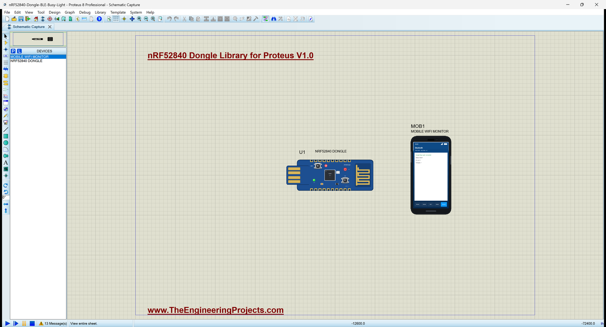
Open nRF52840-Dongle-BLE-Busy-Light.pdsprj. U1 runs Dongle_Busy_Light.hex; MOB1 is our Mobile WiFi Monitor, the phone.
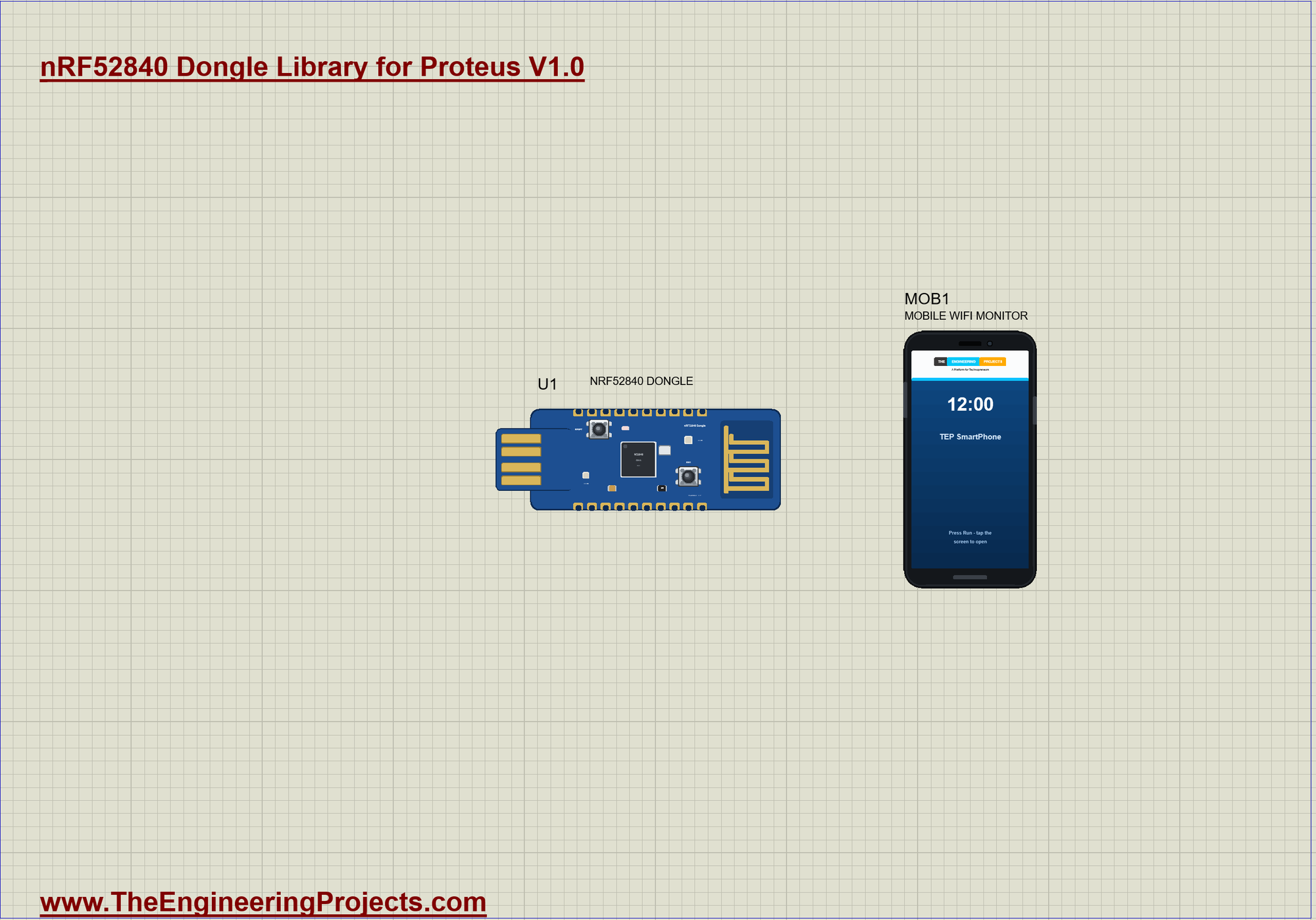
| Status | LED1 | Red, green, blue |
|---|---|---|
| FREE | green | off, on, off |
| BUSY | red | on, off, off |
| AWAY | yellow | on, on, off |
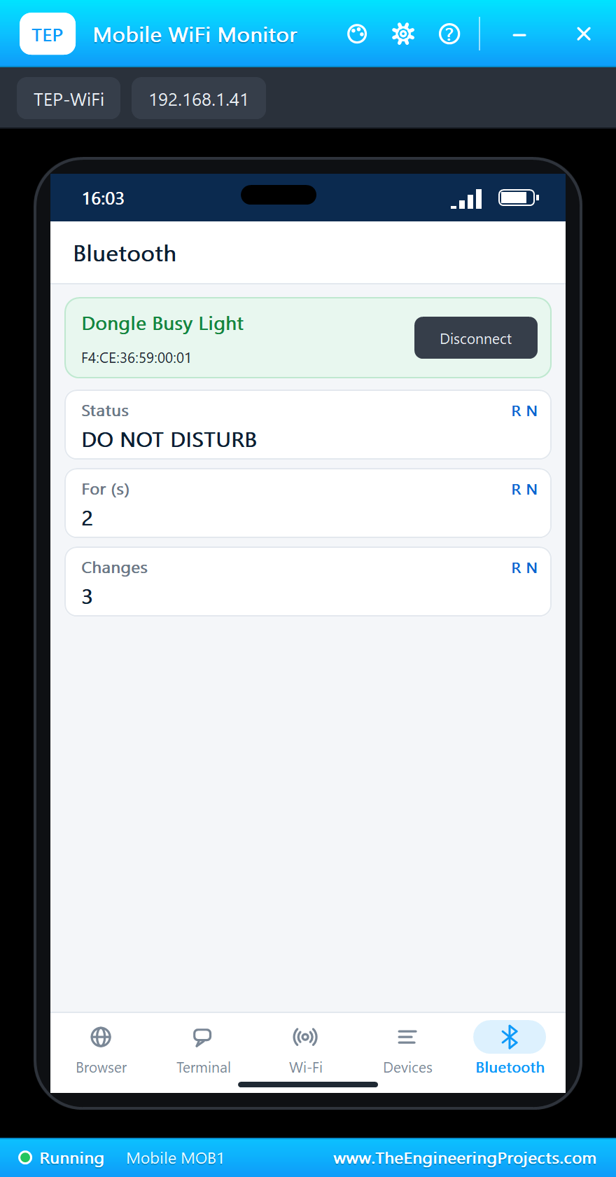
| DO NOT DISTURB | purple | on, off, on |
| OFF | dark | off, off, off |
The Status Table
Each status is a name and three flags for the red, green and blue LEDs. Keeping them in one table means a new status is one more line, and the rest of the sketch does not change:
struct Status { const char *name; bool r, g, b; };
const Status STATUSES[] = {{"FREE", 0, 1, 0}, {"BUSY", 1, 0, 0}, {"AWAY", 1, 1, 0}, {"DO NOT DISTURB", 1, 0, 1}, {"OFF", 0, 0, 0}};
const byte N_STATUSES = sizeof(STATUSES) / sizeof(STATUSES[0]);
Mixing the Colour
showStatus() writes the three LEDs. Because they light when LOW, a flag of 1 becomes LOW:
void showStatus() {
  const Status &s = STATUSES[status];
  digitalWrite(LEDR, s.r ? LOW : HIGH);                     // LOW = on
  digitalWrite(LEDG, s.g ? LOW : HIGH);
  digitalWrite(LEDB, s.b ? LOW : HIGH);
}
Changing the Status
setStatus() remembers how long the last status lasted, switches to the new one, updates the three characteristics and prints the change:
void setStatus(byte k) {
  const unsigned long held = (millis() - since) / 1000;
  status = k;
  since = millis();
  changes++;
  showStatus();
  statusChar.writeValue(STATUSES[k].name);
  sinceChar.writeValue(0);
  changesChar.writeValue(changes);
  Serial.print(F(">> ")); Serial.print(STATUSES[k].name); Serial.print(F(" (the last status lasted "));
  Serial.print(held); Serial.println(F(" s)"));
}
The Loop
The loop keeps Bluetooth running, lights LED0 while a phone is connected, steps to the next status on each press of SW1 and sends the seconds of the current status once a second:
void loop() {
  BLE.poll();
  const bool connected = BLE.connected();
  if (connected != wasConnected) {
    wasConnected = connected;
    digitalWrite(LED0, connected ? LOW : HIGH);             // LED0: the phone is connected
    Serial.println(connected ? F("Phone connected") : F("Phone disconnected"));
  }
  const bool now = digitalRead(SW1);
  if (now != lastSw1) {
    lastSw1 = now;
    if (now == LOW) setStatus((status + 1) % N_STATUSES);   // act on the press
  }
  if (millis() >= nextSecond) { nextSecond = millis() + 1000; sinceChar.writeValue((int)((millis() - since) / 1000)); }
}
The Bluetooth Service
Three characteristics carry the status, the seconds and the changes, each with a readable 0x2901 name for the phone:
BLEService lightService("19B10090-E8F2-537E-4F6C-D104768A1214");
BLEStringCharacteristic statusChar("19B10091-E8F2-537E-4F6C-D104768A1214", BLERead | BLENotify, 16);
BLEIntCharacteristic sinceChar("19B10092-E8F2-537E-4F6C-D104768A1214", BLERead | BLENotify);
BLEIntCharacteristic changesChar("19B10093-E8F2-537E-4F6C-D104768A1214", BLERead | BLENotify);
Run the Simulation
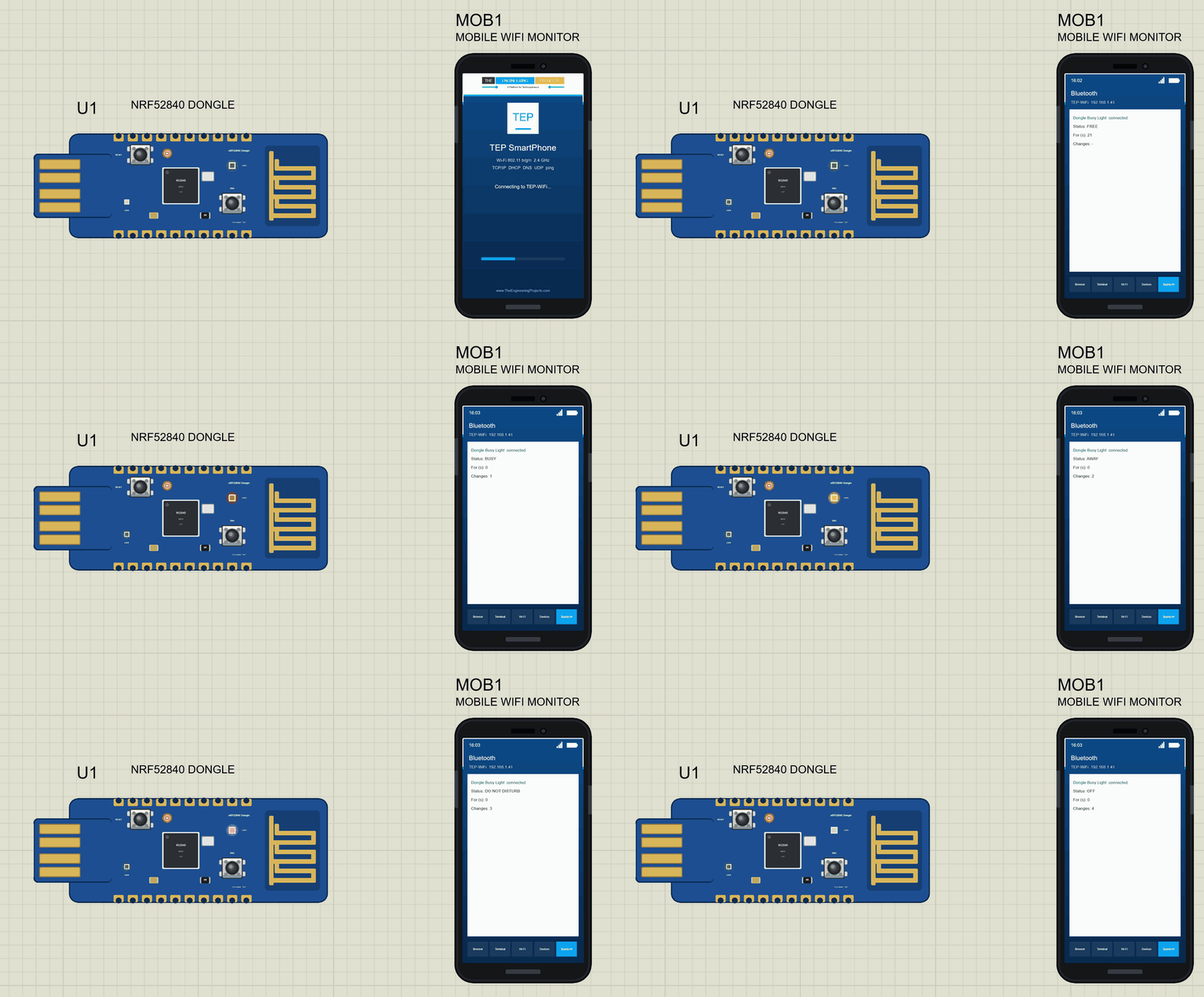
Press Run. The serial monitor - the same window as our TEP Serial Monitor Advance for Proteus - shows the name the dongle advertises and the first status, and LED1 turns green:
nRF52840 Dongle Bluetooth Busy Light - The Engineering Projects
Advertising as "Dongle Busy Light"   SW1 = the next status
>> FREE
Phone connected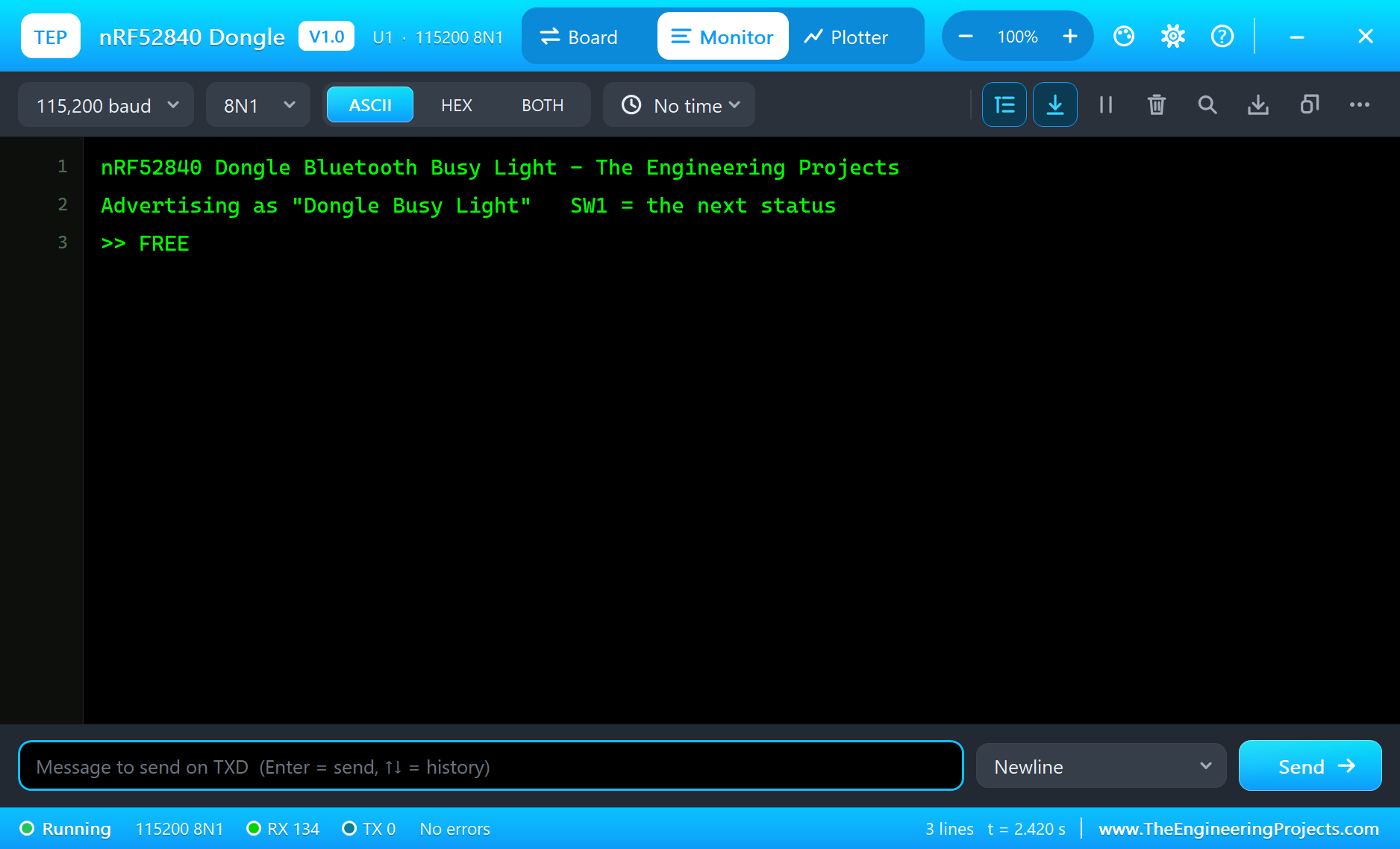
Connect the Phone
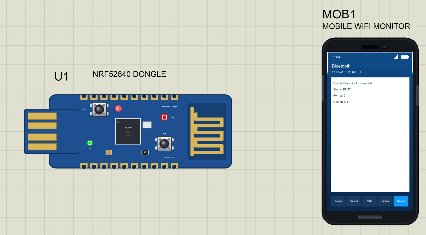
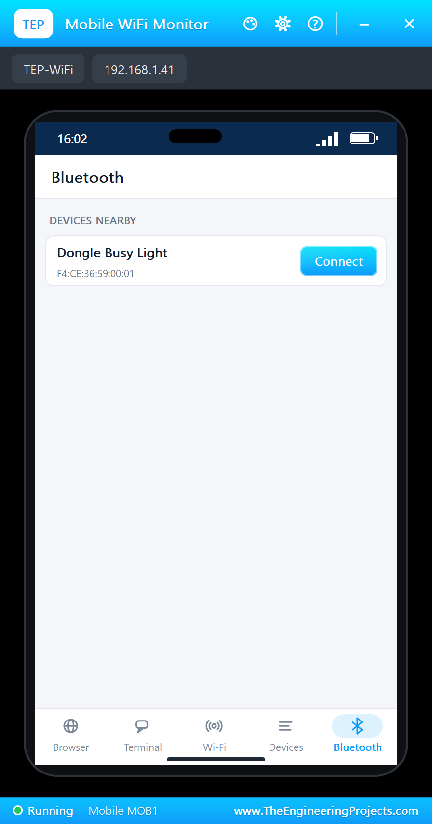
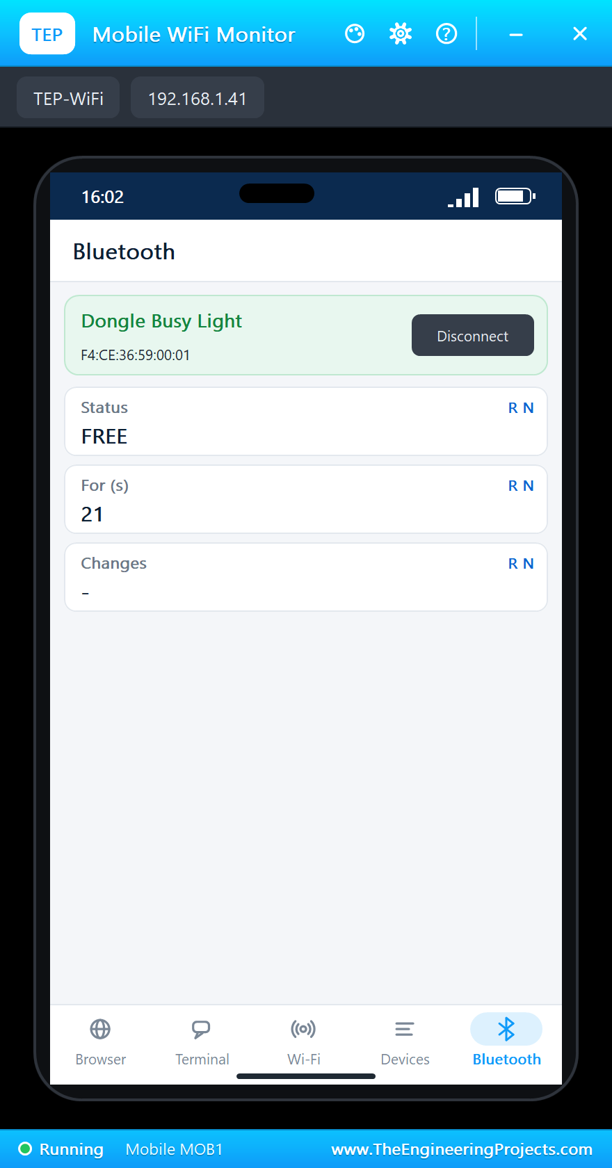
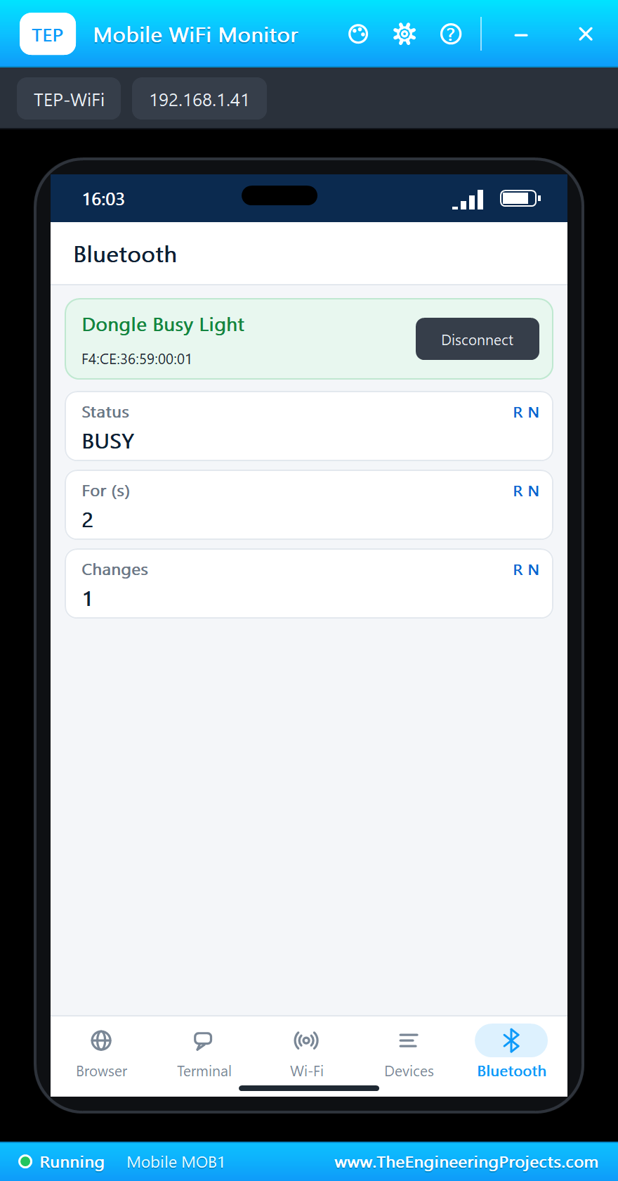
On the phone open the Bluetooth app and press SCAN; "Dongle Busy Light" appears in the list. Connect to it: the green LED0 lights and the phone shows the status, the seconds and the changes:
Busy
Click SW1 on the dongle: BUSY, LED1 turns red, and the phone gets the change at once. Here is the complete circuit while the simulation runs:
Away and Do Not Disturb
Click SW1 again: AWAY, red and green together make yellow. Once more: DO NOT DISTURB, red and blue make purple:
Off
One more click switches the light OFF, and the next one starts again at FREE. Every change is printed with how long the last status lasted:
>> BUSY (the last status lasted 22 s)
>> AWAY (the last status lasted 3 s)
>> DO NOT DISTURB (the last status lasted 1 s)
>> OFF (the last status lasted 3 s)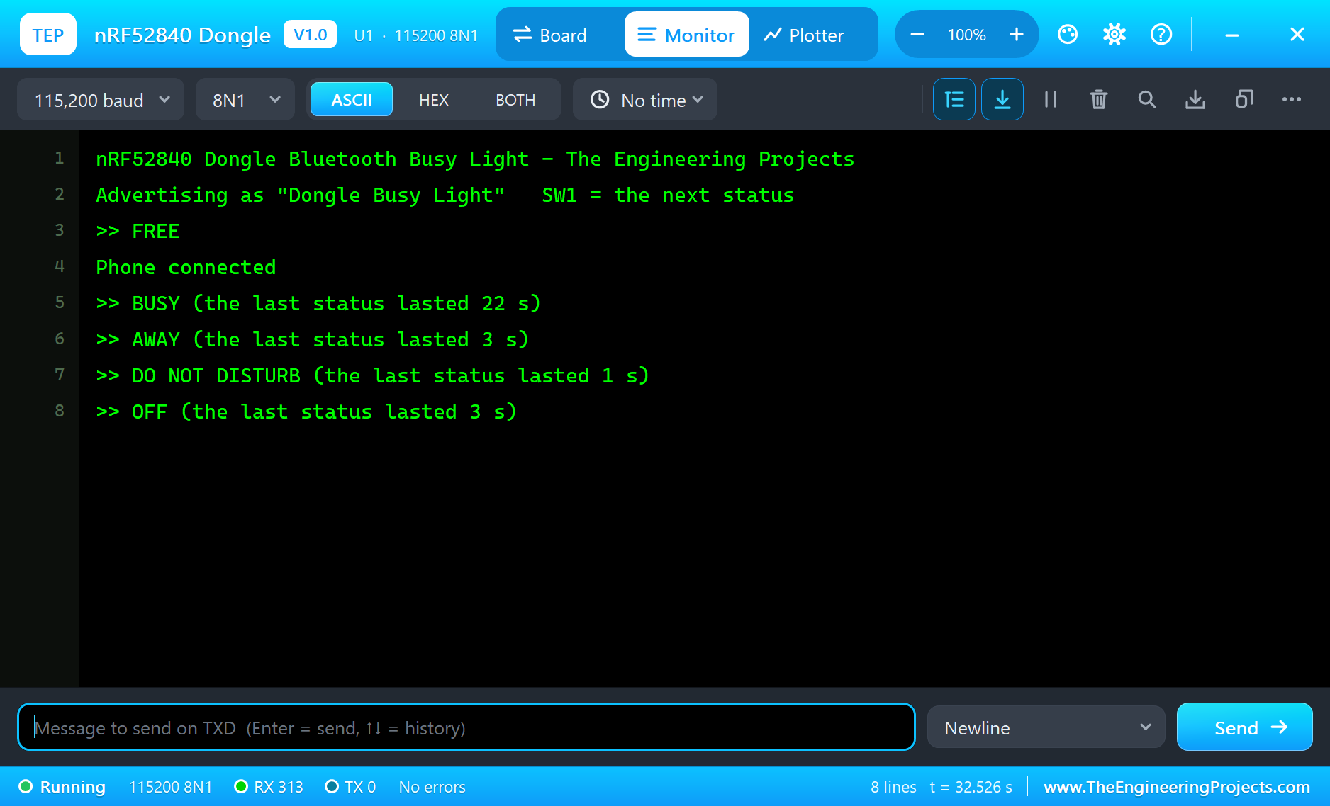
Why Act on the Press?
The loop compares the button with its last reading and acts only when it changes from HIGH to LOW - the moment of the press. If the sketch acted while the button was LOW, one long press would race through all five statuses. Real buttons also bounce: the contact opens and closes a few times in the first milliseconds. In the simulation the button is clean, but on the real dongle a short delay of 20 to 50 ms after a change, or a check that the reading is stable, keeps one press from counting twice.
Counting Seconds Without delay()
The sketch never calls delay(): Bluetooth needs BLE.poll() often, and a long delay would make the phone wait. Instead it compares millis() with the time of the next update. The same pattern runs any number of jobs side by side - here the button, the Bluetooth connection and the once-a-second counter.
Colours for People
Red, yellow and green are understood by everyone, but about one man in twelve sees red and green poorly. A good status light adds a second clue: a blinking pattern, a different brightness or a short text on the phone. That is why the phone in our demo shows the status as a word, not only as a colour.
Notifications Instead of Polling
The phone could ask the dongle for the status every second, but that wastes radio time and battery. With BLENotify the dongle tells the phone when something changes. The seconds counter sends one small notification a second; the status and the number of changes are sent only when they change.
Softer Colours with analogWrite
digitalWrite() gives each LED only on or off, so LED1 can show seven colours. With analogWrite() on LEDR, LEDG and LEDB every channel gets 256 steps, and LED1 can mix orange, pink or a calm white, or fade slowly between two statuses. Remember that the LEDs light when LOW: analogWrite(LEDR, 0) is full red and 255 is off. The library shows the mixed colour on the drawn LED while the simulation runs.
Why a USB Stick?
A device that lives in a USB port needs no battery and no extra cable: the laptop powers it and talks to it at the same time. That is why the dongle form is popular for status lights, Bluetooth adapters, presentation clickers and test tools. On the real dongle the sketch could also show up as a USB device of its own; in our simulation the USB plug is the serial monitor.
The USB Bootloader
The real dongle has no debugger. Hold the reset button sideways and it starts its bootloader, the red LED pulses, and Nordic's tools load a new program over the USB plug. In our simulation the PROGRAM property takes the place of that: set it to the .hex and press Run. The RESET button on the drawn stick restarts the sketch.
Try It Yourself
- Blink LED1 slowly at DO NOT DISTURB so it is noticed from far away.
- Use analogWrite to dim the LEDs at night.
- Add a long press of SW1 that jumps straight back to FREE.
- Switch to AWAY by itself when the phone disconnects.
Ideas to Extend the Busy Light
- Let the phone write the status with a writable characteristic.
- Add a "back in 10 minutes" status with a countdown.
- Count how many minutes a day were BUSY.
- Use several dongles, one per desk, with the same service.
Your Own Sketches
Write the sketch in the Arduino IDE with the board Nordic nRF52840 Dongle (TEP Proteus), use Sketch > Export Compiled Binary and set the part's PROGRAM property to the .hex.
Moving to a Real nRF52840 Dongle
- Install Nordic's nRF Connect SDK, or Zephyr with the board nrf52840dongle/nrf52840.
- Start from Nordic's Bluetooth peripheral samples and the LED and button samples.
- Move the logic of the demo across: the status table, the colours, the button and the service.
- Put the dongle in its bootloader with the reset button and program it over USB.
- Test with a phone app such as nRF Connect for Mobile.
The statuses, the colours and the Bluetooth service stay the same; on the real dongle Nordic's SDK takes the place of the Arduino calls. For a kit with more LEDs, four buttons and an Arduino header, see our nRF52833 DK Library for Proteus.
Things to Know Before Using a Real nRF52840 Dongle
- No debugger: programs go in through the USB bootloader; a mistake in the USB code can need the reset button.
- 3.3 V or lower: the edge pads run at the chip's voltage; 5 V signals need a level shifter.
- Power: the dongle runs from the USB plug, or from a supply on its edge pads when it is soldered onto a board.
- Thread and Zigbee: the 802.15.4 radio works with Nordic's SDK, not in the simulation.
Properties of the nRF52840 Dongle
| Property | What it does |
|---|---|
| PROGRAM | the sketch: a .hex from TEP Boards for Proteus (board "Nordic nRF52840 Dongle") |
| MONITOR, BAUD, AUTOOPEN | the built-in serial monitor: on, its baud rate (115200), open at Run |
Troubleshooting
- The phone finds nothing: call
BLE.begin(), set a local name andBLE.advertise(); callBLE.poll()in loop(). - SW1 does nothing: use
pinMode(SW1, INPUT_PULLUP)and act whendigitalRead()is LOW. - The LEDs look inverted: they light when the pin is LOW, as on the real dongle.
- A colour looks wrong: yellow is red plus green, purple is red plus blue.
- A number goes wrong above 32767: int is 16 bits in the simulation - use long.
Limitations of the Simulation
- Bluetooth LE: the dongle is a peripheral only, with one phone as the central.
- The edge pads, 802.15.4 / Thread, USB device classes and the bootloader are drawn, not modelled.
- Your sketch gets 8 KB of RAM in the simulation, and int is 16 bits there.
- nRF52840 and Nordic Semiconductor are names of Nordic Semiconductor ASA and Arduino of Arduino, and the Bluetooth word mark belongs to Bluetooth SIG; this library is not made or endorsed by them or by Labcenter.
- Tested in Proteus 8.5 in November 2026 (the demo as shipped, about 33 s of simulation). Proteus 7 is not supported.
So, that was all about the nRF52840 Dongle Library for Proteus. I hope it helps you try your Bluetooth ideas in a simulation before the stick goes into your laptop - the RGB LED, the button and the phone, all on one sheet. If you have any questions, ask in the comments and I will help you out. Till the next tutorial, take care and have fun!

Comments
0