


nRF54LM20 DK Library for Proteus: nRF54LM20 Bluetooth LE Simulation


Hello friends, I hope you all are doing great. Today, I am going to share the nRF54LM20 DK Library for Proteus, so you can run a Bluetooth LE simulation of Nordic Semiconductor's nRF54LM20 development kit. The nRF54LM20 is a member of the new nRF54L series: an Arm Cortex-M33 with a RISC-V coprocessor, Bluetooth LE, 802.15.4 for Thread and high-speed USB, with many GPIOs for bigger designs. With this library the kit runs your Arduino sketch in Proteus 8.5, uses its GPIO headers for sensors, lights its LEDs, reads its buttons and talks to a phone over Bluetooth LE.
nRF54LM20 DK Library for Proteus
Latest version: V1.0 (November 2026, this tutorial)
Helping Tools
- Laptop WiFi Monitor: a laptop on the Wi-Fi of your design: a browser, a TCP / UDP terminal and ping
- Mobile WiFi Monitor: a smartphone that opens the pages of your board and sends it commands
- Serial Monitor Advance: a serial terminal window for the UART of your board
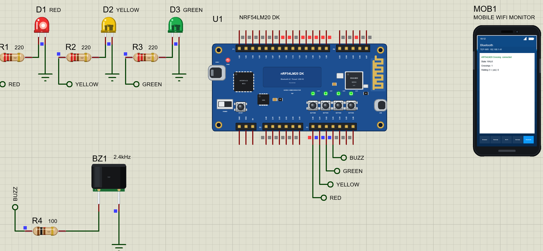
For the demo we built a Bluetooth pedestrian crossing. Three 5 mm LEDs are the cars' traffic light, the kit's BUTTON0 is the pedestrians' request, its four LEDs count the walk time down while a buzzer ticks, and a phone follows every step.
NOTICE: Proteus has no nRF54LM20 model, so our team has put a lot of effort into building this board ourselves: the GPIOs, the LEDs, the buttons and Bluetooth LE are all our own model, and your sketch compiles with our free TEP Boards for Proteus add-on. Your feedback is the fuel that keeps us going, so please tell us what you think in the comments below. And if our free libraries help you, you can buy us a coffee. So, let's get started with the nRF54LM20 DK Library for Proteus:
What is the nRF54LM20 DK?
The nRF54LM20 DK (PCA10184) is Nordic Semiconductor's development kit for the nRF54LM20. The "M" chips of the nRF54L series add more memory, more GPIOs and a high-speed USB port to the line, for products such as keyboards, mice, game controllers and gateways. The kit carries the chip with its antenna, an interface MCU that programs and debugs it over USB, the chip's own USB port, an external SPI flash, four buttons, four green LEDs and pin headers for its GPIO ports.
| Part | The real nRF54LM20 DK | In the library |
|---|---|---|
| SoC | nRF54LM20: Cortex-M33 with a RISC-V coprocessor | your Arduino sketch |
| Radio | Bluetooth LE, 802.15.4 (Thread) | ArduinoBLE |
| LEDs | LED0 to LED3 on P1.22, P1.25, P1.27, P1.28, active HIGH | LED0 to LED3 |
| Buttons | BUTTON0 to BUTTON3 on P1.26, P1.09, P1.08, P0.05 | BUTTON0 to BUTTON3 |
| Headers | GPIO ports P0 to P3 | 32 GPIOs by their port names |
| USB | interface MCU; high-speed USB on the chip | the serial monitor; drawn |
A Kit Without an Arduino Header
Like the other nRF54L kits, the nRF54LM20 DK does not copy the Arduino Uno layout. Its GPIOs come out on headers grouped by port, and the pins are named after the chip's ports: P1.04, P2.01, P3.00 and so on. Our library does the same: the part's pins carry those names, and in your sketch you write P3_00 for P3.00. The 32 GPIOs are the ones Zephyr's board files for the kit describe: the expansion header, the LEDs, the buttons and the UART30 port.
Buttons and LEDs on GPIOs
The LEDs and buttons are ordinary GPIOs on the headers, so they appear on the part as well. The LEDs light when the pin is HIGH and the buttons read LOW while pressed. Note the numbering: on the nRF54L kits Nordic counts from zero - LED0 to LED3, BUTTON0 to BUTTON3.
Our Choices for the Arduino Buses
Arduino sketches expect fixed pins for Serial1, I2C, SPI and the analog inputs. For Serial1 we use the kit's own UART30 pins, P0.06 for TX and P0.07 for RX. For the rest we picked pins from the expansion header: SDA and SCL on P1.02 and P1.03, A0 to A3 on P1.04 to P1.07, and SPI on P2.01, P2.02, P2.04 and P2.05. The README lists them all.
Where Is It Used?
The nRF54LM20 targets Bluetooth products with many inputs or a wired USB link: keyboards and mice, game controllers, remote controls, USB dongles and smart home hubs. Its high-speed USB port also makes it a good bridge between a PC and a Bluetooth or Thread network.
A simulation lets you try the whole design before the kit is on the desk: the sensor, the buttons, the LEDs and the Bluetooth service. When the sketch works in the Proteus simulation, the real kit only has to confirm it.
Features of the nRF54LM20 DK Library for Proteus
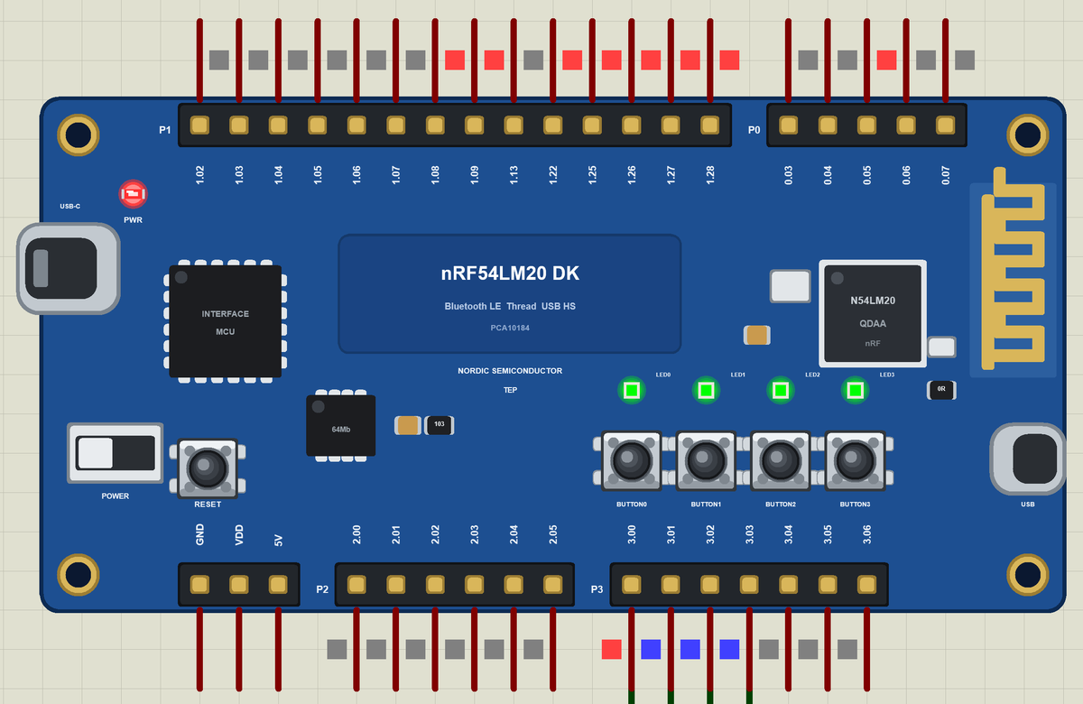
- The board as it looks: the blue kit with the nRF54LM20 and its antenna, the interface MCU with its USB-C port, the SoC's own USB port, the external flash, the power switch, RESET, the four buttons, the four LEDs and the P0 to P3 headers, drawn compact, with our small TEP signature.
- Your sketch: a .hex for "Nordic nRF54LM20 DK (TEP Proteus)" with the 32 GPIOs by name, LED0 to LED3 and BUTTON0 to BUTTON3.
- Sensors on the headers: digital I/O, analogRead, PWM, interrupts, pulse timing, Serial1, Wire and SPI.
- Bluetooth LE: ArduinoBLE, with our phone as the central.
- A complete package: about 4.4 MB with the part, the add-on, the LEDs, the buzzer, the resistors, the phone and the demo, without the source code of the models.
The nRF54LM20 DK in Proteus Simulation
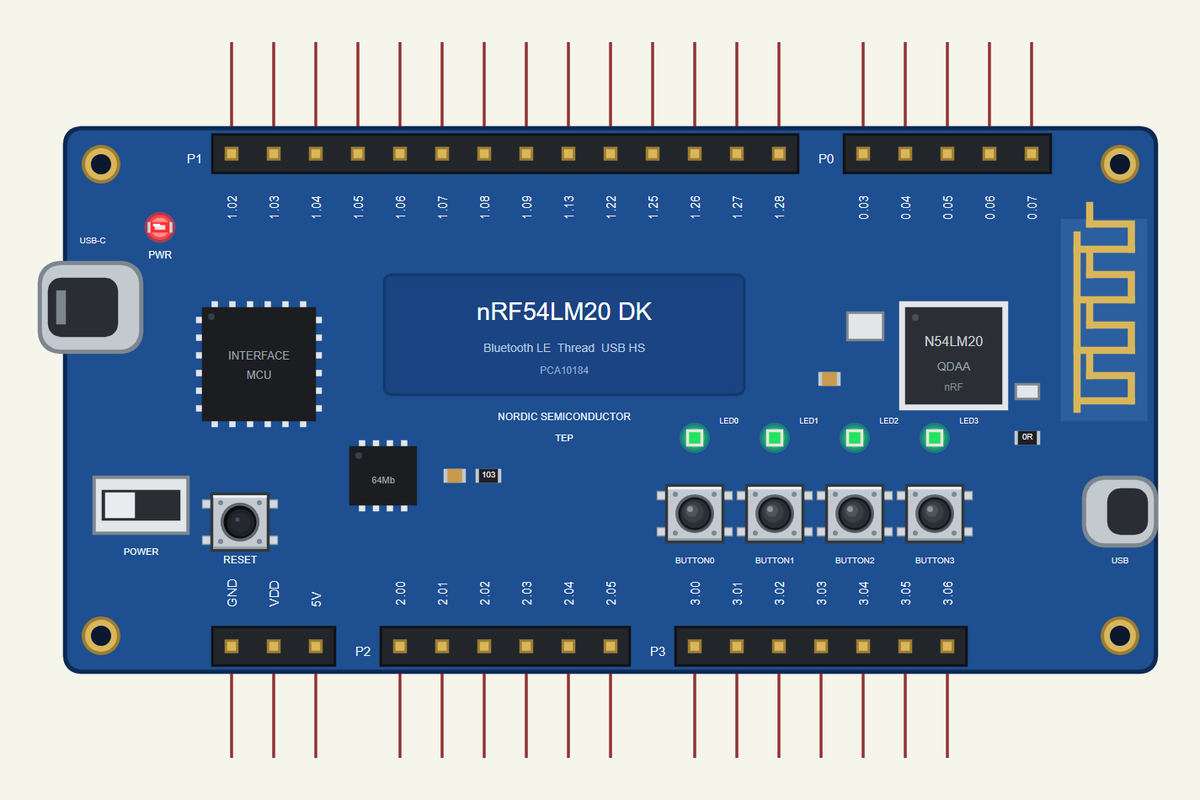
Search NRF54LM20 in Pick Devices; the device NRF54LM20 DK is in TEPNRF54LM20DK.LIB (Microprocessor ICs, Bluetooth Boards), with the prefix U. The USB-C port opens the serial monitor.
The Pins
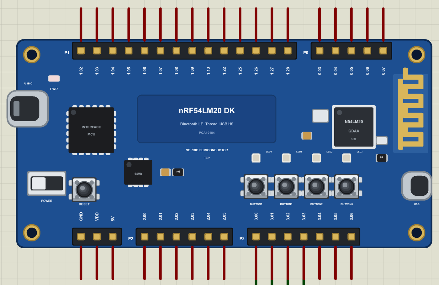
| Pins | What the library does with them |
|---|---|
| P0.03, P0.04, P1.13, P3.00 to P3.06 | GPIO, PWM, interrupt, pulse timing |
| P0.06, P0.07 | Serial1 TX and RX (the kit's UART30), or GPIO |
| P1.02, P1.03 | Wire SDA and SCL, or GPIO |
| P1.04 to P1.07 | A0 to A3: analogRead 0 to 1023, or GPIO |
| P2.00 to P2.05 | GPIO; SPI on P2.01, P2.02, P2.04, P2.05 |
| P1.22, P1.25, P1.27, P1.28 | LED0 to LED3, lit when HIGH |
| P1.26, P1.09, P1.08, P0.05 | BUTTON0 to BUTTON3, LOW when pressed |
Download nRF54LM20 DK Library for Proteus
Click the button below to download nRF54LM20-DK-Library-for-Proteus-v1.0.zip (about 4.4 MB, without the source code of the models):
nRF54LM20 DK Library for Proteus V1.0- README.txt: installation, the demo, the pins, the properties, troubleshooting and the limits.
- Proteus Library Files:
TEPNRF54LM20DK.LIB, the LEDs, the buzzer and the resistors (TEPLED5MM.LIB,TEPPASSIVE.LIB,TEPRESISTOR.LIB) and the phone and laptop. - Proteus Model Files:
TEPNET.DLL,TEPLED5MM.DLL,TEPPASSIVE.DLLandTEPRESISTOR.DLL. - Arduino Code: the demo sketch and the TEP Boards for Proteus add-on 1.86.0, with ArduinoBLE.
- Proteus Simulation: the demo project, its HEX file and copies of the DLLs.
No Proteus yet? Read How to Download and Install Proteus 7 and 8. New to libraries? Follow How to Install a New Library in Proteus.
How to Install nRF54LM20 DK Library for Proteus
- Close Proteus and extract the whole zip file, for example to your Desktop.
- Copy the files from Proteus Library Files into the LIBRARY folder of Proteus.
- Copy the DLLs from Proteus Model Files into the MODELS folder, replacing an older
TEPNET.DLL. - Delete
TEPNRF54LM20DK.IDXfrom the LIBRARY folder if it is there. - For your own sketches, copy Arduino Code\TEP Boards for Proteus\hardware into your Arduino sketchbook (Documents\Arduino) and restart the Arduino IDE; the board is Nordic nRF54LM20 DK (TEP Proteus).
- Start Proteus, press P and search for NRF54LM20.
Demo: a Bluetooth Pedestrian Crossing in Simulation
A push-button crossing is a small state machine everyone knows: the cars have green until somebody presses the button, then the light goes through yellow to red, the walk signal comes on, and a ticking sound tells blind pedestrians that it is safe to cross. Ours runs on the kit, uses its buttons and LEDs, and reports to a phone over Bluetooth LE.
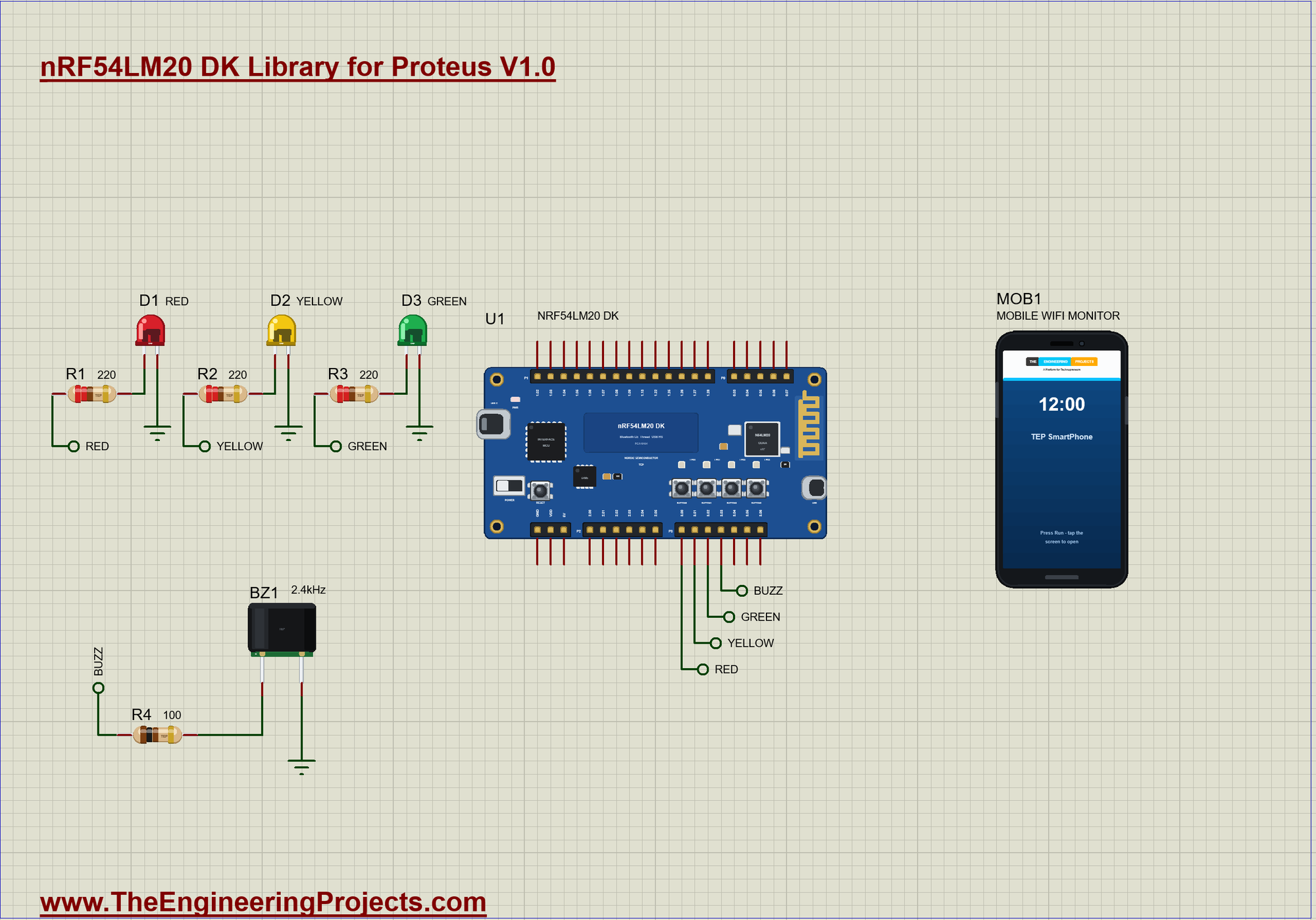
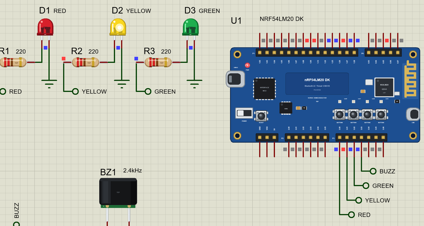
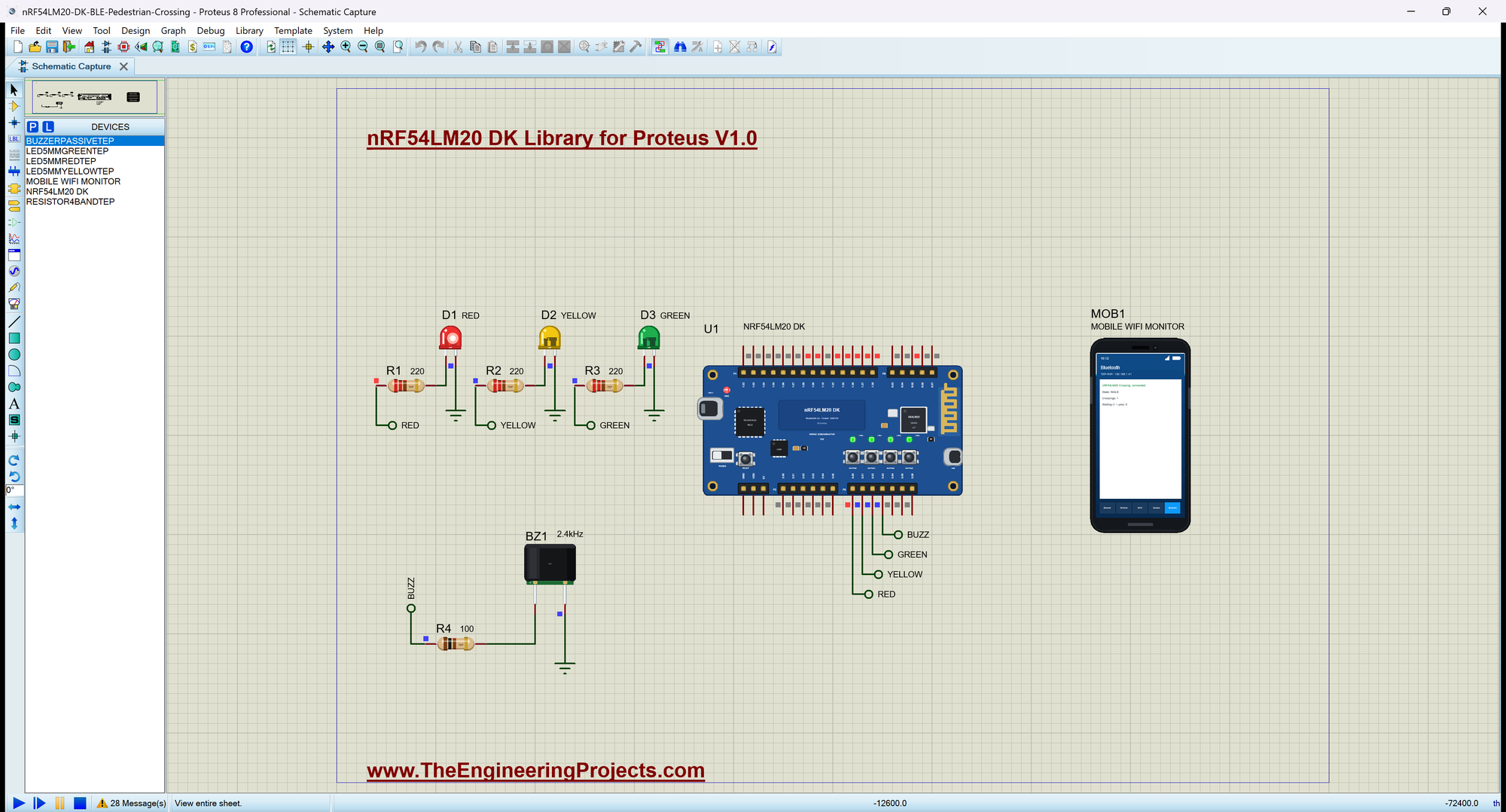
Open nRF54LM20-DK-BLE-Pedestrian-Crossing.pdsprj. U1 runs DK54LM_BLE_Crossing.hex; the cars' light is three of our 5mm LED Library for Proteus - D1 RED on P3.00, D2 YELLOW on P3.01, D3 GREEN on P3.02, each through a 220 ohm resistor; BZ1 is our Passive Buzzer Library for Proteus on P3.03; MOB1 is our Mobile WiFi Monitor, the phone.
| State | Cars | Pedestrians | How long |
|---|---|---|---|
| CARS GO | GREEN | wait (LED0 to LED3 off) | until a request, at least 4 s |
| YELLOW | YELLOW | wait | 2 s |
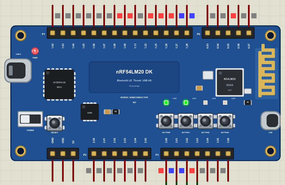
| WALK | RED | LED0 to LED3 count down, the buzzer ticks | 8 s |
| CLEARING | RED | off | 1 s |
| NIGHT | YELLOW flashing | requests wait | BUTTON1 on / off |
The States
The crossing is always in exactly one state, and each state has a name for the monitor and the phone:
enum State { CARS_GO, CARS_YELLOW, WALK, CLEARING, NIGHT };
const char *const STATE_NAMES[] = {"CARS GO", "YELLOW", "WALK", "CLEARING", "NIGHT"};
Entering a State
enter() sets the lights for the new state, remembers when it started and tells the phone. Entering WALK also counts the crossing and clears the request:
void enter(State s) {
  state = s;
  since = millis();
  nextTick = 0;
  if (s == CARS_GO) { lights(0, 0, 1); walkBar(0); }
  else if (s == CARS_YELLOW) lights(0, 1, 0);
  else if (s == WALK) { lights(1, 0, 0); walkBar(4); waiting = false; waitingChar.writeValue(0); crossings++; crossingsChar.writeValue(crossings); }
  else if (s == CLEARING) { lights(1, 0, 0); walkBar(0); }
  else { lights(0, 1, 0); walkBar(0); }
  stateChar.writeValue(STATE_NAMES[s]);
  Serial.print(F(">> ")); Serial.print(STATE_NAMES[s]);
  if (s == WALK) { Serial.print(F(" (crossing ")); Serial.print(crossings); Serial.print(')'); }
  Serial.println();
}
A Request
BUTTON0 calls request(). A second press, or a press while people are already walking, changes nothing:
void request() {
  if (waiting || state == WALK || state == CLEARING) return;
  waiting = true;
  waitingChar.writeValue(1);
  Serial.println(state == NIGHT ? F("Request (night mode: it waits)") : F("Request: the pedestrians are waiting"));
}
The Steps
run() is called from the loop over and over. It moves to the next state when the time is up, counts the walk time down on the four LEDs and ticks the buzzer - once a second, then four times a second in the last 2 s:
void run() {                                                // the crossing's steps
  const unsigned long t = millis() - since;
  if (state == CARS_GO && waiting && t >= MIN_GREEN) enter(CARS_YELLOW);
  else if (state == CARS_YELLOW && t >= YELLOW_MS) enter(WALK);
  else if (state == WALK) {
    if (t >= WALK_MS) { enter(CLEARING); return; }
    walkBar(4 - t * 4 / WALK_MS);                           // the countdown: 4 LEDs, one off every 2 s
    const unsigned long gap = t >= WALK_MS - 2000 ? 250 : 1000;   // the ticks: once a second, 4 a second at the end
    if (millis() >= nextTick) { nextTick = millis() + gap; tone(BUZZ, 2400, 40); }
  }
  else if (state == CLEARING && t >= CLEAR_MS) enter(CARS_GO);
  else if (state == NIGHT && millis() >= nextTick) { nextTick = millis() + 500; blink = !blink; lights(0, blink, 0); }
}
The Bluetooth Service
Three characteristics carry the state, the number of crossings and a waiting request, each with a readable 0x2901 name for the phone:
BLEService crossingService("19B100D0-E8F2-537E-4F6C-D104768A1214");
BLEStringCharacteristic stateChar("19B100D1-E8F2-537E-4F6C-D104768A1214", BLERead | BLENotify, 12);
BLEIntCharacteristic crossingsChar("19B100D2-E8F2-537E-4F6C-D104768A1214", BLERead | BLENotify);
BLEByteCharacteristic waitingChar("19B100D3-E8F2-537E-4F6C-D104768A1214", BLERead | BLENotify);
Run the Simulation
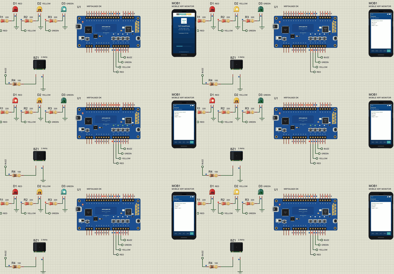
Press Run. The serial monitor - the same window as our TEP Serial Monitor Advance for Proteus - shows the name the kit advertises, and the cars get green:
nRF54LM20 DK Bluetooth Pedestrian Crossing - The Engineering Projects
Advertising as "nRF54LM20 Crossing"   BUTTON0 = request, BUTTON1 = night mode
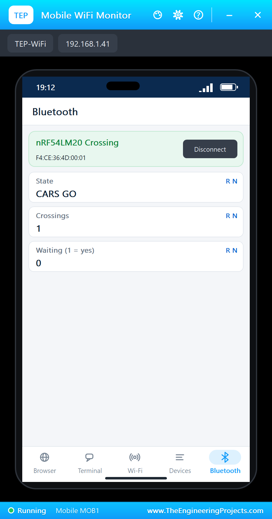
>> CARS GO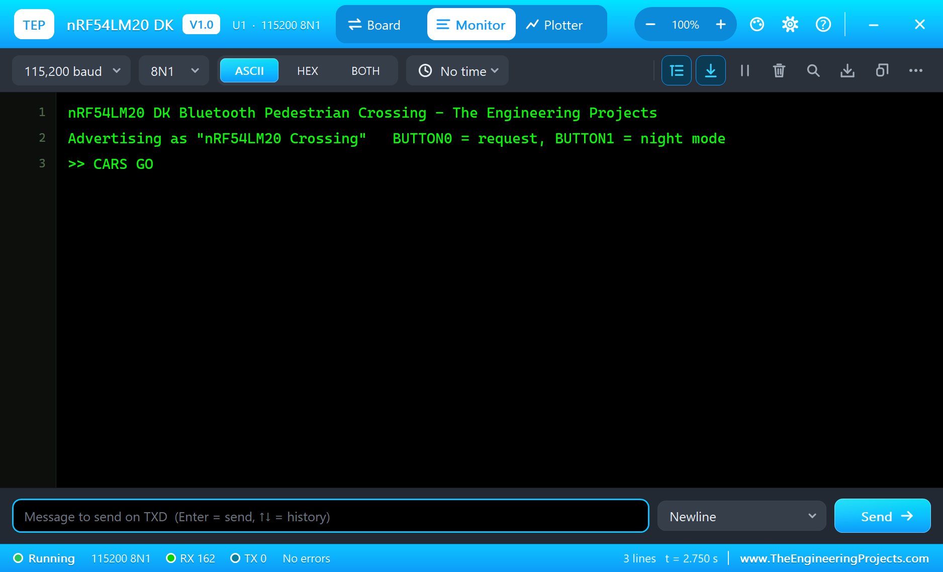
Connect the Phone
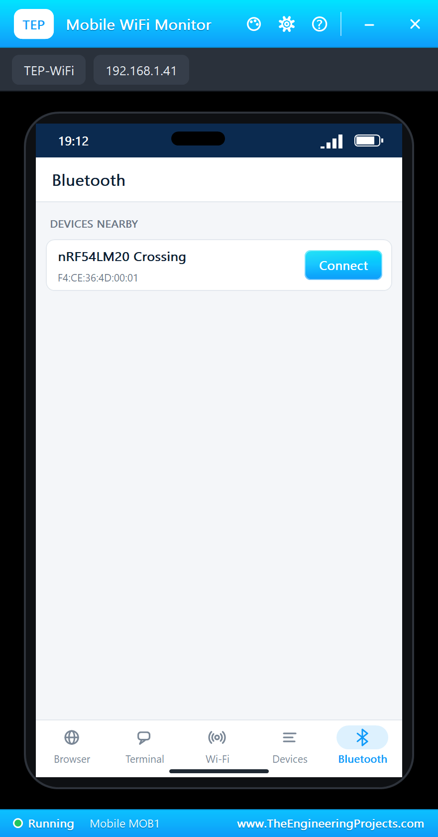
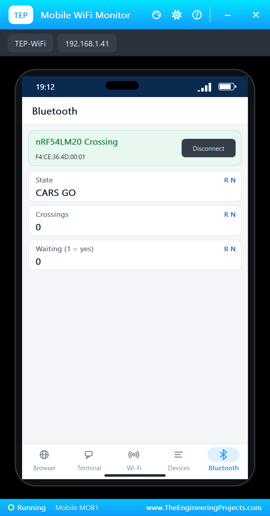
On the phone open the Bluetooth app, press SCAN and connect to "nRF54LM20 Crossing":
Press the Button
Click BUTTON0. The cars have had their 4 s of green, so the light turns yellow at once, and 2 s later red:
Walk
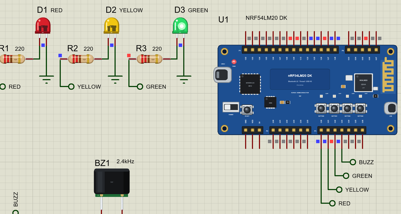
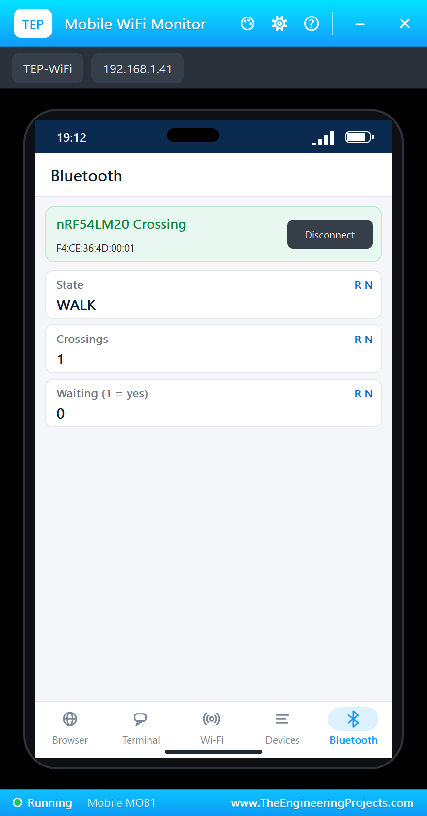
Red for the cars, and the pedestrians walk: all four of the kit's LEDs light and the buzzer ticks. Here is the complete circuit while the simulation runs:
The Countdown
Every 2 s one LED goes out; in the last 2 s the buzzer ticks faster. Then CLEARING for 1 s, and the cars get green again:
Night Mode
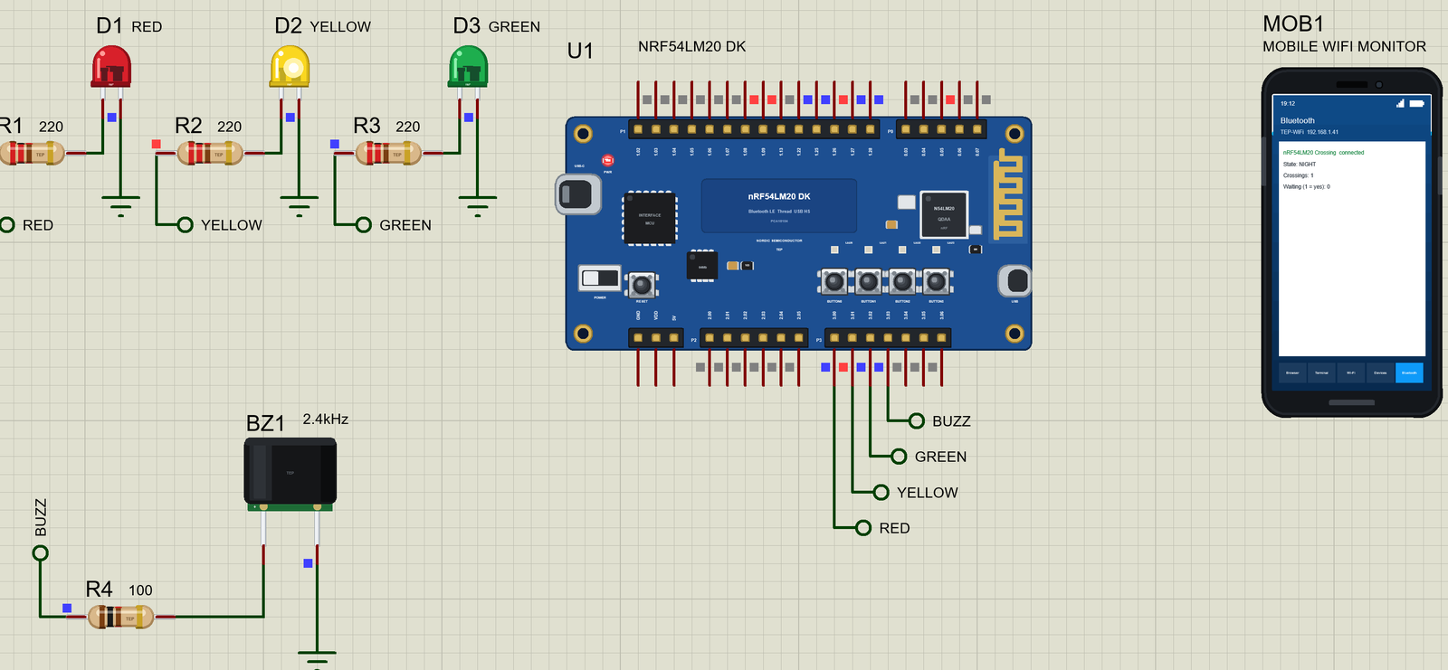
Click BUTTON1: NIGHT, the yellow LED flashes and a request waits. BUTTON1 again ends the night mode:
Phone connected
Request: the pedestrians are waiting
>> YELLOW
>> WALK (crossing 1)
>> CLEARING
>> CARS GO
>> NIGHT
Request (night mode: it waits)
Night mode off
>> CARS GO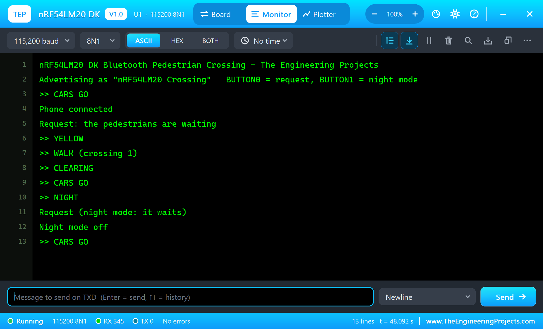
Why a State Machine?
A crossing written with delay() would be blind while it waits: no buttons, no Bluetooth, no ticking. As a state machine, every pass of the loop asks one question - is it time for the next state? - and the rest of the time the kit is free. The same pattern runs washing machines, lifts and vending machines.
The Sound for Blind Pedestrians
Many countries add an accessible signal to crossings: a slow tick while pedestrians wait or walk and a faster one when the time is nearly up, often with a vibrating arrow on the button. Our buzzer ticks once a second during WALK and four times a second in the last 2 s. tone() with a duration makes each tick without stopping the loop.
Why a Minimum Green?
Without a minimum green, a pedestrian pressing the button again and again could stop the traffic every few seconds. Real controllers give the main road a minimum green time - often 20 s or more; the demo uses 4 s so the simulation stays short.
How Long Should the Walk Phase Be?
Traffic engineers size the walk phase from the width of the road and a walking speed. A common design speed is about 1.2 m/s; slower values are used near schools, hospitals and homes for the elderly. A 10 m road at 1.2 m/s needs a little over 8 s, plus a few seconds for people to notice the signal and step off the kerb. That is why the demo gives WALK 8 s and then a short CLEARING phase in which nobody gets green: anybody still on the road has time to reach the other side before the cars move.
Reading the Buttons Safely
A real push button bounces: for a few milliseconds its contacts open and close many times, and a fast loop could read one press as several. The sketch reacts only to the change from HIGH to LOW, and a request that is already waiting ignores further presses, so a bouncing BUTTON0 does no harm. BUTTON1 toggles the night mode, so on a real board it needs a short debounce time - accept a new press only 30 to 50 ms after the last change. In the Proteus simulation the kit's buttons are clean.
What the Phone Sees
The phone is a Bluetooth LE central: it scans, finds the advertised name and connects. Each characteristic is a small value with a UUID; the phone reads it once and then gets a notification whenever the kit writes a new value. That is how the state, the number of crossings and the waiting flag change on the phone the moment they change on the kit, without the phone asking again and again.
Resistors for the LEDs
A 5 mm LED drops about 2 V; with a 3.3 V pin and 220 ohm the current is about 6 mA - bright enough on a desk and gentle on the pin. The buzzer gets 100 ohm. Our LED and resistor libraries show the current and the brightness in their pop-ups.
The nRF54L Series
Nordic's nRF54L chips are the successors of the nRF52 family: a faster Cortex-M33, a RISC-V coprocessor for real-time jobs, a newer radio and lower power. The nRF54LM20 is the version with the most memory and I/O and a high-speed USB port. Its multicore cousin with even more processing power is the nRF54H20 - see our nRF54H20 DK Library for Proteus.
Try It Yourself
- Make the walk time longer when the button is held down (for slower pedestrians).
- Blink the green LED for 2 s before the yellow.
- Count the requests that came during the night mode and send the count to the phone.
- Add a writable characteristic so the phone can press the button.
Ideas to Extend the Crossing
- Add a second crossing on the P2 header for a crossroads.
- Use a PIR sensor to start the walk phase for people who forget the button.
- Show a countdown in seconds on a 7-segment display.
- Log every crossing with a time stamp on the phone.
Your Own Sketches
Write the sketch in the Arduino IDE with the board Nordic nRF54LM20 DK (TEP Proteus), use Sketch > Export Compiled Binary and set the part's PROGRAM property to the .hex.
Moving to a Real nRF54LM20 DK
- Install Nordic's nRF Connect SDK with the board nrf54lm20dk/nrf54lm20a/cpuapp.
- Wire three LEDs with their resistors and a small buzzer (through a transistor) to free GPIOs on the headers.
- Start from Nordic's Bluetooth peripheral samples and Zephyr's GPIO and PWM APIs.
- Move the logic of the demo across: the states, the request, the countdown and the service.
- Program the kit through the interface MCU's USB and test with a phone app.
The pins, the states and the Bluetooth service stay the same; on the real kit Nordic's SDK takes the place of the Arduino calls.
Things to Know Before Using a Real nRF54LM20 DK
- Low-voltage GPIOs: check the voltage of the port you use before connecting a module.
- Active-HIGH LEDs: HIGH switches an LED on.
- Two USB ports: one for the interface MCU, one for the chip itself.
- Buzzers: drive a buzzer through a transistor; a pin alone gives only a few milliamps.
Properties of the nRF54LM20 DK
| Property | What it does |
|---|---|
| PROGRAM | the sketch: a .hex from TEP Boards for Proteus (board "Nordic nRF54LM20 DK") |
| MONITOR, BAUD, AUTOOPEN | the built-in serial monitor: on, its baud rate (115200), open at Run |
Troubleshooting
- The phone finds nothing: call
BLE.begin(), set a local name andBLE.advertise(); callBLE.poll()in loop(). - An LED stays dark: each 5 mm LED needs its resistor and its cathode (K) to ground; the pins are P3.00 to P3.02.
- A button does nothing: use
pinMode(BUTTONx, INPUT_PULLUP)and act whendigitalRead()is LOW. - A kit LED stays dark: the nRF54LM20 DK's LEDs light when the pin is HIGH.
- A number goes wrong above 32767: int is 16 bits in the simulation - use long.
Limitations of the Simulation
- Bluetooth LE: the kit is a peripheral only, with one phone as the central.
- 802.15.4 / Thread, the RISC-V coprocessor, the SoC's USB port and the external flash are drawn, not modelled.
- Your sketch gets 8 KB of RAM in the simulation, and int is 16 bits there.
- nRF54LM20 and Nordic Semiconductor are names of Nordic Semiconductor ASA and Arduino of Arduino, and the Bluetooth word mark belongs to Bluetooth SIG; this library is not made or endorsed by them or by Labcenter.
- Tested in Proteus 8.5 in November 2026 (the demo as shipped, about 48 s of simulation). Proteus 7 is not supported.
So, that was all about the nRF54LM20 DK Library for Proteus. I hope it helps you try your Bluetooth ideas in a simulation before the kit is on your desk - the LEDs, the buzzer, the buttons and the phone, all on one sheet. If you have any questions, ask in the comments and I will help you out. Till the next tutorial, take care and have fun!

Comments
0