


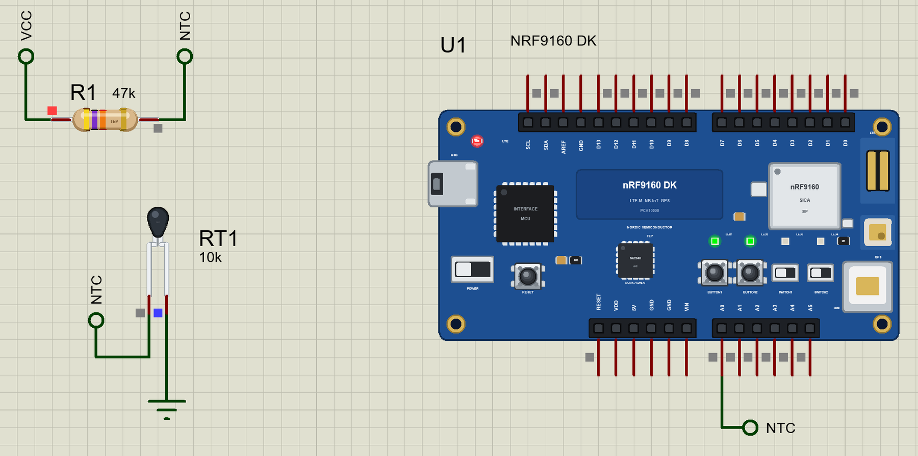
nRF9160 DK Library for Proteus: Cellular SMS Simulation


Hello friends, I hope you all are doing great. Today, I am going to share the nRF9160 DK Library for Proteus, so you can run a cellular IoT simulation of Nordic Semiconductor's nRF9160 development kit. The nRF9160 was Nordic's first cellular system-in-package: an Arm Cortex-M33, an LTE-M and NB-IoT modem and GPS under one metal shield. With this library the kit runs your Arduino sketch in Proteus 8.5, talks to its modem with AT commands and sends and receives SMS.
nRF9160 DK Library for Proteus
Latest version: V1.0 (November 2026, this tutorial)
Helping Tools
- Laptop WiFi Monitor: a laptop on the Wi-Fi of your design: a browser, a TCP / UDP terminal and ping
- Mobile WiFi Monitor: a smartphone that opens the pages of your board and sends it commands
- Serial Monitor Advance: a serial terminal window for the UART of your board
For the demo we built an SMS frost alarm for a greenhouse or an orchard far from any Wi-Fi. A small NTC thermistor measures the air; when it falls below the limit, the kit sends a FROST ALARM to the grower's phone, and the grower checks it and moves the limit by SMS.
NOTICE: Proteus has no nRF9160 model, so our team has put a lot of effort into building this board ourselves: the pins, the LEDs, the buttons and the cellular modem with SMS are all our own model, and your sketch compiles with our free TEP Boards for Proteus add-on. Your feedback is the fuel that keeps us going, so please tell us what you think in the comments below. And if our free libraries help you, you can buy us a coffee. So, let's get started with the nRF9160 DK Library for Proteus:
What is the nRF9160 DK?
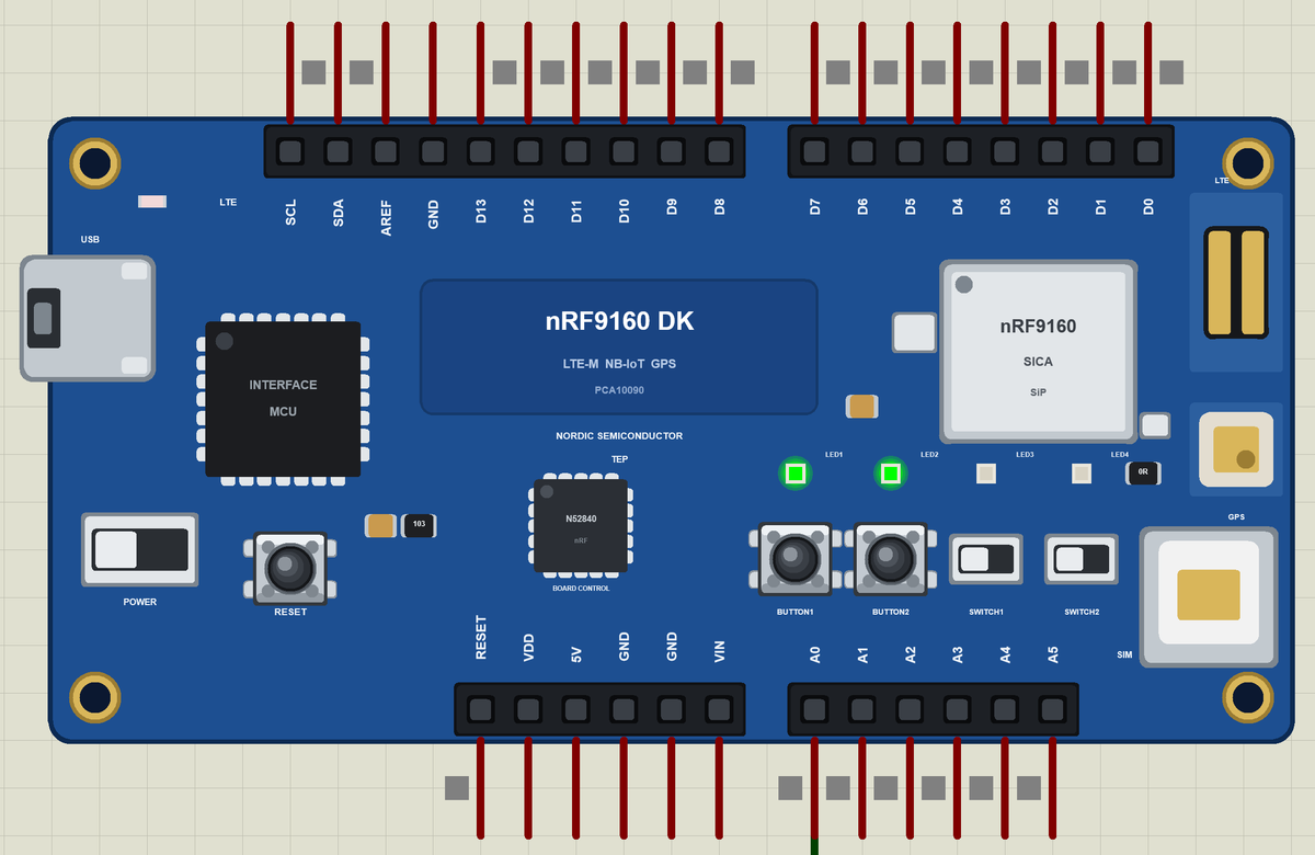
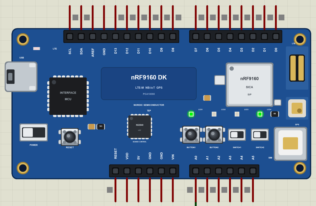
The nRF9160 DK (PCA10090) is Nordic Semiconductor's development kit for the nRF9160 SiP. The SiP joins the processor, the LTE-M / NB-IoT modem, the RF front end, GPS and the power management in one shielded package. The kit carries the SiP, a nano-SIM holder, an LTE antenna, a GPS antenna, an nRF52840 as the board controller, an interface MCU that programs it over USB, four LEDs, two buttons, two slide switches and Arduino Uno compatible headers.
| Part | The real nRF9160 DK | In the library |
|---|---|---|
| SiP | nRF9160: Cortex-M33, LTE-M / NB-IoT modem, GPS | your Arduino sketch, the modem on SerialModem |
| Cellular | LTE-M and NB-IoT with a nano-SIM | registration and SMS (text mode) |
| Board controller | an nRF52840 that routes the pins and the switches | drawn |
| LEDs | LED1 to LED4 on P0.02 to P0.05, active HIGH | LED1 to LED4 |
| Buttons | BUTTON1, BUTTON2 on P0.06, P0.07; SWITCH1, SWITCH2 | BUTTON1, BUTTON2; the switches drawn |
| Headers | Arduino Uno layout | D0 to D13, A0 to A5, SDA, SCL |
Cellular IoT in a Few Words
LTE-M and NB-IoT are the low-power branches of 4G. LTE-M carries more data and moves between cells, which suits trackers; NB-IoT sends small messages from deep inside buildings, which suits meters and sensors in a field. Both run on ordinary mobile networks, so a device works wherever there is coverage - no Wi-Fi, no gateway. SMS is still the simplest way to reach a person's phone.
Talking to the Modem
The sketch talks to the modem with AT commands on SerialModem: AT+CEREG? asks whether the modem is registered on the network, AT+CMGF=1 chooses text-mode SMS and AT+CMGS sends one. The modem answers with lines such as +CEREG: 0,1 - registered at home. On the real chip Nordic's modem library passes the same kind of commands to the modem.
The nRF91 Family
The nRF9160 started the family; the nRF9161 added DECT NR+ and the nRF9151 is the smaller, newer version. For the newest member see our nRF9151 DK Library for Proteus. The nRF9160 is still found in many trackers, meters and alarm systems in the field.
A simulation lets you try the whole flow before the kit and a SIM are on the desk: the sensor, the modem's answers and the SMS. When the sketch works in the Proteus simulation, the real kit only has to confirm it.
Features of the nRF9160 DK Library for Proteus
- The board as it looks: the blue kit with the nRF9160 SiP under its shield, the nano-SIM holder, the LTE and GPS antennas, the nRF52840 board controller, the interface MCU with its USB port, the power switch, RESET, the buttons, the slide switches, the four LEDs and the Arduino headers, drawn compact, with our small TEP signature.
- Your sketch: a .hex for "Nordic nRF9160 DK (TEP Proteus)" with D0 to D13, A0 to A5, LED1 to LED4, BUTTON1 and BUTTON2.
- The modem: AT commands on SerialModem - registration and SMS in text mode.
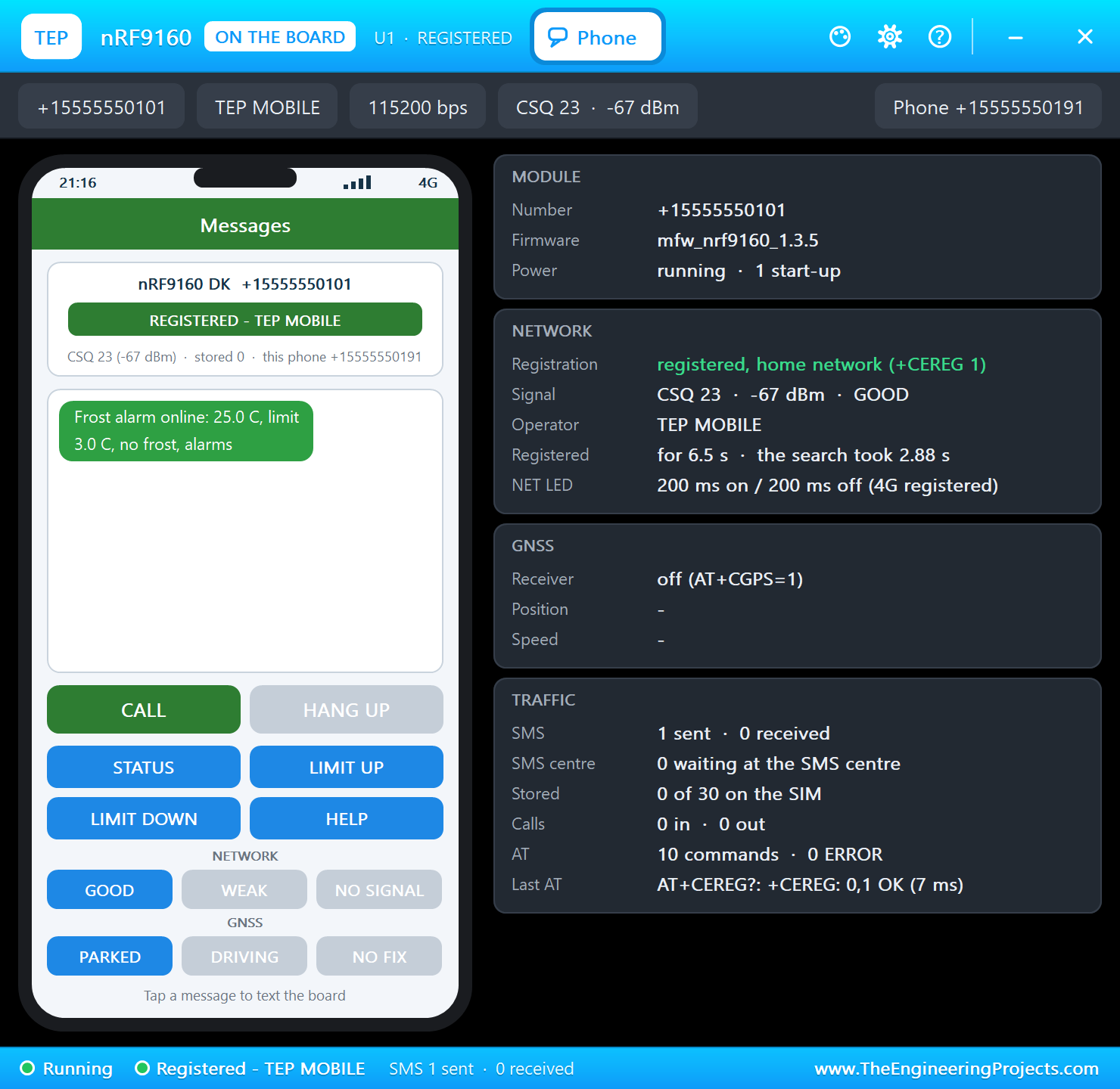
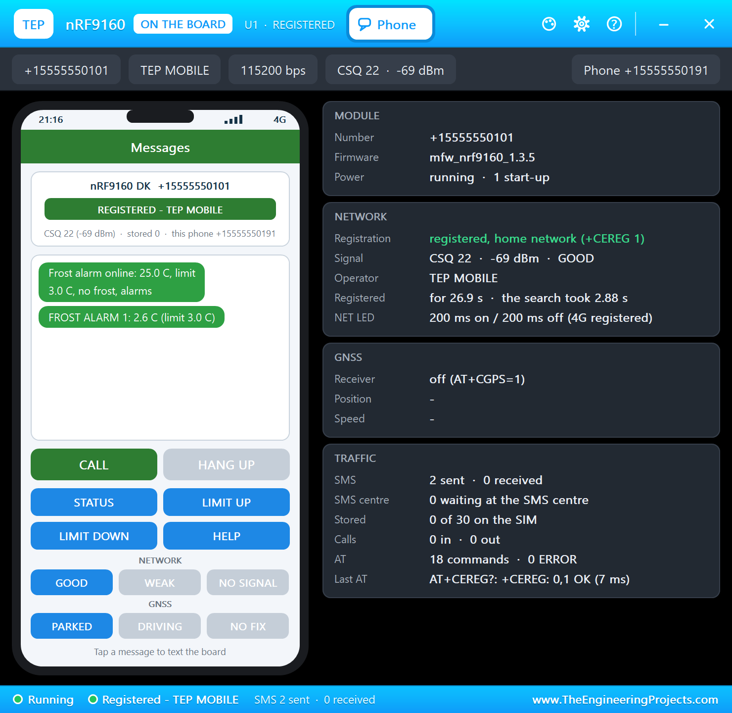
- The Phone window: the owner's phone receives and sends SMS, with four quick keys.
- A complete package: about 4.0 MB with the part, the add-on, the NTC thermistor, the resistor and the demo, without the source code of the models.
The nRF9160 DK in Proteus Simulation
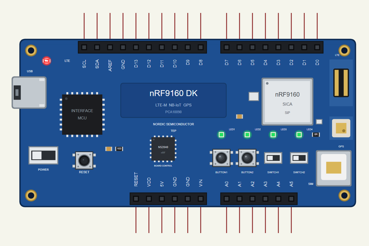
Search NRF9160 in Pick Devices; the device NRF9160 DK is in TEPNRF9160DK.LIB (Microprocessor ICs, Cellular Boards), with the prefix U. The USB port opens the serial monitor, a click on the SiP the Phone window.
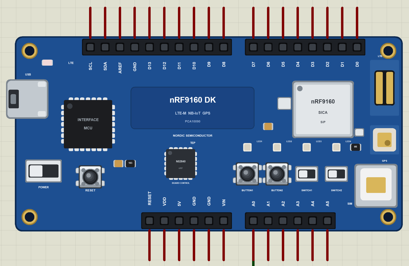
The Pins
| Pins | What the library does with them |
|---|---|
| D0 to D13 | GPIO, PWM, interrupt; D10 to D13 SPI |
| A0 to A5 | analogRead 0 to 1023 for 0 to 3.3 V, or GPIO |
| SDA, SCL | Wire |
| LED1 to LED4 | the green LEDs, lit when HIGH (the real P0.02 to P0.05) |
| BUTTON1, BUTTON2 | the buttons, LOW when pressed (the real P0.06, P0.07) |
| SerialModem, MODEM_ON | the modem's AT interface; HIGH starts the modem |
Download nRF9160 DK Library for Proteus
Click the button below to download nRF9160-DK-Library-for-Proteus-v1.0.zip (about 4.0 MB, without the source code of the models):
nRF9160 DK Library for Proteus V1.0- README.txt: installation, the demo, the pins, the properties, troubleshooting and the limits.
- Proteus Library Files:
TEPNRF9160DK.LIB, the NTC thermistor and the resistor (TEPNTC.LIB,TEPRESISTOR.LIB) and the phone and laptop libraries for your own designs. - Proteus Model Files:
TEPNET.DLL,TEPNTC.DLLandTEPRESISTOR.DLL. - Arduino Code: the demo sketch and the TEP Boards for Proteus add-on 1.87.0.
- Proteus Simulation: the demo project, its HEX file and copies of the DLLs.
No Proteus yet? Read How to Download and Install Proteus 7 and 8. New to libraries? Follow How to Install a New Library in Proteus.
How to Install nRF9160 DK Library for Proteus
- Close Proteus and extract the whole zip file, for example to your Desktop.
- Copy the files from Proteus Library Files into the LIBRARY folder of Proteus.
- Copy the DLLs from Proteus Model Files into the MODELS folder, replacing an older
TEPNET.DLL. - Delete
TEPNRF9160DK.IDXfrom the LIBRARY folder if it is there. - For your own sketches, copy Arduino Code\TEP Boards for Proteus\hardware into your Arduino sketchbook (Documents\Arduino) and restart the Arduino IDE; the board is Nordic nRF9160 DK (TEP Proteus).
- Start Proteus, press P and search for NRF9160.
Demo: an SMS Frost Alarm in Simulation
On a clear spring night the air near the ground can fall below zero while the day was warm. A few hours of frost kill blossoms and seedlings, so growers want a warning in time to start heaters, sprinklers or fans. A greenhouse or an orchard rarely has Wi-Fi, which makes a cellular alarm the natural choice.
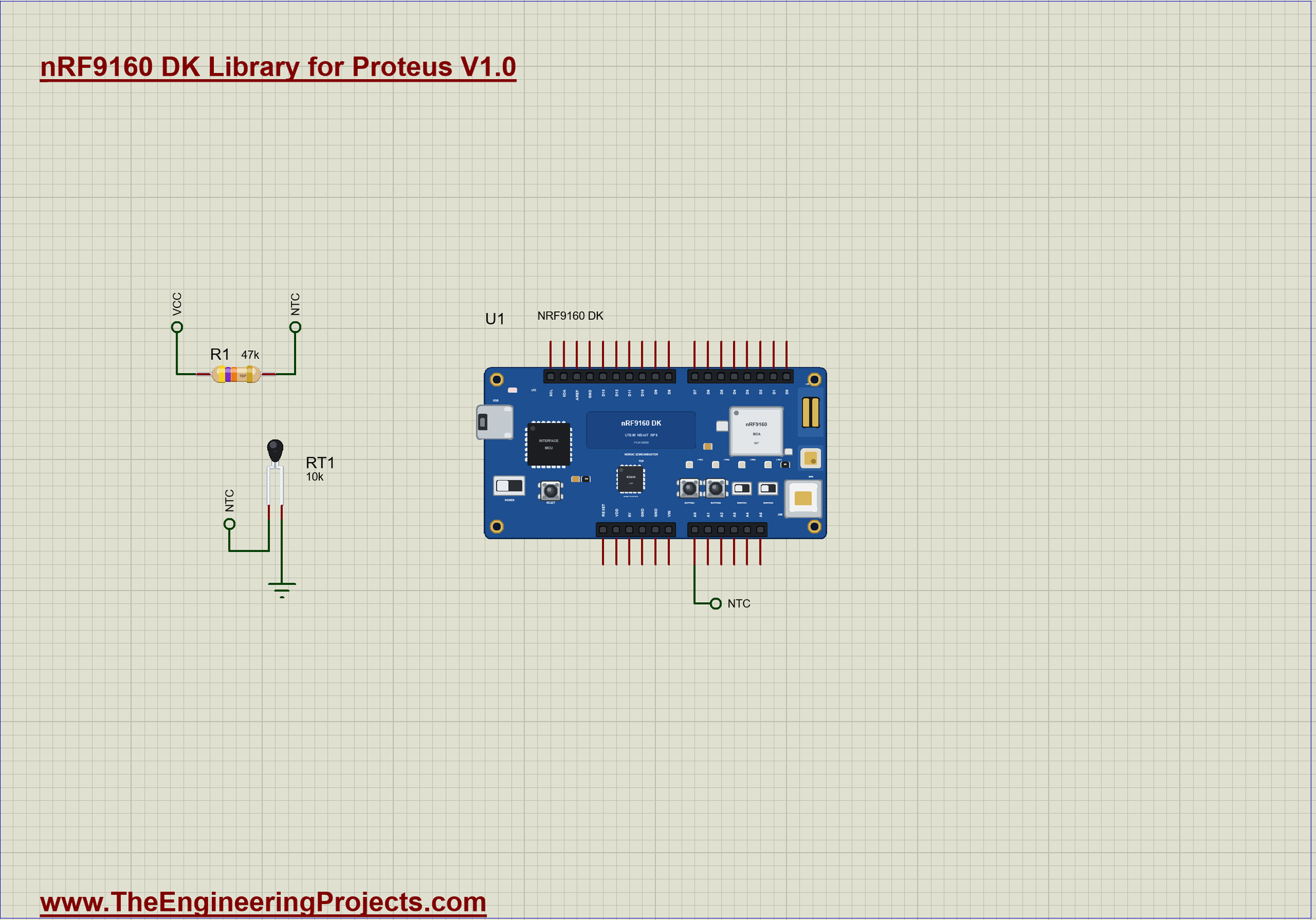
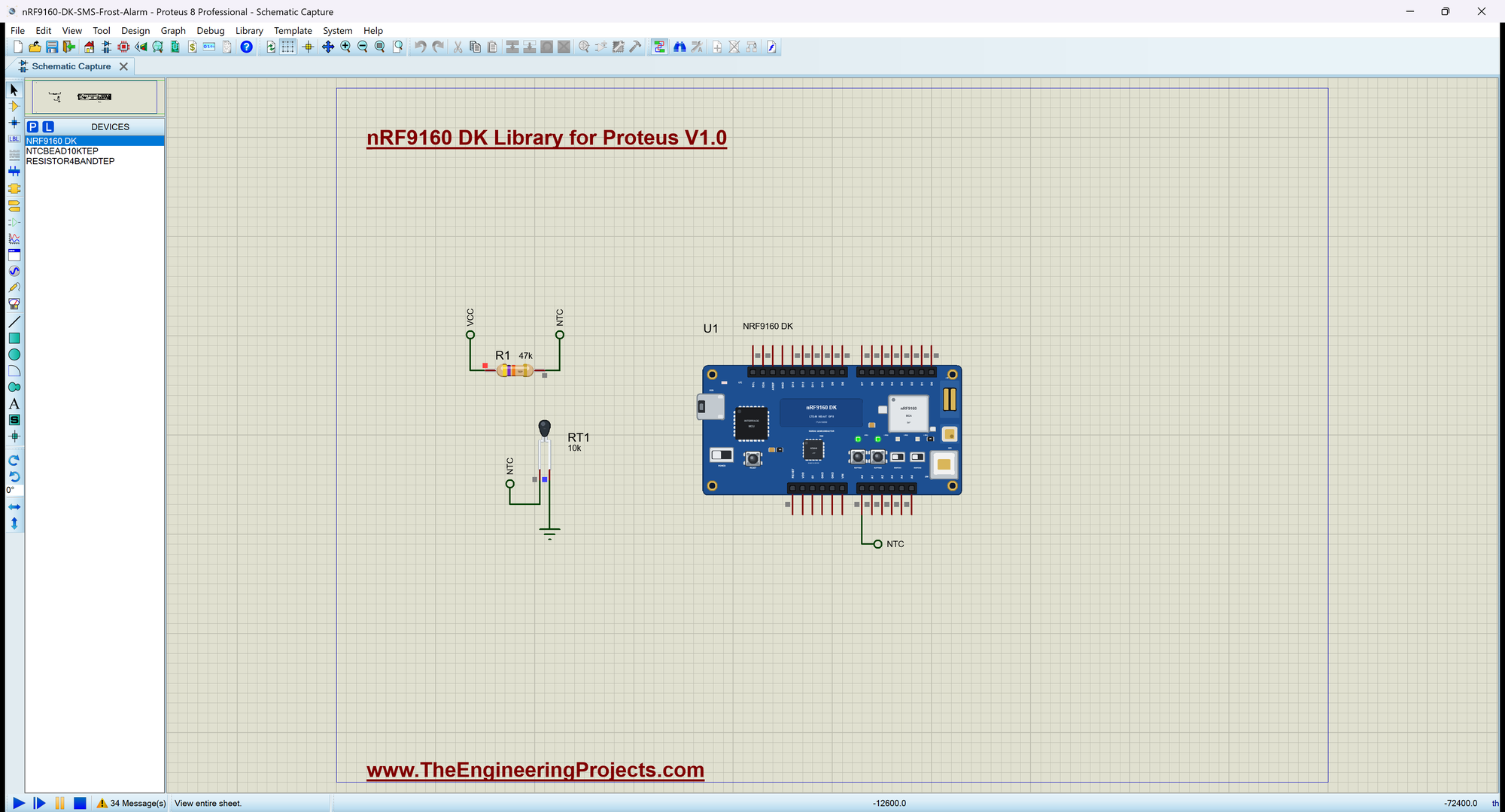
Open nRF9160-DK-SMS-Frost-Alarm.pdsprj. U1 runs DK9160_SMS_Frost_Alarm.hex; RT1 is the 10k NTC from our NTC Thermistor Library for Proteus, R1 the 47k resistor from our Resistor Library for Proteus - a divider from VCC through R1 to A0 and through RT1 to ground. The owner's phone is the kit's own Phone window.
| LED / key | What it means |
|---|---|
| LED1 | registered on the network |
| LED2 | FROST |
| LED3 | an SMS is going out |
| LED4 | above the limit, no frost |
| STATUS, LIMIT UP, LIMIT DOWN, HELP | the Phone window's quick keys = the SMS commands |
| BUTTON1, BUTTON2 | the status, a test alarm by SMS |
From the Divider to a Temperature
readTemp() turns the reading on A0 into the NTC's resistance and then into degrees with the B equation (B 3950, 10k at 25 C). A reading of 0 or 1023 means a broken wire, so the last value is kept:
float readTemp() {                                          // the NTC's resistance from the divider, then the B equation
  const int raw = analogRead(NTC_PIN);
  if (raw <= 0 || raw >= 1023) return tempC;                // (a broken wire: keep the last value)
  const float v = raw * ADC_V / 1023.0;                    // the voltage on A0 (47k keeps it below 3.3 V down to about -15 C)
  if (v >= SUPPLY_V) return tempC;
  const float ohms = R_FIXED * v / (SUPPLY_V - v);
  return 1.0 / (1.0 / T25 + log(ohms / R25) / BETA) - 273.15;
}
Frost and Frost Over
checkFrost() runs once a second. Below the limit it lights LED2 and sends the FROST ALARM; the frost is only over 1 C above the limit, so a temperature that wobbles around the limit does not send a message every second:
void checkFrost() {
  tempC = readTemp();
  if (!frost && tempC < limitC) {
    frost = true; alarms++;
    led(1, true); led(3, false);
    Serial.print(F(">> FROST: ")); Serial.print(tempC, 1); Serial.println(F(" C"));
    sendSms(owner, "FROST ALARM " + String(alarms) + ": " + String(tempC, 1) + " C (limit " + String(limitC, 1) + " C)");
  } else if (frost && tempC > limitC + HYST) {
    frost = false;
    led(1, false); led(3, true);
    Serial.print(F(">> Frost over: ")); Serial.print(tempC, 1); Serial.println(F(" C"));
    sendSms(owner, "Frost over: " + String(tempC, 1) + " C");
  }
}
Sending an SMS
sendSms() uses the modem's text mode: AT+CMGS with the number, the modem's > prompt, the text and Ctrl+Z to send it. LED3 flashes while it goes out:
void sendSms(const String &to, const String &text) {
  if (!registered) { Serial.println(F("(no network: the SMS waits)")); return; }
  led(2, true); flashUntil = millis() + FLASH_MS;           // LED3: an SMS is going out
  SerialModem.print(F("AT+CMGS=\""));
  SerialModem.print(to);
  SerialModem.println(F("\""));
  unsigned long end = millis() + 2000;
  while (millis() < end && SerialModem.read() != '>') { }   // the modem's prompt
  SerialModem.print(text);
  SerialModem.write(26);                                    // Ctrl+Z ends the text
  Serial.print(F("SMS to ")); Serial.print(to); Serial.print(F(": ")); Serial.println(text);
  sentSms++;
  delay(200);
}
Commands from the Phone
A new SMS arrives as a +CMT line with the sender, followed by the text. command() acts on the text and answers the sender:
void command(const String &from, String text) {
  text.trim(); text.toUpperCase();
  Serial.print(F("SMS from ")); Serial.print(from); Serial.print(F(": ")); Serial.println(text);
  if (text == "STATUS") sendSms(from, status());
  else if (text == "LIMIT UP" || text == "LIMIT DOWN") {
    limitC += text == "LIMIT UP" ? 0.5 : -0.5;
    Serial.print(F(">> The limit is now ")); Serial.print(limitC, 1); Serial.println(F(" C"));
    sendSms(from, "Limit " + String(limitC, 1) + " C, now " + String(tempC, 1) + " C");
  }
  else sendSms(from, "Commands: STATUS, LIMIT UP, LIMIT DOWN, HELP");
}
Starting the Modem
startModem() switches the modem on, waits for its OK, turns the echo off, chooses text-mode SMS and asks for new messages straight away:
void startModem() {
  pinMode(MODEM_ON, OUTPUT);
  digitalWrite(MODEM_ON, HIGH);                             // the modem starts (on the real chip: nrf_modem_lib_init())
  SerialModem.begin(115200);
  Serial.println(F("Starting the nRF9160 modem"));
  while (!sendAT("AT", 1000)) { }                           // it answers once it has started
  sendAT("ATE0", 500);
  sendAT("AT+CMGF=1", 500);                                 // SMS as text
  sendAT("AT+CNMI=2,2,0,0,0", 500);                         // a new SMS comes straight to the AT interface
  Serial.println(F("Modem ready: SMS on, waiting for the network"));
}
Run the Simulation
Press Run. The serial monitor - the same window as our TEP Serial Monitor Advance for Proteus - shows the modem starting; the LTE LED blinks while it searches, and LED1 lights once it is registered:
nRF9160 DK Cellular SMS Frost Alarm - The Engineering Projects
Starting the nRF9160 modem
Modem ready: SMS on, waiting for the network
SMS: STATUS, LIMIT UP, LIMIT DOWN, HELP   BUTTON1 = the status, BUTTON2 = a test alarm
Status: LTE searching, 25.0 C, limit 3.0 C, no frost, alarms 0, SMS sent 0
LTE: registered on the network
SMS to +15555550191: Frost alarm online: 25.0 C, limit 3.0 C, no frost, alarms 0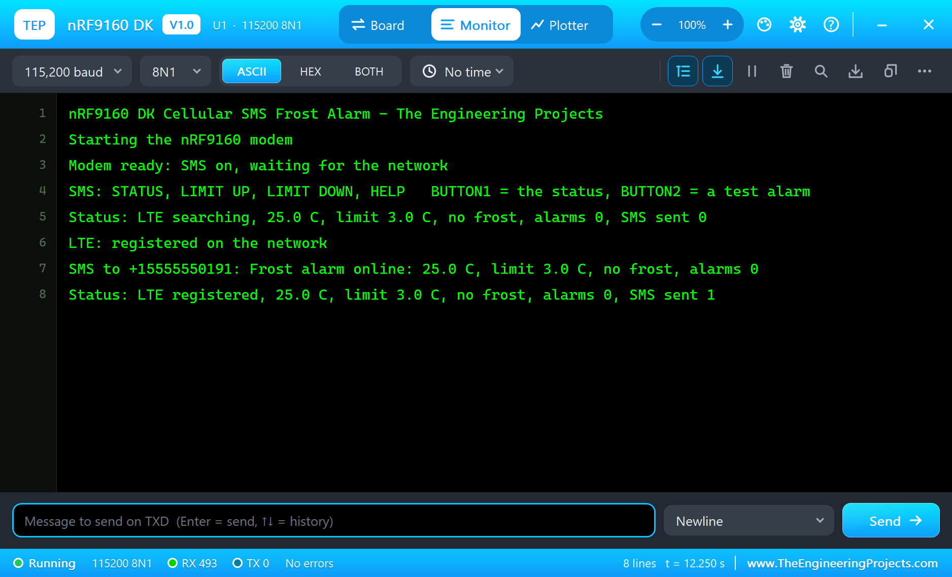
A Frosty Night
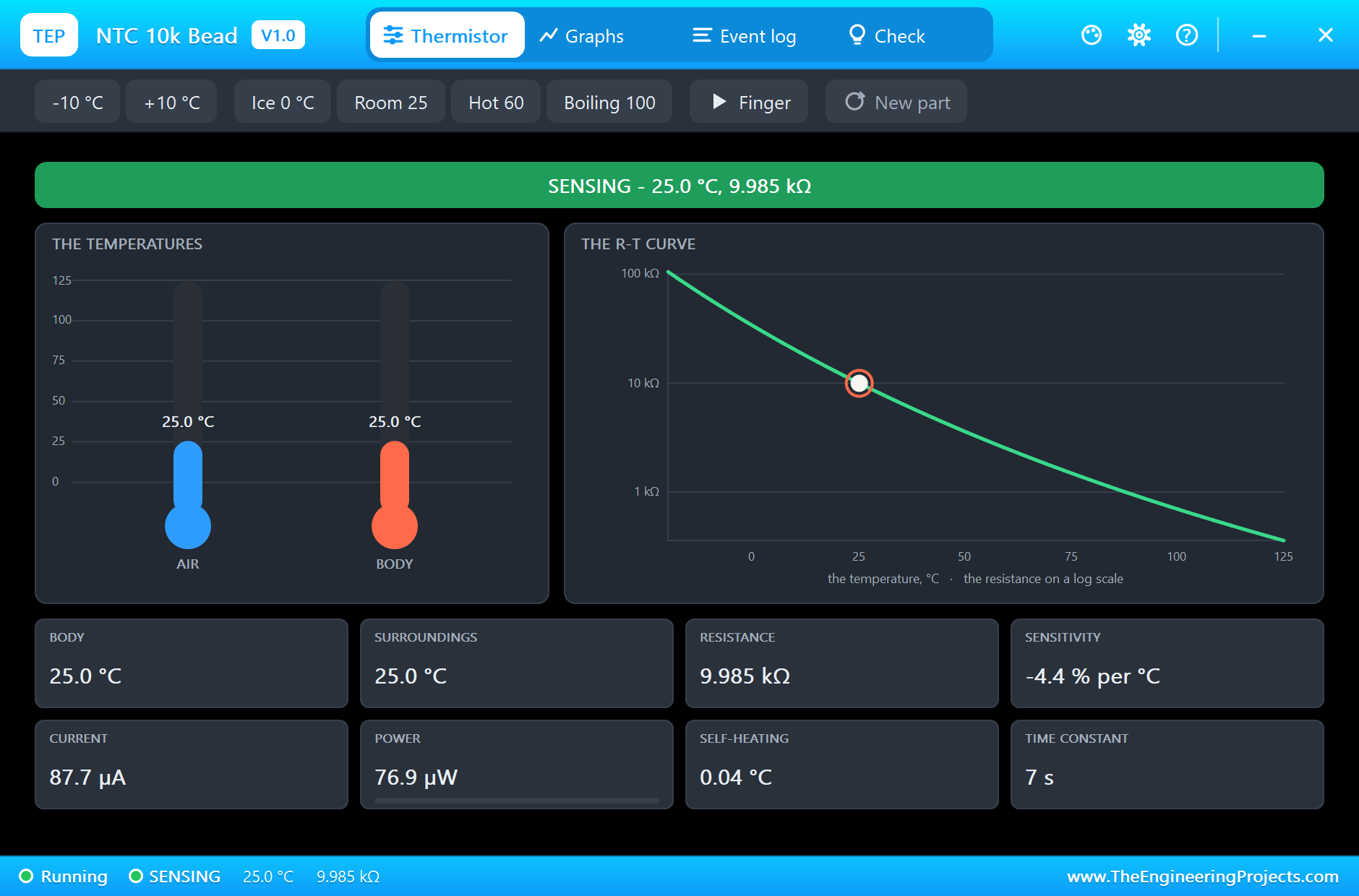
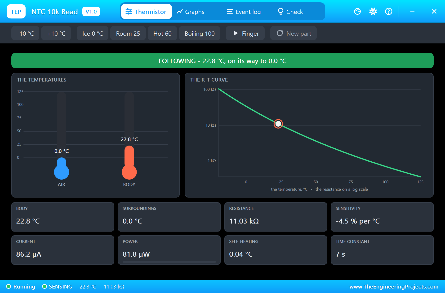
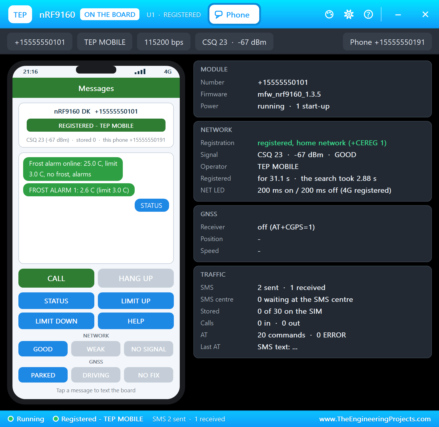
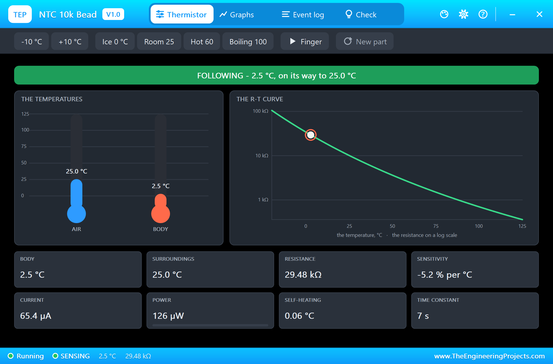
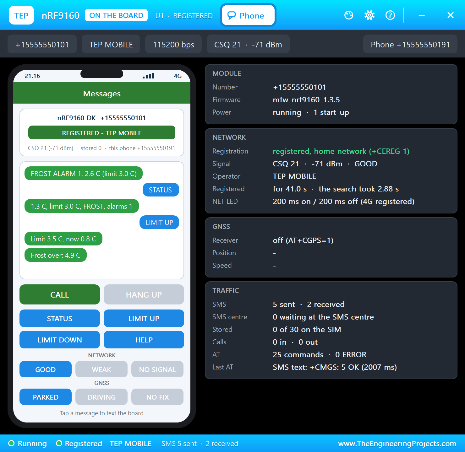
In the NTC's window click Ice: the bead cools down in a few seconds. Below 3.0 C LED2 lights and the FROST ALARM goes out:
Here is the complete circuit while the simulation runs:
Status and the Limit
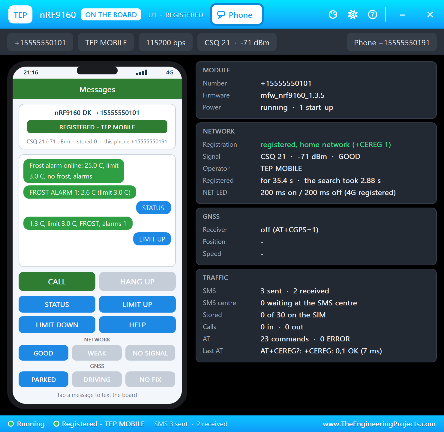
Press STATUS in the Phone window for a report, and LIMIT UP to raise the limit by 0.5 C:
Morning
Click Room in the NTC's window: the bead warms up, and 1 C above the limit the alarm ends with "Frost over"; LED4 lights again. On the kit, BUTTON1 sends the status and BUTTON2 a test alarm:
>> FROST: 2.6 C
SMS to +15555550191: FROST ALARM 1: 2.6 C (limit 3.0 C)
SMS from +15555550191: STATUS
SMS to +15555550191: 1.3 C, limit 3.0 C, FROST, alarms 1
Status: LTE registered, 0.9 C, limit 3.0 C, FROST, alarms 1, SMS sent 3
SMS from +15555550191: LIMIT UP
>> The limit is now 3.5 C
SMS to +15555550191: Limit 3.5 C, now 0.8 C
>> Frost over: 4.9 C
SMS to +15555550191: Frost over: 4.9 C
>> BUTTON1: status
SMS to +15555550191: 10.0 C, limit 3.5 C, no frost, alarms 1
>> BUTTON2: a test alarm
SMS to +15555550191: TEST ALARM: 12.2 C, limit 3.5 C, no frost, alarms 1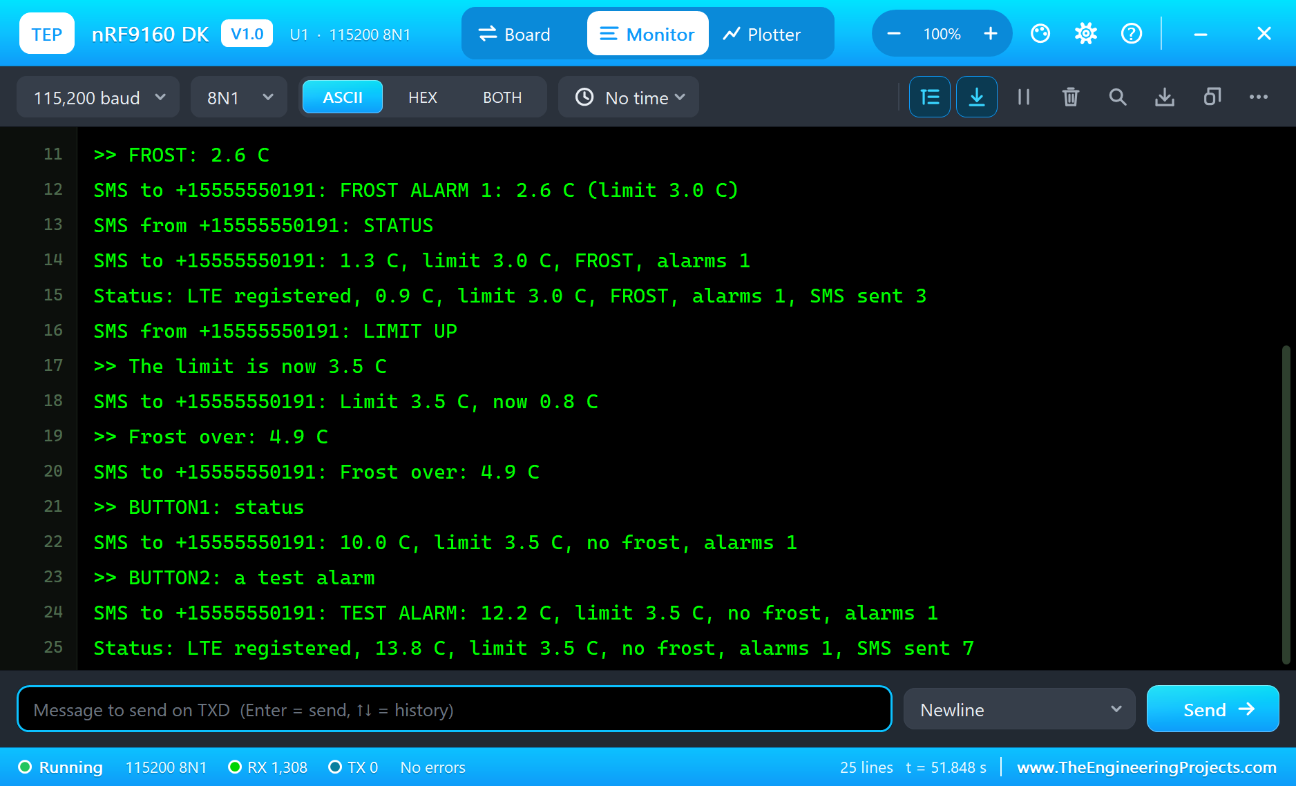
How an NTC Thermistor Measures
An NTC (negative temperature coefficient) thermistor is a resistor whose value falls as it warms up: our 10k bead has 10 kilo-ohm at 25 C, about 33 kilo-ohm at 0 C and less than 4 kilo-ohm at 50 C. In a divider that change becomes a voltage the ADC can read. The B equation turns the resistance back into a temperature to within a fraction of a degree over a wide range.
Why 47k and Not 10k?
The divider runs from the 5 V rail, but the analog inputs read 0 to 3.3 V. With 47k on top, the voltage on A0 stays below 3.3 V down to about -15 C, and the reading is most sensitive around zero - exactly where a frost alarm needs it. A 10k resistor would be better at room temperature but would push A0 over its range in the cold.
Hysteresis
A temperature right at the limit wobbles by a few hundredths of a degree. Without hysteresis the alarm would switch on and off and send a stream of messages. The sketch sets FROST below the limit and clears it only 1 C above it - the same idea a thermostat uses.
Where to Put the Sensor
Frost forms first near the ground on still, clear nights. Growers mount the sensor at the height of the blossoms or seedlings, in a small radiation shield so the sky or the sun does not fool it. A long two-wire cable to the thermistor is fine; keep the kit and its antennas where the signal is good.
What Growers Do with the Warning
A frost warning is only useful if there is time to act. Greenhouses switch on heaters or close thermal screens. Orchards start wind machines that mix the warmer air a few metres up with the cold layer near the ground, or run sprinklers: as the water freezes on the blossoms it releases heat and holds them at about 0 C. All of these need minutes to an hour to work, which is why the limit is set a few degrees above freezing and why it can be moved by SMS as the night goes on.
Why SMS and Not the Internet?
A cellular modem can also send data to a cloud service over IP, and many products do. SMS has advantages for an alarm: it reaches any phone without an app, it works on the simplest plans, and the phone shows it even when it is locked. The cost is a few cents a message, so the sketch sends only when something changes - the alarm, the end of the frost, an answer to a command - and never every second. A status line every 10 s goes to the serial monitor instead, for the person at the desk.
Reading the Status Line
Every 10 s the monitor prints the network state, the temperature, the limit, whether there is frost, the number of alarms and the number of SMS sent. While the bead cools, the line shows the temperature falling step by step: 25.0 C, 14.3 C, 3.5 C - and then the FROST line a moment later. It is the easiest way to see what the sketch sees without a phone.
Try It Yourself
- Send a second alarm when the temperature falls another 2 C.
- Send the minimum temperature of the night every morning.
- Switch a heater or a fan with a relay on D7 while it is frosty.
- Store the limit in EEPROM so it survives a reset.
Ideas to Extend the Alarm
- Add a second thermistor on A1 for a second greenhouse.
- Allow only the owner's number to change the limit.
- Add a soil moisture sensor and a daily report.
- Add the GPS position for an alarm that moves with a trailer.
Your Own Sketches
Write the sketch in the Arduino IDE with the board Nordic nRF9160 DK (TEP Proteus), use Sketch > Export Compiled Binary and set the part's PROGRAM property to the .hex.
Moving to a Real nRF9160 DK
- Install Nordic's nRF Connect SDK with the board nrf9160dk/nrf9160/ns.
- Put a nano-SIM with an LTE-M or NB-IoT plan into the holder and fit the antennas.
- Start from Nordic's SMS sample; the modem library sends the same kind of AT commands.
- Wire the divider: 47k from VDD to A0, the NTC from A0 to GND (on the real kit the I/O runs at 1.8 or 3.3 V).
- Move the logic of the demo across: the B equation, the hysteresis and the commands.
The pins, the commands and the messages stay the same; on the real kit Nordic's SDK takes the place of the Arduino calls.
Things to Know Before Using a Real nRF9160 DK
- A SIM and a plan: LTE-M or NB-IoT must be offered where the kit is used; SMS must be part of the plan.
- Antennas: keep the LTE antenna clear of metal.
- Shared pins: on the real kit the LEDs, buttons and switches share D2 to D9 through the board controller.
- 1.8 V or 3.3 V: the kit's I/O voltage is selectable; supply the divider from the same voltage the ADC uses.
Properties of the nRF9160 DK
| Property | What it does |
|---|---|
| PROGRAM | the sketch: a .hex from TEP Boards for Proteus (board "Nordic nRF9160 DK") |
| MONITOR, BAUD, AUTOOPEN | the built-in serial monitor: on, its baud rate (115200), open at Run |
Troubleshooting
- The modem never answers: set
MODEM_ONHIGH and callSerialModem.begin(115200)first; send AT until it answers OK. - No SMS arrives:
AT+CMGF=1andAT+CNMI=2,2,0,0,0bring a new SMS straight to SerialModem. - The temperature looks wrong: the NTC is the lower half of the divider - 47k from VCC to A0, the NTC from A0 to GND.
- No alarm: the frost needs the temperature below the limit; check the limit with STATUS.
- A number goes wrong above 32767: int is 16 bits in the simulation - use long.
Limitations of the Simulation
- Cellular: registration and SMS in text mode are modelled; data connections, voice, PSM and eDRX are not.
- The nRF52840 board controller, SWITCH1 and SWITCH2 are drawn, not modelled.
- Your sketch gets 8 KB of RAM in the simulation, and int is 16 bits there.
- nRF9160, nRF52840 and Nordic Semiconductor are names of Nordic Semiconductor ASA and Arduino of Arduino; this library is not made or endorsed by them or by Labcenter.
- Tested in Proteus 8.5 in November 2026 (the demo as shipped, about 52 s of simulation). Proteus 7 is not supported.
So, that was all about the nRF9160 DK Library for Proteus. I hope it helps you try your cellular IoT ideas in a simulation before the kit and a SIM are on your desk - the sensor, the modem and the SMS, all on one sheet. If you have any questions, ask in the comments and I will help you out. Till the next tutorial, take care and have fun!

Comments
0